1
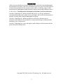
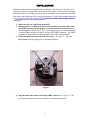
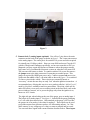
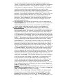
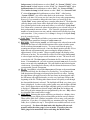
FOR CAN VEHICLES by USER MANUAL FIRMWARE VERSION 3.4 www.aeroforcetech.com Made in the USA! Patent Pending WARNING Vehicle operator should focus primary attention to the road while using the Interceptor. The information provided by this device should be observed as part of a normal sequence of observations performed in the operation of the vehicle, as with any gauge or other instrumentation. Interceptor settings should be changed only during conditions when it is safe to do so. Focusing on the road should be the primary concern of the driver. Aeroforce Technology Inc. shall not be held liable in any way for any incidental or consequential damages to the vehicle, driver, passengers, and or other involved parties or property occurring while using the Interceptor scan gauge. Aeroforce Technology Inc. shall not be liable for technical or editorial errors or omissions made herein, nor for incidental or consequential damages resulting from the furnishing or use of this manual. Aeroforce Technology Inc. reserves the right to make changes to this document and the product described without notice. Copyright 2005-2008 Aeroforce Technology, Inc. All rights reserved. 2 INSTALLATION Read these instructions thoroughly before installation. Also, be sure to check for your vehicle specific notes in appendix A at the end of this manual. There could be important information there concerning your gauge and its installation. New parameters are added from time to time, and may not be listed in this manual. For the latest updated manual go to www.aeroforcetech.com/usermanual.html and select the latest release that pertains to your gauge. 1. Make sure the car’s ignition is turned off. 2. Run included 5’, or optional 9’ main cable, and three wire mini cable, from the OBD2 connector (do not plug in yet) to the location of the Interceptor(s). The Interceptor will fit in any 2 1/16” or 52mm gauge pod, or can be mounted in a custom fashion anywhere within 5 (9) feet of the OBD2 connector. The OBD2 connector is located under the dash on either side of the steering column. 3. Plug both cables into the back of the Interceptor. See figure 1. Press the Interceptor(s) into the gauge pod or mounting hardware. Figure 1 4. Plug the main cable connector into the OBD2 connector. See figure 2. The data, ground, and power on most vehicles come from this connector. 3 Figure 2 5. Connect the 0-5v analog inputs (optional). You will see 3 pins above the main connector on the back of the gauge as shown in figure 1. The 2 outer pins connect to the analog inputs. The center pin is for switched 12v power and is not required for virtually any CAN bus vehicle. However some 2008 and newer Chrysler LX vehicles (Charger and Challenger specifically, we have not seen this on 300’s or Magnums yet) may require this because of instances where the gauges actually keep some as of yet unidentified electronic system on when the car is turned off. This can cause the battery to drain. To connect switched 12v power first remove the jumper next to the main connector if connecting to external power. This jumper is required for OBD2 port power only. Connect separate red power wire, which exits the middle of the 3 wire mini cable as shown in figure 1, to a switched 12v line or circuit in the vehicle. These circuits are commonly known as “accessory” circuits because they are only “hot” when the ignition is turned on. A recommended way of doing this step is to use a product called an “Add a Circuit”, made by Littelfuse, available at most car parts outlets. These kits, which sell for under $10, allow you to easily use an existing circuit in the fuse block, such as the power windows, sunroof, etc. to power the gauge only when the ignition is on, known as ACC circuits. The right side pin, when looking at the rear of the gauge, goes to analog input 1. The left pin is for analog input 2. See figure 1. Included in the gauge packaging is a 3 wire cable that connects here. Once attached to the gauge, you’ll see that the green wire is for analog 1, the white for analog 2. These inputs can be used to read the outputs from pressure senders, A/F ratio analog outputs, 2 or 3 bar MAP sensors, or any voltage up to 5v that you want to monitor and/or record. You can scale these signals with a menu function described below. These inputs 4 are rated for 0-5 volts, with an over-voltage protection circuit built in. However, running more than 6v into these inputs for an extended period of time could effect the operation of the entire gauge, and possible damage it. 6. Turn vehicle on. With the key on and engine off, or engine running, the Interceptor will power up. While the unit powers up, the “Interceptor” and “AeroForce” logo will appear on the display. This only takes a few seconds. Please note that dual Interceptor units may power up sequentially (one at a time) and may take up to 15 seconds. When turned on for the first time the Interceptor will ask you to enter a list of parameters that will then be available for scan, see “Setup” below in the Operation section for more details on this. See page A1 of these instructions for the list of parameters supported by the Interceptor. Remember that not all parameters are supported by every vehicle, so don’t expect to be able to view them all on the Interceptor you install in your vehicle. If the vehicle and the Interceptor support the parameter, you will have access to it. OPERATION 1. SCANNING. Once the Interceptor has been installed and set up as described below, you will see an upper and lower field containing a description and parameter value when the ignition is turned on. The right button will change the upper parameter field, the left button the lower. One quick push of the button will toggle to the next parameter. Included in the list of parameters is instantaneous fuel economy, calculated horsepower, and both the analog 1 and analog 2 inputs. Fuel economy and horsepower will be available on only those cars using a Mass Air Flow sensor or a calculated air flow. 2. MENU. The menu and its operation have been designed to be intuitive and easy to use. The following is a list of all the menu selections and their functions. Pressing both buttons at the same time will take you to a menu screen. Once here you will see many choices. Use the left button to toggle down to the desired choice. The current selection will be highlighted. Push the right button to select this choice and proceed to the associated screen. Pressing both buttons while in a menu selection will exit and save your entries and take you back to the main menu. Remember this when in “Setup” or “Cyclic Scan Setup”, this prevents you from having to scroll all the way to the end of long lists of parameters. Once in the menu, you will initially see four menu selections, continuing to scroll down will bring up a new list of 4 more options, and so on. Continuing beyond the fifth group of selections will bring you back to the beginning. Choices are: a) SCAN. This is the standard mode of operation for the unit and the default mode when powered up. In this mode the unit is scanning and displaying data. b) SETUP. When powered for the first time, the Interceptor will ask you to edit a list of parameters that will then be available for scan. At any later time you can return to the menu function called “Setup” and edit this. Once in this mode, you may or may not be asked to choose your vehicle type. You’ll then 5 see a list of parameters that you can select for display that apply to your vehicle. See appendix A at the back of this manual for assistance in parameter selection based on manufacturer. Some parameters will have a “g” suffix which means it is a generic parameter. This just means that it is a mandated emissions parameter, that must be supported by every vehicle. Other parameters may have other suffix’s that are described in appendix A. Use the left button to scroll down through the list, and the right button to select a parameter. Once selected, that parameter will have an “*” next to it. You can deselect a selected parameter the same way. You’ll be able to choose any parameter on the list, but be aware that not all vehicles will support all parameters. Once in Scan mode, if an unsupported one is chosen, typically the gauge will display a black screen or show the unchanging value of the previous parameter selected. c) CYCLIC SCAN. This selection will activate the cyclic scan mode that you set up in “Cyclic Setup” described below. Cyclic scan is an optional function and does not need to be used or set up. If one of the two front buttons is pushed while in Cyclic Scan the gauge will go to normal Scan mode. d) CYCLIC SETUP. This menu option will allow you to choose certain parameters from the main list you choose in the Setup routine to display on a pre-determined rotation. For example, you may choose to view knock retard and ignition advance (screen 1) for a certain amount of time, then intake air temperature and coolant temperature (screen 2) for a period, and so on for up to 4 combinations or 8 parameters. When you first enter this selection, the list of parameters you chose in Setup will be shown, under the heading “Screen 1 Field 1”. The parameter you select, by scrolling down with the left button and selecting with the right, will be displayed in the top field of screen 1 during Cyclic Scan mode. To deselect the parameter, simply select a different one. Once selected the parameter will have an “*” next to it on the list. After the parameter is selected you will go to the bottom of the list and select “Next”, or hit both buttons simultaneously to move on to the next selection. Selecting “Next” or pushing both buttons performs the same function. You will then go to “Screen 1 Field 2”. Repeat these steps for the bottom parameter field of screen 1. You must repeat these steps for all four screens. After the fourth screen is configured and exited you will return to the main menu. Each screen will now be displayed for 10 scans before the next screen comes up. You can change this time frame by selecting “cyclic time”, which is the next menu option after “cyclic setup”. This selection will allow you to enter a number of scans between each screen change. For data rates 1 or 2 figure about 15-20 scans per second, so 20 scans will result in each screen staying up for 1 second. You may have to go back and adjust this value a second time after you get a feel for this value. Different vehicles will respond at different speeds, and the data rate you choose will also effect this outcome. If a screen is not configured, that screen will default to the factory setting of Intake Air Temp. for its turn in the cycle. Example: Display knock retard and fuel pressure for 20 scans (~4 seconds), knock retard and ignition advance for 10 scans (~2 seconds), and intake air temp. and oil pressure for 10 scans (~2 seconds). Procedure: Enter Cyclic Setup. In Screen 1 Field 1 select knock retard, hit both buttons or select “Exit”, then for “Screen 1 Field 2” select fuel pressure, hit both buttons or select “Exit”, on “Screen 2 Field 1” select knock retard, hit both buttons or select “Exit”, for “Screen 2 Field 2” select 6 e) f) g) h) fuel pressure, hit both buttons or select “Exit”, for “Screen 3 Field 1” select knock retard, hit both buttons or select “Exit”, for “Screen 3 Field 2” select ignition advance, hit both buttons or select “Exit”, for “Screen 4 Field 1” select intake air temp, hit both buttons or select “Exit”, for “Screen 4 Field 2” select oil pressure, hit both buttons or select “Exit”. After leaving “Screen 4 Field 2” you will be taken back to the main menu. Since the default cyclic time is 10 scans you don’t need to do any other programming. However, if you wanted to change this time frame you would go to the “Cyclic Time” menu option and enter a number other than 10. The higher the value the longer each screen will be displayed before changing to the next. You will then go back to the main menu where you will select “Cyclic Scan”. You’ll then enter a scan mode where the parameters you selected will cycle in their predetermined amounts of time. You’ll need to experiment with the number of scans because scan rate, and the vehicle itself will effect how long each scan takes. If the parameter list in Setup is changed, the Cyclic Setup must be completed again. Cyclic Time. Choosing this will allow you to enter a number of scans (time) between screen (parameter) changes in cyclic scan mode. RECORD. Upon selecting record, you will return to the selected scan mode except the first letter of each field description will be replaced with a square block to indicate that record is active. You may notice that the gauge is scanning much faster in this mode. Once the throttle position reaches 50% or higher the unit will automatically start recording the displayed data for approximately 45-60+ seconds. When recording begins, the display colors will invert as an alert. The recorded file will be saved for replay until record is selected again and the proper record conditions are met. The new file will overwrite the old. The Interceptor will maintain the file even when powered down. If in record mode, you wish to return to normal scan mode, access the menu screen and select record again. This will disable it until selected again via the menu. Recording fuel economy will slow down the data rate as is not recommended if speed is important. PLAY. Once Play is selected the Interceptor will return to the normal scan screen but will show the first frame of a recorded log. You will notice the field descriptions flickering to indicate playback mode is in effect. Pushing the right button will toggle forward to the next frame in chronological order, the left button will toggle backwards, or to the very last frame if done at the beginning of the file. Holding either button down will quickly scroll through the data until the button is released. The backlight will flash every time a new frame is displayed. In other words, push a button once and the light will blink once. Hold a button down and the light will blink quickly as each new frame is displayed. If Record was selected using Cyclic Scan, the headings and data will cycle in the manner that was programmed by the user. Play will not be selectable if the record buffer is empty. MISFIRES. Selecting this option will bring you directly to a display where cylinder misfires are displayed in real time and reset about once per minute. There will be fields for 8 cylinders irregardless of how many your particular vehicle has. If you have a 4 cylinder only pay attention to the top 4 misfire fields, for a 6 cylinder, the top 6. This option is not available on Fords as it is not supported. For those with dual units, this function will not work properly while the other gauge is in scan mode. Therefore, place the other gauge in its menu mode before activating the Misfire mode. 7 i) DISPLAY DTC’s. Selecting this mode will instruct the Interceptor to acquire and display any diagnostic trouble codes stored in the vehicle’s computer memory. See page A2 for a list and explanation of these codes. j) CLEAR DTC’s. This selection will instruct the Interceptor to clear the vehicle computer of its stored trouble codes. Be sure to make note of any code before clearing it. k) INVERT. This menu option inverts the colors on the display. If the display currently has a black background with blue characters for example, inverting will make it blue with black characters. A dark background is called a negative image, and is ideal for low light situations such as driving at night. A light colored or white background is called a positive image, and is easier to read in bright sunlight. l) DIMMER. Selecting “Dimmer” will take you to a new screen with a brightness value displayed, between 1-3. 1 is the dimmest, 3 the brightest. Using the left button you can raise this value until you reach 3 after which it will restart back at 1. Once the desired brightness is reached press the right button to return to the menu screen. m) DATA RATE. Choosing scan rate allows you to adjust the speed in which the display will update. When selected, a number from 1 to 6 will appear, the higher the value the slower the scan rate. The left button can be used to alter this value. Select the new value by hitting the right button, which will send you back to the main menu. n) PERFORMANCE. This selection will allow you to measure 0-60 mph (100 Km/hr in the metric version), 1/8 mile and ¼ mile performance with speed. Selecting this option will take you to a screen saying “vehicle must be at 0 mph before starting”. This indicates that the timer will not start until the vehicle is fully stopped, and starts moving. Once the vehicle starts moving, the screen colors will invert and the timing will commence. Once the ¼ mile mark is reached a summary screen will appear, showing ¼ time and speed, 1/8 mile time and speed, and 0-60 time. If you do not run a full ¼ mile, the measurement will eventually time out and indicate the 1/8 mile stats as well as 0-60 once the timeout occurs. This timeout may take several minutes so it’s best to coast a full ¼ mile even if all you want is 0-60 or 1/8 mile times. When finished viewing the results hit the right button to return to the main menu. These statistics can be viewed again by choosing the “Statistics” menu option described below. Please note that this measurement’s accuracy is dependent upon the accuracy of the speed signal. If the vehicle has non-stock sized wheels or the rear axel ratio has been changed, and the vehicle’s speed sensor has not been recalibrated or the PCM reflashed accordingly, the accuracy of these measurements will be effected. Another way of stating this is that if your speedometer is inaccurate, so will be these measurements. In addition, wheel spin will effect 1/8 and ¼ mile e.t.’s, giving inaccurately lower times. o) STATISTICS. This menu option, once selected, will display the results of the previous performance measurement run. Only the last run will be stored, and the data overwritten once another run is made. Make a note of this data if it is needed for permanent reference. p) ANNUNCIATOR/SHIFT LIGHTS/OUTPUT. This selection will allow you to enter an RPM value that once reached will turn on the bright LED shift lights. Or, you can choose any previously selected parameter to monitor and once an entered threshold is reached activate these lights. Whatever is set will 8 also trigger the optional Aeroforce relay output module. The only exceptions are fuel economy (MPG) or consumption, and injector duty cycle. These are calculations that require more than one parameter to determine and will not work in the compare algorithm. First you will select the parameter you wish to monitor, including the analog inputs. Once selected you’ll enter a 5 digit value, starting from left to right. Hitting the left button will cause the digit above the cursor to change from 0-9, including a decimal point which can be placed in any position. Once the correct digit is entered, hit the right button to move to the next digit and repeat until all 5 digits are correct. For example, to set 6000 RPM and use these lights as shift lights enter 06000. After entering the last digit hit the right button to take you to the next screen where you will select “above” or “below” depending on if you want the warning light to activate above or below the set point you entered. Again, right button puts the star next the selection, left button scrolls down. To exit select “Exit” at the bottom of the screen. You will then go back to the main menu. The higher the “data rate”, the more accurate the warning light will be. This is especially true if using them as a shift light. Because of the nature of some data buses, you may see a false, occasional blink of these lights when driving with the light activated. This is due to an erroneous parameter signal received by the gauge. These will be infrequent and random, and are not an indication of a faulty gauge. To activate the annunciator/output function you must then activate it as shown below. If the list of parameters is changed in Setup, the annunciator parameter will also need to be reset. q) ANNUNCIATOR/OUTPUT ON. Select this to activate the annunciator/output function you set up as described above. When the gauge first powers up it will indicate the status of the annunciator (“on” or “off”). r) ANNUNCIATOR/OUTPUT OFF. Select this to disable the annunciator/output function. s) HORSEPOWER ADJUSTMENT. This choice allows you to enter a correction factor for the horsepower parameter and the MPG parameter. This one correction factor applies to both. These parameters are available on those cars using a factory Mass Air Flow sensor. Net horsepower and fuel mileage can be closely calculated by knowing the mass air flow value. However, since each car is slightly different in efficiency, this calculation can be adjusted if the exact peak hp is known after being run on a dyno, or the MPG reading needs adjustment. For example, if the gauge indicates 300 hp, and the net hp (not rear wheel hp) is determined to be 315, you can enter a correction factor of 1.05 (adding 5%). This is done by selecting this menu option and entering this factor. There is no decimal shown, so you will be entering this value as a three digit number. For example, 1.05 will be entered as 105, 0.95 will be entered as 095 (subtracting 5%). Likewise, if fuel mileage reading is known to be off by 5%, say the gauge is reading 5% low, enter a correction the same way (105). As with the shift light entry field, you will use the left button to change the digit above the cursor. Hitting the right button will move the cursor to the next digit. After the last digit is entered you will return to the main menu. The factory default value is 100, representing 1.00, or no correction factor. Also, if the MAF sensor has been recalibrated or replaced with one sized differently, this correction factor, which is based on the new sensor’s scalar, can be used to compensate for this change. For Example, an SCT BA2400 MAF sensor commonly used on Fords, has a scalar of 0.47. To correct for this you’ll need to enter 213 9 t) u) v) w) x) y) z) (representing 2.13) which is the same as dividing the MAF reading by 0.47. An SCT BA2800 has a scalar of 0.40, so 250 would be entered in this situation (same as dividing MAF by 0.40). Altitude. Enter your altitude (elevation) in feet as a 4 digit number. For example, 700’ above sea level would be entered as 0700, 2500’ would be entered as 2500. This entry is used in some of the calculations to improve their accuracy. This entry is not required on most vehicles as the barometric pressure parameter performs this function automatically. Average Fuel Economy. Selecting this will display the average calculated fuel economy since the last reset. Average in only calculated when instantaneous fuel economy is displayed on the gauge. Fuel Economy Reset. Resets the running average of fuel economy and starts the calculation over again. Analog 1. This selection allows the user to enter a conversion for this 0-5v input, which uses the right pin of the three pin connector. To read raw volts, enter “001.0” for slope, and “000.0” for intercept. This is the default setting as well. For example, say you want to input the analog output of a wide band O2 sensor kit. You know from the kit’s documentation that the output is scaled such that 0v=10 A/F ratio, and 5v = 20 A/F ratio. The conversion would then be a slope of 002.0, with an intercept of 010.0. In other words, voltage multiplied by 2 plus 10 would equal A/F ratio. In this example, a voltage of 5 would result in 5*2+10 equals 20 A/F ratio. Another common use for these analog inputs are for MAP sensors. The GM 3 bar MAP is a common sensor used to measure high levels of boost. The conversion for this sensor would be V*9.2-14.7, or a slope of 009.2, intercept of -14.7. The intercept can be tweaked if the sensor does not read “0” with the key on, engine off. Our personal 3 bar MAP had a slight zero offset that we adjusted by changing the intercept value. These inputs use a 10 bit A/D device, and are highly accurate to .01 volts. You will only see a resolution of 0.1 volt displayed, but the calculations are based on the full 10 bit conversion and are not rounded off for higher accuracy. Note that the negative symbol, if required, needs to be in the far left digit. For example, –9.7 should be entered as “-09.7”. Aeroforce sells a line of OEM sensors that are compatible with these inputs included oil pressure, fuel pressure, temperature, boost (2 and 3 bar MAP’s), EGT, and in the future we’ll have wideband O2 kits for air/fuel ratio. Note for Temperature sensor kits: If your gauge has firmware 3.3 or higher, you do not need to enter a conversion for these kits. Simply skip past the conversion entry screens and select either “Air Temp” or “Fluid Temp” at the analog input description screen which follows immediately after the conversion input screen. If you select one of these descriptions, the proper polynomial conversion will be entered for the temp sensor. If you have firmware version 3.2 or lower, enter the conversion coefficients included in the instructions with the kit using the method described above. Analog 2. Same as Analog 1. Uses the left pin of the three pin connector. Logo. Gives the ability to display a graphic upon gauge power up to replace the “Interceptor” logo with one more specific to your vehicle. This will identify the gauge as being programmed for your vehicle. There is a limited number of options so this will not apply to every vehicle. Controls. On GM and Chrylser vehicles this option will take you to another submenu where you will have bi-directional controls. On the Chrylser a low 10 and high speed fan control function is available. On GM, fan control, fuel trim reset, and CASE (Crank Angle Sensor Error) re-learn is available. This last function is needed when a new PCM is installed in a vehicle. In order to execute any of these controls, you first select the process, which places an asterisk next to it. Then exit the screen either by scrolling to and selecting “Exit” or hitting both buttons simultaneously. This last step will execute the command. In most cases you’ll then go to another screen where you will find further steps if necessary to complete or exit the process. aa) MPH Adjustment. Allows a correction in % to be used for the MPH parameter to adjust for non-stock size wheels or differential gears. Default value is 100%. To adjust the reading lower by 5% for example, enter 095. To increase the reading by 20% for example enter 120. !!!BE SURE TO CHECK OUT OUR COMPLETE LINE OF COMPATIBLE SENSOR KITS, INCLUDING OIL AND FUEL PRESSURE, TEMPERATURE, EGT, MANIFOLD PRESSURE (BOOST), AND SOON WIDE BAND O2, AT WWW.AEROFORCETECH.COM!!! OBD2 powered versions only: If the gauge is not returned to scan mode after 10 minutes the menu will time out and return to normal scan mode on its own. If the vehicle is shut off while the menu is displayed, or with both scan field set for analog inputs, the unit will stay on for the remaining 10 minutes before timing out, returning to scan, and then turning itself off. Powering down The Interceptor will automatically shut itself off within seconds of the ignition being turned off. OBD2 powered dual units may not power down at the exact same time. If both display fields are showing analog inputs, the gauge may take up to 10 minutes to time out and turn off since it is not connected to the vehicle’s data bus in this situation. Non-Volatile Memory The Interceptor does not require batteries or a continuous power source to maintain its memory. This means that your data will not be lost if you disconnect the vehicle battery or disconnect the cable from the OBD2 port. Precautions Unplug the Interceptor before disconnecting the battery or performing engine work to prevent damage to the unit. The Interceptor’s display is designed to operate continuously at temperatures up to 150 deg. F (70 deg. C). The display may appear “washed” out for a minute or so if exposed to direct sunlight in hot climates after the car has been parked for an extended period of time. If the gauge is mounted in such a way that it can be exposed to direct sunlight, such as on top of the dash, you may want to consider a windshield shade, or unplugging the display for a minute or two until it and the car cool off a little. If the vehicle will not be 11 used for more than 5 days it is recommended to unplug the gauge(s) to prevent excessive battery drain. Care If the face of the Interceptor needs cleaning, use light pressure with a non-scratching material such as a pre-moistened micro-fiber material made for plastic sunglass lenses. The plastic lens will scratch if anything abrasive is used on it. 12 Limited Warranty Aeroforce Technology warrants this product and its accessories against defects in material and workmanship for a period of 1 year from the date of purchase. Aeroforce Technology will repair or replace this product with new or refurbished products or parts, at Aeroforce’s option, free of charge in the USA. This warranty extends only to the original purchaser. A purchase receipt or other proof of date of original purchase from and authorized dealer (including Aeroforce Technology) is required on order to have warranty service performed. Before sending an Interceptor back for warranty service, you must obtain a Return Materials Authorization number from Aeroforce Technology. This can be done by emailing [email protected] including a description of the problem and date/place of purchase. An RMA number will be returned to you as well as a return address. This warranty covers failures due to material or workmanship defects only. This warranty does not cover cosmetic damage or damage due to accident, misuse, abuse, negligence, commercial use, acts of God, or modifications of, or any part of the product, including accessories. 13 A1A-GM Supported Parameters (PID’S) 1. INTAKE AIR- Intake Air Temperature 2. COOLANT TEMP- Engine Coolant Temperature 3. TRANS TEMP 1- Transmission Temperature for automatic vehicles 4. RPM- engine Revolutions Per Minute 5. MAF SENSOR LB/M- Mass Air Flow (lbs/min) 6. MAF FREQUENCY- raw Mass Air Flow sensor output (frequency) 7. DI FUEL PRESSURE – Direct injection fuel pressure (vehicle must have direct injection) 8. MAP SENSOR- Manifold Air Pressure (kPa) 9. BOOST – Intake vacuum/boost displayed in inHg/PSI. Corrected by altitude entry or barometer 10. THROTTLE POS. PCT- Throttle Position percentage - actual 11. ABSOLUTE THROTTLE POSITION – will read throttle position from 0-100% 12. MILES PER HOUR- Miles Per Hour 13. KNOCK RETARD- Knock Retard (degrees) for most GM vehicles 14. IGNITION ADVANCE- ignition timing advance 15. PULSE WIDTH- injector #1 pulse width 16. SHORT TRIM B1-short term fuel trim bank#1 17. SHORT TRIM B2-short term fuel trim bank#2 18. LONG TRIM B1-long term fuel trim bank#1 19. LONG TRIM B2-long term fuel trim bank#2 20. O2 SENSOR B1S1-O2 bank 1 sensor1 in millivolts 21. O2 SENSOR B2S1-O2 bank 2 sensor1 in millivolts 22. O2 SENSOR B1S2-O2 bank 1 sensor 2 in millivolts 23. O2 SENSOR B2S2-O2 bank 2 sensor 2 in millivolts 24. RUN TIME MINS- engine run time is tenths of seconds since last engine start 25. BATTERY VOLTAGE- Alternator/battery output voltage 26. CURRENT GEAR- The current gear of an automatic transmission. 27. PULSE WIDTH B1-injector Pulse Width for bank 1 (8 cylinder engines) 28. PULSE WIDTH B2-injector Pulse Width for bank 2 (8 cylinder engines) 29. INJECTOR DUTY CYCLE- 0-100% 30. ENGINE LOAD- calculated Engine Load (0-100%) 31. ENGINE OIL PRESSURE (not supported by all vehicles) 32. ENGINE OIL TEMPERATURE – Engine oil temp. 33. INTAKE AIR 2 – Intake Air Temp. downstream of intercooler (some supercharged applications such as the Cobalt SS, Solstice GTP, Saturn Sky). 34. TOTAL MISFIRES- Total misfires of all cylinders. Resets every minute 35. Miles Per Gallon 1- instantaneous fuel economy for gas vehicles 36. BAROMETRIC PRESSURE- Displays atmospheric pressure. All vehicles may not support this. 37. HP - Calculated net horsepower 38. TRQ RDCT RTRD – Spark retard due to torque management ( automatics trans) 39. DELIVERED TORQUE – Calculated torque delivered from engine to transmission (automatic trans) 40. TRQ TRAC CNTL - Desired torque from traction control system (auto trans) 41. TC SLP SPD RPM – Torque converter slip (RPM) (auto trans) 42. TRANS IN RPM – RPM of input shaft to transmission (auto trans) 43. TRANS OUT RPM – RPM of transmission output shaft (auto trans) 44. NON DRV SPEED – Speed of non-driven wheel (mph) 45. TCC STATUS – Indicates “UL” or “L” (unlocked /locked) depending on the state of the Torque Converter Clutch 46. FUEL STATUS – Displays “Open” or “Closed” to indicate open or closed loop fueling. 47. FUEL LEVEL – Gallons of fuel remaining in tank. 48. Cat Temp1 – Calculated catalytic converter #1 temperature (calc’ed by the car’s PCM) 49. Cat Temp2 – Calculated catalytic converter #2 temperature (calc’ed by the car’s PCM) 48. Analog 1 – analog input #1. 49. Analog 2 – analog input #2 50. COMMANDED A/F – Commanded air/fuel ratio by PCM. 51. COMMANDED LAMBDA – Commanded Lambda (a different way of measuring A/F ratio. Lambda = 14.7/actual A/F ratio. Therefore a value greater than 1 is “rich”, less is “lean”. 52. LAMBDA – Actual Lambda (only available on vehicles with factory wideband sensor) 53. A/F RATIO – Actual A/F ratio (only available on vehicles with factory wideband sensor) 14 54. SENSOR CURRENT – Current draw of wideband O2 sensor (only available on vehicles with factory wideband sensor) 55. TRANS TEMP 2 – Transmission Temperature for late model Cadillac 56. TC SLP SPD RPM 2– Torque converter slip (RPM) (auto trans) late model Cadillac 57. TCC STATUS 2 – Indicates “UL” or “L” (unlocked /locked) depending on the state of the Torque Converter Clutch. Late model Cadillac Bi-directional controls: 1. Fan 1-3 control 2. PCM (fuel trim) reset 3. CASE (Crank Angle Sensor Error) Re- Learn Notes: 1. “g” suffix, such as “Intake Air g” simply means that this is a generic parameter and can be displayed on any CAN bus vehicle except Honda. 2. For transmission parameters, try the parameters with the “1” of no suffix first. If these do not work try the parameters with the “2” suffix. 15 A1B-Duramax Supported Parameters (PID’s) 1. INTAKE AIR g - Intake Air Temperature post air box 2. AMBIENT AIR TEMP g – air temp pre air box 2. COOLANT TEMP g - Engine Coolant Temperature 3. BAROMETRIC PRESSURE 4. RPM g - engine Revolutions Per Minute 5. MAF SENSOR LB/M g - Mass Air Flow (lbs/min) 6. MAP SENSOR g - Manifold Air Pressure (kPa) 7. BOOST g – Intake vacuum/boost displayed in inHg/PSI. Corrected by barometer 8. MILES PER HOUR g - Miles Per Hour 9. RUN TIME MINS - engine run time is tenths of seconds since last engine start 10. BATTERY VOLTAGE- Alternator/battery output voltage 11. ENGINE LOAD g - calculated Engine Load (0-100%) 12. ENGINE OIL PRESSURE 13. INTAKE AIR 2 DM - Intake Air Temp. downstream of intercooler 14. TRANS TEMP AL- Allison transmission temp 15. TORQUE CONVERTER SLIP AL- Allison transmission converter slip 16. TQ TO TRANS AL- Engine torque delivered to trans 18. TR IN RPM – transmission input speed 19. TR OUT RPM – transmission output speed 21. TCC MODE – status of torque converter, locked or unlocked 22. TCC DC – Torque converter duty cycle 23. CURRENT GEAR – Current transmission gear 17. INJECTOR RAIL PRESSURE DESIRED 18. INJECTOR RAIL PRESSURE ACTUAL 19. THROTTLE PCT DM- Throttle percentage 20. THROTTLE VOLTS DM- Throttle sensor voltage 21. FUEL LVL DM - % fuel remaining in tank. 22. FUEL GAL. DM – Gallons left in tank 22. INJ FLW m3 DM – Injector flow rate 22. TURBO VANE POSITION DESIRED 23. TURBO VANE POSITION ACTUAL 24. MAIN INJECTOR TIMING 25. PILOT INJECTOR TIMING 26. MAIN INJECTOR PULSE WIDTH 27. PILOT INJECTOR PULSE WIDTH 28. MAIN INJECTOR FLOW RATE 29. PILOT INJECTOR FLOW RATE 30. REGEN DIST – Distance since last regeneration of DPF 31. DPF VOLTS – Voltage output of DPF sensor 32. DPF VAR – Digital Particulate Filter variance or pressure in kPa. Indicates the pressure differential across the diesel particulate filter. 33. DPF COUNTS 34. SOOT MASS – Amount of soot measured in grams in the DPF. Can be used as an indication as to when a regeneration is needed. 30. Miles Per Gallon - instantaneous fuel economy for diesel vehicles 31. HP 2- Calculated net horsepower for diesel vehicles 32. EGT1 – upstream EGT temp. 33. EGT2 – downstream EGT temp 32. Analog 1 – analog input #1. 33. Analog 2 – analog input #2 16 A1C- Ford Supported Parameters (PID’S) Platforms: Platform 1: Ford CAN gas powered automobiles – everything that is not mentioned below in platform 2 or 3. Platform 2: Ford Powerstroke diesel. Platform 3: Ford Hybrid PLATFORM 1 PARAMETERS: 1. INTAKE AIR- Intake Air Temperature 2. INTAKE AIR TEMP. 2 (intercooled applications) 3. COOLANT TEMP- Engine Coolant Temperature 4. TRANS TEMP 1- Transmission Temperature (gas powered automatics) 5. TRANS TEMP 2- Transmission Temperature. Can be used if Trans Temp 1 is not supported. 6. RPM- engine Revolutions Per Minute 7. MAF SENSOR LB/M- Mass Air Flow (lbs/min) 8. MAF COUNTS- Mass Air Flow sensor raw output in counts 9. FUEL LEVEL – 0-100 % 10. MANIFOLD PSI- Manifold Air Pressure (psi) 11. THROTTLE POS PCT- Throttle Position percentage (0-100%). Will typically read around 10-90%. 12. PEDAL POSITION – Similar to Throttle pos. but is rescaled to read the full 0-100 range. 13. MILES PER HOUR- Miles Per Hour 14. KNOCK RETARD- Knock Retard (degrees) 4.6L 4v non-SC’ed 15. IGNITION ADVANCE- ignition timing advance 16. SHORT TRIM B1-short term fuel trim bank#1 17. SHORT TRIM B2-short term fuel trim bank#2 18. LONG TRIM B1-long term fuel trim bank#1 19. LONG TRIM B2-long term fuel trim bank#2 20. OXYGEN SENSOR B1-O2 bank 1 sensor in millivolts 21. OXYGEN SENSOR B2-O2 bank 2 sensor in millivolts 22. BATTERY VOLTAGE- Alternator/battery output voltage 23. ENGINE LOAD-calculated Engine Load (0-100%) 24. FUEL PRESSURE 25. FUEL PUMP DUTY CYCLE 26. CYLINDER HEAD TEMPERATURE 27. OIL TEMPERATURE – not widely supported on Fords. 28. Calculated Engine Torque (Auto trans) 29. TRANS SLIP 1 - Transmission slip for most 2005/2006 vehicles 30. TRANS SLIP 2 – Transmission slip for some 2007+ vehicles 31. TRANS SLIP 3 – Transmission slip for some 2007+ vehicles, mainly trucks. 30. Current Gear – current transmission gear 31. Miles Per Gallon – instantaneous fuel economy 32. Calculated net horsepower 33. FUEL STATUS – Displays “Open” or “Closed” to indicate open or closed loop fueling. 34. Analog 1 – analog input #1 35. Analog 2 – analog input #2 Note: “g” suffix found on gauge display indicates a generic parameter. 17 PLATFORM 2 PARAMETERS: 1. INTAKE AIR g - Intake Air Temperature 2. INTAKE AIR TEMP. 2 - Post intercooler air temp. 3. COOLANT TEMP g - Engine Coolant Temperature 4. TRANS TEMP 1- Transmission Temperature 5. TRANS TEMP 2- Transmission Temperature. Can be used if Trans Temp 1 is not supported. 6. RPM g - engine Revolutions Per Minute 7. MAF SENSOR g LB/M- Mass Air Flow (lbs/min) 8. MAF COUNTS- Mass Air Flow sensor raw output in counts 9. FUEL LEVEL – 0-100 % 10. BOOST g - turbo boost pressure (psi) 11. THROTTLE POS PCT- Throttle Position percentage (0-100%). Will typically read around 10-90%. 12. PEDAL POSITION – Similar to Throttle pos. but is rescaled to read the full 0-100 range. 13. MILES PER HOUR g - Miles Per Hour 14. AMBIENT AIR – Air temp before the air filter. 15. IGNITION ADVANCE g - ignition timing advance 16. MAP g – Manifold Absolute Pressure. 17. CURRENT GEAR – Current commanded transmission gear 18. EXHAUST BACK PRESSURE ps – Displayed in kPa 19. ICP DC ps – Injector Control Pressure Duty Cycle (2003-2007) 20. ICP PRESSURE ps – Injector Control Pressure (psi) (2003-2007) 21. INJ. PW – Injector pulse width 22. INJ. TIMING ps – Injector Timing in Degrees BTDC 23. ENGINE OIL TEMP ps 24. VGT DC ps – Variable Geometry Turbo Duty Cycle 25. BATTERY VOLTAGE- Alternator/battery output voltage 26. ENGINE LOAD g -calculated Engine Load (0-100%) 27. Transmission Slip (Auto trans) 28. Miles Per Gallon – instantaneous fuel economy 29. Calculated net horsepower 30. EGT1 ps – EGT sensor 1 (2008+ Power Stroke) 31. EGT2 ps – EGT sensor 2 (2008+ Power Stroke) 32. EGT3 ps – EGT sensor 3 (2008+ Power Stroke) 33. FUEL TEMP ps – Fuel temperature (2008+ Power Stroke) 34. FUEL RAIL PRESSURE – Common rail fuel pressure (2008 Power Stroke) 35. Analog 1 – analog input #1 36. Analog 2 – analog input #2 Note that parameters ending in “ps” are Power Stroke specific. 18 PLATFORM 3 PARAMETERS: 1. INTAKE AIR g - Intake Air Temperature 2. INTAKE AIR TEMP. 2 - Post intercooler air temp. 3. COOLANT TEMP g - Engine Coolant Temperature 4. TRANS TEMP 1- Transmission Temperature 5. RPM g - engine Revolutions Per Minute 6. MAF SENSOR g LB/M- Mass Air Flow (lbs/min) 7. MAF COUNTS- Mass Air Flow sensor raw output in counts 8. FUEL LEVEL – 0-100 % 9. BOOST/VACUUM g – vacuum (inHg)/boost (psi) 10. THROTTLE POS PCT- Throttle Position percentage (0-100%). Will typically read around 10-90%. 11. PEDAL POSITION – Similar to Throttle pos. but is rescaled to read the full 0-100 range. 12. MILES PER HOUR g - Miles Per Hour 13. AMBIENT AIR – Air temp before the air filter. 14. IGNITION ADVANCE g - ignition timing advance 15. MAP g – Manifold Absolute Pressure kPa. 16. CURRENT GEAR – Current commanded transmission gear 17. T BATT SOC% - traction battery state of charge 18. T BATT VOLTS – traction battery voltage 19. T BATT TEMP – traction battery temperature 20. T MOTOR RPM – traction motor rpm 21. GEN. RPM – generator rpm 22. ELEC COOLANT – motor electronics coolant temp 23. CHRGE LMT W – charge limit 24. DISCHRGE LMT W – discharge limit 25. VOT DELTA – module voltage delta 26. MODULE TEMP – electronics module temperature 27. MTR COIL T – motor coil temperature 28. GEN COIL T – generator coil temperature 19 A1E-Chrysler Supported Parameters (PID’S) Platforms: Platform 1: 2004-2006 Durango, 2005-2006 Dakota, 2005-2006.5 300/Charger/Magnum, 2006 PT Cruiser, 2006 Ram (gasoline), 2005/2006 Grand Cherokee, 2006 Liberty, 2006 Commander, 2006 Avenger, 2006 Nitro, Platform 2: 2007+ Durango, 2007+ Dakota, 2006.5+ 300/Charger/Magnum/Challenger, 2007+ PT Cruiser, 2007+ Ram (gas), 2007+ Grand Cherokee, 2007+ Liberty, 2007+ Commander, 2007+ Avenger, 2007+ Nitro, 2007+ Wrangler. Platform 3: 2006+ Caliber, 2006+ Patriot, 2006+ Compass 1. 2. 3. 4. 5. INTAKE AIR- Intake Air Temperature taken at the throttle body inlet AMBIENT AIR TEMPERATURE – air temperature at the air filter COOLANT TEMP- Engine Coolant Temperature RPM- engine Revolutions Per Minute CALCULATED AIR FLOW RATE- Mass Air Flow (lbs/min) calculated by the PCM 6. BAROMETRIC PRESSURE – ambient (outside) air pressure 7. BOOST - Manifold Absolute air Pressure in psi (reads like a boost/vacuum gauge) 8. MAP kPa – Manifold absolute pressure in kPa. 9. THROTTLE POS PCT- Throttle Position percentage (0-100%) 10. THRTL BLDE - Throttle blade position 11. TPS V 1 – Throttle position sensor voltage 1 12. TPS V 2 - Throttle position sensor voltage 2 13. MILES PER HOUR- Miles Per Hour 14. KNOCK RET 1 - Short Term (current) Knock Retard (degrees) using the 2005 Chrysler conversion 15. KNOCK RET 2 - Short Term (current) Knock Retard (degrees) using the 2006 Chrysler conversion 16. LT KNOCK RETARD – Long Term knock retard ignition advance reduction 17. KNOCK SENSOR RAW VOLTAGE 1 – voltage output of knock sensor 1 18. KNOCK SENSOR RAW VOLTAGE 1 Avg. – voltage output of knock sensor 1 averaged over time 19. KNOCK SENSOR RAW VOLTAGE 2 – voltage output of knock sensor 2 20. KNOCK SENSOR RAW VOLTAGE 2 Avg. – voltage output of knock sensor 2 averaged over time 21. WASTEGATE SOLENOID % DUTY CYCLE – programmed wastegate Duty cycle, 0-100% 22. SHORT TRIM FUEL TRIM- short term fuel trim 23. LONG TRIM FUEL TRIM – long term fuel trim 24. CRNT CELL – Currently fuel trim look-up table cell 25. OXYGEN SENSOR - O2 bank 1 sensor in millivolts 26. FUEL LEVEL % – amount of fuel in the tank in percent. 27. FUEL CAP – Fuel tank capacity in gallons. 28. CAT CON TEMP - Catalytic converter exhaust temp bank 1 and 2 – calculated by the PCM 29. LINE PRS – Transmission line pressure 30. TR OIL TEMP 1- Transmission Temperature (auto transmission only) 31. TR OIL TEMP 2 32. TCC SLIP – Torque converter slip 33. CURRENT GEAR 1 – current transmission gear 34. CURRENT GEAR 2 – current transmission gear 35. SHIFT TIME – Time taken to execute last shift 36. LFW/LRW SPEED – non-driven wheel speed (left front or left rear) 37. STEERING ANGLE – Angle in degrees or steering wheel/shaft 38. YAW – output of yaw sensor of ESP system in degrees. Yaw is body roll. 39. BRAKE PSI – Brake boost pressure in psi. 40. LATERAL G – Lateral acceleration as measured by ESP system accelerometer 41. BOOSTER TRV – Brake booster travel 20 42. BOOSTER VEL – Brake booster actuator veleocity. Measurement of speed at which braking is applied. The faster the brake is pushed, the higher this value. This parameter along with BRAKE PSI will give detailed info on how you are applying the brakes. 43. TCC STATE – Indicates the status of the torque converter clutch (unlocked/locked). 44. TCC SLIP – Torque converter slip speed. 45. GEAR ACTUAL – current transmission gear 46. TRANS TEMP – transmission temp 47. TORQUE – calculated torque delivered to the transmssion 48. RUN TIME MINS- engine run time since last engine start. Can be used as a trip timer. 49. BATTERY VOLTAGE- Alternator/battery output voltage 50. BATT TEMP – battery temperature 51. INJ PW- injector pulse width in msec. 52. INJ DC – injector duty cycle 53. FUEL STATUS – Fueling status, open or closed loop 54. CMD A/F – PCM commanded air/fuel ratio 55. BASE SPARK TIMING – timing level commanded by the PCM before adjustments due to temperature, knock, etc. 57. IGNITION ADVANCE- final ignition timing advance after adjustments 58. ENGINE LOAD-calculated Engine Load (0-100%) 60. MPG - Miles Per Gallon- instantaneous fuel economy 61. HP - Calculated net horsepower 62. MISFIRES- Total misfires of all cylinders. 63. P Ratio – Pressure ratio MAP/BAROMETER 64. TRANS TEMP V6/R08: For V6 vehicles only and can also be used for the 2007-9 V8 Ram 65. TRANS SLIP V6/R08: Transmission Torque converter slip for V6 and can be used for 2007-9 V8 Ram. 64. Analog 1 – analog input #1. 65. Analog 2 – analog input #2 Bi-Directional Controls (may not work on every Chrysler): 1. 2. 3. 4. Low Speed fan control – works on most Chrysler High Speed fan control – works on most Chrysler TCM reset – Transmission reset ESP disable/enable Transmission parameters in red generally apply to pre 2007 vehicles, but some early 2006 will use these depending on build date. Transmission parameters in blue are generally for late 2006 models and later. Transmission parameters in Platform 2 that have a “R08” suffix are for the 2007+ Ram trucks. Most 2007+ Chryslers only have one fan speed. Not all vehicles will support nor make all of these parameters available for scan. 21 A1F- Mazda Supported Parameters (PID’S) 1. INTAKE AIR- Intake Air Temperature 2. BOOST TEMP SENSOR – Calculated actual boost air temp. based on sensor output 3. COOLANT TEMP- Engine Coolant Temperature 4. TRANS TEMP- Transmission Temperature (gas powered automatics) 5. RPM- engine Revolutions Per Minute 6. MAF SENSOR LB/M- Mass Air Flow (lbs/min) 7. DIRECT INJ PRESS – Direct injection fuel pressure 8. INJECTOR PULSE WIDTH 9. INJECTOR DUTY CYCLE – 0-100% 10. MANIFOLD PSI- Manifold Air Pressure (psi) 11. THROTTLE POS PCT- Throttle Position percentage (0-100%) 12. THROTTLE VOLTS- Throttle Position sensor output (0-5 volts) 13. MILES PER HOUR- Miles Per Hour 14. KNOCK RETARD- Knock Retard (degrees) 15. IGNITION ADVANCE- ignition timing advance 16. SHORT TRIM B1-short term fuel trim bank#1 17. SHORT TRIM B2-short term fuel trim bank#2 18. LONG TRIM B1-long term fuel trim bank#1 19. LONG TRIM B2-long term fuel trim bank#2 20. COMMANDED EQ RATIO – Commanded Equivalency ratio 21. LAMDA – Wideband O2 sensor equivalency ratio 22. A/F RATIO – Wideband O2 sensor displayed as Air/Fuel ratio 23. O2 CURRENT – Wideband O2 sensor current 24. BATTERY VOLTAGE- Alternator/battery output voltage 25. ENGINE LOAD-calculated Engine Load (0-100%) 26. Calculated Engine Torque (Auto trans) 27. Miles Per Gallon – instantaneous fuel economy 28. Calculated net horsepower 29. VALVE TIMING – Valve timing in degrees 30. Analog 1 – analog input #1 31. Analog 2 – analog input #2 22 A1G- Nissan Supported Parameters (PID’S) 1. INTAKE AIR- Intake Air Temperature 2. AMBIENT AIR TEMP - air temperature before the air filter, may be outside ambient or engine bay temp. 3. COOLANT TEMP- Engine Coolant Temperature 4. INTAKE VALVE TIMING - valve timing in degrees 5. RPM- engine Revolutions Per Minute 6. MAF SENSOR LB/M- Mass Air Flow (lbs/min) 7. MAF SENSOR VOLTS - raw voltage of mass air flow sensor 8. INJECTOR PULSE WIDTH 9. INJECTOR DUTY CYCLE – 0-100% 10. FUEL TEMPERATURE 11. THROTTLE POS PCT- Throttle Position percentage (0-100%) 12. CATALYTIC CONVERTER TEMP BANK 1 13. CATALYTIC CONVERTER TEMP BANK 2 14. MILES PER HOUR- Miles Per Hour 15. IGNITION ADVANCE- ignition timing advance 16. SHORT TRIM B1-short term fuel trim bank#1 17. SHORT TRIM B2-short term fuel trim bank#2 18. LONG TRIM B1-long term fuel trim bank#1 19. LONG TRIM B2-long term fuel trim bank#2 20. COMMANDED A/F RATIO – Commanded air-fuel ratio 21. TRANSMISSION RATIO - CVT transmission 22. TORQUE RATIO - CVT transmission 23. PRIMARY TRANSMISSION OIL PRESSURE 24. SECONDARY TRANS OIL PRESSURE 25. BATTERY VOLTAGE- Alternator/battery output voltage 26. ENGINE LOAD-calculated Engine Load (0-100%) 27. Miles Per Gallon – instantaneous fuel economy 28. Calculated net horsepower 29. TRANS TEMP- Transmission Temperature (gas powered automatics) 30. ENGINE RUN TIME - minutes since ignition was turned on 30. Analog 1 – analog input #1 31. Analog 2 – analog input #2 Bi-directional Controls: Manual control of low, medium, and high radiator fan. Allows you to command the fan to run at these speeds at any time. 23 A1H- Toyota Supported Parameters (PID’S) 1. INTAKE AIR- Intake Air Temperature 2. BOOST TEMP SENSOR – Calculated actual boost air temp. based on sensor output 3. COOLANT TEMP- Engine Coolant Temperature 4. TRANS TEMP- Transmission Temperature (gas powered automatics) 5. RPM- engine Revolutions Per Minute 6. MAF SENSOR LB/M- Mass Air Flow (lbs/min) 7. MISFIRES 8. INJECTOR PULSE WIDTH 9. INJECTOR DUTY CYCLE – 0-100% 10. MAP PRESSURE – kPa 11. BOOST/VACUUM – inHg vacuum/ psi boost 12. THROTTLE POS PCT- Throttle Position percentage (0-100%) 13. MILES PER HOUR- Miles Per Hour 14. KNOCK FEEDBACK- Knock Retard (degrees) 15. IGNITION ADVANCE- ignition timing advance 16. SHORT TRIM B1-short term fuel trim bank#1 17. SHORT TRIM B2-short term fuel trim bank#2 18. LONG TRIM B1-long term fuel trim bank#1 19. LONG TRIM B2-long term fuel trim bank#2 20. COMMANDED EQ RATIO – Commanded Equivalency ratio 21. A/F RATIO – Wideband O2 sensor displayed as Air/Fuel ratio 22. BATTERY VOLTAGE- Alternator/battery output voltage 23. ENGINE LOAD-calculated Engine Load (0-100%) 24. Miles Per Gallon – instantaneous fuel economy 25. Calculated net horsepower 26. YAW 27. LATERAL G’s 28. Forward G’s 29. Reverse G’s. 30. Analog 1 – analog input #1 31. Analog 2 – analog input #2 24 A1I- Honda Supported Parameters (PID’S) 1. INTAKE AIR- Intake Air Temperature 2. BOOST TEMP SENSOR – Calculated actual boost air temp. based on sensor output 3. COOLANT TEMP- Engine Coolant Temperature 4. TRANS TEMP- Transmission Temperature (gas powered automatics) 5. RPM- engine Revolutions Per Minute 6. MAF SENSOR LB/M- Mass Air Flow (lbs/min) 7. DIRECT INJ PRESS – Direct injection fuel pressure 8. INJECTOR PULSE WIDTH 9. INJECTOR DUTY CYCLE – 0-100% 10. MANIFOLD PSI- Manifold Air Pressure (psi) 11. THROTTLE POS PCT- Throttle Position percentage (0-100%) 12. THROTTLE VOLTS- Throttle Position sensor output (0-5 volts) 13. MILES PER HOUR- Miles Per Hour 14. KNOCK RETARD- Knock Retard (degrees) 15. IGNITION ADVANCE- ignition timing advance 16. SHORT TRIM B1-short term fuel trim bank#1 17. SHORT TRIM B2-short term fuel trim bank#2 18. LONG TRIM B1-long term fuel trim bank#1 19. LONG TRIM B2-long term fuel trim bank#2 20. COMMANDED EQ RATIO – Commanded Equivalency ratio 21. LAMDA – Wideband O2 sensor equivalency ratio 22. A/F RATIO – Wideband O2 sensor displayed as Air/Fuel ratio 23. O2 CURRENT – Wideband O2 sensor current 24. BATTERY VOLTAGE- Alternator/battery output voltage 25. ENGINE LOAD-calculated Engine Load (0-100%) 26. Calculated Engine Torque (Auto trans) 27. Miles Per Gallon – instantaneous fuel economy 28. Calculated net horsepower 29. VALVE TIMING – Valve timing in degrees 30. Analog 1 – analog input #1 31. Analog 2 – analog input #2 25 A2-DIAGNOSTIC TROUBLE CODES (DTC’s) The Interceptor will display the code in the hex format of XXXX. See Table 1 below for explanation and interpretation of these Interceptor codes. Replace with this… ↓ If the first hex digit is this → 0 P0 Powertrain codes – SAE defined 1 P1 “ “ – manufacturer defined 2 P2 “ “ – SAE defined 3 P3 “ “ – jointly defined 4 C0 Chassis Codes – SAE defined 5 C1 “ “ – manufacturer defined 6 C2 “ “ – manufacturer defined 7 C3 “ “ – reserved for future 8 B0 Body Codes – SAE defined 9 B1 “ “ – manufacturer defined A B2 “ “ – manufacturer defined B B3 “ “ – reserved for future C U0 Network Codes – SAE defined D U1 “ “ – manufacturer defined E U2 “ “ – manufacturer defined F U3 “ “ – reserved for future TABLE 1 For example, if code 0107 is returned, replace the first “0” with P0, resulting in code P0107. Looking up this code reveals: “ P0107-Manifold Absolute Pressure/Barometric Pressure Circuit Low Input” There are many resources that fully explain these codes including the specific vehicle shop manual, web sites, as well as automotive self-help guides. A list of power train diagnostic trouble code explanations can be found on our web site at http://www.aeroforcetech.com/files/Partial_list_of_diagnostic_trouble_codes.txt. The http://www.aeroforcetech.com/files/Partial_list_of_diagnostic_trouble_codes.txt web site www.troublecodes.net/OBD2/ is another source of explanation for these codes. For a description of the SRT-4 or Dodge codes, visit http://www.aeroforcetech.com/files/SRT-4_DTC_s.rtf. http://www.aerofo 26 A3-TIPS AND VEHICLE SPECIFIC NOTES Some parameters are not supported by all vehicles but they may still be displayed as a “dummy” value in place of a real one. Certain manual transmission cars will display a false transmission temperature, and some V8’s will display an erroneous oil pressure for example. These “dummy” values may be obviously incorrect, or may look normal at first but never change. If both parameters being displayed are analog inputs, the gauge will not turn off immediately when the car is shut off. This is because the gauge is not scanning the car and does not know it is off. After 10 minutes the gauge will check the car’s status, at which time it will see the car is off and turn itself off. Miles per gallon and Injector Duty Cycle cannot be monitored using the annunciator function, nor can they be recorded. Our website has a list of Chrysler DTC’s at: http://www.aeroforcetech.com/files/SRT-4_DTC_s.rtf. http://www.aeroforce Dual Units: When powering these up for the first time, got through the setup routine with the ignition turned on (engine can be off). This will allow the gauges to sync up together once setup is complete and the vehicle is turned off. If the vehicle ignition is not turned on, the gauges will cycle on/off when setup is exited. Most cars will allow both gauges to be run at a high data rate such as #1. However, if the data rate seems inconsistent you should slow down one gauge to reduce bus traffic. For best accuracy, it is best not to run the performance timer on both gauges at the same time. Analog inputs: On some vehicles signal ground and chassis ground are at different potentials. Depending on how the source of the analog signal is grounded, a voltage offset can result. For example, in our test vehicle there was a 0.01v difference between the chassis ground which we used for a 3 bar MAP sensor, and the signal ground on the OBD2 port which our Interceptor was connected to. This resulted in an offset of -0.6 psi after the conversion was entered. We saw this with the ignition on, engine off, where we should have seen 0.0 psi but instead saw -0.6 psi. To correct this, we adjusted the intercept value of the analog input by +0.6 to eliminate this error. We have not seen this grounding issue on many cars, but if you see it on yours this is how to correct for it. Chrysler: Transmission temp will jump to a higher value (coolant temp) in Park than in gear. We have no idea why Chrysler does this but the in-gear temperature is the accurate one. The LX cars (300, Charger, Magnum) will have the largest number of supported parameters. “Booster TVL” and “Booster VEL” for example are only supported on the LX platform. 2008+ Chrysler LX cars: Many of these, all have been Chargers and Challenger, have proven to need switched 12v for power. This is due to a quirk in the OBD2 bus that tends to keep some as yet unknown electronic system on which drains the battery when the gauge is connected to OBD2 port power. You can try to use only OBD2 port power to see if it works if you have time to charge or jump a dead battery the next morning in case the battery is drained. Since connecting 12v is very simple, this is recommended at this time for these vehicles. 27