1
ACU-TROL® CHEMICAL CONTROLLER
FOR POOL AND SPA
MODEL AK110
INSTALLATION AND
USER’S GUIDE
Certified to
NS F/ ANSI Standa
rd 50
IMPORTANT SAFETY INSTRUCTIONS
READ AND FOLLOW ALL INSTRUCTIONS
SAVE THESE INSTRUCTIONS
CUSTOMER SERVICE / TECHNICAL SUPPORT
If you have questions about ordering Pentair Aquatic Systems replacement parts, and pool products, please contact:
Customer Service and Technical Support, USA
(8 A.M. to 4:30 P.M. — Eastern/Pacific Times)
Sanford, North Carolina (8 A.M. to 4:30 P.M. ET)
Phone: (800) 831-7133
Fax: (919) 566-8920
Fax: (800) 284-4151
2
Phone: (919) 566-8000
Moorpark, California (8 A.M. to 5 P.M. PT)
Web site
Phone: (805) 553-5000 (Ext. 5591)
Visit www.pentairpool.com or www.staritepool.com
Fax: (805) 553-5515
CONTENTS
SECTION 1 INFORMATION
IMPORTANT WARNING AND SAFETY INSTRUCTIONS . . . . . . . . . . . . . . . . . . . . . . . . . . . . . . . . . . . . . . . . . . . . . . . . . . . . . . . . . . . 5-6
CONTROLLER OVERVIEW. . . . . . . . . . . . . . . . . . . . . . . . . . . . . . . . . . . . . . . . . . . . . . . . . . . . . . . . . . . . . . . . . . . . . . . . . . . . . . . . . . . . . . 7
SECTION 2 INSTALLATION
INSTALLATION PREPARATION . . . . . . . . . . . . . . . . . . . . . . . . . . . . . . . . . . . . . . . . . . . . . . . . . . . . . . . . . . . . . . . . . . . . . . . . . . . . . . . . . .
INSTALLATION SUMMARY. . . . . . . . . . . . . . . . . . . . . . . . . . . . . . . . . . . . . . . . . . . . . . . . . . . . . . . . . . . . . . . . . . . . . . . . . . . . . . . . . . .
MOUNTING INSTRUCTIONS . . . . . . . . . . . . . . . . . . . . . . . . . . . . . . . . . . . . . . . . . . . . . . . . . . . . . . . . . . . . . . . . . . . . . . . . . . . . . . . . .
ELECTRICAL SPECIFICATIONS. . . . . . . . . . . . . . . . . . . . . . . . . . . . . . . . . . . . . . . . . . . . . . . . . . . . . . . . . . . . . . . . . . . . . . . . . . . . . . . . . .
INPUT VOLTAGE SELECTION. . . . . . . . . . . . . . . . . . . . . . . . . . . . . . . . . . . . . . . . . . . . . . . . . . . . . . . . . . . . . . . . . . . . . . . . . . . . . . . . .
CONNECTING POWER. . . . . . . . . . . . . . . . . . . . . . . . . . . . . . . . . . . . . . . . . . . . . . . . . . . . . . . . . . . . . . . . . . . . . . . . . . . . . . . . . . . . . . . . .
ELECTRICAL LOADS . . . . . . . . . . . . . . . . . . . . . . . . . . . . . . . . . . . . . . . . . . . . . . . . . . . . . . . . . . . . . . . . . . . . . . . . . . . . . . . . . . . . . . . . .
RELAY BOARD. . . . . . . . . . . . . . . . . . . . . . . . . . . . . . . . . . . . . . . . . . . . . . . . . . . . . . . . . . . . . . . . . . . . . . . . . . . . . . . . . . . . . . . . . . . . . . .
CHEMICAL FEED PUMP LOCATION. . . . . . . . . . . . . . . . . . . . . . . . . . . . . . . . . . . . . . . . . . . . . . . . . . . . . . . . . . . . . . . . . . . . . . . . . . .
HEATER INSTALLATION . . . . . . . . . . . . . . . . . . . . . . . . . . . . . . . . . . . . . . . . . . . . . . . . . . . . . . . . . . . . . . . . . . . . . . . . . . . . . . . . . . . . . .
PLUMBING INSTALLATION . . . . . . . . . . . . . . . . . . . . . . . . . . . . . . . . . . . . . . . . . . . . . . . . . . . . . . . . . . . . . . . . . . . . . . . . . . . . . . . . . . . . .
8
8
9
10
10
10
11
12
13
13
14
SECTION 3 HARDWARE
MODULES . . . . . . . . . . . . . . . . . . . . . . . . . . . . . . . . . . . . . . . . . . . . . . . . . . . . . . . . . . . . . . . . . . . . . . . . . . . . . . . . . . . . . . . . . . . . . . . . . . . . .
SENSOR MODULES. . . . . . . . . . . . . . . . . . . . . . . . . . . . . . . . . . . . . . . . . . . . . . . . . . . . . . . . . . . . . . . . . . . . . . . . . . . . . . . . . . . . . . . . . .
COMMUNICATION MODULES. . . . . . . . . . . . . . . . . . . . . . . . . . . . . . . . . . . . . . . . . . . . . . . . . . . . . . . . . . . . . . . . . . . . . . . . . . . . . . . .
RELAY MODULES. . . . . . . . . . . . . . . . . . . . . . . . . . . . . . . . . . . . . . . . . . . . . . . . . . . . . . . . . . . . . . . . . . . . . . . . . . . . . . . . . . . . . . . . . . . .
16
16
16
16
SECTION 4 AK1200 FLOW CELL
AK1200 FLOW CELL. . . . . . . . . . . . . . . . . . . . . . . . . . . . . . . . . . . . . . . . . . . . . . . . . . . . . . . . . . . . . . . . . . . . . . . . . . . . . . . . . . . . . . . . . . . .
FLOW CELL ASSEMBLY. . . . . . . . . . . . . . . . . . . . . . . . . . . . . . . . . . . . . . . . . . . . . . . . . . . . . . . . . . . . . . . . . . . . . . . . . . . . . . . . . . . . . . .
FLOW CELL MOUNTING . . . . . . . . . . . . . . . . . . . . . . . . . . . . . . . . . . . . . . . . . . . . . . . . . . . . . . . . . . . . . . . . . . . . . . . . . . . . . . . . . . . . .
INLET AND EXIT LINES . . . . . . . . . . . . . . . . . . . . . . . . . . . . . . . . . . . . . . . . . . . . . . . . . . . . . . . . . . . . . . . . . . . . . . . . . . . . . . . . . . . . . . .
SENSORS . . . . . . . . . . . . . . . . . . . . . . . . . . . . . . . . . . . . . . . . . . . . . . . . . . . . . . . . . . . . . . . . . . . . . . . . . . . . . . . . . . . . . . . . . . . . . . . . . . . .
18
19
19
19
19
SECTION 5 SENSORS
pH AND ORP SENSORS. . . . . . . . . . . . . . . . . . . . . . . . . . . . . . . . . . . . . . . . . . . . . . . . . . . . . . . . . . . . . . . . . . . . . . . . . . . . . . . . . . . . . . . . .
CALCULATED PPM. . . . . . . . . . . . . . . . . . . . . . . . . . . . . . . . . . . . . . . . . . . . . . . . . . . . . . . . . . . . . . . . . . . . . . . . . . . . . . . . . . . . . . . . . . . . .
AKCOLOR PPM. . . . . . . . . . . . . . . . . . . . . . . . . . . . . . . . . . . . . . . . . . . . . . . . . . . . . . . . . . . . . . . . . . . . . . . . . . . . . . . . . . . . . . . . . . . . . . . . .
TEMPERATURE SENSOR. . . . . . . . . . . . . . . . . . . . . . . . . . . . . . . . . . . . . . . . . . . . . . . . . . . . . . . . . . . . . . . . . . . . . . . . . . . . . . . . . . . . . . . .
FLOW SENSORS . . . . . . . . . . . . . . . . . . . . . . . . . . . . . . . . . . . . . . . . . . . . . . . . . . . . . . . . . . . . . . . . . . . . . . . . . . . . . . . . . . . . . . . . . . . . . . .
SENSOR CARE. . . . . . . . . . . . . . . . . . . . . . . . . . . . . . . . . . . . . . . . . . . . . . . . . . . . . . . . . . . . . . . . . . . . . . . . . . . . . . . . . . . . . . . . . . . . . . . . .
FINISHING AND TESTING THE INSTALLATION . . . . . . . . . . . . . . . . . . . . . . . . . . . . . . . . . . . . . . . . . . . . . . . . . . . . . . . . . . . . . . . . . .
21
22
22
22
22
23
23
SECTION 6 OPERATIONS
CONTROLLER WINDOW NAVIGATION . . . . . . . . . . . . . . . . . . . . . . . . . . . . . . . . . . . . . . . . . . . . . . . . . . . . . . . . . . . . . . . . . . . . . . . . . .
SELECTING ITEMS IN THE WINDOWS. . . . . . . . . . . . . . . . . . . . . . . . . . . . . . . . . . . . . . . . . . . . . . . . . . . . . . . . . . . . . . . . . . . . . . . . .
MAKING CHANGES. . . . . . . . . . . . . . . . . . . . . . . . . . . . . . . . . . . . . . . . . . . . . . . . . . . . . . . . . . . . . . . . . . . . . . . . . . . . . . . . . . . . . . . . . .
START UP. . . . . . . . . . . . . . . . . . . . . . . . . . . . . . . . . . . . . . . . . . . . . . . . . . . . . . . . . . . . . . . . . . . . . . . . . . . . . . . . . . . . . . . . . . . . . . . . . . . . . .
INITIALIZING THE CONTROLLER . . . . . . . . . . . . . . . . . . . . . . . . . . . . . . . . . . . . . . . . . . . . . . . . . . . . . . . . . . . . . . . . . . . . . . . . . . . . . . .
POWER UP SCREEN . . . . . . . . . . . . . . . . . . . . . . . . . . . . . . . . . . . . . . . . . . . . . . . . . . . . . . . . . . . . . . . . . . . . . . . . . . . . . . . . . . . . . . . . . . . .
DISPLAY SCREEN . . . . . . . . . . . . . . . . . . . . . . . . . . . . . . . . . . . . . . . . . . . . . . . . . . . . . . . . . . . . . . . . . . . . . . . . . . . . . . . . . . . . . . . . . . . . . .
THE DISPLAY SCREEN. . . . . . . . . . . . . . . . . . . . . . . . . . . . . . . . . . . . . . . . . . . . . . . . . . . . . . . . . . . . . . . . . . . . . . . . . . . . . . . . . . . . . . . . . .
CALIBRATING TEMPERATURE. . . . . . . . . . . . . . . . . . . . . . . . . . . . . . . . . . . . . . . . . . . . . . . . . . . . . . . . . . . . . . . . . . . . . . . . . . . . . . . . .
CALIBRATING pH. . . . . . . . . . . . . . . . . . . . . . . . . . . . . . . . . . . . . . . . . . . . . . . . . . . . . . . . . . . . . . . . . . . . . . . . . . . . . . . . . . . . . . . . . . . . .
CALIBRATING ORP . . . . . . . . . . . . . . . . . . . . . . . . . . . . . . . . . . . . . . . . . . . . . . . . . . . . . . . . . . . . . . . . . . . . . . . . . . . . . . . . . . . . . . . . . . .
CALIBRATING CALCULATED PPM. . . . . . . . . . . . . . . . . . . . . . . . . . . . . . . . . . . . . . . . . . . . . . . . . . . . . . . . . . . . . . . . . . . . . . . . . . . . .
MANUAL RELAY CONTROL . . . . . . . . . . . . . . . . . . . . . . . . . . . . . . . . . . . . . . . . . . . . . . . . . . . . . . . . . . . . . . . . . . . . . . . . . . . . . . . . . .
RELAY TIME DISPLAY. . . . . . . . . . . . . . . . . . . . . . . . . . . . . . . . . . . . . . . . . . . . . . . . . . . . . . . . . . . . . . . . . . . . . . . . . . . . . . . . . . . . . . . . .
SET UP FLOW. . . . . . . . . . . . . . . . . . . . . . . . . . . . . . . . . . . . . . . . . . . . . . . . . . . . . . . . . . . . . . . . . . . . . . . . . . . . . . . . . . . . . . . . . . . . . . . .
CONFIGURATION MENU . . . . . . . . . . . . . . . . . . . . . . . . . . . . . . . . . . . . . . . . . . . . . . . . . . . . . . . . . . . . . . . . . . . . . . . . . . . . . . . . . . . . .
NAME. . . . . . . . . . . . . . . . . . . . . . . . . . . . . . . . . . . . . . . . . . . . . . . . . . . . . . . . . . . . . . . . . . . . . . . . . . . . . . . . . . . . . . . . . . . . . . . . . . . . . . .
SYSTEM. . . . . . . . . . . . . . . . . . . . . . . . . . . . . . . . . . . . . . . . . . . . . . . . . . . . . . . . . . . . . . . . . . . . . . . . . . . . . . . . . . . . . . . . . . . . . . . . . . . . .
24
25
25
26
26
26
27
27
27
28
28
29
29
30
30
31
32
32
3
CONTENTS (Continued)
PROGRAMMING . . . . . . . . . . . . . . . . . . . . . . . . . . . . . . . . . . . . . . . . . . . . . . . . . . . . . . . . . . . . . . . . . . . . . . . . . . . . . . . . . . . . . . . . . . . . .
SERVICE . . . . . . . . . . . . . . . . . . . . . . . . . . . . . . . . . . . . . . . . . . . . . . . . . . . . . . . . . . . . . . . . . . . . . . . . . . . . . . . . . . . . . . . . . . . . . . . . . . . . .
DATA . . . . . . . . . . . . . . . . . . . . . . . . . . . . . . . . . . . . . . . . . . . . . . . . . . . . . . . . . . . . . . . . . . . . . . . . . . . . . . . . . . . . . . . . . . . . . . . . . . . . . . . .
COMMUNICATIONS . . . . . . . . . . . . . . . . . . . . . . . . . . . . . . . . . . . . . . . . . . . . . . . . . . . . . . . . . . . . . . . . . . . . . . . . . . . . . . . . . . . . . . . . .
PAGER SETUP SCREENS . . . . . . . . . . . . . . . . . . . . . . . . . . . . . . . . . . . . . . . . . . . . . . . . . . . . . . . . . . . . . . . . . . . . . . . . . . . . . . . . . . . . . .
EMAIL SETUP . . . . . . . . . . . . . . . . . . . . . . . . . . . . . . . . . . . . . . . . . . . . . . . . . . . . . . . . . . . . . . . . . . . . . . . . . . . . . . . . . . . . . . . . . . . . . . . .
SECURITY . . . . . . . . . . . . . . . . . . . . . . . . . . . . . . . . . . . . . . . . . . . . . . . . . . . . . . . . . . . . . . . . . . . . . . . . . . . . . . . . . . . . . . . . . . . . . . . . . . .
WIZARDS. . . . . . . . . . . . . . . . . . . . . . . . . . . . . . . . . . . . . . . . . . . . . . . . . . . . . . . . . . . . . . . . . . . . . . . . . . . . . . . . . . . . . . . . . . . . . . . . . . . .
SECTION 7 TROUBLESHOOTING
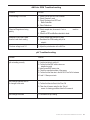
COMMON PROBLEMS . . . . . . . . . . . . . . . . . . . . . . . . . . . . . . . . . . . . . . . . . . . . . . . . . . . . . . . . . . . . . . . . . . . . . . . . . . . . . . . . . . . . . . . . .
REAL TIME CLOCK . . . . . . . . . . . . . . . . . . . . . . . . . . . . . . . . . . . . . . . . . . . . . . . . . . . . . . . . . . . . . . . . . . . . . . . . . . . . . . . . . . . . . . . . . . . . .
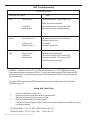
ORP TROUBLESHOOTING . . . . . . . . . . . . . . . . . . . . . . . . . . . . . . . . . . . . . . . . . . . . . . . . . . . . . . . . . . . . . . . . . . . . . . . . . . . . . . . . . . . . . .
USING THE TEST STRIP . . . . . . . . . . . . . . . . . . . . . . . . . . . . . . . . . . . . . . . . . . . . . . . . . . . . . . . . . . . . . . . . . . . . . . . . . . . . . . . . . . . . . . . . .
AKCOLOR PPM TROUBLESHOOTING. . . . . . . . . . . . . . . . . . . . . . . . . . . . . . . . . . . . . . . . . . . . . . . . . . . . . . . . . . . . . . . . . . . . . . . . . . .
pH TROUBLESHOOTING . . . . . . . . . . . . . . . . . . . . . . . . . . . . . . . . . . . . . . . . . . . . . . . . . . . . . . . . . . . . . . . . . . . . . . . . . . . . . . . . . . . . . . .
33
35
35
36
36
37
37
38
39
39
40
40
41
41
SECTION 8 APPENDIXES
UTILITY PASSWORDS 9000-9020 . . . . . . . . . . . . . . . . . . . . . . . . . . . . . . . . . . . . . . . . . . . . . . . . . . . . . . . . . . . . . . . . . . . . . . . . . . . . . . . 42
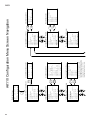
SET-UP DIGITAL FLOW . . . . . . . . . . . . . . . . . . . . . . . . . . . . . . . . . . . . . . . . . . . . . . . . . . . . . . . . . . . . . . . . . . . . . . . . . . . . . . . . . . . . . . . . . 42
PROPORTIONAL FEED. . . . . . . . . . . . . . . . . . . . . . . . . . . . . . . . . . . . . . . . . . . . . . . . . . . . . . . . . . . . . . . . . . . . . . . . . . . . . . . . . . . . . . . . . 42
SECTION 9 WIRING DIAGRAMS
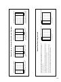
RELAY WIRING DIAGRAMS . . . . . . . . . . . . . . . . . . . . . . . . . . . . . . . . . . . . . . . . . . . . . . . . . . . . . . . . . . . . . . . . . . . . . . . . . . . . . . . . . . . . . 43
SENSOR WIRING DIAGRAMS. . . . . . . . . . . . . . . . . . . . . . . . . . . . . . . . . . . . . . . . . . . . . . . . . . . . . . . . . . . . . . . . . . . . . . . . . . . . . . . . . . . 44
SECTION 10 MENUS
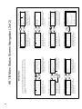
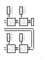
SCREEN NAVIGATION KEYS . . . . . . . . . . . . . . . . . . . . . . . . . . . . . . . . . . . . . . . . . . . . . . . . . . . . . . . . . . . . . . . . . . . . . . . . . . . . . . . . . . . . . . . . . . . . .
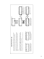
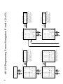
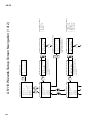
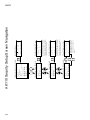
MAIN STATUS SCREEN NAVIGATIONS . . . . . . . . . . . . . . . . . . . . . . . . . . . . . . . . . . . . . . . . . . . . . . . . . . . . . . . . . . . . . . . . . . . . . . . . . .
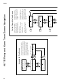
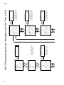
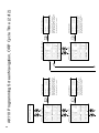
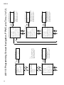
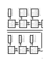
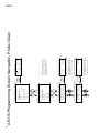
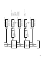
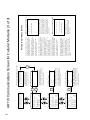
RELAY AND ALARM TIMER SCREEN NAVIGATION . . . . . . . . . . . . . . . . . . . . . . . . . . . . . . . . . . . . . . . . . . . . . . . . . . . . . . . . . . . . . . .
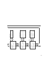
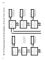
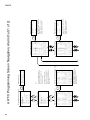
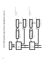
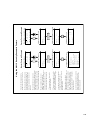
CONFIGURATION MENU SCREEN NAVIGATION . . . . . . . . . . . . . . . . . . . . . . . . . . . . . . . . . . . . . . . . . . . . . . . . . . . . . . . . . . . . . . . . .
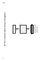
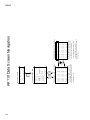
CONTROLLER NAME SCREEN NAVIGATION. . . . . . . . . . . . . . . . . . . . . . . . . . . . . . . . . . . . . . . . . . . . . . . . . . . . . . . . . . . . . . . . . . . . .
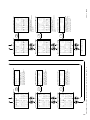
SYSTEM SETUP SCREEN NAVIGATION. . . . . . . . . . . . . . . . . . . . . . . . . . . . . . . . . . . . . . . . . . . . . . . . . . . . . . . . . . . . . . . . . . . . . . . . . .
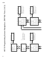
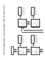
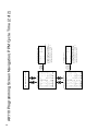
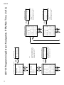
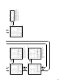
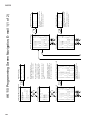
PROGRAMMING SCREEN NAVIGATION , pH MIX TIME . . . . . . . . . . . . . . . . . . . . . . . . . . . . . . . . . . . . . . . . . . . . . . . . . . . . . . . . . .
PROGRAMMING SCREEN NAVIGATION, pH CYCLE TIME. . . . . . . . . . . . . . . . . . . . . . . . . . . . . . . . . . . . . . . . . . . . . . . . . . . . . . . . .
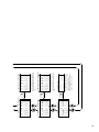
PROGRAMMING SCREEN NAVIGATION, ORP MIX TIME . . . . . . . . . . . . . . . . . . . . . . . . . . . . . . . . . . . . . . . . . . . . . . . . . . . . . . . . .
PROGRAMMING SCREEN NAVIGATION, ORP CYCLE TIME . . . . . . . . . . . . . . . . . . . . . . . . . . . . . . . . . . . . . . . . . . . . . . . . . . . . . . .
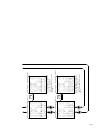
PROGRAMMING SCREEN NAVIGATION, ORP CAL HYPO. . . . . . . . . . . . . . . . . . . . . . . . . . . . . . . . . . . . . . . . . . . . . . . . . . . . . . . . .
PROGRAMMING SCREEN NAVIGATION, PPM CYCLE TIME. . . . . . . . . . . . . . . . . . . . . . . . . . . . . . . . . . . . . . . . . . . . . . . . . . . . . . .
PROGRAMMING SCREEN NAVIGATION, PMM MIX TIME. . . . . . . . . . . . . . . . . . . . . . . . . . . . . . . . . . . . . . . . . . . . . . . . . . . . . . . . .
PROGRAMMING SCREEN NAVIGATION, PROBE CLEAN . . . . . . . . . . . . . . . . . . . . . . . . . . . . . . . . . . . . . . . . . . . . . . . . . . . . . . . . .
PROGRAMMING SCREEN NAVIGATION, HEATER . . . . . . . . . . . . . . . . . . . . . . . . . . . . . . . . . . . . . . . . . . . . . . . . . . . . . . . . . . . . . . . .
PROGRAMMING SCREEN NAVIGATION, ALARM OUT . . . . . . . . . . . . . . . . . . . . . . . . . . . . . . . . . . . . . . . . . . . . . . . . . . . . . . . . . . .
PROGRAMMING SCREEN NAVIGATION, AUX. MAKE-UP (AUTO-FILL) . . . . . . . . . . . . . . . . . . . . . . . . . . . . . . . . . . . . . . . . . . . .
PROGRAMMING SCREEN NAVIGATION, DAILY EVENT. . . . . . . . . . . . . . . . . . . . . . . . . . . . . . . . . . . . . . . . . . . . . . . . . . . . . . . . . . .
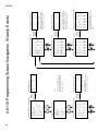
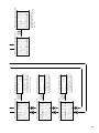
PROGRAMMING SCREEN NAVIGATION, WEEKLY EVENT. . . . . . . . . . . . . . . . . . . . . . . . . . . . . . . . . . . . . . . . . . . . . . . . . . . . . . . . .
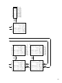
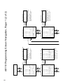
PROGRAMMING SCREEN NAVIGATION, FRONT PANEL ALARM. . . . . . . . . . . . . . . . . . . . . . . . . . . . . . . . . . . . . . . . . . . . . . . . . .
PROGRAMMING SCREEN NAVIGATION, PAGER. . . . . . . . . . . . . . . . . . . . . . . . . . . . . . . . . . . . . . . . . . . . . . . . . . . . . . . . . . . . . . . . .
PROGRAMMING SCREEN NAVIGATION, EMAIL . . . . . . . . . . . . . . . . . . . . . . . . . . . . . . . . . . . . . . . . . . . . . . . . . . . . . . . . . . . . . . . . .
WIZARDS SETUP SCREEN NAVIGATION. . . . . . . . . . . . . . . . . . . . . . . . . . . . . . . . . . . . . . . . . . . . . . . . . . . . . . . . . . . . . . . . . . . . . . . . .
DATA SCREEN NAVIGATION . . . . . . . . . . . . . . . . . . . . . . . . . . . . . . . . . . . . . . . . . . . . . . . . . . . . . . . . . . . . . . . . . . . . . . . . . . . . . . . . . . . .
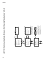
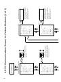
COMMUNICATIONS SCREEN DIAL-UP . . . . . . . . . . . . . . . . . . . . . . . . . . . . . . . . . . . . . . . . . . . . . . . . . . . . . . . . . . . . . . . . . . . . . . . . . .
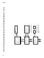
COMMUNICATIONS SCREEN INTERNET MODEMS. . . . . . . . . . . . . . . . . . . . . . . . . . . . . . . . . . . . . . . . . . . . . . . . . . . . . . . . . . . . . .
SECURITY SETUP SCREEN NAVIGATION. . . . . . . . . . . . . . . . . . . . . . . . . . . . . . . . . . . . . . . . . . . . . . . . . . . . . . . . . . . . . . . . . . . . . . . . .
AKCOLOR SCREEN NAVIGATION . . . . . . . . . . . . . . . . . . . . . . . . . . . . . . . . . . . . . . . . . . . . . . . . . . . . . . . . . . . . . . . . . . . . . . . . . . . . . . .
SERVICE SCREEN NAVIGATION . . . . . . . . . . . . . . . . . . . . . . . . . . . . . . . . . . . . . . . . . . . . . . . . . . . . . . . . . . . . . . . . . . . . . . . . . . . . . . . . .
45
46
50
52
54
56
58
60
62
66
70
74
78
82
84
96
90
92
96
96
100
104
108
112
114
118
124
126
128
AK110 CHEMICAL CONTROLLER ILLUSTRATED PARTS LIST . . . . . . . . . . . . . . . . . . . . . . . . . . . . . . . . . . . . . . . . . . . . . . . . . . . . . . . . . . . . . . 130
4
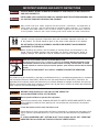
IMPORTANT WARNING AND SAFETY INSTRUCTIONS
SERIOUS BODILY INJURY OR DEATH CAN RESULT IF THIS PRODUCT IS NOT INSTALLED
AND USED CORRECTLY.
INSTALLERS, POOL OPERATORS AND POOL OWNERS MUST READ THESE WARNINGS AND
ALL INSTRUCTIONS BEFORE USING THIS PRODUCT.
Most states and local codes regulate the construction, installation, and operation of
public pools and spas, and the construction of residential pools and spas. It is important
to comply with these codes, many of which directly regulate the installation and use
of this product. Consult your local building and health codes for more information.
IMPORTANT NOTICE - Attention Installer: This Installation and User’s Guide
(“Guide”) contains important information about the installation, operation and safe use
of this product. This Guide should be given to the owner and/or operator of this product.
DO NOT INSTALL THE AK110 CHEMICAL CONTROLLER WHERE IT CAN BE READILY
ACCESSIBLE TO THE PUBLIC.
Before installing this product, read and follow all warning notices and instructions in this
Guide. Failure to follow warnings and instructions can result in severe injury, death, or
property damage. Call (800) 831-7133 for additional free copies of these instructions.
RISK OF ELECTRICAL SHOCK OR ELECTROCUTION:
BEFORE WORKING ON THE AK110 CHEMICAL CONTROLLER: Always disconnect power to the
IntelliChem controller at the circuit breaker before servicing. Failure to do so could
result in death or serious injury to service person, pool users or others due to electric
shock.
BE SURE TO DISCONNECT ALL SUPPLY CONNECTIONS BEFORE SERVICING.
This product must be installed by a licensed or certified electrician or a qualified pool professional in accordance
with the National Electrical Code (NEC), NFPA 70 or the Canadian Electrical Code (CEC), CSA C22.2. All
applicable local installation codes and ordinances must also be adhered to. Improper installation will create an
electrical hazard which could result in death or serious injury to pool users, installers or others due to electrical
shock, and may also cause damage to property.
BEFORE USING YOUR POOL, SPA OR HOT TUB, CHECK THE
pH AND SANITIZER LEVELS OF THE WATER.
Do not permit children to operate this equipment.
When mixing acid with water, ALWAYS ADD ACID TO WATER. NEVER ADD WATER TO ACID.
When adding any chemical to the pool/spa, be sure to follow the manufacturer’s instructions
thoroughly.
DO NOT MIX SODIUM HYPOCHLORITE AND MURATIC ACID
Risk of electrical shock. Connect AK110 Chemical Controller to a ground-fault interrupter-circuit
(GFCI). Contact a qualified electrician if you cannot verify that the receptacle is protected by a
GFCI.
IF “CLEAR OVERFEED LIMIT” SETTING IS SET TO 24 HOURS, DO NOT SET “FEED TIME”
GREATER THAN 20 HOURS AS THIS WILL VOID NSF CERTIFICATION.
ACU-TROL® AK110 Chemical Controller Installation and User's Guide
5
IMPORTANT WARNING AND SAFETY INSTRUCTIONS
WARNING CHEMICAL BURN HAZARD: Make sure all pumps are switched off at the main circuit
breakers at the house before drilling into any pipes. Securely fasten all electrical, water and
chemical lines. Locate chemical feed pumps and chemical storage tanks in a safe and secure
area.
Strictly follow the acid manufacturers safety and handling protocols including hand, body and eye protection
when transferring or handling acid. Safety precautions should be used when handling Muriatic acid to
control pH water levels. Muriatic acid can cause serious body injury and damage pool equipment. Extra
care must be taken when installing, maintaining and operating acid pump feed systems. Acid is dangerous to
handle and should be properly contained, transported, poured, stored, and dispensed.
Check the pH and sanitizer levels of the water before use.
Periodically use an independent pH and Chlorine test kit to verify that pH and chlorine is at a
safe level. If the pH and Oxidation Reduction Potential (ORP) or Flow Cell sensors are broken,
depleted or dirty with oils, lotions, or other contaminants, they can report inaccurate results to the
system causing incorrect water chemistry, which could harm people or equipment.
Check the IntelliChem main status display each day to ensure there are no Alarm messages.
See “Troubleshooting” section for more information.installing, maintaining and operating acid
pump feed systems. Acid is dangerous to handle and should be properly contained, transported,
poured, stored, and dispensed.
GENERAL WARNINGS AND SAFETY PRECATIONS
PLEASEREADTHISUSERMANUALcompletelybeforeinstallingoroperatingtheequipment.TheControllerPoolandSpaChemicalControllerisaClass1productforprotectionagainstelectricshockandaType1productwithregardstodisconnectionofthecontrolcircuits.
Be sure to observe the following safety precautions:
• Do not permit anyone untrained or under the age of 18 to use this product.
• Unit must be properly grounded. • Front panel must be closed before power is applied.
• Always turn OFF main circuit breaker to unit and all equipment before servicing.
• Touching the controller’s internal parts could result in injury and or damage to the controller. In case of a
malfunction, only a qualified technician should repair the controller.
• Risk of Electric Shock. Connect only to a grounding type receptacle protected by a ground-fault circuit interrupter (GFCI).
• Do not bury cord. Route cord to eliminate external damage.
• Becarefulnottodamageanyoftheinsulationonwiresorthepowercord. Shouldthecordbedamaged,returnittoyourdealerfor
a replacement. Continued use could result in fire or electric shock.
• To reduce the risk of electric shock, do not use an extension cord to connect unit to electric supply, provide a
properly located GFCI.
• Never remove or install any cables on the circuit cards when power is applied, damage to the components may
occur.
6
! WARNING
CHEMICAL BURN HAZARD
Make sure pumps are OFF before drilling into pipes.
Securely fasten all electrical, water and chemical lines. Locate chemical feed
pumps and chemical storage tanks in a safe and secure area.
! WARNING
CHEMICAL HAZARD CONDITION
DO NOT TURN CHEMICAL FEED PUMPS ON WHEN BOTH FLOW
CELL VALVES ARE CLOSED.
ACU-TROL® AK110 Chemical Controller Installation and User's Guide
AK110 Pool and Spa Chemical Controller Overview
The AK110PS Pool and Spa Chemical Controller ("Controller") is a microprocessor based modular automation system
capable of continuous local or remote monitoring and control of water chemistry for pool and spa applications. The
Controller will maintain the pH and sanitizer levels of your water system automatically. Customized applications are
possible with the addition of optional expansion modules.
MODULAR: The Controller is designed to grow with the needs of the customer. There are optional modules that can
be installed as the need arises without having to remove the Controller from the wall.
INTERFACE: The Controller uses a built-in keypad with 16 buttons, and an easy to read 80 character liquid crystal
display. The display’s internal back-light provides viewing in low light conditions. The back-light illumination time can be
adjusted to suit the operator.
MENUS: The Controller features easy to use display menus for on screen navigation.
MEMORY: In case of power loss, all set-points and programming are retained in nonvolatile memory. These values will
be protected for a minimum ten (10) years without having power applied.
DATA RECORDING: The Controller has the ability to record data at 2 hour time intervals. Over 1 month of data can be
recorded before filling up the memory. When the memory is full the new data will overwrite the oldest data.
RELAYS: The Controller can control up to three (3) relays. There are various types of relay configurations available to
different types of load requirements.
DISPLAYS: The Controller can display measurements, relay ON/OFF states, length of time that relays have been on
and the alarm status.
SENSORS: The Controller can measure readings and control based on inputs from the following sensors: temperature,
digital flow, pH, ORP, and AKColor PPM.
VOLTAGE: The Controller includes a switch to select the input voltage of 110 or 220 VAC (single or dual phase).
HEALTH: The Controller can be configured to maintain the bacteriological and physiological requirements of state and
local health departments. In addition, the Controller has the capability to be configured such that equipment can be
protected from the effects of improper water balance.
REMOTE MONITORING: The Controller can be easily configured for remote, full duplex communication using an
internal 56K modem and a phone line, or a wireless modem and an internet connection. This feature allows a user
remote access to Controller operations using an MS Windows Based PC and the Acu-Com Software. The Acu-Com
Software is a full featured software package that allows the operator to download recorded data, monitor system
inputs in real time and provides a graphing option that allows for detailed analysis of water system parameters and
performance. In addition, AcuManage II, an online database management system will display data from any internet
enabled Controller.
REMOTE PAGING: With the optional modem installed, the Controller can be programmed to dial out to electronic
paging systems for notifying operators of an alarm condition.
REMOTE EMAILING: With the optional wireless modem installed, the Controller can be programmed to send an email
notifying operators of an alarm condition.
SECURITY: The Controller provides two level security protection based on passwords for both local and remote
interaction.
ACU-TROL® AK110 Chemical Controller Installation and User's Guide
7
SECTION 2
INSTALLATION
Installation Preparation
Inspection: Upon receiving the Controller check the carton carefully. Report any shipping damage to shipping company. Examine the enclosed shipping list and verify that all items are present. Contact Customer Support
(800) 831.7133 if any items are missing or have been damaged. Use care when unpacking equipment to avoid damage or loss of small parts. Verify that the fuses are the correct values and that the voltage select switch is in the proper position.
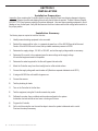
Installation Summary
The following steps are required to install the Controller:
1.
Identify new and existing equipment to be connected.
2.
Decide if the sensors will be in-line, in a separate by-pass line, or if the AK1200 flow cell will be used.
Caution: If the AK1200 flow cell is used, the input water maximum pressure is 25 PSI.
3.
Determine the supply voltage, 110 VAC or 220 VAC, and set the supply voltage switch as necessary.
4.
Determine if the control to the equipment uses the same voltage as the supply voltage.
All controlled equipment must be compatible.
5.
Determine the water-tap points for the flow cell bypass inlet and outlet.
6.Mount the Controller away from direct sunlight and on a flat vertical surface.
7. Connect the supply voltage with main breaker off. (Must be a separate dedicated circuit GFCI).
8.
If using an AK1200 flow cell install the bypass now.
9.
Connect the sensors.
10.
Test the plumbing for leaks.
11.
Turn on the Controller for the first time.
12.
Test the equipment, using the Controller manual relay mode.
13.
Calibrate the probes, then re-calibrate as the probes acclimate to the system. Acclimation can take as little as two hours or as long as 24 hours.
14.Program the Controller.
15.
8
Call or visit the controller over the next few days to insure the system is balanced and in control.
Fine-tune the setup if necessary.
ACU-TROL® AK110 Chemical Controller Installation and User's Guide
Mounting Instructions
Select a location for mounting the Controller, meeting the following recommendations:
1.
Mount at least ten (10) feet from open water.
2.
Mount close enough for the supplied power cord to reach the supply voltage. The Controller will not operate properly without a solid earth ground connection.
!
WARNING
Proper and safe operation requires an earth ground connection.
3.
Supply power must be routed to the Controller in accordance with the applicable codes in the area; the
supplied power cord is not code in some areas.
4.
The installation surface must be solid and vertical. Do not mount the Controller in a horizontal position.
!
WARNING
Keep the Controller out of direct sunlight, inside a room if possible.
Direct sunlight on the Controller will result in inaccurate readings.
A shade screen should be used for outdoor installations.
5.
Maintain adequate clearance for opening the front panel enclosure.
6.
The environment should be free of chemical fumes and excessive heat. The maximum room temperature is should not exceed 110 ºF.
7.
Mount as far as possible from sources of electrical interference.
8.
Install the four mounting feet as desired to the Controller back and prepare the hole to the mounting
surface as desired.
9.
Hold the Controller against the mounting surface with a closed lid and mark the location of the mounting bracket located on the top of the Controller next to the wall. Prepare holes as necessary and secure
Controller using hardware provided.
10.
Mount on a flat surface. Controller box will distort if mounted on an uneven surface.
11.
Pre-install screws with ¼ left out on bottom so that the Controller can slide into them. Install the remaining side screws and tighten.
ACU-TROL® AK110 Chemical Controller Installation and User's Guide
9
Electrical Specifications
The following electrical specifications in the table below must not be exceeded.
ITEM DESCRIPTION LIMIT
Input Voltage
Maximum Input AC Voltage
250 VAC
Input Current
Maximum Input Current
5 Amps (AC)
Output Current
Maximum Current for 3 Relays 110V
5 Amps (AC)
Maximum Combined Current 3 Relays 24V Dry 1 Amp
Temperature
Min./Max. Operating Temperature
30° - 110° F
Standby Current
Current with all Relays OFF, LED ON
50mA (AC) Typical
Current with all Relays OFF, LED OFF
30mA (AC) Typical
Sensor RangepH4.22 - 9.78
ORP0 - 999mV
Temperature32 - 212° F
PPM0 - 9.99 PPM
Digital Flow0 - 9999 GPM
Volume0 - 65,535 Gallons
FlowOpen or Closed
Input Voltage Selection
The Controller will operate on input voltages of 110 VAC or 220 VAC.
The factory jumper setting is for 110 VAC.
The supply power is commonly used to power the feed pumps and
other external loads. If all the loads are 110 VAC then use 110 VAC or if the loads are 220 VAC then use 220 VAC
as the input voltage.
! WARNING
If the Controller is connected to 220 VAC the voltage selection switch must be changed
to 220 VAC before connecting power to the unit or damage will occur.
Note: It is not possible to power the AK110 Chemical Controller with 110 VAC,
and control 220 VAC loads or vise versa.
Connecting Power
For cord connected installations wait to plug the cord in as the last step in the installation. For hard-wired installations
make sure the circuit breaker is off and turn it on as the last step in the installation. Have a licensed electrician perform
the installation to ensure the local codes are met.
10
ACU-TROL® AK110 Chemical Controller Installation and User's Guide
Electrical Loads
The Controller with revision F and greater relay board has the capability of utilizing up to three (3) modular relay boards
that can be purchased in a number of configurations. The Controller is shipped from the factory with three (3) 110 VAC
Normally Open modules installed (Part# 724000050). Listed below are the different types of relay modules that can
be purchased and their function. The correct ones must be ordered based on the load requirements. Check with your
distributor for the proper relay modules for your application.
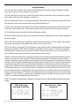
Factory Setting
for input power
115 VAC
Setting for input
power 24VAC
Dry (Switch)
White = No Jumper
Grey = Jumper
Relay Modules
Part #FUNCTION
724000050For control of 110 VAC Normally Open Circuits
(most applications will use this model).
724000060
For control of 110 VAC Normally Closed Circuits.
724000440For control of 110 VAC Single Pole, Double Throw Circuits, with common white and no ground.
The wiring on each board may be different depending on the model that you purchase. Look on the board, check with
your distributor or call Pentair Customer Support at 800-831-7133 with any questions.
!
WARNING
Do not change relay modules when power is applied.
This type of damage is not covered in the warranty.
Do not connect any load not rated for the supply voltage to any of these relays.
TOTAL COMBINED LOADS MUST BE LESS THAN FIVE (5) AMPS
FOR ALL THREE RELAYS.
ACU-TROL® AK110 Chemical Controller Installation and User's Guide
11
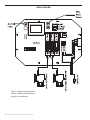
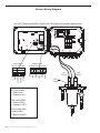
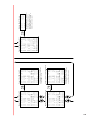
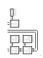
RELAY BOARD
115
Relay 1: Configured for pH control.
Relay 2: Configured for ORP control.
Relay 3: User configured.
12
ACU-TROL® AK110 Chemical Controller Installation and User's Guide
Chemical Feed Pump Location
If unit has not been previously installed, follow the instructions included with the chemical feed pump. Some loads
include power cords already connected to the load and are ready to plug in. If “pigtails” have been ordered with the
Controller simply plug the power cord into the appropriate "pigtail". If "pigtails" are not installed the power cord from the
pump will need to be modified. The list below provides installation recommendations:
1. Mount at least 10 feet from open water.
2.Install the pump below the level of the Controller and away from any other equipment or systems.
This is to reduce any damage to other equipment should the pump leak.
3. Install close enough to the Controller for the feed pump power cords to reach.
4. If "pigtails" are included simply plug in the pumps to the appropriate "pigtail". If pigtails are not installed, cut the electric plugs from the feed pumps and strip and ferrule the ends.
5. Route the power cords to the Controller through the lower fittings and attach to the appropriate relay terminals on the relay circuit board. If the wire ends were striped and not ferruled make sure that no frays of wire are out of the connector as this may lead to a short.
6. Conduit or external plugs can also be used (according to the codes in the local area).
7. When installing metal conduit into the Controller, a ground LUG should be used to connect the conduit to the relay board ground.
Heater Installation
The Controller third relay can control a heater, turning it on and off based on the temperature settings you have
programmed in to the Controller. The heater control portion of the Controller can be used to maintain a constant
temperature or maintain a temperature during operating hours. Even though the Controller is a very accurate and
reliable device, for safety, always use the over-temp device on your heater to prevent overheating.
1. Always install any heater according to the manufacturer's instructions.
2. Mount the Controller at least 10 feet from open water.
3. Install close enough to the Controller for the wiring connections to reach.
4. DO NOT attempt to power the heater with the Controller controller.
5.
A heater unit must always be independently powered, either through a separate cord, or through an external relay like the Acu-Trol HAR1 relay module. (Part# 735000060)
Always use the over-temp device on the heater to prevent overheating.
6.
ACU-TROL® AK110 Chemical Controller Installation and User's Guide
13
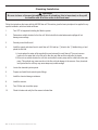
Plumbing Installation
!
WARNING
Be sure to have a licensed plumber perform all plumbing; this is important, as they will
be familiar with all of the codes in the local area.
Follow the instructions that came with the AK1200 flow cell. This section gives the basic principles to be applied for any
specific installation, which are listed as follows:
1. Turn OFF all equipment including the filtration system.
2.
Determine a suitable location for the flow cell. Which should be located where water spillage will not damage surroundings.
3.
Securely mount the flow cell.
4.
Install the supply and return lines for each flow cell. Drill and tap ¼” holes for the ½” flexible tubing or hard plumb the flow cell.
A. Locate where the water will be supplied from and returned for each flow cell. The most common location for the water inlet to the flow cell is after the main filter and the outlet after the heater. B. If there is no suitable location the cell inlet can be after the main pump and the outlet before the main pump. This method may cause a suction in the flow cell and damage to the sensors. If any chemicals are injected into the cell they may cause temporary invalid readings.
Locate the chemical injection points.
6.
Prepare and install the chemical injector fittings.
5.
7.Install the chemical storage containers.
8.
Install the sensors.
9.
Turn ON the main circulation pump.
10. Check for leaks and verify the flow sensor indicates flow.
14
ACU-TROL® AK110 Chemical Controller Installation and User's Guide
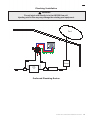
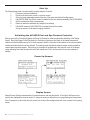
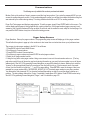
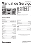
Plumbing Installation
!
WARNING
Do not inject acid directly in to the AK1200 flow cell.
Injecting acid in this way may damage the existing pool equipment.
Water
Sample
Test
Pump
Supply
Return
Pool
Preferred Plumbing Routes
ACU-TROL® AK110 Chemical Controller Installation and User's Guide
15
SECTION 3
HARDWARE
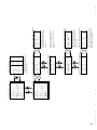
Modules
Modules are the electronic controls and components that make up the Controller.
Each module has a specific function or functions that tell the Controller what information to accept and what information
to display. The modular design of the Controller enables it to interface with many types of modules including Sensor,
Communication, and Relay modules.
Sensor Modules
Sensor modules determine the types of sensors signals the control can recieve. There are three sensor modules
currently available for the Controller.
AK111: pH, ORP, temp and heater control. Calculated PPM can also be displayed (Part# 724000010).
AK112: pH, AKColor(PPM), heater control (Part# 724000380)
AK113SC: pH AKColor(PPM) ORP, Temp (Part # 725000390)
Communication Modules
The Controller has the ability to work with several types of communication modules. The Controller can communicate
with a PC through an RS232 cable, a standard modem, or a wireless modem.
Controller Modem: High-speed modem. (Part # 725000010)
Wireless Modem: The wireless modem allows the Controller to be accessed over the internet from any PC. Wireless modems are a perfect solution for installations without phone lines. Please note that the wireless modem and the standard modem can not be installed in the same Controller.
Relay Modules
The Controller is able to automate nearly any device in your pump room. The Controller uses a relay module to turn
electricity to the device on and off. Each Controller can control up to 3 relay modules. Each relay module can control
one device. Relay modules are available in seven different models. The type of relay module used depends on the
load requirements of the device that is controlled with the relay module. To determine the load requirements, please
consult the instruction manual or the device manufacturer. Any combination of the seven models of relay modules can
be installed in the three available slots on a relay board, as long as the combination does not exceed the combined
maximum current for the relayboard. The combined maximum current for any individual relay board is 5 amps.
16
ACU-TROL® AK110 Chemical Controller Installation and User's Guide
The maximum relay current for the relay board is 5 amps when switching 115 VAC or 220 VAC and 1 amps when
switching 24 VAC.DRY
CONTACTS: These relays act as a dry contact switch only and have no connection to the input VAC. The relay ratings
are 5A and 250 VAC.
115 VAC Normally Closed: These relays supply the input voltage to the load when the relay is in the “OFF” mode. Note
that both VAC inputs are controlled by the relay. The relay ratings are 5A and 250 VAC.
115 VAC Normally Open: These relays supply the input voltage to the load when the relay is in the “ON” mode. Note
that both VAC inputs are controlled by the relay. The relay ratings are 5A and 250 VAC.
115 VAC SPDT: These relays are hard-wired selectable to be either NO (Normally Open) or NC (Normally Closed)
switching of the input voltage. They are always powered, and the wiring will dictate whether the power flows in the on or
off position. The relay ratings are 5A and 250 VAC. The neutral is common for both NO and NC.
24 VAC Normally Closed: These relays supply 24 VAC to the load when the relay is in the “OFF” mode. Note that both
VAC inputs are controlled by the relay. The relay ratings are 1A and 250 VAC.
24 VAC Normally Open: These relays supply 24 VAC to the load when the relay is in the “ON” mode. Note that both
VAC inputs are controlled by the relay. The relay ratings are 1A and 250 VAC.
24 VAC SPDT: These relays are hard-wired selectable to be either NO (Normally Open) or NC (Normally Closed)
switching of the 24 VAC. They are always powered, and the wiring will dictate whether the power flows in the on or off
position. The relay ratings are 1A and 250 VAC. The neutral is common for both NO and NC.
ACU-TROL® AK110 Chemical Controller Installation and User's Guide
17
SECTION 4
AK1200 FLOW CELL
AK1200 Flow Cell
Remove flow cell from shipping carton and make sure all parts are included with AK1200 flow cell.
• 1 – AK1200 Lid
• 1 – Flow switch magnet
• 1 - Sample barb fitting
• 1 - Filter assembly with O-Ring
• 1 - Flow switch with O-Ring, 2’ and 10’ wire lengths available.
• 2 - Mounting screws
• 1 – AK1200 Jar with O-Ring
• 3 - ¼” Valves.
• 4 - ¼” NPT by ½” flex fittings.
• 2 - ¼” plugs.
• 1 - ¼” Close Nipple
• 1 - Teflon Tape
Note that ½” flexible tubing is not included and is supplied by the installer or may be ordered from Acu-Trol.
18
ACU-TROL® AK110 Chemical Controller Installation and User's Guide
1. 2. 3. 4. 5. 6. 7. Flow Cell Assembly
Wrap all four flex fittings with Teflon tape.
Install two flex fittings into two ball valves.
Wrap barb fitting with Teflon tape. Install barb into remaining ball valve.
Wrap both ends of the close-nipple with Teflon tape. Install into the filter assembly using (either end OK). Hand-tighten only.
Install one ball valve into the filter.
Install the filter and remaining ball valves as shown in the figure.
Verify that the flow switch magnet is in the flow cell tube with the large or hat end pointing down.
NOTE: Wrap fittings only twice around with Teflon tape.
Flow Cell Mounting
Select a suitable location for the flow cell meeting the following recommendations:
1. 2. 3. 4. 5. 6. 7. 8. 9. 10. 11. Sensors wires will connect to within ten (10) feet.
Do not mount in direct sunlight. SUNLIGHT WILL CAUSE INACCURATE READINGS.
Water leaks will cause damage! Mount where water does not leak and damage other compentents.
Mount flow cell vertically with provided screws.
Securely fasten all electrical, water and chemical lines.
Locate chemical feed pumps and chemical storage tanks in a safe and secure area.
Maximum operating pressure = 25 psi
Extreme pressure variances may affect readings and can cause damage to the sensors.
Avoid installing the outlet before the main pump as the vacuum may damage the chemical sensors.
Only inject chemicals on the outlet side of the AK1200 Flow Cell
Do not over tighten fitting on flow cell top.
Inlet and Exit Lines
1.
2.
3.
4.
5.
It is essential that the supply line be at a higher pressure than the discharge line so the water will flow through the cell at a steady rate in the right direction. Installing a ball valve in the main circulation line may be required if the pressure is too low.
Inlet should be installed after filter and before heater.
Exit should be installed after heater and as far away from any equipment as possible.
Drill and tap at above locations with 7/16” drill and 1/4” NPT tap. Choose a location on a fitting where the
pipe enters so you are drilling through both the pipe and fitting to get maximum depth of thread.
Install ¼” NPT by ½” flex fittings then route inlet and exit lines.
ACU-TROL® AK110 Chemical Controller Installation and User's Guide
19
Sensors
1. pH and ORP sensors must remain wet at all times. Install the sensors into the flow cell,
HAND-TIGHTEN ONLY and save caps for future use and fill flow cell with water.
2. Route the flow switch wires into the Controller through the strain relief and connect to the Controller.
Wire one (either one) to ground and one to the appropriate input switch.
3. Route the chemical sensors into the Controller through the strain relief and connect to the Controller.
The sensor wires are labeled and the PLUS AND MINUS POLARITY MUST BE OBSERVED.
4. Turn the main pump on and open the valves to test for leaks and the free movement of magnet.
Magnet must be all the way up in order to close the flow switch. 1/4 GPM will push the magnet all the
way up. !
CAUTION
The flow switch is a dry contact only (no current).
Use with any other brand Controller VOIDS WARRANTY.
20
! WARNING:
Make sure all pumps are OFF before drilling into pipes.
Never turn chemical feed pumps ON when both
flow cell valves are closed.
ACU-TROL® AK110 Chemical Controller Installation and User's Guide
SECTION 5
SENSORS
The Controller can accept readings from a wide variety of sensors. The sensors the Controller can read depends on
the sensor module installed in the Controller. Each sensor has its own unique circuitry that is connected directly to the
micro-Controller for measurement. Isolation of each sensor ensures more accurate measurements.
The Controller measures the following sensor measurements with the listed characteristics:
pH - Range: 4.22 to 9.78
ORP - Range: 0 to 999 mV
Temperature - Range: 32 to 212 °F
Flow Switch: This input measures if a switch is open or closed.
! WARNING
Sensors are shipped with a protective cap covering the electrode tip to protect
the sensing element. Sensors should be kept in the protective cap until ready for
installation, if the sponge in the boot becomes dry, wet it with pool water.
Before using the sensor remove the cap.
pH and ORP Sensors
pH electrodes sense the acidity of the water and work with any acid or base. The blue bands on the cables identify the
pH sensors. The red bands on the cables identify ORP sensors. Each sensor is also identified on the sensor body. ORP
electrodes are used to monitor the Oxidation Reduction Potential (ORP is sanitization quality of the water) of a given
solution. The sensing element of the ORP electrode is made of a precious metal such as platinum or gold.
THE POLARITY (+ AND -) OF THE pH AND ORP SENSORS MUST BE OBSERVED. The ORP sensor (+) copper
and the pH sensor (+) copper, and the green leads are (-) polarity labeled. Leave excess wire outside the Controller
enclosure. If the cable is longer than needed, it should be coiled neatly and attached under the Controller enclosure.
DO NOT CUT THE SENSOR WIRES.
Do not stuff excess wire inside the controller as this may cause excess strain
on sensor and relay connections.
ACU-TROL® AK110 Chemical Controller Installation and User's Guide
21
Calculated PPM
If you have an ORP sensor module you can choose to operate the AK110 in Calculated PPM (Parts Per Million) mode.
When in Calculated PPM mode, the Controller uses a special formula to convert the ORP reading from the sensor in to
PPM units. To activate the Calculated PPM mode, select "PPM, Mix Time" or "PPM, Cycle Time" in the wizard section.
Note when you are in Calculated PPM mode ORP will not be displayed on any screens. See page 78 for PPM Cycle
time menu tree.
AKColor PPM Sensor
The AKCOLOR is a colorimetric method chlorine analyzer designed to work in conjunction with most Acu-Trol®
Controllers. The AKColor is capable of measuring the amount of free chlorine present in a body of water. The
colormetric method of measuring PPM is superior to other methods because it is much less sensitive to varying water
conditions, including pH and salinity. The information gathered by the AK Color can be used to control chemical feed
pumps and signal alarm conditions. For more information on the AKColor please see Navigation Screen on page 128
or consult your AKCOLOR installation manual.
Temperature Sensor
The AK10K sensor can be installed to measure/display temperature. The sensor should be installed as close as
possible to where the water comes from the pool. If a temperature probe is installed in the AK1200 flow cell there will be
a temperature variation due to the long tubes and the temperature in the pump room. A common place to install it is in
the small plugged hole in the bottom of the main pump strainer basket.
The sensor uses a special ¼” NPT fitting to hold the stainless steel sensor. A hole should be drilled (7/16”) and tapped
(1/4”) where the water enters the pump room through a fitting to get double the depth to hold the sensor. If installed
outdoors make sure to keep it out of direct sunlight. Route the wires into the Controller through a strain relief and
connect to the temperature input. The red wire goes to T and the black wire to GND.
Flow Sensors
The Controller has the capability of measuring two flow switches in which one or both can be a digital flow sensor.
These inputs are general purpose and can measure any dry contact switch state. This can include flow, pressure,
temperature, digital flow rate and so on.
The typical uses for the flow switches are:
Switch 1: Typically used to indicate flow through the flow cell and it is OK to feed chemicals. If a digital sensor is
used the actual flow rate can be measured and displayed in gallons/liters per hour.
Switch 2: Can be used to measure water level for automatic level control. If a digital sensor is used the actual flow
can be measured and displayed in gallons / liters per hour. NOTE:
To obtain liters per minute the scale factor must be changed to pulses per liter.
22
ACU-TROL® AK110 Chemical Controller Installation and User's Guide
Sensor Care
Contamination of the sensing elements often results in slow response and inaccurate readings. Clean the elements by
the following procedures:
pH and ORP Sensors
1.
Wash electrode tip in a liquid detergent and water. Carefully use a soft bristled toothbrush to wash the electrode tip and white sensing ring.
2.
Rinse after cleaning. To install, place in flow cell according to the diagram and hand tighten.
3.
Make sure the O-ring is installed on sensor.
4.
If the cable is longer than needed, it should be coiled neatly and attached under the cabinet.
pH Sensors Only
5.
Attempt to clean the sensor with liquid detergent first.
6.
If this is not successful, swirl the tip of the sensor in a 5 parts water and 1 part muriatic acid solution for 10 - 20 seconds.
7.
Rinse again and reinstall.
!
WARNING
Do not rub hard the glass element in the sensor or use sand paper or
other polishing material to clean.
HANDLE ELECTRODE CAREFULLY
Sensors contain external and internal glass elements. Do not drop or otherwise
subject the sensor to vibration, physical impact, or freezing conditions.
ANY TYPE OF BREAKAGE IS NOT COVERED UNDER WARRANTY.
Finishing and Testing the Installation
Once the Controller system has been installed with applicable sensors and expansion modules the following steps are
required for final system finishing and testing.
1.
After all wire connections are complete close the panel and tighten the enclosure.
2.
Plug in the Controller and turn on the main breaker. Switch the ON/Off switch to ON.
Up is ON and down is OFF.
3.
Verify that the display is active and displays various introduction/initialization screens.
4.
SENSORS: The first screen displays the sensor readings, verify that they are connected properly.
Example: pH is within 0.5. This is to verify that the pH is connected to the pH input and
the ORP is connected to the ORP input.
5.
FLOW: Verify that the flow switch indicates on (S1ON) and the green flow LED is on. Close the valve
in the flow cell to stop the flow and verify that the Controller indicates no flow (S1OFF) and the flow
LED is off.
6.
LOADS: Leave the valve closed (S1OFF) for this part of the test so that the relay programs will keep relays "automatically" off. Press the Right button 1 time to R1 (ph) OFF and press ENTER to
"manually" turn on the load, verify that the correct load turns on and press enter to turn it off. Press the down arrow to select the next relay and repeat for the other two relays.
ACU-TROL® AK110 Chemical Controller Installation and User's Guide
23
SECTION 6
OPERATION
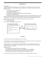
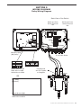
FLOW
INDICATOR LIGHTS
Flow is on when light
is lit.
AK110
POWER
FLOW
Alarm
Indicator Lights
Light is lit when a
warning or alarm
condition occurs.
POWER
INDICATOR LIGHT
Power is on when light is lit.
ALARM
SECURITY
7 8 9
4 5 6
1 2 3
0
SECURITY
INDICATOR LIGHT
Lightislitwhenpassword
protection is active.
Back Enter
Made in USA
110/220 VAC. 5A Disconnect Power Source Before Servicing Unit
ALPHANUMERIC KEYPAD
Usedtoenternumericparametersettings,alphabeticcharacters, and special shortcuts for commonly used menus.
ARROW BUTTONS
Up/ Down/ Left/ Right arrow buttons move you
through the AK110's menus.
Configuration Menu Screen
>Name:Main Pool
System
Programming
Service
Data ( 8:441 )
Communications
Security Setup
Wizards
Serial # 123456
Main Status, cursor at pH value
pH > 7.67-OFF 7.50s
ORP 490 -OFF 700s
_____
69.0f SW1OFFSW2OFF
24
ACU-TROL® AK110 Chemical Controller Installation and User's Guide
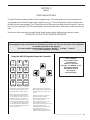
Window Navigation
This section introduces window navigating and how to
edit and modify the Controller settings and programs
using guidelines and examples for selecting and changing
items.
The Controller provides two main screens for user
operations:
1. Display Screen: for monitoring measurements, calibrating and manually turning on relays. This is the list that displays at startup.
2. Menu List: for editing and setup of parameters.
Selecting Items in the Windows
The 16-button touch pad is used to access and modify the different Controller functions:
• Pressing the BACK button on the touch pad will move back one window.
• Pressing the BACK button will toggle between DISPLAY SCREEN and MENU LIST. If the "RED security light" is on a password must be entered to access MENU LIST.
• Pressing the arrow buttons will reposition the cursor on the screen. The UP or DOWN arrow buttons will scroll up or down the screens and the RIGHT and LEFT will move arrows to the RIGHT and LEFT on the screen
See page 48 for more detailed navigation instructions.
!
WARNING
Press 16 Button touch pad with finger pads only. A sharp object such as a
pen or tool will damage button pads.
MAKING CHANGES
To change a parameter move the cursor to the parameter and press the ENTER key. The Controller will then open the
value entry screen for that parameter. The Controller navigation system uses the following considerations:
1. Use the right and left arrows to change to a different digit to enter.
2. Press a number on the keypad to change a digit.
3. Press the left button to add a digit and make the number bigger.
4. Press the ENTER button to save the change.
NOTE
Changes must be saved by pressing the final ENTER.
If ENTER is not pressed as the last step the changes with not be saved.
ACU-TROL® AK110 Chemical Controller Installation and User's Guide
25
Start Up
The following steps need to be performed to properly setup the Controller:
1.
Perform any required calibrations.
2.
Decide to use mixing time control or cycle time control.
3.
Set up the timing parameters based on the size of the water and chemical feeding system.
4.
If the AKRTC (Real Time Clock) module is installed set the time, date and weekday. (Part # 724000280)
5.
Set the overfeed time limits in programming.
6.
Return as needed to recalibrate any changes to the settings
7.
If the AK540 modem (Part# 725000010) is installed, then set the number
of rings to answer on and setup the paging conditions.
Initializing the AK110PS Pool and Spa Chemical Controller
During power-up the Controller will display the Power Up Screens for a few seconds before defaulting to the Display
Screen. During this Power On Self Test mode, the Controller will perform a brief check of its internal systems and
initialize the internal (RAM) memory for Controller operation. Next the Controller will auto detect for the various installed
modules and indicate which ones are detected. The opening screen includes the software version number and will be
required when requesting support. When turning on a number will be displayed in the lower left corner of the display
screen indicating how many seconds until control will actually start. This is to allow time for the sensor readings to
stabilize.
Power Up Screens
Display Screen
Display Screen: Displays measurements of connected sensors and also relay status. To the right of the Sensor readings are also displayed the set point values. To change set points you will need to go to programming and change them
there. Pressing the Up Arrow key when the curser is at the top of the readings screen will move you back to the opening
screen.
26
ACU-TROL® AK110 Chemical Controller Installation and User's Guide
The Display Screen
The DISPLAY SCREEN shows all the current measurements, as well as the
user programmed set points. It allows access to specific types of information
including the current measurements. Press the arrows on the touch pad to
scroll up or down or left or right as indicated by moving the > Cursor on the
screen.
Calibration: Position the cursor to the left of any of the three measurements
and press ENTER to calibrate that sensor. A value entry screen will then be
opened. Enter the calibrated value with the numeric key pad. To save your
change and exit the value entry screen, press the enter button. To clear a
specific calibration press "0" on the touch pad when the cursor is in front of
the value (The reading may not go to a zero reading but it will default to the
sensors uncalibrated reading).
Main Status, cursor
at pH Relay
pH 7.67>OFF 7.50s
ORP 490 -OFF 700s
_____
69.0f SW1OFFSW2OFF
Manually turn on relays: The relays in the Controller are represented on the
display screen next to its corresponding sensor reading. Position the cursor
to the left of the status word (either OFF or ON) and press ENTER to toggle
the relay on and off. The length of time the relay is on is adjustable in the
programming. When the relay is toggled to off the relay
immediately goes back to automatic control and in some cases may turn back
on immediately.
Calibrating Temperature
The temperature sensor is very accurate and should not require calibration. If the calibration is more than a couple
degrees off there may be an installation problem. The most common problems with temperature sensors are listed
below:
1. The most common temperature problem is the temperature is not the same at the sensor as it is in the main body of water. It is also possible the temperature error is different depending on the time of day. Make sure the sensor is not in direct sunlight, and is installed as far into the fitting and as close as possible to the body of water. Evaluate where the sensor is installed.
2. The sensor may be damaged. If the sensor is put in a room of 76°F the resistance should be 10,000 OHM's that can be measured with a standard voltmeter. To calibrate the temperature sensor move the cursor in front of the temperature reading and press ENTER. Enter the measured value. Press ENTER again to save the calibration change.
Calibrating pH
Measure the pH using a standard test kit by taking several readings and averaging the results. To calibrate the pH
sensor move the cursor to pH and press ENTER. Enter the value obtained from the test kit in to the value entry screen.
Press ENTER again to save your changes.
ACU-TROL® AK110 Chemical Controller Installation and User's Guide
27
Calibrating ORP
! WARNING
Always make sure the pH is at the set point before calibrating ORP. Always control
at PPM levels greater than 1.0 PPM when using ORP sensors.
IMPORTANT:
For best results the ORP should be at the ORP set point when calibrating.
For best results the PPM should be at the desired level when calibrating ORP.
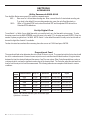
Measure the current PPM using a standard test kit. Calibrating ORP is intuitive and takes a little practice. The following
table can be used to improve the accuracy of the calibration. Follow the recommendations in the table and within a few
days the PPM should be on track. The values of interest are:
Measured PPM: The hand measurement.
Desired PPM: The actual PPM that is desired in the pool.
ORP: The value of ORP that is displayed on the screen.
ORP Set point: The value of ORP that the Controller is trying to achieve.
Hand PPM
ORP Display
Action
Low
Above hand
check
Calibrate to hand check measurement: 10mV per each
PPM Low
Review Setpoints: May need to increase chemical feed
times
At hand check
Below hand
Perfect
check
Above hand
check
At hand check
High
28
Below hand
check
Above hand
check
Calibrate to hand check measurement: 10mV per each
PPM Low
May need to decrease chemical feed times & calibrate to
hand check
No changes
Calibrate to the hand check
May need to decrease chemical feed times & calibrate to
hand check
At hand check
Lower the set point
Below hand
check
Calibrate to hand check measurement: 10mV per each
PPM High
ACU-TROL® AK110 Chemical Controller Installation and User's Guide
Calibrating ORP
EXAMPLE 1: The default set point is 700, the PPM hand measurement is 1.0 (2.0 PPM desired), and the current display shows a measurement of 690 mV. From the above table the hand PPM is low and the ORP is below the set point. The chemical feed times are not high enough for the ORP to reach the set point and should be increased.
EXAMPLE 2: From example 1 change the hand measurement to 4.0 PPM with ORP reading 700mV. From the above table the hand PPM is high and the ORP is below the set point. The ORP should be calibrated to 700 + (4.0 – 2.0) * 10 = 720.To compare ORP measurements to PPM measurements per actual pH readings refer to
Calibrating Calculated PPM
If you have an ORP sensor module and Calculated PPM mode selected. You can calibrate the Calculated PPM in the
following manner. Measure the PPM using a standard test kit. To calibrate the PPM, move the cursor to PPM and
press ENTER. Enter the value obtained from the test kit in the value entry screen. Press ENTER again to save your
changes.
NOTE
You can enter the password 9003 to see the ORP and adjusted ORP being
used for calculated PPM. These ORP values will only be displayed for four
(4) seconds.
! WARNING
Always make sure the pH is at the pH setpoint and PPM is greater than
1.5 PPM before calibrating calculated PPM.
Always control at PPM levels greater than 1.0 PPM when using
ORP sensors.
MANUAL RELAY CONTROL
Display Screens
Position the cursor to the left of the status word and press
ENTER to toggle the relay on and off. The length of time
the relay stays on is adjustable in the programming. When
the relay is toggled to OFF the relay immediately goes back
to automatic control and in some cases may immediately
turn back ON.
Main Status, cursor
at pH Relay
pH 7.67>OFF 7.50s
ORP 490 -OFF 700s
_____
69.0f SW1OFFSW2OFF
ACU-TROL® AK110 Chemical Controller Installation and User's Guide
29
RELAY TIMER DISPLAY
The Relay Timer display indicates the present status of the 8 timers
used in the Controller. The most common use for this screen is to
perform diagnostics on a specific relay or to see how long a relay has
been on. From the DISPLAY SCREEN press the right arrow button
twice. Press the left arrow button to return to readings screen.
Timer Screen, Relay 1 (pH)
pH, Mix
CNT:
STS:OFF
TMR00:00:00
>TD00:00:00
0 S 00:00:00
TOT 0:00
Note: To reset the relay timers to zero use the right button to scroll the cursor beside the information that you want to
reset and then press the ENTER button.
•
TMR: Displays relay timer. Shows time remaining for relay on time.
This timer will be counting with off and on cycles. Counting down when ON cycle, counting up when OFF cycle.
•
TD: Displays the time the MPS has been ON for the current day (ToDay).
•
CNT: Total number of relay cycles since last reset.
•
S: Set overfeed timer, length of relay on time without reaching set point.
•
STS: Status of relay ON, OFF, Set Point Overfeed(SOV), Overfeed(OVF), and Disable (DIS).
•
TOT: Displays the total time the MPS has been ON since last reset in hours:minutes.
SETUP FLOW
To use a switch as a digital flow switch you must first set it up. To enter the setup screen from the DISPLAY SCREEN
move the cursor to the switch "SW_" to be setup and press ENTER. You can enter the number of pulses per gallon
from 1 to 999.9. This second method should only be used for flow meters that generate less than one pulse per gallon.
The highest volume that can be accumulated from the flow rate is 65,535 gallons.
Flow can also be displayed in g/pul and Piezo.
NOTE: Switch 1 is the default flow switch for relay control and should not be used for digital flow if switch 2 is available.
Flow Switch 2 Setup
Flow Switch #2
SW2 K => 8.5 pul/g
g/m
= 35
Total = 256 Clear
NOTE: If k = 0 than g/m = and Total = will not be displayed on the screen.
30
ACU-TROL® AK110 Chemical Controller Installation and User's Guide
To clear the Total, for any switch place the cursor on Clear
and press ENTER.
Flow Switch 2 Setup, Clear Counter
Flow Switch #2
SW2 K => 8.5 pul/g
g/m
= 35
Total = 0
>Clear
Note:
When entering pulses per gallon the Controller will only
update this measurement once every 10 seconds.
Configuration Menu
The Configuration Menu consists of the following:
•
Name: Sets up the name of your aquatic system for easy
identification during communication and on the wireless
data management system. See pages 56 for Controller Name Navigation Menu Tree.
Configuration Menu Screen
>Name:Main Pool
System
Programming
Service
Data ( 8:441 )
•
System: Sets up time, date, weekday, and unit display Communications
(Englishor Metric). See pages 58 or System Set-up Screen Security Setup
Wizards
Navigation.
Serial # 123456
•
Programming: Relay programming for Relays 1, 2, 3, Alarm, and Pagers. See Programming Section for details. See pages 52-109 for Programming Set-up Menus.
•
Service: Clear calibrations, data, or relay timers as part of normal service operations.
•
Data: Sensor readings are recorded at a default 2 hours into data. A total of 441 lines of data can be stored. Press the down arrow key to view data. See page 114 for Data Screen Navigation.
•
Communications: Set up modems, pager numbers and or email addresses. See pages 102-105 for
Programming Screen Navigation Pager 1. See page 116 for Communications Screen for Dail-up
and Internet Modems. See pages 106 for Programming Screen Navigation Email.
•
Security Setup: Sets up passwords, clears passwords, and resets all settings to factory defaults.
See pages 126 for Security Setup Screen Naviagtions.
•
Wizards: Select pre-written programs for common Controller applications.
See pages 110 for Wizards Setup Screen Navigation.
•
Serial #: View the serial number here. The serial number is required when requesting support.
ACU-TROL® AK110 Chemical Controller Installation and User's Guide
31
Name
The Name Setup submenu allows the system controlled by the Controller to be specifically identified on the Controller
and in its communication with other devices. The name of the Controller is particularly useful when using remote
communication devices such as the standard and wireless modem. Naming each aquatic system, pool, or spa will make
it easier to identify each Controller and verify its location before making modifications to the system.
The alphanumeric characters that make up the system name are entered using the touch-pad. You have a full range of
letters, numbers and symbols available to aid you in uniquely identifying each system under your control.
System
Opens a menu where time, date and day can be changed.
•
Time: Time of day; place cursor next to TIME select ENTER to set time in hours, minutes, seconds.
•
Date: Optional with Real Time Clock Module. (Part# 724000280)
Date must be set when Real Time Clock is installed. If not installed date with default to 00:00:00.
•
Day: Optional with Real Time Clock Module. Day must be set when Real Time Clock is installed. If not installed day with default to 00:00:00.
•
Units: Select to toggle between Metric and English units. When metric is selected the date is dd/mm/yy,
when English is selected the date format is mm/dd/yy.
•
Sanitizer: Select between “Cl” (chlorine) and “Br” (bromine).
•
On Delay: Pressing Enter on this line increments (by 15) the number of seconds the relays will be off on
power up.
•
Backlight Time: Select the amount of time the Controller screen backlight will be on each time the control
panel is activated.
•
TempDisplay:Displayswatertemperatureinfarnihietdegrees.Toturntemperaturesensoroff,toggleon/off
and select enter.
•
Reset to Default: Returns Controller to original factory default settings.
32
ACU-TROL® AK110 Chemical Controller Installation and User's Guide
Programming
The Programming menu provides sub-menus used
to configure and view the three output relays, alarm,
and 4 pagers as appropriate. To edit a program use
the up and down arrows to position curser and press
ENTER.
Below are the edit option screens for pH. Use the up
and down arrow to position the curser in front of the
option to be edited.
Edit Settings: Place the cursor to the desired location to
edit the values. Setting a value equal to zero will disable
that command. For example, the Off if Sw Off command
is disabled in the program below. To enable this command change the "No" to "Yes".
Manual Time: The amount of time the relay will turn on during
a manual cycle. This will occur each time the manual cycle is
activated.
Proportional: The percentage of the set point where the
Controller will begin automatically shortening the length of the
feed cycle to prevent the Controller from over shooting the set
point. To turn off the proportional feed function, enter "0" as
the proportional feed percentage.
Programming Setup Screen
>>1:pH, Mix Time
2:ORP, Mix Time
3:Not Used
A:Alarm
P:Pager1
P:Pager2
P:Pager3
P:Pager4
pH Mix Time Programming Screen
ManualTime 00:02:00<
Proportional% 10
On If pH> 7.50
On If pH< 0.00
Off if RLY On 2
On DELAY 00:00:20
On Time 00:01:00
MinTimeOff 00:05:00
Off if Sw1 Off-YES
Off if Sw2 On -NO
SetOvrfeed 00:00:00
Overfeed 01:00:00
Example: 5 is entered as the proportional feed %. This means
that the Controller will automatically shorten the length of the
feed cycle once the measured reading is within 5% of the
set point. If the pH set point is set at 7.50, the proportional
feed will begin to limit the feed cycle at 7.87 and continue
to shorten the feed cycle each time it feeds until set point is
reached. For best results, the proportional feed percentage
should be kept between 0 and 5 percent.
ACU-TROL® AK110 Chemical Controller Installation and User's Guide
33
Programming
On If pH>: Acid Feed: the set point value at which the Controller will begin to feed acid or other pH chemicals to the water
source. Set this value to zero if not using acid to control the pH.
On If pH<: Base Feed: the set point value at which the Controller will begin to feed base or other pH chemicals to the water
source. Set this value to zero if not using base to control the pH.
Off if RLy on(#): Number of relay (1 or 2) will display. Depending on which relay is on the other relay will remain off. Prevents
both relays from coming on at the same time and mixing Chlorine and Muriatic Acid.
On Delay: This is a built in timer which prevents the Controller from prematurely mixing chemicals still in the system or when
suction side chemical feeding is used. This prevents the relay from turning on while chemicals are mixing in the system.
On Time: Maximum amount of time that the Controller will dispense chemicals.
Min Time Off: Minimum amount of time that the Controller will be off before it will dispense any more chemicals, regardless of
the set point reading.
Off if Sw_Off: Tells the Controller not to dispense any chemicals if this switch number is in an OFF condition. This prevents a
large amount of chemicals from being added into the water line as flow of water returns.
Set Point Overfeed: If a relay output is "ON" accumulative for longer than the set point overfeed's maximum time allowed the
reading screen will display a “SOV” (Set Point Overfeed) on relay display. (This is to keep the Controller from continuously
feeding chemicals in case the sensor has a problem or if there is a clog in the feed tubes or you run out of chemicals). This
control condition will automatically reset itself if the sensors set point value is reached.
Overfeed: This value should be set for the maximum accumulated “ON” time that the Controller will be allowed to feed each
chemical in a 24 hour period. If the Controller's “ON” time exceeds the total allowed "ON" time within a 24-hour period the
Controller will disable the associated feed relay, and not feed any more of that chemical until the overfeed timers are cleared
manually, or until the Controller automatically resets the overfeed timers at the end of its 24 hour day. Each relay output used
to control a feed system will have its own overfeed settings. Exceeding the overfeed timers can be set to cause an alarm
condition. If the overfeed time alarm condition persists over a few days you may need to check the chemical container levels,
Controller feeder problems or you may need to increase the overfeed time to a level that will allow the Controller to maintain
the water quality levels within your specified limits. If the system does go into an overfeed condition along with the alarm LED
coming on, it will also display an "OVR" statement in the display screen, for the relay output that was in an overfeed condition.
Overfeed for 01:15:00 or 01:30:00, in case there was a problem with the feeder, chemicals or the sensor that are in overfeed
condition, the Controller would disable feed and alert a problem.
NOTE: The Controller's Overfeed feature is equivalent to the amount of time the chemical feeders will feed during an alarm
condition.
OPR Indicating
Overfeed Condition
pH 7.67>OFF 7.50s
ORP 490 -OVR 700s
69.0f SW1OFFSW2OFF
34
ACU-TROL® AK110 Chemical Controller Installation and User's Guide
Timer Screen, Clear
Overfeed
ORP, Mix TMR00:00:00
>TD01:30:00
CNT: 0 S 00:00:00
STS:OVR TOT 0:00
Programming
To manually reset the Overfeed Timer be sure that the cursor is
beside the TD Reading and press the ENTER button.
This will reset the timer to zero.
Service
All Off 10 min (NO) Press the Enter button to turn all three relays off for 10 minutes. This feature is useful when calibrating. After selecting the display will change to (YES) selecting the line again will remove the "All OFF" condition.
• Clear Calibrations: Clears all previously entered calibrations
• Clear Data: Erases all of the existing data.
• Clear Relay Timers: Resets all timers to zero for all relays.
Data
Sensor readings are recorded every 2 hours into the data log. Up to 12 lines of data can be recorded a day. The
Controller will save up to 441 lines of data in its data log. When the data log is full the oldest records will be over
written.
The default data log includes the day of operation, the hour sequence, and the sensor readings. When used in
conjuction with a real time clock, data includes date and hour and sensor readings. Pressing the down arrow key to
view subsequence data.
When downloading the data with a PC the following information will also be displayed:
Title = MPBPF123: Modem, PC RS232, Front Button pressed, Password entered, Flow S1 on, and relays 1-3 status.
ACU-TROL® AK110 Chemical Controller Installation and User's Guide
35
Communications
The followings are only available if the modem is purchased and installed.
Modem: Sets up the number of rings to answer on and the long hang up time. If you enter the password 9000 you can
access the modem diagnostic screen. On the modem diagnostic screen you will see the modem initialization string that
was returned by the modem during startup. This string should end with the word “OK” for working modems.
Pager Test: Tests pagers and displays paging status. To test the pagers, simply Press ENTER while in this screen. The
screen displays which pager is being paged and its counting down time. If the paged modem (pager company) is not
answering, the Controller modem will hang up within 40 seconds, and the modem is reset, ready for the next page. You
can press the BACK button at any time to cancel the testing process.
Pager Setup Screens
Pager Numbers: Sets up the pager numbers. The programming setup screen will display up to four pager numbers.
This will allow the system to page up to four numbers to alert more than one technician when a pool problem arises.
The process to enter pager numbers in the AK110 is as follows:
1. Press BACK button to reach MAIN Screen.
2. Scroll down to Communications
3. Press ENTER to select Communications
4. Scroll down to pager numbers and press ENTER to select pager numbers
5. Select the #1 pager number location.
6. Using the key pad to enter pager number. Using cursor arrows to move to the next number and so on. (The key
pad works exactly like a cell phone key pad and entering information as you would a phone number in your cell phone
address book). See AK110 Programming Screen Navigation on page 88 for details on alarms. Make sure to enter the
"comma" to allow enough delay time for the modem on the other end to pick up. Each comma is worth 4 seconds
of time. Use the 0 button to toggle the ',', '-', and '#' for pager editing. Press ENTER to save the changes. Here is an
example for a pager number entry: 18005552222,,9014910,,911#. The actual pager number is your phone number.
You determine a code (example: 911 for chemical overfeed) depending on what you want the pager to define as a
problem. The string always ends with a ‘#’ sign. If a mistake is made press UP to delete. Press DOWN to abort entry.
See AK110 Programming Screen Navigatioin, Pager 1 and 2 for details on page 102.
36
ACU-TROL® AK110 Chemical Controller Installation and User's Guide
Email Set-up
Email addresses:
The programming setup screen will display up to four email addresses. This will allow the system to email up to four
addresses to alert more than one technician when a pool problem arises. The process to enter email address in the
AK110 is as follows:
1. Press BACK button to reach MAIN Screen.
2. Scroll down to Communications
3. Press ENTER to select Communications
4. Scroll down to Email addresses and press ENTER to select Email addresses
5. Select the #1 email address location.
6. Using the key pad to enter email address. Using cursor arrows to move to the next letter and so on. (The key
pad works exactly like a cell phone key pad and entering information as you would a phone number in your cell phone
address book). If your email address is to long for the spaces available use the next available email address to complete the address. Add "+02" to the end of the address where you need to break to the next line.
Example: email 1: johndoe@+02
email 2: myserver.com
See page 106 for more detailed email set-up process.
Security
Up to two levels of security may be implemented on the AK110 Controller.
1. Master Password: The master password enables access to all controller functions and menus. A master password
may be implemented alone or in conjuntion with a service password.
2. Service Password: The more limited Service password allows access to sensor calibrations screens from the
Main Status Screen. A service password may be implemented only after a master password has been implemented.
Passwords consist of up to nine digits.
Password restrictions:
1. The password may not be begin with a zero (0) as the first digit.
2. The security password must be in the range of "1" and "8999" and "9011 and "999999999".
The numbers 9000-9010 are reserved for technical support purposes and may not be used.
3. A master password is required for should a wireless modem be installed in the AK110.
See page 126 for the AK110 Security Set-up Screen Navigation for more detailed security set-up process.
ACU-TROL® AK110 Chemical Controller Installation and User's Guide
37
Wizards
When leaving an editing screen you will need to confirm the changes by pressing “9” or cancel by pressing press "7".
Also after making any changes be sure to press the "Back" button until you reach the main menu screen. Otherwise
your changes will not be saved.
The following list shows all the "Wizards" available with the Controller:
Control options for pH Relay 1
1.
pH, Mix Time – use to control a pH feed system.
2.
pH, Cycle Time – use to control a pH feed system.
3.
Not Used – use to disable this relay
Control options for ORP/PPM Relay 2
1.
ORP/PPM, Mix Time – use to control a sanitizer feed system.
2.
ORP/PPM, Cycle Time – use to control a sanitizer feed system.
3.
ORP, Cal Hypo - use to control Cal Hypo feed system
4. Not Used - select to disable this relay.
5. PPM, Mix time - use the calculated PPM features
6. PPM, Cycle time, use the calculated PPM features
Control options for Relay 3
1. Not Used - select to disable this relay.
2. Probe Clean - use to introduce acid for a short time to clean sensors.
3. Heater - Used to control temperature with an external heater.
4. Alarm Out - external alarm control.
5. pH, Mix Time - used for additional pH control (i.e. when both Acid and Base are needed.
6. pH, Cycle Time - optional method see program.
7. AUX: Make UP - control a make-up water system (auto fill).
8. Daily - turns on relay once per day
9. Weekly - turns on relay once per day on selected day(s) of the week.
10. ORP/PPM Mix Time - use for additional sanitizer control
(i.e. when a liquid feed system is used to back up a salt generator).
11. ORP/PPM, Cycle Time - optional method see program.
Control options for Pager/Email 1-4
1. Pager 1-4/Email 1-4
2. Not Used
See page 110 for the AK110 Wizards Setup Screen Navigation
38
ACU-TROL® AK110 Chemical Controller Installation and User's Guide
SECTION 7
TROUBLESHOOTING
COMMON PROBLEMS
PART
Alarm
Flow Cell
PROBLEM
High pH alarm on
Magnet will not go up
SOLUTION #1
SOLUTION #2
Increase ON time (CO2) Check chemical tank
= slower reaction,
and make sure it is
needs more time ON.
Clean filter on flow cell.
not empty.
Back wash main filter
or increase flow.
Reduce flow through
flow cell.
ORP/pH
Probe
Readings bounce
Clean probe, check
ground on input power.
Flow Switch
Not working
Check for magnet.
Alarm
Overfeed alarm on
Increase overfeed time.
Program
Relay 1 & 2 not
turning ON but work
manually
Make sure flow switch
is closed. Verfiy that
the green flow light is
turned on.
Check for debris in
flow cell.
Make sure feeder is
working properly.
Check set points.
The Real Time Clock
The Real Time Clock (RTC) is an optional module (PN# 724000280) that allows time display and time stamps in the data
log. The Controller will automatically detect the real time clock when it is installed. The real time clock is battery powered,
with a minimum of 5 years battery life.
ACU-TROL® AK110 Chemical Controller Installation and User's Guide
39
ORP Troubleshooting
ORP Calibration Actions
Hand PPM ORP Display
Action
Low
Above Set point
At Set point
Below Set point
Cal to below set point: 10mV per each PPM Perfect
Above Set point > 6
At Set point ±5
Below Set point >6
May need to decrease chemical feed times.
Calibrate to the set point.
No changes
Calibrate to the set point.
High
Above Set point
At Set point
Below Set point
Decrease chemical feed times.
Cal to above set point:10mV per each PPM
Cal to above set point: 10mV per each PPM Check flow and/or clean sensor.
Check flow and/or clean sensor.
Cal to below set point: 10mV per each PPM
May need to increase chemical feed times.
EXAMPLE: The default set point is 700, the PPM hand measurement is 1.0 (2.0 PPM desired), and the
current display shows a measurement of 690 mV. From the above table the hand PPM is low and the ORP
is below the set point. The chemical feed times are not high enough for the ORP to reach the set point and
should be increased.
To compare ORP measurements to PPM measurements per actual pH readings refer to the calculated
PPM chart on page 131.
Using the Test Strip
1.
2.
3.
4.
40
Remove all wires from the sensor card.
Insert test strip into the green terminal bar on the sensor card.
Match the pH test strip side to the sensor card side
Reset the calibrations with the test strip installed.
Call Acu-Trol Technical Support at 800-273-4667 with the sensor readings if your results do not match the following readings:
ORP 90350-28ApH = 7.65-7.75 ORP = 485-500 Temp = 68.0-71.0
PPM 90350-35ApH = 7.65-7.75 Color = TBD Temp = 68.0-71.0
ACU-TROL® AK110 Chemical Controller Installation and User's Guide
AKColor PPM Troubleshooting
ProblemSolution
PPM Reading is 0 or 9.99
1. Check Flow to AKColor Flow Chamber
2. Check Chemical Levels
3. Check Discharge from DPD and
Buffer Solenoids
4. Clear Calibrations
Chemical Reagents are being
1. Check sample rate, decrease to 5 min or quicklygreater.
2. Check the DPD and Buffer solenoids for leaks
used too
Measured PPM Level is lower
1. Check sample flow solenoid for leaks
than the hand check reading
2. Recalibrate the PPM reading with pH at
setpoint.
The clear voltage is not 3.5
1. Adjust the potentiometer in the AKColor
pH Troubleshooting
ProblemSolution
pH not reading correctly
1. Use the test strip to verify pH
2. Confirm that the BNC sensor wires are
installed correctly
3. Install a new BNC sensor wire.
4. Check the manufacture date of the sensor
5. Confirm that the flow rate in the AK1200 Flow Cell is between
0.5 and 1.5 liters per minute.
pH readings response slow to
to changes in the water
1. Confirm that there is flow in the Flow Cell 2. Clean the pH sensor using the Acu-Trol pH
sensor or cleaning procedure listed in this manual.
pH readings inaccurate
1. Recalibrate the pH reading
ACU-TROL® AK110 Chemical Controller Installation and User's Guide
41
SECTION 8
APPENDIXES
Utility Passwords 9000-9010
From the Main Status screen press [4] to enter the password screen.
9001 – Enter once for 1-second data recording rate. Enter a second time for 5-minute data recording rate.
To go back to the default 2-hour recording sample rate, power the unit off and then back on.
9003 – When in “Calculated PPM” mode, shows the actual ORP and the adjusted ORP derived from Calculated PPM calibrations.
Set Up Digital Flow
To use Switch 1 or Switch 2 as a digital flow switch you must first set it up in the flow switch set-up screen. To enter
the setup screen from the MAIN SCREEN, move the cursor to the switch “S” to be setup and press ENTER. Enter the
number of pulses per gallon from 0 to 999.9. NOTE: Switch 1 is the default flow switch for relay control and should not
be used for digital flow if switch 2 is available.
To clear the total accumulate flow counter, place the cursor to CLEAR and press ENTER.
Proportional Feed
The proportional feed value determines the ratio of feed ON time in a cycle. The general principle is that a relay should
be on for a reduced amount of time as it nears set point so as to minimize chemical feed overshoot. A lag time exists
between the time the chemical feeds and the sensors "read" the new values. Older Controllers would have a relay on
continuously which can lead to significant overshooting of the chemical feed. The Controller adjust the ratio based on
how far from the set point is from the measurement. The following tables shows examples of feed times for various
conditions:
Set
Point
700
700
700
700
700
700
Measurement
Prop %
630
631
698
665
100
699
Actual On
ACU-TROL® AK110 Chemical Controller Installation and User's Guide
Cycle
10% 00:06:0000:00:0000:06:00
10% 00:05:5400:00:0600:06:00
10% 00:00:0600:05:5400:06:00
10% 00:03:0000:03:0000:06:00
10% 00:05:0600:00:5400:06:00
10% 00:06:0000:00:0000:06:00
Table 3. ORP Control with the Cycle Time control type.
Cycle time = 6 minutes
42
Actual Off
SECTION 9
WIRING DIAGRAMS
Relay Wiring Diagram
Back View of the Switch
Black wire from
Green Terminal
Bar
Black wire to
Power
Supply
White wire from
Green Terminal
Bar
White Wire to
Power Supply
White to Power Supply
Black to Power Supply
Ground
Normally Open
(NO) Relay
Green Wire To GND
Black Wire to NOB
White Wire to NOW
To 110 VAC Outlet
Use Optional
Acu-Trol Pigtails
or Gangbox
Sanitizer
Feed
Pump
OR
Normally Closed
(NC) Relay
(Optional)
Acid
Feed
Pump
Green Wire to GND
Black Wire to NCB
White Wire to NCW
ACU-TROL® AK110 Chemical Controller Installation and User's Guide
43
Sensor Wiring Diagram
AK110PS Chemical Controller Top View AK110PS Chemical Controller Bottom View
pH Sensor Wires
= Green to pH = Copper to pH +
ORP Sensor Wires
= Green to ORP = Copper to ORP +
Flow Switch Wires
= Red to GND
= Black to Switch 1
44
ACU-TROL® AK110 Chemical Controller Installation and User's Guide
TEMP
GND
ORP +
ORP -
pH +
Sensor Card
Green Terminal Bar
pH -
+12
GND
Switch 2
Switch 1
GND
Control Board
Green Terminal Bar
pH
Sensor
Flow
Switch
ORP
Sensor
Enter
SECTION 10
ntroller Name Setup Screen
1
Main Pool
U
v-Cancel Back-Ins
MENUS
SCREEN NAVIGATION KEYS
e the AK110 keypad to enter in a
w controller name. The controller
me may consist of a maximum of
For basic Controller operations, follow the screen navigation keys. The arrows guide you to each level and provide
alphanumeric characters.
ss the down arrow you
key toexamples
return
of the information based on the condition of your pool. The actual information on the Controller screen
he configuration menu.
will differ from the menu examples. The LCD back-light turns off following a user-defined period of inactivity. Press any
key to turn the on back-light. The LCD screen displays 4 horizontal rows at a time. Many menus consist of five or more
lines.
Use the up or down arrow keys to navigate through longer menus to display additional menu options on-screen.
PLEASE CALL 800-831-7133 FOR TECHNICAL ASSISTANCE.
NOTE:
The keypads on the mounted AK110 Chemical Controller do not have the letter of the alphabet
or numbers printed on the keypad.
The some models curser keys do not have "Delete", "To Right", "Cancel"
or "To Left" printed on the keys.
Using the AK110 Keypad to Name the Controller
7
8
9
PQRS
TUV
WXY Z
4
5
6
GH I
1
JKL
2
MNO
3
!$%^&*+
AB C
DEF
0
BACK
ENTER
Insert
Confirm
,-#.@_
Each numeric key is associated with three
or more letters ofthe alphabet, or with
punctuation and other special characters.
Successive keypresses cycle through the
various characters associated with each
key. For instance, press the [5] key once
to display the number "5" on-screen.
Press it a secondtime (while the cursor is
in the same position) to display the letter
"J". The third keypress displays the letter
"K" and the fourth keypress displays the
letter "L". Press thekey one more time to
return to the number "5".
DELETE
R
I
G
H
T
L
E
F
T
Press "ENTER"
at the end of each
programming
session to save the
changes. If "ENTER" is not
pressed the AK110
will default back to
the original
saved changes.
CANCEL
Each of the arrow keys as well as the
[Back] and [Enter] keys perform specific
functions within the Controller Name
Screen.
Press the up arrow key to delete the
character at the cursor position.
Press the left arrow key to move the
cursor one space to the left.
Press the right arrow key to move the
cursor one space to the right.
Press the down arrow key to cancel out of
the controller naming process.
Press the [Back] key to insert a blank
space at the cursor position.
Press the [Enter] key to confirm the
controller name as displayed on-screen.
ACU-TROL® AK110 Chemical Controller Installation and User's Guide
45
46
Configuration Menu Screen
>Name:Main Pool
System
Programming
Service
Data (
8:441 )
Communications
Security Setup
Wizards
Serial # 123456
Back
Enter
Enter
Main Status, cursor at pH value
pH > 7.67-OFF 7.50s
ORP
490 -OFF 700s
_____
69.0f SW1OFFSW2OFF
Main Status, cursor at ORP value
pH
7.67-OFF 7.50s
ORP > 490 –OFF 700s
_____
69.0f SW1OFFSW2OFF
"Any"
Key
Version Control Screen
Acu-Trol, SN123456
Swimming Pool
Automatic Controller
AK110E7, 07/22/08
Use the keypad to enter the
calibrated ORP value.
Press the [Enter] key to confirm or
the down arrow key to cancel.
Calibration Screen, ORP
Enter new value
Current:
490
490
v-Cancel
^
Press the [Enter] key to manually
turn the control relay on or off. If
no flow is detected, a warning /
verification screenwill first appear.
Main Status, pH Relay turned On
pH
7.67>ON 7.50s
ORP
490 -OFF 700s
_____
69.0f SW1OFFSW2OFF
Enter
Main Status, pH Relay is Off
pH
7.67>OFF 7.50s
ORP
490 -OFF 700s
_____
69.0f SW1OFFSW2OFF
Use the keypad to enter the
calibrated pH value.
Press the [Enter] key to confirm or
the down arrow key to cancel.
Calibration Screen, pH
Enter new value
Current:
7.67
7.67
v-Cancel
^
Back
To Timer Screen, pH. Refer to
AK110 Relay and Alarm Timer
Screen Navigat ion
The LCD screen displays 4 horizontal
rows at a time. Many menus consist of 5
or more lines. Use the up and down
arrow keys to navigate through longer
menus to display additional menu options
on-screen.
Note:
The LCD Backlight turns off following a
user-defined periodof inactivity. Press
any key to turn the backlight on.
AK110 Main Status Screen Navigation (1 of 2)
10.1
47
Main Status, Switch 2 Status
pH
7.67-OFF 7.50s
ORP
490 –OFF 700s
_____
69.0f SW1OFF>W2OFF
Main Status, Switch 1 Status
pH
7.67-OFF 7.50s
ORP
490 –OFF 700s
_____
69.0f >W1OFFSW2OFF
Back
Enter
Back
Enter
Main Status, cursor at Temperature
pH
7.67-OFF 7.50s
ORP
490 –OFF 700s
Enter
_____
>69.0f SW1OFFSW2OFF
69.0f SW1OFFSW2OFF
v-Cancel
^
Clear
Flow Switch 2 Setup
Flow Switch #2
SW2 K => 0.0 pul/g
Clear
Flow Switch 1 Setup
Flow Switch #1
SW1 K => 0.0 pul/g
Use the keypad to enter the
calibrated Temperature.
Press the [Enter] key to confirm or
the down arrow key to cancel.
Calibration Screen, Temperature
Enter new value
Current:
69.0
69.0
v-Cancel
^
Press the [Enter] key to manually
turn the control relay on or off. If
no flow is detected, a warning /
verification screenwill first appear.
Main Status, ORP Relay turned On
pH
7.67-OFF 7.50s
ORP
490 >ON
700s
_____
69.0f SW1OFFSW2OFF
Enter
Main Status, ORP Relay is Off
pH
7.67-OFF 7.50s
ORP
490 >OFF 700s
_____
69.0f SW1OFFSW2OFF
Use the keypad to enter the
calibrated ORP value.
Press the [Enter] key to confirm or
the down arrow key to cancel.
Back
To Timer Screen, pH. Refer to
AK110 Relay and Alarm Timer
Screen Navigat ion
48
Press the [4] key to go to the
Diagnostics Password Screen.
Press the [Back] key to return to the
Main Status Screen.
Main Status, cursor anywhere
pH > 7.67-OFF 7.50s
ORP
490 -OFF 700s
_____
69.0f SW1OFFSW2OFF
Move the cursor to a sensor
measurement value and
press the [0] key to go to the
Reset Calibration Screen.
Back
4
9
or
7
0
Press the [Back] key to go to the
Configuration Menu Sc reen.
Press the [Back] key once again to
return to the Main Status Screen.
The Diagnostics Password Screen
is intended for use by Acu-Trol
factory and authorized product
support personnel only.
Enter:
v-Cancel
Main Status, cursor anywhere
pH > 7.67-OFF 7.50s
ORP
490 -OFF 700s
_____
69.0f SW1OFFSW2OFF
Press the left arrow key to go to the
AKColor Status Screen.
Press the [Back] key to return to
the Main Status Screen.
Diagnostics Password Screen
Enter Password
Press the [9] key to reset the
selected calibration offset to
zero or the [7] key to cancel.
Reset Calibration Screen
-Confirm Changes
-Reset current calib
ration?
NO:7
9:Yes
Main Status, cursor on value
pH > 7.67-OFF 7.50s
ORP
490 -OFF 700s
_____
69.0f SW1OFFSW2OFF
Main Status, cursor on the far left
pH > 7.67-OFF 7.50s
PPM
2.65-OFF 2.00s
_____
69.0f SW1OFFSW2OFF
Press the [9] key to go to the
System Information Scr een.
Press "any" key to return to the
Main Status Screen.
The Version Control Screen
displays identifying unit information
including the serial number and the
installed firmware revision.
Press the up arrow key to go to the
Version Control Screen.
Press "any" key to return to the
Main Status Screen.
"Any"
Key
Main Status, cursor anywhere
pH > 7.67-OFF 7.50s
ORP
490 -OFF 700s
_____
69.0f SW1OFFSW2OFF
Press the [6] key to go to the
Modem Diagnostics Scr een.
Press the [Back] key to return to the
Main Status Screen.
Main Status, cursor anywhere
pH > 7.67-OFF 7.50s
ORP
490 -OFF 700s
_____
69.0f SW1OFFSW2OFF
Version Control Screen
Acu-Trol, SN123456
Swimming Pool
Automatic Controller
AK110E7, 07/22/08
Main Status, cursor at top row
pH > 7.67-OFF 7.50s
ORP
490 -OFF 700s
_____
69.0f SW1OFFSW2OFF
A numer of screens may be quickly accessed direcly through the Main Status
Screen. The primary purpose of thesescreens is to conveniently provide system
identification, configuration and diagnostic information to the user or to service
personnel.
Shortcut Keys
Back
Back
"Any"
Key
9
Back
6
Configuration Menu Screen
>Name:Main Pool
System
Programming
Service
Data (
8:441 )
Communications
Security Setup
Wizards
Serial # 123456
An optional colorimetric interface
sensor card must be installed in the
AK110 in order for the AKColor™
Status Screen to be accessable.
AKColor™ Status Screen
FREE= 2.65
75/240
MixingDPD
lvl= 90%
CLRv= 3.48 v= 1.98
The System Information Sc reen
displays unit information such as
total unit on-time and internal
system counters.
System Information Screen
TotalON
12:34hrs
MemoryWR
1
Watchdog
0
0
0
0
An optional modem must be
installed in the AK110 in order for
the Modem Diagnostics Scr een to
display pertinent data.
Modem Diagnostics Screen
+++ATH OK AT&F&C1&D1
&K0S8=4 OK _
Pager
0PgD:
0
Sts
0 6789
0
AK110 Main Status Screen Navigation (2 of 2)
49
If the AK110 is configured to display
metric units of measurement, the
flow sensor values will be displayed
in liters rather than gallons.
Once Flow Switch 2 has been
configured to operate with a digital
flow sensor, the measured flow rate
is displaed in the "SW2" position.
AK110 Main Status Screen Navigation, Rev 3
Flow Switch 2 Setup, Metric Units
Flow Switch #2
SW2 K =
3.6 pul/l
l/m
=
83
Total = 372
>Clear
Main Status, Switch 2 Flow Rate
pH > 7.67-OFF 7.50s
ORP
490 –OFF 700s
_____
69.0f SW1ON FM
35
In this example, Flow Switch 2 is configured to operatewith a digital flow meter.
To set up a flow switch input to operate with a digital flow meter, enter in the
sensor K-factor. The flow rate is displayed on-screen as gallons per minute (g/m)
or as liters per minute (l/m). Furthermore,the accumulated volume is tallied and
displayed (in gallons or in liters) as the "Total" volume.
Assigning a K-factor of "0.0" to a flowswitch allows it to operate as a simple on/
off flow switch. As Flow Switch 1 functions as the defa ult flow switch for relay
control, it is recommended thatit remain configured as a simple on/off flow
switch.
The two flow switch inputs are, in the default configuration, set up as simple on/
off switches. One or both of these flow switch inputs may be configured to
operate with a digital flow meter to measure the flow rate through a pipe.
Digital Flow Meter Setup
Enter
Enter
The unit "g/m" represents the
measured flow rate. "Total" is the
accumulated volume, as calculated
by the flow rate and the K-factor.
Flow Switch 2 Setup, Clear Counter
Flow Switch #2
SW2 K =
8.5 pul/g
Enter
g/m
=
35
Total = 256
>Clear
Clear
Flow Switch 2 Setup, K-Factor
Flow Switch #2
SW2 K => 0.0 pul/g
Back
Main Status, Cursor at Flow Switch 2
pH
7.67-OFF 7.50s
ORP
490 –OFF 700s
_____
69.0f SW1OFF>W2OFF
Press the [Enter] key to reset the
accumulated volume counter to
zero.
21 Aug 2008
Switch 2 Setup, Clear Counter
Flow Switch #2
SW2 K =
8.5 pul/g
g/m
=
35
Total = 0
>Clear
Use the keypad to enter the K-factor
for the installed flow meter.
Press the [Enter] key to confirm or
the down arrow key to cancel.
Flow Switch K-Factor Screen
Enter new value
Current:
0.0
0.0
v-Cancel
^
50
Back
Back
Timer Screen, pH Relay
pH, Mix TMR00:00:00
>TD00:00:00
CNT:
0 S 00:00:00
STS:OFF TOT
0:00
Navigating Within the Timer Screen
Main Status, ORP Relay Status
pH
7.67-OFF 7.50s
ORP
490 >OFF 700s
_____
69.0f SW1OFFSW2OFF
Main Status, pH Relay Status
pH
7.67>OFF 7.50s
ORP
490 -OFF 700s
_____
69.0f SW1OFFSW2OFF
Main Status, cursor at pH value
pH > 7.67-OFF 7.50s
ORP
490 -OFF 700s
_____
69.0f SW1OFFSW2OFF
Timer Screens can be accessed from the
Main Status Screen. Press the right arrow
key to move the cursor to the status indicator
of relay 1, 2, or 3 (if configured.) Press the
right arrow key again to access the pH Timer
Screen. From there, press the up or down
arrow keys to navigate to additional timer
screens (see "CyclingThrough the Timer
Screens" at right).
Accessing the Timer Screens
6
7
8
Each of the Timer Screens
corresponds to a number, from
[1] to [8]. To jump directly to a
specific Timer Screen, press the
keypad number associated with
that device. For instance, to jump
to the Alarm Timer Screen, press
the [4] key.
The eight Timer Screens are
arranged in a specific sequence.
Press the up or down arrow keys
to cycle from one Timer Screen
to another.
Timer Screen, Pager / E-mail 1
Pager1
TMR00:00:00
Timer Screen, Pager / E-mail 2
Pager2
TMR00:00:00
>TD00:00:00
CNT:
0 S 00:00:00
STS:OFF TOT
0:00
Timer Screen, Pager / E-mail 3
Pager3
TMR00:00:00
>TD00:00:00
CNT:
0 S 00:00:00
STS:OFF TOT
0:00
Timer Screen, Pager / E-mail 4
Pager4
TMR00:00:00
>TD00:00:00
CNT:
0 S 00:00:00
STS:OFF TOT
0:00
From any Timer Screen, press the
[Back] key to return to the Main
Status Screen.
If relay 3 has not been configured,
the Timer Screen for that relay
will appear blank.
There are a total of eight Timer
Screens. One Timer Screen is
available for each of the three
relays, one for the front panel
alarm, and one for each of the four
pager/e-mail devices.
Cycling Through the Timer Screens
AK110 Relay and Alarm Timer Screen Navigation
10.2
51
TD:
CNT:
S:
TOT:
Timer Screen, Total Time (TOT)
pH, Mix TMR00:09:01
TD00:23:45
CNT: 1234 S 02:34:56
STS:OFF >TOT
12:34
TMR00:09:01
TD00:23:45
CNT: 1234>S 02:34:56
STS:OFF TOT
12:34
pH, Mix
Timer Screen, Set Overfeed (S)
Timer Screen, Count (CNT)
pH, Mix TMR00:09:01
TD00:23:45
CNT:>1234 S 02:34:56
STS:OFF TOT
12:34
Timer Screen, Today (TD)
pH, Mix TMR00:09:01
>TD00:23:45
CNT: 1234 S 02:34:56
STS:OFF TOT
12:34
Accumulated on-time for the day.
Number of relay cycles since last reset.
Relay on-time without reaching setpoint.
Total on-time since the last reset.
Use the right arrow key to navigate within
the Timer Screen. There four timer cursor
positions to cycle through:
Enter
Enter
Enter
Enter
Reset Timer, Total Time (TOT)
pH, Mix TMR00:09:01
TD00:23:45
CNT: 1234 S 02:34:56
STS:OFF >TOT
0:00
Reset Timer, Set Overfeed (S)
pH, Mix TMR00:09:01
TD00:23:45
CNT: 1234>S 00:00:00
STS:OFF TOT
12:34
Reset Timer, Count (CNT)
pH, Mix TMR00:09:01
TD00:23:45
CNT:>
0 S 02:34:56
STS:OFF TOT
12:34
Reset Timer, Today (TD)
pH, Mix TMR00:09:01
>TD00:00:00
CNT: 1234 S 02:34:56
STS:OFF TOT
12:34
From any Timer Screen, press the [Back] key
to return to the Main Status Screen.
Each of the four selectable timers can be
manually reset to zero. To reset a specific
timer, press the right arrow key to position
the cursor next to thetimer, then press the
[Enter] key.
Navigating Within the Timer Screen
1
2
3
4
5
TOT
0:00
Timer Screen, Relay 1 (pH)
pH, Mix TMR00:00:00
>TD00:00:00
CNT:
0 S 00:00:00
STS:OFF TOT
0:00
Timer Screen, Relay 2 (ORP)
ORP, Mix TMR00:00:00
>TD00:00:00
CNT:
0 S 00:00:00
STS:OFF TOT
0:00
Timer Screen, Relay 3 (Optional)
Relay3
TMR00:00:00
>TD00:00:00
CNT:
0 S 00:00:00
STS:OFF TOT
0:00
Timer Screen, Alarm
Alarm
TMR00:00:00
>TD00:00:00
CNT:
0 S 00:00:00
STS:OFF TOT
0:00
Timer Screen, Pager / E-mail 1
Pager1
TMR00:00:00
>TD00:00:00
CNT:
0 S 00:00:00
STS:OFF TOT
0:00
STS:OFF
52
Configuration Menu, Programming
Name:Main Pool
System
>Programming
Service
Data (
8:441 )
Communications
Security Setup
Wizards
Serial # 123456
Back
Enter
Back
The menu items that appear on the
Programming Setup Scre en will vary
in accordance with the user-specified
configuration as well as with the
installed modem and sensor cards.
Programming Setup Screen
>1:pH, Mix Time
2:ORP, Mix Time
3:Not Used
A:Alarm
P:Pager1
P:Pager2
P:Pager3
P:Pager4
System Setup Screen
>Time: 12:34:56
Date: 07/04/08
Day : Friday
Units: ENGLISH
Data Interval: 2
Sanitizer: Cl
On Delay
15
Backlight T
60
Temp Display: ON
Reset to Defaults
Normal Alarms
Configuration Menu, System
Name:Main Pool
>System
Programming
Service
Data (
8:441 )
Communications
Security Setup
Wizards
Serial # 123456
Enter
Controller Name Setup Screen
1
Main Pool
U
v-Cancel Back-Ins
Configuration Menu, Controller Name
>Name:Main Pool
System
Enter
Programming
Service
Data (
8:441 )
Communications
Security Setup
Wizards
Serial # 123456
Back
Main Status Screen
pH > 7.67-OFF 7.50s
ORP
490 -OFF 700s
_____
69.0f SW1OFFSW2OFF
Configuration Menu, Serial Number
Name:Main Pool
System
Programming
Service
Data (
8:441 )
Communications
Security Setup
Wizards
>Serial # 123456
Configuration Menu, W izards
Name:Main Pool
System
Programming
Service
Data (
8:441 )
Communications
Security Setup
>Wizards
Serial # 123456
Configuration Menu, Security
Name:Main Pool
System
Programming
Service
Data (
8:441 )
Communications
>Security Setup
Wizards
Serial # 123456
Back
Enter
Back
Enter
Wizard Setup Screen
>1:pH, Mix Time
2:ORP, Mix Time
3:Not Used
A:Alarm
P:Pager1
P:Pager2
P:Pager3
P:Pager4
Security Setup Screen
-Password Setup>Master: 0
Service:0
Clear All Passwords
AK110 Configuration Menu Screen Navigation
10.3
53
Back
Enter
Back
Enter
Back
Configuration Menu, Communications
Name:Main Pool
System
Enter
Programming
Service
Data (
8:441 )
Back
>Communications
Security Setup
Wizards
Serial # 123456
Configuration Menu, Data
Name:Main Pool
System
Programming
Service
>Data (
8:441 )
Communications
Security Setup
Wizards
Serial # 123456
Configuration Menu, Service
Name:Main Pool
System
Programming
>Service
Data (
8:441 )
Communications
Security Setup
Wizards
Serial # 123456
Data (
8:441 )
Communications
Security Setup
Wizards
Serial # 123456
Communications Screen
>Modem (Dial-Up)
Pager Test
Pager Numbers
Advanced Setup
Diagnostics
Sync Byte1:
203
Sync Byte2:
204
Data Display Screen
07/04 pH
ORP Temp
12:00 7.68 745 76.
10:00 7.53 744 76.
08:00 7.45 740 75.
06:00 7.42 740 75.
04:00 7.45 742 76.
02:00 7.59 746 77.
00:00 7.60 750 76.
22:00 7.64 752 75.
Service Screen
>All Off 10 min(NO)
Clear Calibrations
Clear Data
Clear RLY Timers
The menu items that appear on the
Programming Setup Scre en will vary
in accordance with the user-specified
configuration as well as with the
installed modem and sensor cards.
P:Pager1
P:Pager2
P:Pager3
P:Pager4
Data (
8:441 )
Communications
Security Setup
Wizards
>Serial # 123456
54
Use the AK110 keypad to enter in a
new controller name. The controller
name may consist of a maximum of
14 alphanumeric characters.
Press the down arrow key to return
to the configuration menu.
Controller Name Setup Screen
1
Main Pool
U
v-Cancel Back-Ins
Enter
Configuration Menu, Controller Name
>Name:Main Pool
System
Programming
Service
Data (
8:441 )
Communications
Security Setup
Wizards
Serial # 123456
Back
Main Status Screen
pH > 7.67-OFF 7.50s
ORP
490 -OFF 700s
_____
69.0f SW1OFFSW2OFF
AK110 Controller Name Screen Navigation
10.4
55
The cursor has moved one space to
the right and is now positioned
directly above the second character
in the controller name.
Press the left arrow key to return the
cursor to its previous position.
The cursor position is indicated by
the character "1" located directly
above the first character in the
controller name.
Press the right arrow key to move
the cursor one space to the right.
A lower case "u" in the lower right
corner of the display indicates that
letters entered in via the keypad will
be displayed in lower case.
An upper case "U" in the lower right
corner of the display indicates that
letters entered in via the keypad will
be displayed in upper case.
AK110 Controller Name Screen Navigation, Rev 3
Controller Name, Lower Case Text
1
main Pool
u
v-Cancel Back-Ins
Controller Name, Upper Case Text
1
Main Pool
U
v-Cancel Back-Ins
To change between upper case and lower caseletters, press the left arrow key until the
cursor is in the leftmost position, thenpress the left arrow key once again. The letter
"U" in the lower right corner of thedisplay indicates whether subsequent text entered
will be lower case or upper case.
Changing between Upper and Lower Case Letters
Controller Name, Cursor to Right
1
Main Pool
U
v-Cancel Back-Ins
Controller Name, Cursor to Left
1
Main Pool
U
v-Cancel Back-Ins
Moving the Cursor
Insert
Confirm
ENTER
Successive keypresses cycle through the
various characters associated with each
key. For instance, press the [5] key once
to display the number "5" on-screen.
Press it a secondtime (while the cursor is
in the same position) to display the letter
"J". The third keypress displays the letter
"K" and the fourth keypress displays the
letter "L". Press thekey one more time to
return to the number "5".
Each numeric key is associated with three
or more letters ofthe alphabet, or with
punctuation and other special characters.
,-#.@_
BACK
0
3
DEF
2
AB C
1
!$%^&*+
MNO
6
9
WXY Z
JKL
5
GH I
4
8
TUV
PQRS
7
CANCEL
R
I
G
H
T
21 Aug 2008
Press the up arrow key to delete the
character at the cursor position.
Press the left arrow key to move the
cursor one space to the left.
Press the right arrow key to move the
cursor one space to the right.
Press the down arrowkey to cancel out of
the controller naming process.
Press the [Back] key to insert a blank
space at the cursor position.
Press the [Enter] key to confirm the
controller name as displayed on-screen.
Each of the arrow keys as well as the
[Back] and [Enter] keys perform specific
functions within the Controller Name
Screen.
L
E
F
T
DELETE
Using the AK110 Keypad to Name the Controller
56
Enter
System Setup Screen, Friday
Time: 12:34:56
Date: 07/04/08
System Setup Screen, Date
Time: 12:34:56
>Date: 07/04/08
Day : Friday
Units: ENGLISH
Data Interval: 2
Sanitizer: Cl
On Delay
15
Backlight T
60
Temp Display: ON
Reset to Defaults
Normal Alarms
System Setup Screen, Time
>Time: 12:34:56
Date: 07/04/08
Day : Friday
Units: ENGLISH
Data Interval: 2
Sanitizer: Cl
On Delay
15
Backlight T
60
Temp Display: ON
Reset to Defaults
Normal Alarms
Back
Configuration Menu, System
Name:Main Pool
>System
Programming
Service
Data (
8:441 )
Communications
Security Setup
Wizards
Serial # 123456
Enter
Enter
Back
System Setup Screen, Saturday
Time: 12:34:56
Date: 07/04/08
The Date and Day of Week
parameters are enabled only if the
optional 90505C Real Time Clock
module has been installed.
Use the keypad to enter the date.
Press the [Enter] key to confirm or
the down arrow key to cancel.
Date Setup Screen
Enter new value
Current:
07/04/08
07/04/08
v-Cancel
^
Use the keypad to enter the time.
The AK110 uses a 24-hour clock.
Press the [Enter] key to confirm or
the down arrow key to cancel.
Time Setup Screen
Enter new value
Current:
12:34:56
12:34:56
v-Cancel
^
Main Status Screen
pH > 7.67-OFF 7.50s
ORP
490 -OFF 700s
_____
69.0f SW1OFFSW2OFF
Enter
System Setup Screen, Temp Display On
Time: 12:34:56
Date: 07/04/08
System Setup Screen, Backlight 60s
Time: 12:34:56
Date: 07/04/08
Day : Friday
Units: ENGLISH
Data Interval: 2
Enter
Sanitizer: Cl
On Delay
15
>Backlight T
60
Temp Display: ON
Reset to Defaults
Normal Alarms
System Setup Screen, On Delay 15s
Time: 12:34:56
Date: 07/04/08
Day : Friday
Units: ENGLISH
Data Interval: 2
Enter
Sanitizer: Cl
>On Delay
15
Backlight T
60
Temp Display: ON
Reset to Defaults
Normal Alarms
System Setup Screen, Chlorine
Time: 12:34:56
Date: 07/04/08
Day : Friday
Units: ENGLISH
Data Interval: 2
>Sanitizer: Cl
On Delay
15
Backlight T
60
Temp Display: ON
Reset to Defaults
Normal Alarms
System Setup Screen, Temp Display Off
Time: 12:34:56
Date: 07/04/08
Press the [Enter] key to set the time
the LCD backlight remains on
following the last keypress event.
System Setup Screen, Backlight 120s
Time: 12:34:56
Date: 07/04/08
Day : Friday
Units: ENGLISH
Data Interval: 2
Sanitizer: Cl
On Delay
15
>Backlight T 120
Temp Display: ON
Reset to Defaults
Normal Alarms
Press the [Enter] key to set the post
power-up control relay delay time
from 15s to 255s, in 15s increments.
System Setup Screen, On Delay 30s
Time: 12:34:56
Date: 07/04/08
Day : Friday
Units: ENGLISH
Data Interval: 2
Sanitizer: Br
>On Delay
30
Backlight T
60
Temp Display: ON
Reset to Defaults
Normal Alarms
Press the [Enter] key to switch
between Chlorine and Bromine
sanitizer.
System Setup Screen, Bromine
Time: 12:34:56
Date: 07/04/08
Day : Friday
Units: ENGLISH
Data Interval: 2
>Sanitizer: Br
On Delay
15
Backlight T
60
Temp Display: ON
Reset to Defaults
Normal Alarms
AK110 System Setup Screen Navigation
10.5
57
Enter
System Setup Screen, 2 Hour Intervals
Time: 12:34:56
Date: 07/04/08
Day : Friday
Units: ENGLISH
>Data Interval: 2
Enter
Sanitizer: Cl
On Delay
15
Backlight T
60
Temp Display: ON
Reset to Defaults
Normal Alarms
System Setup Screen, English Units
Time: 12:34:56
Date: 07/04/08
Day : Friday
>Units: ENGLISH
Data Interval: 2
Enter
Sanitizer: Cl
On Delay
15
Backlight T
60
Temp Display: ON
Reset to Defaults
Normal Alarms
System Setup Screen, Friday
Time: 12:34:56
Date: 07/04/08
>Day : Friday
Units: ENGLISH
Data Interval: 2
Sanitizer: Cl
On Delay
15
Backlight T
60
Temp Display: ON
Reset to Defaults
Normal Alarms
Press the [Enter] key to record
information in the data log every
two hours or every hour.
System Setup Screen, Hourly Intervals
Time: 12:34:56
Date: 07/04/08
Day : Friday
Units: ENGLISH
>Data Interval: 1
Sanitizer: Cl
On Delay
15
Backlight T
60
Temp Display: ON
Reset to Defaults
Normal Alarms
Press the [Enter] key to switch
between English and Metric units of
measurment.
System Setup Screen, Metric Units
Time: 12:34:56
Date: 07/04/08
Day : Friday
>Units: METRIC
Data Interval: 2
Sanitizer: Cl
On Delay
15
Backlight T
60
Temp Display: ON
Reset to Defaults
Normal Alarms
Press the [Enter] key to cycle
through the days of the week.
System Setup Screen, Saturday
Time: 12:34:56
Date: 07/04/08
>Day : Saturday
Units: ENGLISH
Data Interval: 2
Sanitizer: Cl
On Delay
15
Backlight T
60
Temp Display: ON
Reset to Defaults
Normal Alarms
module has been installed.
System Setup Screen, Normal Alarms
Time: 12:34:56
Date: 07/04/08
Day : Friday
Units: ENGLISH
Data Interval: 2
Enter
Sanitizer: Cl
On Delay
15
Backlight T
60
Temp Display: ON
Reset to Defaults
>Normal Alarms
System Setup Screen, Reset to Defaults
Time: 12:34:56
Enter
Date: 07/04/08
Day : Friday
Units: ENGLISH
Data Interval: 2
7
Sanitizer: Cl
or
On Delay
15
Backlight T
60
9
Temp Display: ON
>Reset to Defaults
Normal Alarms
System Setup Screen, Temp Display On
Time: 12:34:56
Date: 07/04/08
Day : Friday
Units: ENGLISH
Data Interval: 2
Enter
Sanitizer: Cl
On Delay
15
Backlight T
60
>Temp Display: ON
Reset to Defaults
Normal Alarms
9:YES
Press the [Enter] key to switch
between normal alarms (greater than
& less than) or percentage alarms
(percentage about the setpoint).
System Setup Screen, Percentage Alarms
Time: 12:34:56
Date: 07/04/08
Day : Friday
Units: ENGLISH
Data Interval: 2
Sanitizer: Cl
On Delay
15
Backlight T
60
Temp Display: OFF
Reset to Defaults
>Alarm Percentages
Press the [9] key to reset the
system settings to the factory
default condition or the [7]
key to cancel.
NO:7
Reset to Defaults Confirmation Screen
-Confirm Changes
-Reset to Defaults
Press the [Enter] key to turn the
Main Status Screen temperature
display on and off.
System Setup Screen, Temp Display Off
Time: 12:34:56
Date: 07/04/08
Day : Friday
Units: ENGLISH
Data Interval: 2
Sanitizer: Cl
On Delay
15
Backlight T
60
>Temp Display: OFF
Reset to Defaults
Normal Alarms
Press the [Enter] key to set the time
the LCD backlight remains on
following the last keypress event.
58
Enter
Enter
pH Mix , Proportional Feed Percent
ManualTime 00:02:00
Proportional%
10<
On
If pH>
7.50
On
If pH<
0.00
Off if RLY On
2
On DELAY
00:00:20
On Time
00:01:00
pH Mix, Manual Feed Time
ManualTime 00:02:00<
Proportional%
10
On
If pH>
7.50
On
If pH<
0.00
Off if RLY On
2
On DELAY
00:00:20
On Time
00:01:00
MinTimeOff 00:05:00
Off if Sw1 Off-YES
Off if Sw2 On -NO
SetOvrfeed 00:00:00
Overfeed
01:00:00
Back
Programming Setup Screen
>1:pH, Mix Time
2:ORP, Mix Time
3:Not Used
A:Alarm
P:Pager1
P:Pager2
P:Pager3
P:Pager4
Back
Configuration Menu, Programming
Name:Main Pool
System
>Programming
Service
Data (
8:441 )
Communications
Security Setup
Wizards
Serial # 123456
Enter
Enter
Back
Use the keypad to enter the
proportional feed percentage.
Proportional Feed Percent Screen
Enter new value
Current:
10
10
v-Cancel
^
Use the keypad to enter the manual
chemical feed duration.
Press the [Enter] key to confirm or
the down arrow key to cancel.
Manual Feed Time Screen
Enter new value
Current:
00:02:00
00:02:00
v-Cancel
^
The relay 1 programming menu
appears in this format only when
relay 1 has been configured for
"pH Mix Time" control.
Note:
Main Status Screen
pH > 7.67-OFF 7.50s
ORP
490 -OFF 700s
_____
69.0f SW1OFFSW2OFF
pH Mix, Minimum Time Off
ManualTime 00:02:00
Proportional%
10
On
If pH>
7.50
On
If pH<
0.00
Off if RLY On
2
On DELAY
00:00:20
On Time
00:01:00
pH Mix, On Time
ManualTime 00:02:00
Proportional%
10
On
If pH>
7.50
On
If pH<
0.00
Off if RLY On
2
On DELAY
00:00:20
On Time
00:01:00<
MinTimeOff 00:05:00
Off if Sw1 Off-YES
Off if Sw2 On -NO
SetOvrfeed 00:00:00
Overfeed
01:00:00
pH Mix, Delay Time
ManualTime 00:02:00
Proportional%
10
On
If pH>
7.50
On
If pH<
0.00
Off if RLY On
2
On DELAY
00:00:20<
On Time
00:01:00
MinTimeOff 00:05:00
Off if Sw1 Off-YES
Off if Sw2 On -NO
SetOvrfeed 00:00:00
Overfeed
01:00:00
pH Mix, Feed Off if Relay is On
ManualTime 00:02:00
Proportional%
10
On
If pH>
7.50
On
If pH<
0.00
Off if RLY On
2<
On DELAY
00:00:20
On Time
00:01:00
MinTimeOff 00:05:00
Off if Sw1 Off-YES
Off if Sw2 On -NO
SetOvrfeed 00:00:00
Overfeed
01:00:00
Enter
Enter
Enter
Enter
Use the keypad to enter the amount
of time the relay will be held off
Minimum Time Off Screen
Enter new value
Current:
00:05:00
00:05:00
v-Cancel
^
Use the keypad to enter the
maximum chemical feed duration.
Press the [Enter] key to confirm or
the down arrow key to cancel.
On Time Screen
Enter new value
Current:
00:01:00
00:01:00
v-Cancel
^
Use the keypad to enter the time
delay between the setpoint trigger
and the chemical feed cycle start.
Press the [Enter] key to confirm or
the down arrow key to cancel.
Delay Time Screen
Enter new value
Current:
00:00:20
00:00:20
v-Cancel
^
Use the keypad to enter the number
of a sanitizer control relay to
prevent simultaneous chemical feed.
Press the [Enter] key to confirm or
the down arrow key to cancel.
Feed Off if Relay is On Screen
Enter new value
Current:
2
2
v-Cancel
^
AK110 Programming Screen Navigation, pH Mix Time (1 of 2)
10.6
59
Enter
Enter
Enter
Use the keypad to enter the pH
setpoint for base feed control.
Press the [Enter] key to confirm or
the down arrow key to cancel.
Base Feed Setpoint Screen
Enter new value
Current:
0.00
0.00
v-Cancel
^
Use the keypad to enter the pH
setpoint for acid feed control.
Press the [Enter] key to confirm or
the down arrow key to cancel.
Acid Feed Setpoint Screen
Enter new value
Current:
7.50
0.00
v-Cancel
^
Use the keypad to enter the
proportional feed percentage.
Press the [Enter] key to confirm or
the down arrow key to cancel.
Proportional Feed Percent Screen
Enter new value
Current:
10
10
v-Cancel
^
AK110 Programming Screen Navigation, pH Mix Time, Rev 3
pH Mix, Base Feed Setpoint
ManualTime 00:02:00
Proportional%
10
On
If pH>
7.50
On
If pH<
0.00<
Off if RLY On
2
On DELAY
00:00:20
On Time
00:01:00
MinTimeOff 00:05:00
Off if Sw1 Off-YES
Off if Sw2 On -NO
SetOvrfeed 00:00:00
Overfeed
01:00:00
pH Mix, Acid Feed Setpoint
ManualTime 00:02:00
Proportional%
10
On
If pH>
7.50<
On
If pH<
0.00
Off if RLY On
2
On DELAY
00:00:20
On Time
00:01:00
MinTimeOff 00:05:00
Off if Sw1 Off-YES
Off if Sw2 On -NO
SetOvrfeed 00:00:00
Overfeed
01:00:00
pH Mix , Proportional Feed Percent
ManualTime 00:02:00
Proportional%
10<
On
If pH>
7.50
On
If pH<
0.00
Off if RLY On
2
On DELAY
00:00:20
On Time
00:01:00
MinTimeOff 00:05:00
Off if Sw1 Off-YES
Off if Sw2 On -NO
SetOvrfeed 00:00:00
Overfeed
01:00:00
SetOvrfeed 00:00:00
Overfeed
01:00:00
To pH Mix Time (2 of 2)
pH Mix, Independent of SW 2
ManualTime 00:02:00
Proportional%
10
On
If pH>
7.50
On
If pH<
0.00
Off if RLY On
2
On DELAY
00:00:20
On Time
00:01:00
MinTimeOff 00:05:00
Off if Sw1 Off-YES
Off if Sw2 On -NO <
SetOvrfeed 00:00:00
Overfeed
01:00:00
pH Mix, Feed Off if SW1 is Off
ManualTime 00:02:00
Proportional%
10
On
If pH>
7.50
On
If pH<
0.00
Off if RLY On
2
On DELAY
00:00:20
On Time
00:01:00
MinTimeOff 00:05:00
Off if Sw1 Off-YES <
Off if Sw2 On -NO
SetOvrfeed 00:00:00
Overfeed
01:00:00
pH Mix, Minimum Time Off
ManualTime 00:02:00
Proportional%
10
On
If pH>
7.50
On
If pH<
0.00
Off if RLY On
2
On DELAY
00:00:20
On Time
00:01:00
MinTimeOff 00:05:00<
Off if Sw1 Off-YES
Off if Sw2 On -NO
SetOvrfeed 00:00:00
Overfeed
01:00:00
SetOvrfeed 00:00:00
Overfeed
01:00:00
Enter
Enter
Enter
22 Aug 2008
Press the [Enter] key to make the
chemical feed dependent or
independent of the status of switch 2
(SW2.)
pH Mix, Feed Off if SW2 is On
ManualTime 00:02:00
Proportional%
10
On
If pH>
7.50
On
If pH<
0.00
Off if RLY On
2
On DELAY
00:00:20
On Time
00:01:00
MinTimeOff 00:05:00
Off if Sw1 Off-YES
Off if Sw2 On -YES <
SetOvrfeed 00:00:00
Overfeed
01:00:00
Press the [Enter] key to make the
chemical feed dependent or
independent of the status of the flow
switch SW1.
pH Mix Time, Independent of SW 1
ManualTime 00:02:00
Proportional%
10
On
If pH>
7.50
On
If pH<
0.00
Off if RLY On
2
On DELAY
00:00:20
On Time
00:01:00
MinTimeOff 00:05:00
Off if Sw1 Off-NO <
Off if Sw2 On -NO
SetOvrfeed 00:00:00
Overfeed
01:00:00
Use the keypad to enter the amount
of time the relay will be held off
during a feed cycle to allow mixing.
Press the [Enter] key to confirm or
the down arrow key to cancel.
Minimum Time Off Screen
Enter new value
Current:
00:05:00
00:05:00
v-Cancel
^
60
Enter
Enter
Enter
Back
pH Cycle, Proportional Feed Percent
pH Cycle, Manual Feed Time
ManualTime 00:02:00<
Proportional%
10
On
If pH>
7.50
On
If pH<
0.00
Off if RLY On
2
Cycle Time 00:01:00
On Limit
00:00:20
Off if Sw1 Off-YES
Off if Sw2 On -NO
SetOvrfeed 00:00:00
Overfeed
01:00:00
Back
Programming Setup Screen
>1:pH, Cycle Time
2:ORP, Cycle Time
3:Not Used
A:Alarm
P:Pager1
P:Pager2
P:Pager3
P:Pager4
Back
Configuration Menu, Programming
Name:Main Pool
System
>Programming
Service
Data (
8:441 )
Communications
Security Setup
Wizards
Serial # 123456
Proportional Feed Percent Screen
Use the keypad to enter the manual
chemical feed duration.
Press the [Enter] key to confirm or
the down arrow key to cancel.
Manual Feed Time Screen
Enter new value
Current:
00:02:00
00:02:00
v-Cancel
^
The relay 1 programming menu
appears in this format only when
relay 1 has been configured for
"pH Cycle Time" control.
Note:
Main Status Screen
pH > 7.67-OFF 7.50s
ORP
490 -OFF 700s
_____
69.0f SW1OFFSW2OFF
pH Cycle, Feed Off if SW1 is Off
pH Cycle, On Limit
ManualTime 00:02:00
Proportional%
10
On
If pH>
7.50
On
If pH<
0.00
Off if RLY On
2
Cycle Time 00:01:00
On Limit
00:00:20<
Off if Sw1 Off-YES
Off if Sw2 On -NO
SetOvrfeed 00:00:00
Overfeed
01:00:00
pH Cycle, Cycle Time
ManualTime 00:02:00
Proportional%
10
On
If pH>
7.50
On
If pH<
0.00
Off if RLY On
2
Cycle Time 00:01:00<
On Limit
00:00:20
Off if Sw1 Off-YES
Off if Sw2 On -NO
SetOvrfeed 00:00:00
Overfeed
01:00:00
pH Cycle, Feed Off if Relay is On
ManualTime 00:02:00
Proportional%
10
On
If pH>
7.50
On
If pH<
0.00
Off if RLY On
2<
Cycle Time 00:01:00
On Limit
00:00:20
Off if Sw1 Off-YES
Off if Sw2 On -NO
SetOvrfeed 00:00:00
Overfeed
01:00:00
Enter
Enter
Enter
pH Cycle, Independent of SW 1
Use the keypad to enter the
maximum chemical feed duration.
Press the [Enter] key to confirm or
the down arrow key to cancel.
On Limit Screen
Enter new value
Current:
00:00:20
00:00:20
v-Cancel
^
Use the keypad to enter the cycle
duration, including both chemical
feed ON time and feed OFF time.
Press the [Enter] key to confirm or
the down arrow key to cancel.
Cycle Time Screen
Enter new value
Current:
00:01:00
00:01:00
v-Cancel
^
Use the keypad to enter the number
of a sanitizer control relay to
prevent simultaneous chemical feed.
Press the [Enter] key to confirm or
the down arrow key to cancel.
Feed Off if Relay is On Screen
Enter new value
Current:
2
2
v-Cancel
^
AK110 Programming Screen Navigation, pH Cycle Time (1 of 2)
10.7
pH Cycle, Base Feed Setpoint
ManualTime 00:02:00
Proportional%
10
On
If pH>
7.50
On
If pH<
0.00<
Off if RLY On
2
Cycle Time 00:01:00
On Limit
00:00:20
Off if Sw1 Off-YES
Off if Sw2 On -NO
SetOvrfeed 00:00:00
Overfeed
01:00:00
pH Cycle, Acid Feed Setpoint
ManualTime 00:02:00
Proportional%
10
On
If pH>
7.50<
On
If pH<
0.00
Off if RLY On
2
Cycle Time 00:01:00
On Limit
00:00:20
Off if Sw1 Off-YES
Off if Sw2 On -NO
SetOvrfeed 00:00:00
Overfeed
01:00:00
Enter
Enter
pH Cycle, Proportional Feed Percent
ManualTime 00:02:00
Proportional%
10<
Enter
On
If pH>
7.50
On
If pH<
0.00
Off if RLY On
2
Cycle Time 00:01:00
On Limit
00:00:20
Off if Sw1 Off-YES
Off if Sw2 On -NO
SetOvrfeed 00:00:00
Overfeed
01:00:00
Use the keypad to enter the pH
setpoint for base feed control.
Press the [Enter] key to confirm or
the down arrow key to cancel.
Base Feed Setpoint Screen
Enter new value
Current:
0.00
0.00
v-Cancel
^
Use the keypad to enter the pH
setpoint for acid feed control.
Press the [Enter] key to confirm or
the down arrow key to cancel.
Acid Feed Setpoint Screen
Enter new value
Current:
7.50
0.00
v-Cancel
^
Use the keypad to enter the
proportional feed percentage.
Press the [Enter] key to confirm or
the down arrow key to cancel.
Proportional Feed Percent Screen
Enter new value
Current:
10
10
v-Cancel
^
AK110 Programming Screen Navigation, pH Cycle Time, Rev 3
61
To pH Cycle Time (2 of 2)
pH Cycle, Setpoint Overfeed
ManualTime 00:02:00
Proportional%
10
On
If pH>
7.50
On
If pH<
0.00
Off if RLY On
2
Cycle Time 00:01:00
On Limit
00:00:20
Off if Sw1 Off-YES
Off if Sw2 On -NO
SetOvrfeed 00:00:00<
Overfeed
01:00:00
pH Cycle, Independent of SW 2
ManualTime 00:02:00
Proportional%
10
On
If pH>
7.50
On
If pH<
0.00
Off if RLY On
2
Cycle Time 00:01:00
On Limit
00:00:20
Off if Sw1 Off-YES
Off if Sw2 On –NO <
SetOvrfeed 00:00:00
Overfeed
01:00:00
pH Cycle, Feed Off if SW1 is Off
ManualTime 00:02:00
Proportional%
10
On
If pH>
7.50
On
If pH<
0.00
Off if RLY On
2
Cycle Time 00:01:00
On Limit
00:00:20
Off if Sw1 Off-YES <
Off if Sw2 On -NO
SetOvrfeed 00:00:00
Overfeed
01:00:00
Enter
Enter
Enter
25 Aug 2008
Use the keypad to enter the runtime
allowed to reach 5% of setpoint.
Disables relay if setpoint is not met.
Press the [Enter] key to confirm or
the down arrow key to cancel.
Setpoint Overfeed Screen
Enter new value
Current:
00:00:00
00:00:00
v-Cancel
^
Press the [Enter] key to make the
chemical feed dependent or
independent of the status of switch 2
(SW2.)
pH Cycle, Feed Off if SW2 is On
ManualTime 00:02:00
Proportional%
10
On
If pH>
7.50
On
If pH<
0.00
Off if RLY On
2
Cycle Time 00:01:00
On Limit
00:00:20
Off if Sw1 Off-NO
Off if Sw2 On –YES <
SetOvrfeed 00:00:00
Overfeed
01:00:00
Press the [Enter] key to make the
chemical feed dependent or
independent ofthe status of the flow
switch SW1.
pH Cycle, Independent of SW 1
ManualTime 00:02:00
Proportional%
10
On
If pH>
7.50
On
If pH<
0.00
Off if RLY On
2
Cycle Time 00:01:00
On Limit
00:00:20
Off if Sw1 Off-NO <
Off if Sw2 On -NO
SetOvrfeed 00:00:00
Overfeed
01:00:00
62
Enter
Enter
ORP Mix, Manual Feed Time
ManualTime 00:02:00<
Proportional%
5
On If ORP<
700
Off If pH>
7.95
Off If pH<
0.00
Off if RLY On
1
On DELAY
00:00:20
On Time
00:01:00
MinTimeOff 00:07:00
Off if Sw1 Off-YES
Off if Sw2 On -NO
SetOvrfeed 00:00:00
Overfeed
03:00:00
Back
1:pH, Mix Time
>2:ORP, Mix Time
3:Not Used
A:Alarm
P:Pager1
P:Pager2
P:Pager3
P:Pager4
Programming Setup Screen
Back
Configuration Menu, Programming
Name:Main Pool
System
>Programming
Service
Data (
8:441 )
Communications
Security Setup
Wizards
Serial # 123456
Enter
Back
Use the keypad to enter the manual
sanitizer feed duration.
Press the [Enter] key to confirm or
the down arrow key to cancel.
Manual Feed Time Screen
Enter new value
Current:
00:02:00
00:02:00
v-Cancel
^
The relay 2 programming menu
appears in this format only when
relay 2 has been configured for
"ORP Mix Time" control.
Note:
Main Status Screen
pH > 7.67-OFF 7.50s
ORP
490 -OFF 700s
_____
69.0f SW1OFFSW2OFF
ORP Mix, Low pH Setpoint
ManualTime 00:02:00
Proportional%
5
On If ORP<
700
Off If pH>
7.95
Off If pH<
0.00<
Off if RLY On
1
On DELAY
00:00:20
On Time
00:01:00
MinTimeOff 00:07:00
Off if Sw1 Off-YES
Off if Sw2 On -NO
SetOvrfeed 00:00:00
Overfeed
03:00:00
ORP Mix, High pH Setpoint
ManualTime 00:02:00
Proportional%
5
On If ORP<
700
Off If pH>
7.95<
Off If pH<
0.00
Off if RLY On
1
On DELAY
00:00:20
On Time
00:01:00
MinTimeOff 00:07:00
Off if Sw1 Off-YES
Off if Sw2 On -NO
SetOvrfeed 00:00:00
Overfeed
03:00:00
Enter
Enter
Use the keypad to enter the low pH
value under which the sanitizer will
not feed.
Press the [Enter] key to confirm or
the down arrow key to cancel.
Low pH Setpoint Screen
Enter new value
Current:
0.00
0.00
v-Cancel
^
Use the keypad to enter the high pH
value over which the sanitizer will
not feed.
Press the [Enter] key to confirm or
the down arrow key to cancel.
High pH Setpoint Screen
Enter new value
Current:
7.95
7.95
v-Cancel
^
AK110 Programming Screen Navigation, ORP Mix Time (1 of 2)
10.8
63
Enter
Use the keypad to enter the ORP
setpoint for sanitizer feed control.
Press the [Enter] key to confirm or
the down arrow key to cancel.
To ORP Mix Time (2 of 2)
ORP Mix, Delay Time
ManualTime 00:02:00
Proportional%
5
On If ORP<
700
Off If pH>
7.95
Off If pH<
0.00
Off if RLY On
1
On DELAY
00:00:20<
On Time
00:01:00
MinTimeOff 00:07:00
Off if Sw1 Off-YES
Off if Sw2 On -NO
SetOvrfeed 00:00:00
Overfeed
03:00:00
Low ORP Setpoint Screen
Enter new value
Current:
700
700
v-Cancel
^
Use the keypad to enter the
proportional feed percentage.
Press the [Enter] key to confirm or
the down arrow key to cancel.
ORP Mix, Feed Off if Relay is On
ManualTime 00:02:00
Proportional%
5
On If ORP<
700
Off If pH>
7.95
Off If pH<
0.00
Off if RLY On
1<
On DELAY
00:00:20
On Time
00:01:00
MinTimeOff 00:07:00
Off if Sw1 Off-YES
Off if Sw2 On -NO
SetOvrfeed 00:00:00
Overfeed
03:00:00
Proportional Feed Percent Screen
Enter new value
Current:
5
5
v-Cancel
^
AK110 Programming Screen Navigation, ORP Mix Time, Rev 3
ORP Mix, Low ORP Setpoint
ManualTime 00:02:00
Proportional%
5
On If ORP<
700<
Off If pH>
7.95
Off If pH<
0.00
Off if RLY On
1
On DELAY
00:00:20
On Time
00:01:00
MinTimeOff 00:07:00
Off if Sw1 Off-YES
Off if Sw2 On -NO
SetOvrfeed 00:00:00
Overfeed
03:00:00
ORP Mix, Proportional Feed Percent
ManualTime 00:02:00
Proportional%
5<
Enter
On If ORP<
700
Off If pH>
7.95
Off If pH<
0.00
Off if RLY On
1
On DELAY
00:00:20
On Time
00:01:00
MinTimeOff 00:07:00
Off if Sw1 Off-YES
Off if Sw2 On -NO
SetOvrfeed 00:00:00
Overfeed
03:00:00
Enter
Enter
22 Aug 2008
Use the keypad to enter the time
delay between the setpoint trigger
and the sanitizer feed cycle start.
Press the [Enter] key to confirm or
the down arrow key to cancel.
Delay Time Screen
Enter new value
Current:
00:00:20
00:00:20
v-Cancel
^
Use the keypad to enter the number
of the pH feed control relay to
prevent simultaneous chemical feed.
Press the [Enter] key to confirm or
the down arrow key to cancel.
Feed Off if Relay is On Screen
Enter new value
Current:
1
1
v-Cancel
^
64
ORP Mix, Minimum Time Off
ManualTime 00:02:00
Proportional%
5
On If ORP<
700
Off If pH>
7.95
Off If pH<
0.00
Off if RLY On
1
On DELAY
00:00:20
On Time
00:01:00
MinTimeOff 00:07:00<
Off if Sw1 Off-YES
Off if Sw2 On -NO
SetOvrfeed 00:00:00
Overfeed
03:00:00
ORP Mix, On Time
ManualTime 00:02:00
Proportional%
5
On If ORP<
700
Off If pH>
7.95
Off If pH<
0.00
Off if RLY On
1
On DELAY
00:00:20
On Time
00:01:00<
MinTimeOff 00:07:00
Off if Sw1 Off-YES
Off if Sw2 On -NO
SetOvrfeed 00:00:00
Overfeed
03:00:00
From ORP Mix Time (1 of 2)
Enter
Enter
Use the keypad to enter the amount
of time the relay will be held off
during a feed cycle to allow mixing.
Press the [Enter] key to confirm or
the down arrow key to cancel.
Minimum Time Off Screen
Enter new value
Current:
00:07:00
00:07:00
v-Cancel
^
Use the keypad to enter the
maximum sanitizer feed duration.
Press the [Enter] key to confirm or
the down arrow key to cancel.
On Time Screen
Enter new value
Current:
00:01:00
00:01:00
v-Cancel
^
ORP Mix, Overfeed
ManualTime 00:02:00
Proportional%
5
On If ORP<
700
Off If pH>
7.95
Off If pH<
0.00
Off if RLY On
1
On DELAY
00:00:20
On Time
00:01:00
MinTimeOff 00:07:00
Off if Sw1 Off-YES
Off if Sw2 On -NO
SetOvrfeed 00:00:00
Overfeed
03:00:00<
ORP Mix, Setpoint Overfeed
ManualTime 00:02:00
Proportional%
5
On If ORP<
700
Off If pH>
7.95
Off If pH<
0.00
Off if RLY On
1
On DELAY
00:00:20
On Time
00:01:00
MinTimeOff 00:07:00
Off if Sw1 Off-YES
Off if Sw2 On -NO
SetOvrfeed 00:00:00<
Overfeed
03:00:00
Enter
Enter
Use the keypad to enter the daily
maximum accumulated feed time.
Press the [Enter] key to confirm or
the down arrow key to cancel.
Overfeed Screen
Enter new value
Current:
03:00:00
03:00:00
v-Cancel
^
Use the keypad to enter the runtime
allowed to reach 5% of setpoint.
Disables relay if setpoint is not met.
Press the [Enter] key to confirm or
the down arrow key to cancel.
Setpoint Overfeed Screen
Enter new value
Current:
00:00:00
00:00:00
v-Cancel
^
AK110 Programming Screen Navigation, ORP Mix Time (2 of 2)
65
00:01:00
00:07:00<
Off-YES
On -NO
00:00:00
03:00:00
ORP Mix, Independent of SW 2
ManualTime 00:02:00
Proportional%
5
On If ORP<
700
Off If pH>
7.95
Off If pH<
0.00
Off if RLY On
1
On DELAY
00:00:20
On Time
00:01:00
MinTimeOff 00:07:00
Off if Sw1 Off-YES
Off if Sw2 On –NO <
SetOvrfeed 00:00:00
Overfeed
03:00:00
ORP Mix, Feed Off if SW 1 is Off
ManualTime 00:02:00
Proportional%
5
On If ORP<
700
Off If pH>
7.95
Off If pH<
0.00
Off if RLY On
1
On DELAY
00:00:20
On Time
00:01:00
MinTimeOff 00:07:00
Off if Sw1 Off-YES <
Off if Sw2 On –NO
SetOvrfeed 00:00:00
Overfeed
03:00:00
On Time
MinTimeOff
Off if Sw1
Off if Sw2
SetOvrfeed
Overfeed
Enter
Enter
Press the [Enter] key to make the
sanitizer feed dependent or
independent of the status of switch
2 (SW2.)
ORP Mix, Feed Off if SW 2 is On
ManualTime 00:02:00
Proportional%
5
On If ORP<
700
Off If pH>
7.95
Off If pH<
0.00
Off if RLY On
1
On DELAY
00:00:20
On Time
00:01:00
MinTimeOff 00:07:00
Off if Sw1 Off-YES
Off if Sw2 On –YES <
SetOvrfeed 00:00:00
Overfeed
03:00:00
Press the [Enter] key to make the
sanitizer feed dependent or
independent of the status of the flow
switch SW1.
ORP Mix, Independent of SW 1
ManualTime 00:02:00
Proportional%
5
On If ORP<
700
Off If pH>
7.95
Off If pH<
0.00
Off if RLY On
1
On DELAY
00:00:20
On Time
00:01:00
MinTimeOff 00:07:00
Off if Sw1 Off-NO <
Off if Sw2 On –NO
SetOvrfeed 00:00:00
Overfeed
03:00:00
during a feed cycle to allow mixing.
Press the [Enter] key to confirm or
the down arrow key to cancel.
On Time
MinTimeOff
Off if Sw1
Off if Sw2
SetOvrfeed
Overfeed
00:01:00
00:07:00
Off-YES
On -NO
00:00:00
03:00:00<
Press the [Enter] key to confirm or
the down arrow key to cancel.
66
Enter
Enter
ORP Cycle, Manual Feed Time
ManualTime 00:02:00<
Proportional%
5
On If ORP<
700
Off If pH>
7.95
Off If pH<
0.00
Off if RLY On
1
Cycle Time 00:02:00
On Limit
00:00:30
Off if Sw1 Off-YES
Off if Sw2 On -NO
SetOvrfeed 00:00:00
Overfeed
03:00:00
Back
Programming Setup Screen
1:pH, Cycle Time
>2:ORP, Cycle Time
3:Not Used
A:Alarm
P:Pager1
P:Pager2
P:Pager3
P:Pager4
Back
Configuration Menu, Programming
Name:Main Pool
System
>Programming
Service
Data (
8:441 )
Communications
Security Setup
Wizards
Serial # 123456
Enter
Back
Use the keypad to enter the manual
sanitizer feed duration.
Press the [Enter] key to confirm or
the down arrow key to cancel.
Manual Feed Time Screen
Enter new value
Current:
00:02:00
00:02:00
v-Cancel
^
The relay 2 programming menu
appears in this format only when
relay 2 has been configured for
"ORP Cycle Time" control.
Note:
Main Status Screen
pH > 7.67-OFF 7.50s
ORP
490 -OFF 700s
_____
69.0f SW1OFFSW2OFF
ORP Cycle, High pH Setpoint
ManualTime 00:02:00
Proportional%
5
On If ORP<
700
Off If pH>
7.95<
Off If pH<
0.00
Off if RLY On
1
Cycle Time 00:02:00
On Limit
00:00:30
Off if Sw1 Off-YES
Off if Sw2 On -NO
SetOvrfeed 00:00:00
Overfeed
03:00:00
ORP Cycle, High pH Setpoint
ManualTime 00:02:00
Proportional%
5
On If ORP<
700
Off If pH>
7.95<
Off If pH<
0.00
Off if RLY On
1
Cycle Time 00:02:00
On Limit
00:00:30
Off if Sw1 Off-YES
Off if Sw2 On -NO
SetOvrfeed 00:00:00
Overfeed
03:00:00
Enter
Enter
Use the keypad to enter the high pH
value over which the sanitizer will
not feed.
Press the [Enter] key to confirm or
the down arrow key to cancel.
High pH Setpoint Screen
Enter new value
Current:
7.95
7.95
v-Cancel
^
Use the keypad to enter the high pH
value over which the sanitizer will
not feed.
Press the [Enter] key to confirm or
the down arrow key to cancel.
High pH Setpoint Screen
Enter new value
Current:
7.95
7.95
v-Cancel
^
AK110 Programming Screen Navigation, ORP Cycle Time (1 of 2)
10.9
67
ManualTime 00:02:00
Proportional%
5
On If ORP<
700<
Off If pH>
7.95
Off If pH<
0.00
Off if RLY On
1
Cycle Time 00:02:00
On Limit
00:00:30
Off if Sw1 Off-YES
Off if Sw2 On -NO
SetOvrfeed 00:00:00
Overfeed
03:00:00
ORP Cycle, Low ORP Setpoint
Enter
ORP Cycle, Proportional Feed Percent
ManualTime 00:02:00
Proportional%
5<
Enter
On If ORP<
700
Off If pH>
7.95
Off If pH<
0.00
Off if RLY On
1
Cycle Time 00:02:00
On Limit
00:00:30
Off if Sw1 Off-YES
Off if Sw2 On -NO
SetOvrfeed 00:00:00
Overfeed
03:00:00
Off if Sw2 On -NO
SetOvrfeed 00:00:00
Overfeed
03:00:00
Use the keypad to enter the ORP
setpoint for sanitizer feed control.
Press the [Enter] key to confirm or
the down arrow key to cancel.
To ORP Cycle Time (2 of 2)
ManualTime 00:02:00
Proportional%
5
On If ORP<
700
Off If pH>
7.95
Off If pH<
0.00
Off if RLY On
1<
Cycle Time 00:02:00
On Limit
00:00:30
Off if Sw1 Off-YES
Off if Sw2 On -NO
SetOvrfeed 00:00:00
Overfeed
03:00:00
ORP Cycle, Feed Off if Relay is On
Low ORP Setpoint Screen
Enter new value
Current:
700
700
v-Cancel
^
Use the keypad to enter the
proportional feed percentage.
Press the [Enter] key to confirm or
the down arrow key to cancel.
ORP Cycle, Low pH Setpoint
ManualTime 00:02:00
Proportional%
5
On If ORP<
700
Off If pH>
7.95
Off If pH<
0.00<
Off if RLY On
1
Cycle Time 00:02:00
On Limit
00:00:30
Off if Sw1 Off-YES
Off if Sw2 On -NO
SetOvrfeed 00:00:00
Overfeed
03:00:00
Proportional Feed Percent Screen
Enter new value
Current:
5
5
v-Cancel
^
Off if Sw2 On -NO
SetOvrfeed 00:00:00
Overfeed
03:00:00
Enter
Enter
Use the keypad to enter the number
of a pH feed control relay to prevent
simultaneous chemical feed.
Press the [Enter] key to confirm or
the down arrow key to cancel.
Feed Off if Relay is On Screen
Enter new value
Current:
1
1
v-Cancel
^
Use the keypad to enter the low pH
value under which the sanitizer will
not feed.
Press the [Enter] key to confirm or
the down arrow key to cancel.
Low pH Setpoint Screen
Enter new value
Current:
0.00
0.00
v-Cancel
^
the down arrow key to cancel.
68
ORP Cycle, On Limit
ManualTime 00:02:00
Proportional%
5
On If ORP<
700
Off If pH>
7.95
Off If pH<
0.00
Off if RLY On
1
Cycle Time 00:02:00
On Limit
00:00:30<
Off if Sw1 Off-YES
Off if Sw2 On -NO
SetOvrfeed 00:00:00
Overfeed
03:00:00
ORP Cycle, Cycle Time
ManualTime 00:02:00
Proportional%
5
On If ORP<
700
Off If pH>
7.95
Off If pH<
0.00
Off if RLY On
1
Cycle Time 00:02:00<
On Limit
00:00:30
Off if Sw1 Off-YES
Off if Sw2 On -NO
SetOvrfeed 00:00:00
Overfeed
03:00:00
From ORP Cycle Time (1 of 2)
Enter
Enter
Use the keypad to enter the
maximum sanitizer feed duration.
Press the [Enter] key to confirm or
the down arrow key to cancel.
On Limit Screen
Enter new value
Current:
00:00:30
00:00:30
v-Cancel
^
Use the keypad to enter the cycle
duration, including both sanitizer
feed ON time and feed OFF time.
Press the [Enter] key to confirm or
the down arrow key to cancel.
Cycle Time Screen
Enter new value
Current:
00:02:00
00:02:00
v-Cancel
^
ORP Cycle, Overfeed
ManualTime 00:02:00
Proportional%
5
On If ORP<
700
Off If pH>
7.95
Off If pH<
0.00
Off if RLY On
1
Cycle Time 00:02:00
On Limit
00:00:30
Off if Sw1 Off-YES
Off if Sw2 On –NO
SetOvrfeed 00:00:00
Overfeed
03:00:00<
ORP Cycle, Setpoint Overfeed
ManualTime 00:02:00
Proportional%
5
On If ORP<
700
Off If pH>
7.95
Off If pH<
0.00
Off if RLY On
1
Cycle Time 00:02:00
On Limit
00:00:30
Off if Sw1 Off-YES
Off if Sw2 On –NO
SetOvrfeed 00:00:00<
Overfeed
03:00:00
Enter
Enter
Use the keypad to enter the daily
maximum accumulated feed time.
Press the [Enter] key to confirm or
the down arrow key to cancel.
Overfeed Screen
Enter new value
Current:
03:00:00
03:00:00
v-Cancel
^
Use the keypad to enter the runtime
allowed to reach 5% of setpoint.
Disables relay if setpoint is not met.
Press the [Enter] key to confirm or
the down arrow key to cancel.
Setpoint Overfeed Screen
Enter new value
Current:
00:00:00
00:00:00
v-Cancel
^
AK110 Programming Screen Navigation, ORP Cycle Time (2 of 2)
69
ManualTime 00:02:00
Proportional%
5
On If ORP<
700
Off If pH>
7.95
Off If pH<
0.00
Off if RLY On
1
Cycle Time 00:02:00
On Limit
00:00:30
Off if Sw1 Off-YES
Off if Sw2 On –NO <
SetOvrfeed 00:00:00
Overfeed
03:00:00
ORP Cycle, Independent of SW 2
ORP Cycle , Feed Off if SW 1 is Off
ManualTime 00:02:00
Proportional%
5
On If ORP<
700
Off If pH>
7.95
Off If pH<
0.00
Off if RLY On
1
Cycle Time 00:02:00
On Limit
00:00:30
Off if Sw1 Off-YES <
Off if Sw2 On -NO
SetOvrfeed 00:00:00
Overfeed
03:00:00
Enter
Enter
Press the [Enter] key to make the
sanitizer feed dependent or
independent of the status of switch 2
(SW2.)
ManualTime 00:02:00
Proportional%
5
On If ORP<
700
Off If pH>
7.95
Off If pH<
0.00
Off if RLY On
1
Cycle Time 00:02:00
On Limit
00:00:30
Off if Sw1 Off-YES
Off if Sw2 On –YES <
SetOvrfeed 00:00:00
Overfeed
03:00:00
ORP Cycle, Feed Off if SW 2 is On
Press the [Enter] key to make the
sanitizer feed dependent or
independent of the status of the flow
switch SW1.
ORP Cycle, Independent of SW 1
ManualTime 00:02:00
Proportional%
5
On If ORP<
700
Off If pH>
7.95
Off If pH<
0.00
Off if RLY On
1
Cycle Time 00:02:00
On Limit
00:00:30
Off if Sw1 Off-NO <
Off if Sw2 On -NO
SetOvrfeed 00:00:00
Overfeed
03:00:00
70
Enter
Enter
ORP Cal Hypo, Manual Feed Time
ManualTime 00:02:00<
Proportional%
10
On If ORP<
700
Off If pH>
7.95
Off If pH<
7.25
Off if RLY On
1
On DELAY
00:00:20
OnCTime
00:01:00
MinTimeOff 00:07:00
Off if Sw1 Off-YES
Off if Sw2 On -NO
SetOvrfeed 00:00:00
Overfeed
03:00:00
Back
1:pH, Mix Time
>2:ORP, Cal Hypo
3:Not Used
A:Alarm
P:Pager1
P:Pager2
P:Pager3
P:Pager4
Programming Setup Screen
Back
Configuration Menu, Programming
Name:Main Pool
System
>Programming
Service
Data (
8:441 )
Communications
Security Setup
Wizards
Serial # 123456
Enter
Back
Use the keypad to enter the manual
sanitizer feed duration.
Press the [Enter] key to confirm or
the down arrow key to cancel.
Manual Feed Time Screen
Enter new value
Current:
00:02:00
00:02:00
v-Cancel
^
The relay 2 programming menu
appears in this format only when
relay 2 has been configured for
"ORP Cal Hypo" control.
Note:
Main Status Screen
pH > 7.67-OFF 7.50s
ORP
490 -OFF 700s
_____
69.0f SW1OFFSW2OFF
ORP Cal Hypo, Low pH Setpoint
ManualTime 00:02:00
Proportional%
10
On If ORP<
700
Off If pH>
7.95
Off If pH<
7.25<
Off if RLY On
1
On DELAY
00:00:20
OnCTime
00:01:00
MinTimeOff 00:07:00
Off if Sw1 Off-YES
Off if Sw2 On -NO
SetOvrfeed 00:00:00
Overfeed
03:00:00
ORP Cal Hypo, High pH Setpoint
ManualTime 00:02:00
Proportional%
10
On If ORP<
700
Off If pH>
7.95<
Off If pH<
7.25
Off if RLY On
1
On DELAY
00:00:20
OnCTime
00:01:00
MinTimeOff 00:07:00
Off if Sw1 Off-YES
Off if Sw2 On -NO
SetOvrfeed 00:00:00
Overfeed
03:00:00
Enter
Enter
Use the keypad to enter the low pH
value under which the sanitizer will
not feed.
Press the [Enter] key to confirm or
the down arrow key to cancel.
Low pH Setpoint Screen
Enter new value
Current:
7.25
7.25
v-Cancel
^
Use the keypad to enter the high pH
value over which the sanitizer will
not feed.
Press the [Enter] key to confirm or
the down arrow key to cancel.
High pH Setpoint Screen
Enter new value
Current:
7.95
7.95
v-Cancel
^
AK110 Programming Screen Navigation, ORP Cal Hypo (1 of 2)
10.10
ORP Cal Hypo, Low ORP Setpoint
ManualTime 00:02:00
Proportional%
10
On If ORP<
700<
Off If pH>
7.95
Off If pH<
7.25
Off if RLY On
1
On DELAY
00:00:20
OnCTime
00:01:00
MinTimeOff 00:07:00
Off if Sw1 Off-YES
Off if Sw2 On -NO
SetOvrfeed 00:00:00
Overfeed
03:00:00
Enter
ORP Cal Hypo, Proportional Feed Percent
ManualTime 00:02:00
Proportional%
10<
Enter
On If ORP<
700
Off If pH>
7.95
Off If pH<
7.25
Off if RLY On
1
On DELAY
00:00:20
OnCTime
00:01:00
MinTimeOff 00:07:00
Off if Sw1 Off-YES
Off if Sw2 On -NO
SetOvrfeed 00:00:00
Overfeed
03:00:00
Use the keypad to enter the ORP
setpoint for sanitizer feed control.
Press the [Enter] key to confirm or
the down arrow key to cancel.
Low ORP Setpoint Screen
Enter new value
Current:
700
700
v-Cancel
^
Use the keypad to enter the
proportional feed percentage.
Press the [Enter] key to confirm or
the down arrow key to cancel.
Proportional Feed Percent Screen
Enter new value
Current:
10
10
v-Cancel
^
AK110 Programming Screen Navigation, ORP Cal Hypo, Rev 3
71
To ORP Mix Time (2 of 2)
ORP Cal Hypo, Delay Time
ManualTime 00:02:00
Proportional%
10
On If ORP<
700
Off If pH>
7.95
Off If pH<
7.25
Off if RLY On
1
On DELAY
00:00:20<
OnCTime
00:01:00
MinTimeOff 00:07:00
Off if Sw1 Off-YES
Off if Sw2 On -NO
SetOvrfeed 00:00:00
Overfeed
03:00:00
Enter
ORP Cal Hypo, Feed Off if Relay is On
ManualTime 00:02:00
Proportional%
10
Enter
On If ORP<
700
Off If pH>
7.95
Off If pH<
7.25
Off if RLY On
1<
On DELAY
00:00:20
OnCTime
00:01:00
MinTimeOff 00:07:00
Off if Sw1 Off-YES
Off if Sw2 On -NO
SetOvrfeed 00:00:00
Overfeed
03:00:00
22 Aug 2008
Use the keypad to enter the time
delay between the setpoint trigger
and the chemical feed cycle start.
Press the [Enter] key to confirm or
the down arrow key to cancel.
Delay Time Screen
Enter new value
Current:
00:00:20
00:00:20
v-Cancel
^
Use the keypad to enter the number
of a pH feed control relay to prevent
simultaneous chemical feed.
Press the [Enter] key to confirm or
the down arrow key to cancel.
Feed Off if Relay is On Screen
Enter new value
Current:
1
1
v-Cancel
^
72
ORP Cal Hypo, Minimum Time Off
ManualTime 00:02:00
Proportional%
10
On If ORP<
700
Off If pH>
7.95
Off If pH<
7.25
Off if RLY On
1
On DELAY
00:00:20
OnCTime
00:01:00
MinTimeOff 00:07:00<
Off if Sw1 Off-YES
Off if Sw2 On –NO
SetOvrfeed 00:00:00
Overfeed
03:00:00
Enter
ORP Cal Hypo, On Calculated Time
ManualTime 00:02:00
Proportional%
10
Enter
On If ORP<
700
Off If pH>
7.95
Off If pH<
7.25
Off if RLY On
1
On DELAY
00:00:20
OnCTime
00:01:00<
MinTimeOff 00:07:00
Off if Sw1 Off-YES
Off if Sw2 On -NO
SetOvrfeed 00:00:00
Overfeed
03:00:00
From ORP Cal Hypo (1 of 2)
Use the keypad to enter the amount
of time the relay will be held off
during a feed cycle to allow mixing.
Press the [Enter] key to confirm or
the down arrow key to cancel.
Minimum Time Off Screen
Enter new value
Current:
00:07:00
00:07:00
v-Cancel
^
Use the keypad to enter the
maximum sanitizer feed duration.
Press the [Enter] key to confirm or
the down arrow key to cancel.
On Calculated Time Screen
Enter new value
Current:
00:01:00
00:01:00
v-Cancel
^
ORP Cal Hypo, Overfeed
ManualTime 00:02:00
Proportional%
10
On If ORP<
700
Off If pH>
7.95
Off If pH<
7.25
Off if RLY On
1
On DELAY
00:00:20
OnCTime
00:01:00
MinTimeOff 00:07:00
Off if Sw1 Off-YES
Off if Sw2 On -NO
SetOvrfeed 00:00:00
Overfeed
03:00:00<
ORP Cal Hypo, Setpoint Overfeed
ManualTime 00:02:00
Proportional%
10
On If ORP<
700
Off If pH>
7.95
Off If pH<
7.25
Off if RLY On
1
On DELAY
00:00:20
OnCTime
00:01:00
MinTimeOff 00:07:00
Off if Sw1 Off-YES
Off if Sw2 On -NO
SetOvrfeed 00:00:00<
Overfeed
03:00:00
Enter
Enter
Use the keypad to enter the daily
maximum accumulated feed time.
Press the [Enter] key to confirm or
the down arrow key to cancel.
Overfeed Screen
Enter new value
Current:
03:00:00
03:00:00
v-Cancel
^
Use the keypad to enter the runtime
allowed to reach 5% of setpoint.
Disables relay if setpoint is not met.
Press the [Enter] key to confirm or
the down arrow key to cancel.
Setpoint Overfeed Screen
Enter new value
Current:
00:00:00
00:00:00
v-Cancel
^
AK110 Programming Screen Navigation, ORP Cal Hypo (2 of 2)
73
On
1
00:00:20
00:01:00
00:07:00<
Off-YES
On –NO
00:00:00
03:00:00
ORP Cal Hypo, Independent of SW 2
ManualTime 00:02:00
Proportional%
10
Enter
On If ORP<
700
Off If pH>
7.95
Off If pH<
7.25
Off if RLY On
1
On DELAY
00:00:20
OnCTime
00:01:00
MinTimeOff 00:07:00
Off if Sw1 Off-YES
Off if Sw2 On –NO <
SetOvrfeed 00:00:00
Overfeed
03:00:00
ORP Cal Hypo, Feed Off if SW 1 is Off
ManualTime 00:02:00
Proportional%
10
Enter
On If ORP<
700
Off If pH>
7.95
Off If pH<
7.25
Off if RLY On
1
On DELAY
00:00:20
OnCTime
00:01:00
MinTimeOff 00:07:00
Off if Sw1 Off-YES <
Off if Sw2 On –NO
SetOvrfeed 00:00:00
Overfeed
03:00:00
Off if RLY
On DELAY
OnCTime
MinTimeOff
Off if Sw1
Off if Sw2
SetOvrfeed
Overfeed
Press the [Enter] key to make the
sanitizer feed dependent or
independent of the status of switch 2
(SW2.)
ORP Cal Hypo, Feed Off if SW 2 is On
ManualTime 00:02:00
Proportional%
10
On If ORP<
700
Off If pH>
7.95
Off If pH<
7.25
Off if RLY On
1
On DELAY
00:00:20
OnCTime
00:01:00
MinTimeOff 00:07:00
Off if Sw1 Off-YES
Off if Sw2 On –YES <
SetOvrfeed 00:00:00
Overfeed
03:00:00
Press the [Enter] key to make the
sanitizer feed dependent or
independent of the status of the flow
switch SW1.
ORP Cal Hypo, Independent of SW 1
ManualTime 00:02:00
Proportional%
10
On If ORP<
700
Off If pH>
7.95
Off If pH<
7.25
Off if RLY On
1
On DELAY
00:00:20
OnCTime
00:01:00
MinTimeOff 00:07:00
Off if Sw1 Off-NO <
Off if Sw2 On –NO
SetOvrfeed 00:00:00
Overfeed
03:00:00
Use the keypad to enter the amount
of time the relay will be held off
during a feed cycle to allow mixing.
Press the [Enter] key to confirm or
the down arrow key to cancel.
Off if RLY
On DELAY
OnCTime
MinTimeOff
Off if Sw1
Off if Sw2
SetOvrfeed
Overfeed
On
1
00:00:20
00:01:00
00:07:00
Off-YES
On -NO
00:00:00
03:00:00<
Use the keypad to enter the daily
maximum accumulated feed time.
Press the [Enter] key to confirm or
the down arrow key to cancel.
74
Enter
Enter
Enter
Back
PPM Cycle, Proportional Feed Percent
ManualTime 00:02:00
Proportional%
10<
Enter
On If PPM<
2.00
Off If pH>
7.95
PPM Cycle, Manual Feed Time
ManualTime 00:02:00<
Proportional%
10
On If PPM<
2.00
Off If pH>
7.95
Off If pH<
0.00
Off if RLY On
1
Cycle Time 00:02:00
On Limit
00:00:30
Off if Sw1 Off-YES
Off if Sw2 On -NO
SetOvrfeed 00:00:00
Overfeed
03:00:00
Back
Programming Setup Screen
1:pH, Cycle Time
2:ORP, Cycle Time
>3:PPM, Cycle Time
A:Alarm
P:Pager1
P:Pager2
P:Pager3
P:Pager4
Back
Configuration Menu, Programming
Name:Main Pool
System
>Programming
Service
Data (
8:441 )
Communications
Security Setup
Wizards
Serial # 123456
Proportional Feed Percent Screen
Enter new value
Current:
10
10
v-Cancel
^
Use the keypad to enter the manual
sanitizer feed duration.
Press the [Enter] key to confirm or
the down arrow key to cancel.
Manual Feed Time Screen
Enter new value
Current:
00:02:00
00:02:00
v-Cancel
^
The relay 3 programming menu
appears in this format only when
relay 3 has been configured for
"PPM Cycle Time" control.
Note:
Main Status Screen
pH > 7.67-OFF 7.50s
ORP
490 -OFF 700s
PPM, Cycle-OFF
69.0f SW1OFFSW2OFF
PPM Cycle, On Limit
ManualTime 00:02:00
Proportional%
10
On If PPM<
2.00
Off If pH>
7.95
PPM Cycle, Cycle Time
ManualTime 00:02:00
Proportional%
10
On If PPM<
2.00
Off If pH>
7.95
Off If pH<
0.00
Off if RLY On
1
Cycle Time 00:02:00<
On Limit
00:00:30
Off if Sw1 Off-YES
Off if Sw2 On -NO
SetOvrfeed 00:00:00
Overfeed
03:00:00
PPM Cycle, Feed Off if Relay is On
ManualTime 00:02:00
Proportional%
10
On If PPM<
2.00
Off If pH>
7.95
Off If pH<
0.00
Off if RLY On
1<
Cycle Time 00:02:00
On Limit
00:00:30
Off if Sw1 Off-YES
Off if Sw2 On -NO
SetOvrfeed 00:00:00
Overfeed
03:00:00
PPM Cycle, Low pH Setpoint
ManualTime 00:02:00
Proportional%
10
On If PPM<
2.00
Off If pH>
7.95
Off If pH<
0.00<
Off if RLY On
1
Cycle Time 00:02:00
On Limit
00:00:30
Off if Sw1 Off-YES
Off if Sw2 On -NO
SetOvrfeed 00:00:00
Overfeed
03:00:00
Enter
Enter
Enter
Enter
On Limit Screen
Enter new value
Current:
00:00:30
00:00:30
v-Cancel
^
Use the keypad to enter the cycle
duration, including both sanitizer
feed ON time and feed OFF time.
Press the [Enter] key to confirm or
the down arrow key to cancel.
Cycle Time Screen
Enter new value
Current:
00:02:00
00:02:00
v-Cancel
^
Use the keypad to enter the number
of a pH feed control relay to prevent
simultaneous chemical feed.
Press the [Enter] key to confirm or
the down arrow key to cancel.
Feed Off if Relay is On Screen
Enter new value
Current:
1
1
v-Cancel
^
Use the keypad to enter the low pH
value under which the sanitizer will
not feed.
Press the [Enter] key to confirm or
the down arrow key to cancel.
Low pH Setpoint Screen
Enter new value
Current:
0.00
0.00
v-Cancel
^
AK110 Programming Screen Navigation, PPM Cycle Time (1 of 2)
10.11
75
Off-YES
On -NO
00:00:00
03:00:00
PPM Cycle, High pH Setpoint
ManualTime 00:02:00
Proportional%
10
On If PPM<
2.00
Off If pH>
7.95<
Off If pH<
0.00
Off if RLY On
1
Cycle Time 00:02:00
On Limit
00:00:30
Off if Sw1 Off-YES
Off if Sw2 On -NO
SetOvrfeed 00:00:00
Overfeed
03:00:00
Enter
Use the keypad to enter the high pH
value over which the sanitizer will
not feed.
Press the [Enter] key to confirm or
the down arrow key to cancel.
High pH Setpoint Screen
Enter new value
Current:
7.95
7.95
v-Cancel
^
Use the keypad to enter the low
PPM value under which the
sanitizer will feed.
Press the [Enter] key to confirm or
the down arrow key to cancel.
Enter new value
Current:
2.00
2.00
v-Cancel
^
Enter
Low PPM Setpoint Screen
ManualTime 00:02:00
Proportional%
10
On If PPM<
2.00<
Off If pH>
7.95
Off If pH<
0.00
Off if RLY On
1
Cycle Time 00:02:00
On Limit
00:00:30
Off if Sw1 Off-YES
Off if Sw2 On -NO
SetOvrfeed 00:00:00
Overfeed
03:00:00
Use the keypad to enter the
proportional feed percentage.
Press the [Enter] key to confirm or
the down arrow key to cancel.
Proportional Feed Percent Screen
Enter new value
Current:
10
10
v-Cancel
^
the down arrow key to cancel.
PPM Cycle, Low PPM Setpoint
PPM Cycle, Proportional Feed Percent
ManualTime 00:02:00
Proportional%
10<
Enter
On If PPM<
2.00
Off If pH>
7.95
Off if RLY On
1
Cycle Time 00:02:00
On Limit
00:00:30
Off if Sw1 Off-YES
Off if Sw2 On -NO
SetOvrfeed 00:00:00
Overfeed
03:00:00
Off if Sw1
Off if Sw2
SetOvrfeed
Overfeed
Off-YES
On -NO
00:00:00
03:00:00
To PPM Cycle Time (2 of 2)
PPM Cycle, Independent of SW 2
ManualTime 00:02:00
Proportional%
10
On If PPM<
2.00
Off If pH>
7.95
Off If pH<
0.00
Off if RLY On
1
Cycle Time 00:02:00
On Limit
00:00:30
Off if Sw1 Off-YES
Off if Sw2 On –NO <
SetOvrfeed 00:00:00
Overfeed
03:00:00
PPM Cycle, Feed Off if SW 1 is Off
ManualTime 00:02:00
Proportional%
10
On If PPM<
2.00
Off If pH>
7.95
Off If pH<
0.00
Off if RLY On
1
Cycle Time 00:02:00
On Limit
00:00:30
Off if Sw1 Off-YES <
Off if Sw2 On -NO
SetOvrfeed 00:00:00
Overfeed
03:00:00
PPM Cycle, On Limit
ManualTime 00:02:00
Proportional%
10
On If PPM<
2.00
Off If pH>
7.95
Off If pH<
0.00
Off if RLY On
1
Cycle Time 00:02:00
On Limit
00:00:30<
Off if Sw1 Off-YES
Off if Sw2 On -NO
SetOvrfeed 00:00:00
Overfeed
03:00:00
Off if Sw1
Off if Sw2
SetOvrfeed
Overfeed
Enter
Enter
Enter
Press the [Enter] key to make the
sanitizer feed dependent or
independent of the status of switch 2
(SW2.)
PPM Cycle, Feed Off if SW 2 is On
ManualTime 00:02:00<
Proportional%
10
On If PPM<
2.00
Off If pH>
7.95
Off If pH<
0.00
Off if RLY On
1
Cycle Time 00:02:00
On Limit
00:00:30
Off if Sw1 Off-YES
Off if Sw2 On –YES <
SetOvrfeed 00:00:00
Overfeed
03:00:00
Press the [Enter] key to make the
sanitizer feed dependent or
independent of the status of the flow
switch SW1.
PPM Cycle, Independent of SW 1
ManualTime 00:02:00
Proportional%
10
On If PPM<
2.00
Off If pH>
7.95
Off If pH<
0.00
Off if RLY On
1
Cycle Time 00:02:00
On Limit
00:00:30
Off if Sw1 Off-NO <
Off if Sw2 On -NO
SetOvrfeed 00:00:00
Overfeed
03:00:00
Use the keypad to enter the
maximum sanitizer feed duration.
Press the [Enter] key to confirm or
the down arrow key to cancel.
On Limit Screen
Enter new value
Current:
00:00:30
00:00:30
v-Cancel
^
Press the [Enter] key to confirm or
the down arrow key to cancel.
76
PPM Cycle, Overfeed
ManualTime 00:02:00
Proportional%
10
On If PPM<
2.00
Off If pH>
7.95
Off If pH<
0.00
Off if RLY On
1
Cycle Time 00:02:00
On Limit
00:00:30
Off if Sw1 Off-YES
Off if Sw2 On -NO
SetOvrfeed 00:00:00
Overfeed
03:00:00<
PPM Cycle, Setpoint Overfeed
ManualTime 00:02:00
Proportional%
10
On If PPM<
2.00
Off If pH>
7.95
Off If pH<
0.00
Off if RLY On
1
Cycle Time 00:02:00
On Limit
00:00:30
Off if Sw1 Off-YES
Off if Sw2 On -NO
SetOvrfeed 00:00:00<
Overfeed
03:00:00
From PPM Cycle Time (1 of 2)
Enter
Enter
Use the keypad to enter the daily
maximum accumulated feed time.
Press the [Enter] key to confirm or
the down arrow key to cancel.
Overfeed Screen
Enter new value
Current:
03:00:00
03:00:00
v-Cancel
^
Use the keypad to enter the runtime
allowed to reach 5% of setpoint.
Disables relay if setpoint is not met.
Press the [Enter] key to confirm or
the down arrow key to cancel.
Setpoint Overfeed Screen
Enter new value
Current:
00:00:00
00:00:00
v-Cancel
^
AK110 Programming Screen Navigation, PPM Cycle Time (2 of 2)
AK110 Programming Screen Navigation, PPM Cycle Time, Rev 3
77
22 Aug 2008
78
Enter
Enter
PPM Mix, Manual Feed Time
ManualTime 00:02:00<
Proportional%
10
On If PPM<
2.00
Off If PPM>
0.00
Off If pH>
7.95
Off If pH<
0.00
Off if RLY On
1
On DELAY
00:00:20
On Time
00:01:00
MinTimeOff 00:07:00
Off if Sw1 Off-YES
Off if Sw2 On -NO
SetOvrfeed 00:00:00
Overfeed
03:00:00
Back
Programming Setup Screen
1:pH, Mix Time
2:ORP, Mix Time
>3:PPM, Mix Time
A:Alarm
P:Pager1
P:Pager2
P:Pager3
P:Pager4
Back
Configuration Menu, Programming
Name:Main Pool
System
>Programming
Service
Data (
8:441 )
Communications
Security Setup
Wizards
Serial # 123456
Enter
Back
Use the keypad to enter the manual
sanitizer feed duration.
Press the [Enter] key to confirm or
the down arrow key to cancel.
Manual Feed Time Screen
Enter new value
Current:
00:02:00
00:02:00
v-Cancel
^
The relay 3 programming menu
appears in this format only when
relay 3 has been configured for
"PPM Mix Time" control.
Note:
Main Status Screen
pH > 7.67-OFF 7.50s
ORP
490 -OFF 700s
PPM, Mix T-OFF
69.0f SW1OFFSW2OFF
PPM Mix, Low pH Setpoint
ManualTime 00:02:00
Proportional%
10
On If PPM<
2.00
Off If pH>
7.95
Off If pH<
0.00<
Off if RLY On
1
On DELAY
00:00:20
On Time
00:01:00
MinTimeOff 00:07:00
Off if Sw1 Off-YES
Off if Sw2 On -NO
SetOvrfeed 00:00:00
Overfeed
03:00:00
PPM Mix, High pH Setpoint
ManualTime 00:02:00
Proportional%
10
On If PPM<
2.00
Off If pH>
7.95<
Off If pH<
0.00
Off if RLY On
1
On DELAY
00:00:20
On Time
00:01:00
MinTimeOff 00:07:00
Off if Sw1 Off-YES
Off if Sw2 On -NO
SetOvrfeed 00:00:00
Overfeed
03:00:00
Enter
Enter
Use the keypad to enter the low pH
value under which the sanitizer will
not feed.
Press the [Enter] key to confirm or
the down arrow key to cancel.
Low pH Setpoint Screen
Enter new value
Current:
0.00
0.00
v-Cancel
^
Use the keypad to enter the high pH
value over which the sanitizer will
not feed.
Press the [Enter] key to confirm or
the down arrow key to cancel.
High pH Setpoint Screen
Enter new value
Current:
7.95
7.95
v-Cancel
^
AK110 Programming Screen Navigation, PPM Mix Time (1 of 2)
10.12
79
Enter
Use the keypad to enter the low
PPM value under which the
sanitizer will feed.
Press the [Enter] key to confirm or
the down arrow key to cancel.
Low PPM Setpoint Screen
Enter new value
Current:
2.00
2.00
v-Cancel
^
Use the keypad to enter the
proportional feed percentage.
Press the [Enter] key to confirm or
the down arrow key to cancel.
Proportional Feed Percent Screen
Enter new value
Current:
10
10
v-Cancel
^
AK110 Programming Screen Navigation, PPM Mix Time, Rev 3
PPM Mix, Low PPM Setpoint
ManualTime 00:02:00
Proportional%
10
On If PPM<
2.00<
Off If pH>
7.95
Off If pH<
0.00
Off if RLY On
1
On DELAY
00:00:20
On Time
00:01:00
MinTimeOff 00:07:00
Off if Sw1 Off-YES
Off if Sw2 On -NO
SetOvrfeed 00:00:00
Overfeed
03:00:00
PPM Mix, Proportional Feed Percent
ManualTime 00:02:00
Proportional%
10<
Enter
On If PPM<
2.00
Off If pH>
7.95
Off If pH<
0.00
Off if RLY On
1
On DELAY
00:00:20
On Time
00:01:00
MinTimeOff 00:07:00
Off if Sw1 Off-YES
Off if Sw2 On -NO
SetOvrfeed 00:00:00
Overfeed
03:00:00
To PPM Mix Time (2 of 2)
PPM Mix, Delay Time
ManualTime 00:02:00
Proportional%
10
On If PPM<
2.00
Off If pH>
7.95
Off If pH<
0.00
Off if RLY On
1
On DELAY
00:00:20<
On Time
00:01:00
MinTimeOff 00:07:00
Off if Sw1 Off-YES
Off if Sw2 On -NO
SetOvrfeed 00:00:00
Overfeed
03:00:00
PPM Mix, Feed Off if Relay is On
ManualTime 00:02:00
Proportional%
10
On If PPM<
2.00
Off If pH>
7.95
Off If pH<
0.00
Off if RLY On
1<
On DELAY
00:00:20
On Time
00:01:00
MinTimeOff 00:07:00
Off if Sw1 Off-YES
Off if Sw2 On -NO
SetOvrfeed 00:00:00
Overfeed
03:00:00
Enter
Enter
22 Aug 2008
Use the keypad to enter the time
delay between the setpoint trigger
and the chemical feed cycle start.
Press the [Enter] key to confirm or
the down arrow key to cancel.
Delay Time Screen
Enter new value
Current:
00:00:20
00:00:20
v-Cancel
^
Use the keypad to enter the number
of a pH feed control relay to prevent
simultaneous chemical feed.
Press the [Enter] key to confirm or
the down arrow key to cancel.
Feed Off if Relay is On Screen
Enter new value
Current:
1
1
v-Cancel
^
80
PPM Mix, Minimum Time Off
ManualTime 00:02:00
Proportional%
10
On If PPM<
2.00
Off If pH>
7.95
Off If pH<
0.00
Off if RLY On
1
On DELAY
00:00:20
On Time
00:01:00
MinTimeOff 00:07:00<
Off if Sw1 Off-YES
Off if Sw2 On -NO
SetOvrfeed 00:00:00
Overfeed
03:00:00
PPM Mix, On Time
ManualTime 00:02:00
Proportional%
10
On If PPM<
2.00
Off If pH>
7.95
Off If pH<
0.00
Off if RLY On
1
On DELAY
00:00:20
On Time
00:01:00<
MinTimeOff 00:07:00
Off if Sw1 Off-YES
Off if Sw2 On -NO
SetOvrfeed 00:00:00
Overfeed
03:00:00
From PPM Mix Time (1 of 2)
Enter
Enter
Use the keypad to enter the amount
of time the relay will be held off
during a feed cycle to allow mixing.
Press the [Enter] key to confirm or
the down arrow key to cancel.
Minimum Time Off Screen
Enter new value
Current:
00:07:00
00:07:00
v-Cancel
^
Use the keypad to enter the
maximum sanitizer feed duration.
Press the [Enter] key to confirm or
the down arrow key to cancel.
On Time Screen
Enter new value
Current:
00:01:00
00:01:00
v-Cancel
^
PPM Mix, Overfeed
ManualTime 00:02:00
Proportional%
10
On If PPM<
2.00
Off If pH>
7.95
Off If pH<
0.00
Off if RLY On
1
On DELAY
00:00:20
On Time
00:01:00
MinTimeOff 00:07:00
Off if Sw1 Off-YES
Off if Sw2 On –NO
SetOvrfeed 00:00:00
Overfeed
03:00:00<
PPM Mix, Setpoint Overfeed
ManualTime 00:02:00
Proportional%
10
On If PPM<
2.00
Off If pH>
7.95
Off If pH<
0.00
Off if RLY On
1
On DELAY
00:00:20
On Time
00:01:00
MinTimeOff 00:07:00
Off if Sw1 Off-YES
Off if Sw2 On –NO
SetOvrfeed 00:00:00<
Overfeed
03:00:00
Enter
Enter
Use the keypad to enter the daily
maximum accumulated feed time.
Press the [Enter] key to confirm or
the down arrow key to cancel.
Overfeed Screen
Enter new value
Current:
03:00:00
03:00:00
v-Cancel
^
Use the keypad to enter the runtime
allowed to reach 5% of setpoint.
Disables relay if setpoint is not met.
Press the [Enter] key to confirm or
the down arrow key to cancel.
Setpoint Overfeed Screen
Enter new value
Current:
00:00:00
00:00:00
v-Cancel
^
AK110 Programming Screen Navigation, PPM Mix Time (2 of 2)
81
Enter
Enter
Press the [Enter] key to make the
sanitizer feed dependent or
independent of the status of switch 2
(SW2.)
PPM Mix, Feed Off if SW2 is Off
ManualTime 00:02:00
Proportional%
10
On If PPM<
2.00
Off If pH>
7.95
Off If pH<
0.00
Off if RLY On
1
On DELAY
00:00:20
On Time
00:01:00
MinTimeOff 00:07:00
Off if Sw1 Off-YES
Off if Sw2 On –YES <
SetOvrfeed 00:00:00
Overfeed
03:00:00
Press the [Enter] key to make the
sanitizer feed dependent or
independent of the status of the flow
switch SW1.
PPM Mix, Independent of SW 1
ManualTime 00:02:00
Proportional%
10
On If PPM<
2.00
Off If pH>
7.95
Off If pH<
0.00
Off if RLY On
1
On DELAY
00:00:20
On Time
00:01:00
MinTimeOff 00:07:00
Off if Sw1 Off-NO <
Off if Sw2 On -NO
SetOvrfeed 00:00:00
Overfeed
03:00:00
AK110 Programming Screen Navigation, PPM Mix Time, Rev 3
PPM Mix, Independent of SW 2
ManualTime 00:02:00
Proportional%
10
On If PPM<
2.00
Off If pH>
7.95
Off If pH<
0.00
Off if RLY On
1
On DELAY
00:00:20
On Time
00:01:00
MinTimeOff 00:07:00
Off if Sw1 Off-YES
Off if Sw2 On –NO <
SetOvrfeed 00:00:00
Overfeed
03:00:00
PPM Mix, Feed Off if SW1 is Off
ManualTime 00:02:00
Proportional%
10
On If PPM<
2.00
Off If pH>
7.95
Off If pH<
0.00
Off if RLY On
1
On DELAY
00:00:20
On Time
00:01:00
MinTimeOff 00:07:00
Off if Sw1 Off-YES <
Off if Sw2 On -NO
SetOvrfeed 00:00:00
Overfeed
03:00:00
22 Aug 2008
82
Enter
Enter
Enter
Back
Probe Clean, Probe Clean Stop Time
ManualTime 00:02:00
On IfTime> 00:00:02
Enter
OffIfTime> 00:00:20<
Off if Sw1 Off-YES
Probe Clean, Probe Clean Start Time
ManualTime 00:02:00
On IfTime> 00:00:02<
Enter
OffIfTime> 00:00:20
Off if Sw1 Off-YES
Probe Clean, Manual Cycle Time
ManualTime 00:02:00<
On IfTime> 00:00:02
OffIfTime> 00:00:20
Off if Sw1 Off-YES
Back
1:pH, Mix Time
2:ORP, Mix Time
>3:ProbeClean
A:Alarm
P:Pager1
P:Pager2
P:Pager3
P:Pager4
Programming Setup Screen
Back
Configuration Menu, Programming
Name:Main Pool
System
>Programming
Service
Data (
8:441 )
Communications
Security Setup
Wizards
Serial # 123456
Use the keypad to enter the time to
Probe Clean Stop Time Screen
Enter new value
Current:
00:00:20
00:00:20
v-Cancel
^
Use the keypad to enter the time to
begin the probe cleaning cycle.
Press the [Enter] key to confirm or
the down arrow key to cancel.
Probe Clean Start Time Screen
Enter new value
Current:
00:00:02
00:00:02
v-Cancel
^
Use the keypad to enter the manual
probe cleaning cycle duration.
Press the [Enter] key to confirm or
the down arrow key to cancel.
Manual Cycle Time Screen
Enter new value
Current:
00:02:00
00:02:00
v-Cancel
^
The relay 3 programming menu
appears in this format only when
relay 3 has been configured for
"ProbeClean" control.
Note:
Main Status Screen
pH > 7.67-OFF 7.50s
ORP
490 -OFF 700s
ProbeClean-OFF
69.0f SW1OFFSW2OFF
AK110 Programming Screen Navigation, Probe Clean
10.13
83
AK110 Programming Screen Navigation, Probe Clean, Rev 3
Probe Clean, Off if SW1 is Off
ManualTime 00:02:00
On IfTime> 00:00:02
OffIfTime> 00:00:20
Off if Sw1 Off-YES <
Enter
Probe Clean, Probe Clean Stop Time
ManualTime 00:02:00
On IfTime> 00:00:02
Enter
OffIfTime> 00:00:20<
Off if Sw1 Off-YES
Off if Sw1 Off-YES
v-Cancel
^
Press the [Enter] key to make the
probe cleaning cycle dependent or
independent of the status of the flow
switch SW1.
Probe Clean, Independent of SW 1
ManualTime 00:02:00
On IfTime> 00:00:02
OffIfTime> 00:00:20
Off if Sw1 Off-NO <
Use the keypad to enter the time to
end the probe cleaning cycle.
Press the [Enter] key to confirm or
the down arrow key to cancel.
Probe Clean Stop Time Screen
Enter new value
Current:
00:00:20
00:00:20
v-Cancel
^
Use the keypad to enter the time to
begin the probe cleaning cycle.
Press the [Enter] key to confirm or
the down arrow key to cancel.
22 Aug 2008
84
Enter
Enter
Heater, Manual Cycle Time
ManualTime 00:02:00<
On If Temp<
77.0
Off if Sw1 Off-YES
On DELAY
00:01:00
MinTime On 00:02:00
MinTimeOff 00:02:00
Overfeed
05:00:00
Back
1:pH, Mix Time
2:ORP, Mix Time
>3:Heater
A:Alarm
P:Pager1
P:Pager2
P:Pager3
P:Pager4
Programming Setup Screen
Back
Configuration Menu, Programming
Name:Main Pool
System
>Programming
Service
Data (
8:441 )
Communications
Security Setup
Wizards
Serial # 123456
Enter
Back
Use the keypad to enter the manual
heater on-time duration.
Press the [Enter] key to confirm or
the down arrow key to cancel.
Manual Cycle Time Screen
Enter new value
Current:
00:02:00
00:02:00
v-Cancel
^
The relay 3 programming menu
appears in this format only when
relay 3 has been configured for
"Heater" control.
Note:
Main Status Screen
pH > 7.67-OFF 7.50s
ORP
490 -OFF 700s
Heater 68.-OFF 77.0s
SW1OFFSW2OFF
Heater, Overfeed
ManualTime 00:02:00
On If Temp<
77.0
Off if Sw1 Off-YES
On DELAY
00:01:00
MinTime On 00:02:00
MinTimeOff 00:02:00
Overfeed
05:00:00<
Heater, Minimum Time Off
ManualTime 00:02:00
On If Temp<
77.0
Off if Sw1 Off-YES
On DELAY
00:01:00
MinTime On 00:02:00
MinTimeOff 00:02:00<
Overfeed
05:00:00
Heater, Minimum Time On
ManualTime 00:02:00<
On If Temp<
77.0
Off if Sw1 Off-YES
On DELAY
00:01:00
MinTime On 00:02:00<
MinTimeOff 00:02:00
Overfeed
05:00:00
Enter
Enter
Enter
Use the keypad to enter the daily
maximum accumulated heater ontime.
Press the [Enter] key to confirm or
the down arrow key to cancel.
Overfeed Screen
Enter new value
Current:
05:00:00
05:00:00
v-Cancel
^
Use the keypad to enter the amount
of time the heater will be held off
before it is allowed to turn on again.
Press the [Enter] key to confirm or
the down arrow key to cancel.
Minimum Time Off Screen
Enter new value
Current:
00:02:00
00:02:00
v-Cancel
^
Use the keypad to enter the
minimum amount of time the heater
will be turned on.
Press the [Enter] key to confirm or
the down arrow key to cancel.
Minimum Time On Screen
Enter new value
Current:
00:02:00
00:02:00
v-Cancel
^
AK110 Programming Screen Navigation, Heater
10.14
85
Enter
Enter
Enter
Use the keypad to enter the time
delay between the setpoint trigger
and the heater cycle start.
Press the [Enter] key to confirm or
the down arrow key to cancel.
On Delay Screen
Enter new value
Current:
00:01:00
00:01:00
v-Cancel
^
Press the [Enter] key to make the
heater operation dependent or
independent of the status of the flow
switch SW1.
Heater, Independent of SW 1
ManualTime 00:02:00
On If Temp<
77.0
Off if Sw1 Off-NO <
On DELAY
00:01:00
MinTime On 00:02:00
MinTimeOff 00:02:00
Overfeed
05:00:00
Use the keypad to enter the low
temperature setpoint for heater
control.
Press the [Enter] key to confirm or
the down arrow key to cancel.
Low Temperature Setpoint Screen
Enter new value
Current:
77.0
77.0
v-Cancel
^
AK110 Programming Screen Navigation, Heater, Rev 3
Heater, On Delay
ManualTime 00:02:00
On If Temp<
77.0
Off if Sw1 Off-YES
On DELAY
00:01:00<
MinTime On 00:02:00
MinTimeOff 00:02:00
Overfeed
05:00:00
Heater, Off if SW1 is Off
ManualTime 00:02:00
On If Temp<
77.0
Off if Sw1 Off-YES <
On DELAY
00:01:00
MinTime On 00:02:00
MinTimeOff 00:02:00
Overfeed
05:00:00
Heater, Low Temperature Setpoint
ManualTime 00:02:00
On If Temp<
77.0<
Off if Sw1 Off-YES
On DELAY
00:01:00
MinTime On 00:02:00
MinTimeOff 00:02:00
Overfeed
05:00:00
the down arrow key to cancel.
22 Aug 2008
Press the [Enter] key to confirm or
the down arrow key to cancel.
86
Enter
Enter
Alarm Out, On if SW 1 is Off
On If Alarm On YES
On if Sw1 Off-YES <
On If ORP<
630
Alarm Out, On if Panel Alarm is On
On If Alarm On YES<
On if Sw1 Off-YES
On If ORP<
630
On If ORP>
770
On
If pH>
8.00
On
If pH<
7.00
On If Temp<
32.0
On If Temp>
104.0
Off if Sw1 Off-NO
On if Sw2 Off-NO
On If Overfeed YES
On DELAY
00:10:00
MinTime On 00:00:10
MinTimeOff 00:00:10
Back
Programming Setup Screen
1:pH, Mix Time
2:ORP, Mix Time
>3:Alarm Out
A:Alarm
P:Pager1
P:Pager2
P:Pager3
P:Pager4
Back
Configuration Menu, Programming
Name:Main Pool
System
>Programming
Service
Data (
8:441 )
Communications
Security Setup
Wizards
Serial # 123456
Enter
Enter
Back
Alarm Out, Not On if SW 1 is Off
On If Alarm On YES
On if Sw1 Off-NO <
On If ORP<
630
Press the [Enter] key to choose
whether the alarm out relay is turned
on when the AK110 front panel
alarm indicator is on.
Alarm Out, Not On if Panel Alarm is On
On If Alarm On NO <
On if Sw1 Off-YES
On If ORP<
630
On If ORP>
770
On
If pH>
8.00
On
If pH<
7.00
On If Temp<
32.0
On If Temp>
104.0
Off if Sw1 Off-NO
On if Sw2 Off-NO
On If Overfeed YES
On DELAY
00:10:00
MinTime On 00:00:10
MinTimeOff 00:00:10
The options available on the
Alarm Out Screen programming
menu may vary in accordance
with the chosen configurations for
relays 1 and 2.
The relay 3 programming menu
appears in this format only when
relay 3 has been configured for
"Alarm Out" control.
Note:
Main Status Screen
pH > 7.67-OFF 7.50s
ORP
490 -OFF 700s
Alarm Out -OFF
69.0f SW1OFFSW2OFF
Alarm Out, Low pH Setpoint
On If Alarm On YES
On if Sw1 Off-YES
On If ORP<
630
Alarm Out, High pH Setpoint
On If Alarm On YES
On if Sw1 Off-YES
On If ORP<
630
On If ORP>
770
On
If pH>
8.00<
On
If pH<
7.00
On If Temp<
32.0
On If Temp>
104.0
Off if Sw1 Off-NO
On if Sw2 Off-NO
On If Overfeed YES
On DELAY
00:10:00
MinTime On 00:00:10
MinTimeOff 00:00:10
Alarm Out, High ORP Setpoint
On If Alarm On YES
On if Sw1 Off-YES
On If ORP<
630
On If ORP>
770<
On
If pH>
8.00
On
If pH<
7.00
On If Temp<
32.0
On If Temp>
104.0
Off if Sw1 Off-NO
On if Sw2 Off-NO
On If Overfeed YES
On DELAY
00:10:00
MinTime On 00:00:10
MinTimeOff 00:00:10
Enter
Enter
Enter
Low pH Setpoint Screen
Enter new value
Current:
7.00
7.00
Use the keypad to enter the high pH
value over which the alarm out relay
will turn on.
Press the [Enter] key to confirm or
the down arrow key to cancel.
High pH Setpoint Screen
Enter new value
Current:
8.00
8.00
v-Cancel
^
Use the keypad to enter the high
ORP value over which the alarm out
relay will turn on.
Press the [Enter] key to confirm or
the down arrow key to cancel.
High ORP Setpoint Screen
Enter new value
Current:
770
770
v-Cancel
^
AK110 Programming Screen Navigation, Alarm Out (1 of 2)
10.15
87
Enter
Enter
Use the keypad to enter the low
ORP value under which the alarm
out relay will turn on.
Press the [Enter] key to confirm or
the down arrow key to cancel.
Low ORP Setpoint Screen
Enter new value
Current:
630
630
v-Cancel
^
Press the [Enter] key to choose
whether the alarm out relay is turned
on when the flow switch SW1 is off.
Alarm Out, Not On if SW 1 is Off
On If Alarm On YES
On if Sw1 Off-NO <
On If ORP<
630
On If ORP>
770
On
If pH>
8.00
On
If pH<
7.00
On If Temp<
32.0
On If Temp>
104.0
Off if Sw1 Off-NO
On if Sw2 Off-NO
On If Overfeed YES
On DELAY
00:10:00
MinTime On 00:00:10
MinTimeOff 00:00:10
AK110 Programming Screen Navigation, Alarm Out, Rev 3
On If Alarm On YES
On if Sw1 Off-YES
On If ORP<
630<
On If ORP>
770
On
If pH>
8.00
On
If pH<
7.00
On If Temp<
32.0
On If Temp>
104.0
Off if Sw1 Off-NO
On if Sw2 Off-NO
On If Overfeed YES
On DELAY
00:10:00
MinTime On 00:00:10
MinTimeOff 00:00:10
Alarm Out, Low ORP Setpoint
Alarm Out, On if SW 1 is Off
On If Alarm On YES
On if Sw1 Off-YES <
On If ORP<
630
On If ORP>
770
On
If pH>
8.00
On
If pH<
7.00
On If Temp<
32.0
On If Temp>
104.0
Off if Sw1 Off-NO
On if Sw2 Off-NO
On If Overfeed YES
On DELAY
00:10:00
MinTime On 00:00:10
MinTimeOff 00:00:10
Press the [Enter] key to choose
whether the alarm out relay is turned
on when the AK110 front panel
alarm indicator is on.
Enter
To Alarm Out (2 of 2)
On If Alarm On YES
On if Sw1 Off-YES
On If ORP<
630
On If ORP>
770
On
If pH>
8.00
On
If pH<
7.00
On If Temp<
32.0<
On If Temp>
104.0
Off if Sw1 Off-NO
On if Sw2 Off-NO
On If Overfeed YES
On DELAY
00:10:00
MinTime On 00:00:10
MinTimeOff 00:00:10
Enter
Alarm Out, Low Temperature Setpoint
Alarm Out, Low pH Setpoint
On If Alarm On YES
On if Sw1 Off-YES
On If ORP<
630
On If ORP>
770
On
If pH>
8.00
On
If pH<
7.00<
On If Temp<
32.0
On If Temp>
104.0
Off if Sw1 Off-NO
On if Sw2 Off-NO
On If Overfeed YES
On DELAY
00:10:00
MinTime On 00:00:10
MinTimeOff 00:00:10
22 Aug 2008
Use the keypad to enter the low
temperature value under which the
alarm out relay will turn on.
Press the [Enter] key to confirm or
the down arrow key to cancel.
Low Temperature Setpoint Screen
Enter new value
Current:
32.0
32.0
v-Cancel
^
Use the keypad to enter the low pH
value under which the alarm out
relay will turn on.
Press the [Enter] key to confirm or
the down arrow key to cancel.
Low pH Setpoint Screen
Enter new value
Current:
7.00
7.00
v-Cancel
^
88
Alarm Out, Not Off if SW 1 is Off
On If Alarm On YES
On if Sw1 Off-YES
On If ORP<
630
On If ORP>
770
On
If pH>
8.00
On
If pH<
7.00
On If Temp<
32.0
On If Temp>
104.0
Off if Sw1 Off-NO <
On if Sw2 Off-NO
On If Overfeed YES
On DELAY
00:10:00
MinTime On 00:00:10
MinTimeOff 00:00:10
Enter
Alarm Out, High Temperature Setpoint
On If Alarm On YES
On if Sw1 Off-YES
Enter
On If ORP<
630
On If ORP>
770
On
If pH>
8.00
On
If pH<
7.00
On If Temp<
32.0
On If Temp>
104.0<
Off if Sw1 Off-NO
On if Sw2 Off-NO
On If Overfeed YES
On DELAY
00:10:00
MinTime On 00:00:10
MinTimeOff 00:00:10
From Alarm Out (1 of 2)
Press the [Enter] key to choose
whether the alarm out relay is turned
off when the flow switch SW1 is
off.
Alarm Out, Off if SW1 is Off
On If Alarm On YES
On if Sw1 Off-YES
On If ORP<
630
On If ORP>
770
On
If pH>
8.00
On
If pH<
7.00
On If Temp<
32.0
On If Temp>
104.0
Off if Sw1 Off-YES <
On if Sw2 Off-NO
On If Overfeed YES
On DELAY
00:10:00
MinTime On 00:00:10
MinTimeOff 00:00:10
Use the keypad to enter the high
temperature value over which the
alarm out relay will turn on.
Press the [Enter] key to confirm or
the down arrow key to cancel.
High Temperature Setpoint Screen
Enter new value
Current:
104.0
104.0
v-Cancel
^
Alarm Out, Minimum Time On
On If Alarm On YES
On if Sw1 Off-YES
On If ORP<
630
On If ORP>
770
On
If pH>
8.00
On
If pH<
7.00
On If Temp<
32.0
On If Temp>
104.0
Off if Sw1 Off-NO
On if Sw2 Off-NO
On If Overfeed YES
On DELAY
00:10:00
MinTime On 00:00:10<
MinTimeOff 00:00:10
Alarm Out, Delay Time
On If Alarm On YES
On if Sw1 Off-YES
On If ORP<
630
On If ORP>
770
On
If pH>
8.00
On
If pH<
7.00
On If Temp<
32.0
On If Temp>
104.0
Off if Sw1 Off-NO
On if Sw2 Off-NO
On If Overfeed YES
On DELAY
00:10:00<
MinTime On 00:00:10
MinTimeOff 00:00:10
Enter
Enter
Use the keypad to enter the amount
of time the alarm out will be held on
once an alarm condition occurs.
Press the [Enter] key to confirm or
the down arrow key to cancel.
Minimum Time On Screen
Enter new value
Current:
00:00:10
00:00:10
v-Cancel
^
Use the keypad to enter the time
delay between thealarm trigger and
turning on of the alarm out relay.
Press the [Enter] key to confirm or
the down arrow key to cancel.
Delay Time Screen
Enter new value
Current:
00:10:00
00:10:00
v-Cancel
^
AK110 Programming Screen Navigation, Alarm Out (2 of 2)
Alarm Out, On if Overfeed Occurs
On If Alarm On YES
On if Sw1 Off-YES
On If ORP<
630
On If ORP>
770
On
If pH>
8.00
On
If pH<
7.00
On If Temp<
32.0
On If Temp>
104.0
Off if Sw1 Off-NO
On if Sw2 Off-NO
On If Overfeed YES<
On DELAY
00:10:00
MinTime On 00:00:10
MinTimeOff 00:00:10
Alarm Out, Not On if SW 2 is Off
On If Alarm On YES
On if Sw1 Off-YES
On If ORP<
630
On If ORP>
770
On
If pH>
8.00
On
If pH<
7.00
On If Temp<
32.0
On If Temp>
104.0
Off if Sw1 Off-NO
On if Sw2 Off-NO <
On If Overfeed YES
On DELAY
00:10:00
MinTime On 00:00:10
MinTimeOff 00:00:10
Enter
Enter
Press the [Enter] key to choose
whether the alarm out relay is turned
on when an overfeed condition
occurs.
On If Alarm On YES
On if Sw1 Off-YES
On If ORP<
630
On If ORP>
770
On
If pH>
8.00
On
If pH<
7.00
On If Temp<
32.0
On If Temp>
104.0
Off if Sw1 Off-NO
On if Sw2 Off-NO
On If Overfeed NO<
On DELAY
00:10:00
MinTime On 00:00:10
MinTimeOff 00:00:10
Alarm Out, Not On if Overfeed Occurs
Press the [Enter] key to choose
whether the alarm out relay is turned
on when switch 2 (SW2) is off.
Alarm Out, On if SW 2 is Off
On If Alarm On YES
On if Sw1 Off-YES
On If ORP<
630
On If ORP>
770
On
If pH>
8.00
On
If pH<
7.00
On If Temp<
32.0
On If Temp>
104.0
Off if Sw1 Off-NO
On if Sw2 Off-YES <
On If Overfeed YES
On DELAY
00:10:00
MinTime On 00:00:10
MinTimeOff 00:00:10
Press the [Enter] key to choose
whether the alarm out relay is turned
off when the flow switch SW1 is
off.
AK110 Programming Screen Navigation, Alarm Out, Rev 3
89
Alarm Out, Minimum Time Off
On If Alarm On YES
On if Sw1 Off-YES
On If ORP<
630
On If ORP>
770
On
If pH>
8.00
On
If pH<
7.00
On If Temp<
32.0
On If Temp>
104.0
Off if Sw1 Off-NO
On if Sw2 Off-NO
On If Overfeed YES
On DELAY
00:10:00
MinTime On 00:00:10
MinTimeOff 00:00:10<
Enter
22 Aug 2008
Use the keypad to enter the amount
of time the alarm out will be held
off once an alarm condition is fixed.
Press the [Enter] key to confirm or
the down arrow key to cancel.
Minimum Time Off Screen
Enter new value
Current:
00:00:10
00:00:10
v-Cancel
^
90
Enter
Enter
Aux:MakeUp, Manual Cycle Time
ManualTime 00:02:00<
On if Sw2 Off-No
On if Sw2 On -YES
On DELAY
00:00:30
MinTime On 00:02:00
MinTimeOff 00:05:00
Overfeed
01:00:00
Back
1:pH, Mix Time
2:ORP, Mix Time
>3:Aux:MakeUp
A:Alarm
P:Pager1
P:Pager2
P:Pager3
P:Pager4
Programming Setup Screen
Back
Configuration Menu, Programming
Name:Main Pool
System
>Programming
Service
Data (
8:441 )
Communications
Security Setup
Wizards
Serial # 123456
Enter
Back
Use the keypad to enter the manual
make-up relay on-time duration.
Press the [Enter] key to confirm or
the down arrow key to cancel.
Manual Cycle Time Screen
Enter new value
Current:
00:02:00
00:02:00
v-Cancel
^
The relay 3 programming menu
appears in this format only when
relay 3 has been configured for
"Aux:MakeUp" control.
Note:
Main Status Screen
pH > 7.67-OFF 7.50s
ORP
490 -OFF 700s
Aux:MakeUp-OFF
SW1OFFSW2OFF
Aux:MakeUp, Overfeed
ManualTime 00:02:00
On if Sw2 Off-NO
On if Sw2 On -YES
On DELAY
00:00:30
MinTime On 00:02:00
MinTimeOff 00:05:00
Overfeed
01:00:00<
Aux:MakeUp, Minimum Time Off
ManualTime 00:02:00
On if Sw2 Off-NO
On if Sw2 On -YES
On DELAY
00:00:30
MinTime On 00:02:00
MinTimeOff 00:05:00<
Overfeed
01:00:00
Aux:MakeUp, Minimum Time On
ManualTime 00:02:00
On if Sw2 Off-NO
On if Sw2 On -YES
On DELAY
00:00:30
MinTime On 00:02:00<
MinTimeOff 00:05:00
Overfeed
01:00:00
Enter
Enter
Enter
Use the keypad to enter the daily
maximum accumulated make-up
relay on-time.
Press the [Enter] key to confirm or
the down arrow key to cancel.
Overfeed Screen
Enter new value
Current:
01:00:00
01:00:00
v-Cancel
^
Use the keypad to enter the amount
of time the relay will be held off
before it is allowed to turn on again.
Press the [Enter] key to confirm or
the down arrow key to cancel.
Minimum Time Off Screen
Enter new value
Current:
00:05:00
00:05:00
v-Cancel
^
Use the keypad to enter the
minimum amount of time the makeup relay will be turned on.
Press the [Enter] key to confirm or
the down arrow key to cancel.
Minimum Time On Screen
Enter new value
Current:
00:02:00
00:02:00
v-Cancel
^
AK110 Programming Screen Navigation, Aux: Make-Up (Auto Fill)
10.16
91
Aux:MakeUp, On Delay
ManualTime 00:02:00
On if Sw2 Off-NO
On if Sw2 On -YES
On DELAY
00:00:30<
MinTime On 00:02:00
MinTimeOff 00:05:00
Overfeed
01:00:00
Aux:MakeUp, On if SW 2 is On
ManualTime 00:02:00
On if Sw2 Off-NO
On if Sw2 On -YES <
On DELAY
00:00:30
MinTime On 00:02:00
MinTimeOff 00:05:00
Overfeed
01:00:00
Aux:MakeUp, Not On if SW 2 is Off
ManualTime 00:02:00
On if Sw2 Off-NO <
On if Sw2 On -YES
On DELAY
00:00:30
MinTime On 00:02:00
MinTimeOff 00:05:00
Overfeed
01:00:00
MinTimeOff 00:05:00
Overfeed
01:00:00
Enter
Enter
Enter
Use the keypad to enter the time
delay between the setpoint trigger
and the make-up relay start.
Press the [Enter] key to confirm or
the down arrow key to cancel.
On Delay Screen
Enter new value
Current:
00:00:30
00:00:30
v-Cancel
^
Press the [Enter] key to make the
make-up relay operation dependent
upon whether switch 2 (SW2) is on
or not.
Aux:MakeUp, Not On if SW 2 is On
ManualTime 00:02:00
On if Sw2 Off-NO
On if Sw2 On -NO <
On DELAY
00:00:30
MinTime On 00:02:00
MinTimeOff 00:05:00
Overfeed
01:00:00
Press the [Enter] key to make the
make-up relay operation dependent
upon whether switch 2 (SW2) is off
or not.
Aux:MakeUp, On if SW 2 is Off
ManualTime 00:02:00
On if Sw2 Off-YES <
On if Sw2 On -YES
On DELAY
00:00:30
MinTime On 00:02:00
MinTimeOff 00:05:00
Overfeed
01:00:00
Use the keypad to enter the manual
make-up relay on-time duration.
Press the [Enter] key to confirm or
the down arrow key to cancel.
MinTimeOff 00:05:00
Overfeed
01:00:00<
Use the keypad to enter the daily
maximum accumulated make-up
relay on-time.
Press the [Enter] key to confirm or
the down arrow key to cancel.
92
Enter
Enter
Daily Event, Manual Cycle Time
ManualTime 00:02:00<
** ON **
OffIfTime> 01:01:02
OffIfTime< 01:01:00
OnCTime
00:02:00
MinTimeOff 00:05:00
On if Sw2 On -YES
Off if Sw1 Off-YES
Back
Programming Setup Screen
1:pH, Mix Time
2:ORP, Mix Time
>3:Daily
A:Alarm
P:Pager1
P:Pager2
P:Pager3
P:Pager4
Back
Configuration Menu, Programming
Name:Main Pool
System
>Programming
Service
Data (
8:441 )
Communications
Security Setup
Wizards
Serial # 123456
Enter
Back
Use the keypad to enter the manual
relay on-time duration.
Press the [Enter] key to confirm or
the down arrow key to cancel.
Manual Cycle Time Screen
Enter new value
Current:
00:02:00
00:02:00
v-Cancel
^
The relay 3 programming menu
appears in this format only when
relay 3 has been configured for
"Daily" control.
Note:
Main Status Screen
pH > 7.67-OFF 7.50s
ORP
490 -OFF 700
Daily
-OFF
69.0f SW1OFFSW2OFF
Enter
Daily Event, RelayOff if SW 1 is Off
ManualTime 00:02:00
** ON **
OffIfTime> 01:01:02
OffIfTime< 01:01:00
OnCTime
00:02:00
MinTimeOff 00:05:00
On if Sw2 On -YES
Off if Sw1 Off-YES <
Enter
Daily Event, Relay On if SW 2 is On
ManualTime 00:02:00
** ON **
Enter
OffIfTime> 01:01:02
OffIfTime< 01:01:00
OnCTime
00:02:00
MinTimeOff 00:05:00
On if Sw2 On –YES <
Off if Sw1 Off-YES
Daily Event, Minimum Time Off
ManualTime 00:02:00
** ON **
OffIfTime> 01:01:02
OffIfTime< 01:01:00
OnCTime
00:02:00
MinTimeOff 00:05:00<
On if Sw2 On -YES
Off if Sw1 Off-YES
Press the [Enter] key to make the
relay operation dependent or
independent of the status of the flow
switch SW1.
Daily Event, Independent of SW 1
ManualTime 00:02:00
** ON **
OffIfTime> 01:01:02
OffIfTime< 01:01:00
OnCTime
00:02:00
MinTimeOff 00:05:00
On if Sw2 On -YES
Off if Sw1 Off-NO <
Press the [Enter] key to make the
relay operation dependent or
independent of the status of switch 2
(SW2.)
Daily Event, Independent of SW 2
ManualTime 00:02:00
** ON **
OffIfTime> 01:01:02
OffIfTime< 01:01:00
OnCTime
00:02:00
MinTimeOff 00:05:00
On if Sw2 On –NO <
Off if Sw1 Off-YES
Use the keypad to enter the amount
of time the relay will be held off
before it is allowed to turn on again.
Press the [Enter] key to confirm or
the down arrow key to cancel.
Minimum Time Off Screen
Enter new value
Current:
00:05:00
00:05:00
v-Cancel
^
AK110 Programming Screen Navigation, Daily Event
10.17
93
01:01:02
01:01:00
00:02:00<
00:05:00
On -YES
Off-YES
Calculated Time
00:02:00
Enter
Enter
Enter
Use the keypad to enter the
maximum relay on-time duration.
Press the [Enter] key to confirm or
the down arrow key to cancel.
On Calculated Time Screen
Enter new value
Current:
00:02:00
00:02:00
v-Cancel
^
Use the keypad to enter the time
before which the relay will turn off.
Press the [Enter] key to confirm or
the down arrow key to cancel.
Off if Time is Before Screen
Enter new value
Current:
01:01:00
01:01:00
v-Cancel
^
Use the keypad to enter the time
after which the relay will turn off.
Press the [Enter] key to confirm or
the down arrow key to cancel.
Off if Time is After Screen
Enter new value
Current:
01:01:02
01:01:02
v-Cancel
^
AK110 Programming Screen Navigation, Daily Event, Rev 3
Daily Event, On
ManualTime
** ON **
OffIfTime>
OffIfTime<
OnCTime
MinTimeOff
On if Sw2
Off if Sw1
Daily Event, Off if Time is Before
ManualTime 00:02:00
** ON **
OffIfTime> 01:01:02
OffIfTime< 01:01:00<
OnCTime
00:02:00
MinTimeOff 00:05:00
On if Sw2 On -YES
Off if Sw1 Off-YES
Daily Event, Off if Time is After
ManualTime 00:02:00
** ON **
OffIfTime> 01:01:02<
OffIfTime< 01:01:00
OnCTime
00:02:00
MinTimeOff 00:05:00
On if Sw2 On -YES
Off if Sw1 Off-YES
the down arrow key to cancel.
22 Aug 2008
Press the [Enter] key to make the
relay operation dependent or
independent of the status of the flow
switch SW1.
94
Enter
Enter
Weekly Events, Manual Cycle Time
ManualTime 00:02:00<
WKday On
sMtWtFs
OffIfTime> 01:01:02
OffIfTime< 01:01:00
OnCTime
00:02:00
MinTimeOff 00:05:00
On if Sw2 On –YES
Off if Sw1 Off-YES
Back
Programming Setup Screen
1:pH, Mix Time
2:ORP, Mix Time
>3:Weekly
A:Alarm
P:Pager1
P:Pager2
P:Pager3
P:Pager4
Back
Configuration Menu, Programming
Name:Main Pool
System
>Programming
Service
Data (
8:441 )
Communications
Security Setup
Wizards
Serial # 123456
Enter
Back
Use the keypad to enter the manual
relay on-time duration.
Press the [Enter] key to confirm or
the down arrow key to cancel.
Manual Cycle Time Screen
Enter new value
Current:
00:02:00
00:02:00
v-Cancel
^
The relay 3 programming menu
appears in this format only when
relay 3 has been configured for
"Weekly" control.
Note:
Main Status Screen
pH > 7.67-OFF 7.50s
ORP
490 -OFF 700s
Weekly
-OFF
69.0f SW1OFFSW2OFF
Enter
Weekly Events, Relay Onif SW 2 is On
ManualTime 00:02:00
WKday On
sMtWtFs
Enter
OffIfTime> 01:01:02
OffIfTime< 01:01:00
OnCTime
00:02:00
MinTimeOff 00:05:00
On if Sw2 On -YES <
Off if Sw1 Off-YES
Weekly Events, Minimum Time Off
ManualTime 00:02:00
WKday On
sMtWtFs
OffIfTime> 01:01:02
OffIfTime< 01:01:00
OnCTime
00:02:00
MinTimeOff 00:05:00<
On if Sw2 On –YES
Off if Sw1 Off-YES
Weekly Events, On Calculated Time
ManualTime 00:02:00
WKday On
sMtWtFs
Enter
OffIfTime> 01:01:02
OffIfTime< 01:01:00
OnCTime
00:02:00<
MinTimeOff 00:05:00
On if Sw2 On –YES
Off if Sw1 Off-YES
Press the [Enter] key to make the
relay operation dependent or
independent of the status of switch 2
(SW2.)
Weekly Events, Independent of SW 2
ManualTime 00:02:00
WKday On
sMtWtFs
OffIfTime> 01:01:02
OffIfTime< 01:01:00
OnCTime
00:02:00
MinTimeOff 00:05:00
On if Sw2 On –NO <
Off if Sw1 Off-YES
Use the keypad to enter the amount
of time the relay will be held off
before it is allowedto turn on again.
Press the [Enter] key to confirm or
the down arrow key to cancel.
Minimum Time Off Screen
Enter new value
Current:
00:05:00
00:05:00
v-Cancel
^
Use the keypad to enter the
maximum relay on-time duration.
Press the [Enter] key to confirm or
the down arrow key to cancel.
On Calculated Time Screen
Enter new value
Current:
00:02:00
00:02:00
v-Cancel
^
AK110 Programming Screen Navigation, Weekly Events
10.18
95
Enter
Enter
Weekly Events, Off if Time is Before
ManualTime 00:02:00
WKday On
sMtWtFs
Enter
OffIfTime> 01:01:02
OffIfTime< 01:01:00<
OnCTime
00:02:00
MinTimeOff 00:05:00
On if Sw2 On –YES
Off if Sw1 Off-YES
Weekly Events, Off if Time is After
ManualTime 00:02:00
WKday On
sMtWtFs
OffIfTime> 01:01:02<
OffIfTime< 01:01:00
OnCTime
00:02:00
MinTimeOff 00:05:00
On if Sw2 On –YES
Off if Sw1 Off-YES
Weekly Events, W eekday Selection
ManualTime 00:02:00
WKday On
sMtWtFs <
OffIfTime> 01:01:02
OffIfTime< 01:01:00
OnCTime
00:02:00
MinTimeOff 00:05:00
On if Sw2 On –YES
Off if Sw1 Off-YES
Use the keypad to enter the time
before which the relay will turn off.
Press the [Enter] key to confirm or
the down arrow key to cancel.
Off if Time is Before Screen
Enter new value
Current:
01:01:00
01:01:00
v-Cancel
^
Use the keypad to enter the time
after which the rela y will turn off.
Press the [Enter] key to confirm or
the down arrow key to cancel.
Off if Time is After Screen
Enter new value
Current:
01:01:02
01:01:02
v-Cancel
^
Use the keypad to select weekdays
with numbers 1 to 7. Upper case are
days on, lower case are days off.
Press the [Enter] key to confirm or
the down arrow key to cancel.
Weekday Selection Screen
Week Day Press 1-7
Active Day
sMtWtFs
1234567
Weekly Events, Relay Off if SW 1 is Off
ManualTime 00:02:00
WKday On
sMtWtFs
Enter
OffIfTime> 01:01:02
OffIfTime< 01:01:00
OnCTime
00:02:00
MinTimeOff 00:05:00
On if Sw2 On -YES
Off if Sw1 Off-YES <
Press the [Enter] key to make the
relay operation dependent or
independent ofthe status of the flow
switch SW1.
Weekly Events, Independent of SW 1
ManualTime 00:02:00
WKday On
sMtWtFs
OffIfTime> 01:01:02
OffIfTime< 01:01:00
OnCTime
00:02:00
MinTimeOff 00:05:00
On if Sw2 On –YES
Off if Sw1 Off-NO <
Press the [Enter] key to make the
relay operation dependent or
independent of the status of switch 2
(SW2.)
96
Enter
Enter
Alarm, Low ORP Setpoint
Alarm, On if SW1 is Off
On if Sw1 Off-YES <
On If ORP<
630
On If ORP>
770
On
If pH>
8.00
On
If pH<
7.00
On If Temp<
32.0
On If Temp>
104.0
Off if Sw1 Off-NO
On if Sw2 On –NO
On if Sw2 Off-NO
On If Overfeed YES
On DELAY
00:10:00
MinTime On 00:00:10
MinTimeOff 00:00:10
Back
Programming Setup Screen
1:pH, Mix Time
2:ORP, Mix Time
3:Not Used
>A:Alarm
P:Pager1
P:Pager2
P:Pager3
P:Pager4
Back
Configuration Menu, Programming
Name:Main Pool
System
>Programming
Service
Data (
8:441 )
Communications
Security Setup
Wizards
Serial # 123456
Enter
Back
Low ORP Setpoint Screen
Press the [Enter] key to choose
whether the front panel alarm
indicator is turned on when the flow
switch SW1 is off.
Alarm, Not On if SW1 is Off
On if Sw1 Off-NO <
On If ORP<
630
On If ORP>
770
On
If pH>
8.00
On
If pH<
7.00
On If Temp<
32.0
On If Temp>
104.0
Off if Sw1 Off-NO
On if Sw2 On –NO
On if Sw2 Off-NO
On If Overfeed YES
On DELAY
00:10:00
MinTime On 00:00:10
MinTimeOff 00:00:10
The options available on the Front
Panel Alarm Screen programming
menu may vary in accordance with
the chosen configurations for relays
1, 2 and 3.
Note:
Main Status Screen
pH > 7.67-OFF 7.50s
ORP
490 -OFF 700s
Alarm Out -OFF
69.0f SW1OFFSW2OFF
Alarm, Low Temperature Setpoint
Alarm, Low pH Setpoint
On if Sw1 Off-YES
On If ORP<
630
On If ORP>
770
On
If pH>
8.00
On
If pH<
7.00<
On If Temp<
32.0
On If Temp>
104.0
Off if Sw1 Off-NO
On if Sw2 On –NO
On if Sw2 Off-NO
On If Overfeed YES
On DELAY
00:10:00
MinTime On 00:00:10
MinTimeOff 00:00:10
Alarm, High pH Setpoint
On if Sw1 Off-YES
On If ORP<
630
On If ORP>
770
On
If pH>
8.00<
On
If pH<
7.00
On If Temp<
32.0
On If Temp>
104.0
Off if Sw1 Off-NO
On if Sw2 On –NO
On if Sw2 Off-NO
On If Overfeed YES
On DELAY
00:10:00
MinTime On 00:00:10
MinTimeOff 00:00:10
Enter
Enter
Low Temperature Setpoint Screen
Use the keypad to enter the low pH
value under which the front panel
alarm indicator will turn on.
Press the [Enter] key to confirm or
the down arrow key to cancel.
Low pH Setpoint Screen
Enter new value
Current:
7.00
7.00
v-Cancel
^
Use the keypad to enter the high pH
value over which the front panel
alarm indicator will turn on.
Press the [Enter] key to confirm or
the down arrow key to cancel.
High pH Setpoint Screen
Enter new value
Current:
8.00
8.00
v-Cancel
^
AK110 Programming Screen Navigation, Front Panel Alarm (1 of 2)
10.19
97
Enter
Enter
Use the keypad to enter the high
ORP value over which the front
panel alarm indicator will turn on.
Press the [Enter] key to confirm or
the down arrow key to cancel.
High ORP Setpoint Screen
Enter new value
Current:
770
770
v-Cancel
^
Use the keypad to enter the low
ORP value under which the front
panel alarm indicator will turn on.
Press the [Enter] key to confirm or
the down arrow key to cancel.
Low ORP Setpoint Screen
Enter new value
Current:
630
630
v-Cancel
^
AK110 Programming Screen Navigation, Front Panel Alarm, Rev 3
On if Sw1 Off-YES
On If ORP<
630
On If ORP>
770<
On
If pH>
8.00
On
If pH<
7.00
On If Temp<
32.0
On If Temp>
104.0
Off if Sw1 Off-NO
On if Sw2 On –NO
On if Sw2 Off-NO
On If Overfeed YES
On DELAY
00:10:00
MinTime On 00:00:10
MinTimeOff 00:00:10
Alarm, High ORP Setpoint
Alarm, Low ORP Setpoint
On if Sw1 Off-YES
On If ORP<
630<
On If ORP>
770
On
If pH>
8.00
On
If pH<
7.00
On If Temp<
32.0
On If Temp>
104.0
Off if Sw1 Off-NO
On if Sw2 On –NO
On if Sw2 Off-NO
On If Overfeed YES
On DELAY
00:10:00
MinTime On 00:00:10
MinTimeOff 00:00:10
Press the [Enter] key to choose
whether the front panel alarm
indicator is turned on when the flow
switch SW1 is off.
To Front Panel Alarm (2 of 2)
On if Sw1 Off-YES
On If ORP<
630
On If ORP>
770
On
If pH>
8.00
On
If pH<
7.00
On If Temp<
32.0
On If Temp>
104.0<
Off if Sw1 Off-NO
On if Sw2 On –NO
On if Sw2 Off-NO
On If Overfeed YES
On DELAY
00:10:00
MinTime On 00:00:10
MinTimeOff 00:00:10
Alarm, High Temperature Setpoint
Alarm, Low Temperature Setpoint
On if Sw1 Off-YES
On If ORP<
630
On If ORP>
770
On
If pH>
8.00
On
If pH<
7.00
On If Temp<
32.0<
On If Temp>
104.0
Off if Sw1 Off-NO
On if Sw2 On –NO
On if Sw2 Off-NO
On If Overfeed YES
On DELAY
00:10:00
MinTime On 00:00:10
MinTimeOff 00:00:10
Enter
Enter
22 Aug 2008
Use the keypad to enter the high
temperature over which the front
panel alarm indicator will turn on.
Press the [Enter] key to confirm or
the down arrow key to cancel.
High Temperature Setpoint Screen
Enter new value
Current:
104.0
104.0
v-Cancel
^
Use the keypad to enter the low
temperature under which the front
panel alarm indicator will turn on.
Press the [Enter] key to confirm or
the down arrow key to cancel.
Low Temperature Setpoint Screen
Enter new value
Current:
32.0
32.0
v-Cancel
^
98
Alarm, Not On if SW 2 is Off
Alarm, Not On if SW 2 is On
On if Sw1 Off-YES
On If ORP<
630
On If ORP>
770
On
If pH>
8.00
On
If pH<
7.00
On If Temp<
32.0
On If Temp>
104.0
Off if Sw1 Off-NO
On if Sw2 On –NO <
On if Sw2 Off-NO
On If Overfeed YES
On DELAY
00:10:00
MinTime On 00:00:10
MinTimeOff 00:00:10
Alarm, Not Off if SW 1 is Off
On if Sw1 Off-YES
On If ORP<
630
On If ORP>
770
On
If pH>
8.00
On
If pH<
7.00
On If Temp<
32.0
On If Temp>
104.0
Off if Sw1 Off-NO <
On if Sw2 On –NO
On if Sw2 Off-NO
On If Overfeed YES
On DELAY
00:10:00
MinTime On 00:00:10
MinTimeOff 00:00:10
From Front Panel Alarm (1 of 2)
Enter
Enter
Alarm, On if SW2 is Off
Press the [Enter] key to choose
whether the front panel alarm
indicator is turned on when switch 2
(SW2) is on.
Alarm, On if SW 2 is On
On if Sw1 Off-YES
On If ORP<
630
On If ORP>
770
On
If pH>
8.00
On
If pH<
7.00
On If Temp<
32.0
On If Temp>
104.0
Off if Sw1 Off-NO
On if Sw2 On –YES <
On if Sw2 Off-NO
On If Overfeed YES
On DELAY
00:10:00
MinTime On 00:00:10
MinTimeOff 00:00:10
Press the [Enter] key to choose
whether the front panel alarm
indicator is turned off when the flow
switch SW1 is off.
Alarm, Off if SW1 is Off
On if Sw1 Off-YES
On If ORP<
630
On If ORP>
770
On
If pH>
8.00
On
If pH<
7.00
On If Temp<
32.0
On If Temp>
104.0
Off if Sw1 Off-YES <
On if Sw2 On –NO
On if Sw2 Off-NO
On If Overfeed YES
On DELAY
00:10:00
MinTime On 00:00:10
MinTimeOff 00:00:10
Alarm, Minimum Time Off
Alarm, Minimum Time On
On if Sw1 Off-YES
On If ORP<
630
On If ORP>
770
On
If pH>
8.00
On
If pH<
7.00
On If Temp<
32.0
On If Temp>
104.0
Off if Sw1 Off-NO
On if Sw2 On –NO
On if Sw2 Off-NO
On If Overfeed YES
On DELAY
00:10:00
MinTime On 00:00:10<
MinTimeOff 00:00:10
Alarm, Delay Time
On if Sw1 Off-YES
On If ORP<
630
On If ORP>
770
On
If pH>
8.00
On
If pH<
7.00
On If Temp<
32.0
On If Temp>
104.0
Off if Sw1 Off-NO
On if Sw2 On –NO
On if Sw2 Off-NO
On If Overfeed YES
On DELAY
00:10:00<
MinTime On 00:00:10
MinTimeOff 00:00:10
Enter
Enter
Minimum Time Off Screen
Use the keypad to enter the amount
of time the front panel will be held
on once an alarm condition occurs.
Press the [Enter] key to confirm or
the down arrow key to cancel.
Minimum Time On Screen
Enter new value
Current:
00:00:10
00:00:10
v-Cancel
^
Use the keypad to enter the time
delay between thealarm trigger and
turning on of the front panel alarm.
Press the [Enter] key to confirm or
the down arrow key to cancel.
Delay Time Screen
Enter new value
Current:
00:10:00
00:10:00
v-Cancel
^
AK110 Programming Screen Navigation, Front Panel Alarm (2 of 2)
99
Alarm, On if Overfeed Occurs
Alarm, On if Overfeed Occurs
On if Sw1 Off-YES
On If
if ORP<
Sw1 Off-YES
On
630
On If
If ORP>
ORP<
630
On
770
On If
770
On
If ORP>
pH>
8.00
On If
If pH<
pH>
8.00
On
7.00
On If If
pH<
7.00
On
Temp<
32.0
On If
If Temp>
Temp< 104.0
32.0
On
Off
if Temp>
Sw1 Off-NO
On If
104.0
On
–NO
Off if
if Sw2
Sw1 On
Off-NO
On
On if
if Sw2
Sw2 Off-NO
On –NO
On
YES<
On IfifOverfeed
Sw2 Off-NO
On
00:10:00
On DELAY
If Overfeed
YES<
MinTime
On DELAYOn 00:00:10
00:10:00
MinTimeOff
MinTime On 00:00:10
00:00:10
MinTimeOff 00:00:10
Enter
Enter
whether
the[Enter]
front panel
alarm
Press the
key to
choose
indicator
turned
when
an
whetheristhe
front on
panel
alarm
overfeed
condition
indicator
is turnedoccurs.
on when an
overfeed condition occurs.
Alarm, On if SW2 is Off
Alarm, On if SW2 is Off
On if Sw1 Off-YES
On if Sw1 Off-YES
On If ORP<
630
On If ORP<
630
On If ORP>
770
On If ORP>
770
On
If pH>
8.00
On
If pH>
8.00
On
If pH<
7.00
On
If pH<
7.00
On If Temp<
32.0
Temp< 104.0
32.0
OnOnIfIfTemp>
On if
If Sw1
Temp>
104.0
Off
Off-NO
Sw1OnOff-NO
OnOffififSw2
–NO
Sw2Off-YES
On –NO <
OnOn ififSw2
On
if
Sw2
Off-YES
On If Overfeed YES <
If Overfeed
YES
OnOnDELAY
00:10:00
On DELAY
00:10:00
MinTime
On 00:00:10
MinTime On00:00:10
00:00:10
MinTimeOff
MinTimeOff 00:00:10
Press the [Enter] key to choose
Press the
key to
choose
whether
the[Enter]
front panel
alarm
whetheristhe
fronton
panel
alarm
indicator
turned
when
switch 2
indicator
is turned on when switch 2
(SW2)
is off.
(SW2) is off.
Alarm, Not On if Overfeed Occurs
Alarm, Not On if Overfeed Occurs
On if Sw1 Off-YES
Sw1 Off-YES
OnOn IfifORP<
630
ORP<
630
OnOn IfIfORP>
770
If pH>
ORP>
770
OnOn If
8.00
pH>
8.00
OnOn IfIfpH<
7.00
If pH<
7.00
OnOnIf Temp<
32.0
OnOnIfIfTemp>
Temp< 104.0
32.0
Off
Off-NO
On if
If Sw1
Temp>
104.0
OnOffififSw2
–NO
Sw1OnOff-NO
OnOn ififSw2
Sw2Off-NO
On –NO
OnOnIf if
Overfeed
NO<
Sw2 Off-NO
OnOnDELAY
00:10:00
If Overfeed
NO<
MinTime
On 00:00:10
On DELAY
00:10:00
MinTimeOff
MinTime On00:00:10
00:00:10
MinTimeOff
Press
the [Enter] key00:00:10
to choose
Alarm, Not On if SW 2 is Off
Alarm, Not On if SW 2 is Off
On if Sw1 Off-YES
On if Sw1 Off-YES
On If ORP<
630
On If ORP<
630
On If ORP>
770
On If ORP>
770
On
If pH>
8.00
On If
If pH<
pH>
8.00
On
7.00
On
If pH<
7.00
On If Temp<
32.0
On If
If Temp>
Temp< 104.0
32.0
On
On If
104.0
Off
if Temp>
Sw1 Off-NO
Off if
if Sw2
Sw1 On
Off-NO
On
–NO
On if
if Sw2
Sw2 Off-NO
On –NO <
On
On
if
Sw2
Off-NO
On If Overfeed YES <
On DELAY
If Overfeed
YES
On
00:10:00
On DELAYOn 00:00:10
00:10:00
MinTime
MinTime On 00:00:10
00:00:10
MinTimeOff
MinTimeOff 00:00:10
Enter
Enter
On If Overfeed YES
OnOnDELAY
DELAY 00:10:00
00:10:00
MinTime
MinTimeOnOn00:00:10
00:00:10
MinTimeOff
00:00:10
MinTimeOff 00:00:10
Press
[Enter]
key
to to
choose
Pressthethe
[Enter]
key
choose
whether
thethe
front
panel
alarm
whether
front
panel
alarm
indicator
is is
turned
onon
when
switch
2 2
indicator
turned
when
switch
(SW2)
(SW2)is ison.on.
On If Overfeed YES
On
On DELAY
DELAY 00:10:00
00:10:00
MinTime
MinTime On
On 00:00:10
00:00:10
MinTimeOff
00:00:10
MinTimeOff 00:00:10
Alarm, Minimum Time Off
Alarm, Minimum Time Off
On if Sw1 Off-YES
On if Sw1 Off-YES
On If ORP<
630
On If ORP<
630
On If ORP>
770
On If ORP>
770
On
If pH>
8.00
On
If pH>
8.00
On
If pH<
7.00
On
If pH< 32.0
7.00
On If Temp<
Temp< 104.0
32.0
On On
If If
Temp>
OnifIfSw1
Temp>
Off
Off-NO104.0
On Off
if if
Sw2Sw1
On Off-NO
–NO
On –NO
On Onif if
Sw2Sw2
Off-NO
On
if
Sw2
Off-NO
On If Overfeed YES
If Overfeed
On On
DELAY
00:10:00YES
On DELAY
00:10:00
MinTime
On 00:00:10
MinTime On
00:00:10
MinTimeOff
00:00:10<
MinTimeOff 00:00:10<
On If Overfeed YES
On On
DELAY
DELAY 00:10:00
00:10:00
MinTime
On On
00:00:10<
MinTime
00:00:10<
MinTimeOff
00:00:10
MinTimeOff 00:00:10
Enter
Enter
Minimum Time Off Screen
Minimum Time Off Screen
Enter new value
Enter new value
Current:
00:00:10
Current:
00:00:10
00:00:10
00:00:10
v-Cancel
^
v-Cancel
^
Use the keypad to enter the amount
Use the keypad to enter the amount
of time the alarm will be held off
of time the alarm will be held off
once an alarm condition is fixed.
once an alarm condition is fixed.
Press the [Enter] key to confirm or
Press arrow
the [Enter]
to confirm or
the down
key tokey
cancel.
the down arrow key to cancel.
100
Enter
Enter
Pager 1, On if Panel Alarm is On
On If Alarm On YES<
On if Sw1 Off-YES
On If ORP<
630
On If ORP>
770
On
If pH>
8.00
On
If pH<
7.00
On If Temp<
32.0
On If Temp>
104.0
Off if Sw1 Off-NO
On if Sw2 Off-NO
On If Overfeed YES
On DELAY
00:10:00
On Time
00:00:02
MinTimeOff 12:00:00
Back
Programming Setup Screen
1:pH, Mix Time
2:ORP, Mix Time
3:Not Used
A:Alarm
>P:Pager1
P:Pager2
P:Pager3
P:Pager4
Back
Configuration Menu, Programming
Name:Main Pool
System
>Programming
Service
Data (
8:441 )
Communications
Security Setup
Wizards
Serial # 123456
Enter
Back
Press the [Enter] key to choose
whether pager 1 is to be used when
the AK110 front panel alarm
indicator is on.
Pager 1, Not On if Panel Alarm is On
On If Alarm On NO <
On if Sw1 Off-YES
On If ORP<
630
On If ORP>
770
On
If pH>
8.00
On
If pH<
7.00
On If Temp<
32.0
On If Temp>
104.0
Off if Sw1 Off-NO
On if Sw2 On –NO
On if Sw2 Off-NO
On If Overfeed YES
On DELAY
00:10:00
On Time
00:00:02
MinTimeOff 12:00:00
If a cellular modem is installed in
the controller, these four pagers are
replaced with similar E-mail
programming menus.
The programming menus for pagers
2, 3 and 4 are identical to that of
pager 1.
The options available on the Pager
1 Screen programming menu may
vary in accordance with the chosen
configurations for relays 1 and 2.
The Programming Setup Scr een
displays four pagers when a dial-up
modem (or no modemat all) is
installed in the controller.
Note:
Main Status Screen
pH > 7.67-OFF 7.50s
ORP
490 -OFF 700s
_____
69.0f SW1OFFSW2OFF
Pager 1, High pH Setpoint
On If Alarm On YES
On if Sw1 Off-YES
On If ORP<
630
On If ORP>
770
On
If pH>
8.00<
On
If pH<
7.00
On If Temp<
32.0
On If Temp>
104.0
Off if Sw1 Off-NO
On if Sw2 Off-NO
On If Overfeed YES
On DELAY
00:10:00
On Time
00:00:02
MinTimeOff 12:00:00
Pager 1, High ORP Setpoint
On If Alarm On YES
On if Sw1 Off-YES
On If ORP<
630
On If ORP>
770<
On
If pH>
8.00
On
If pH<
7.00
On If Temp<
32.0
On If Temp>
104.0
Off if Sw1 Off-NO
On if Sw2 Off-NO
On If Overfeed YES
On DELAY
00:10:00
On Time
00:00:02
MinTimeOff 12:00:00
Enter
Enter
Use the keypad to enter the high pH
value over which pager 1 is to be
activated.
Press the [Enter] key to confirm or
the down arrow key to cancel.
High pH Setpoint Screen
Enter new value
Current:
8.00
8.00
v-Cancel
^
Use the keypad to enter the high
ORP value over which pager 1 is to
be activated.
Press the [Enter] key to confirm or
the down arrow key to cancel.
High ORP Setpoint Screen
Enter new value
Current:
770
770
v-Cancel
^
AK110 Programming Screen Navigation, Pager 1 (1 of 2)
10.20
101
On If Alarm On YES
On if Sw1 Off-YES
On If ORP<
630<
On If ORP>
770
On
If pH>
8.00
On
If pH<
7.00
On If Temp<
32.0
On If Temp>
104.0
Off if Sw1 Off-NO
On if Sw2 Off-NO
On If Overfeed YES
On DELAY
00:10:00
On Time
00:00:02
MinTimeOff 12:00:00
Pager 1, Low ORP Setpoint
Pager 1, On if SW1 is Off
On If Alarm On YES
On if Sw1 Off-YES <
On If ORP<
630
On If ORP>
770
On
If pH>
8.00
On
If pH<
7.00
On If Temp<
32.0
On If Temp>
104.0
Off if Sw1 Off-NO
On if Sw2 Off-NO
On If Overfeed YES
On DELAY
00:10:00
On Time
00:00:02
MinTimeOff 12:00:00
On Time
00:00:02
MinTimeOff 12:00:00
Enter
Enter
Use the keypad to enter the low
ORP value under which pager 1 is to
be activated.
Press the [Enter] key to confirm or
the down arrow key to cancel.
Low ORP Setpoint Screen
Enter new value
Current:
630
630
v-Cancel
^
Press the [Enter] key to choose
whether pager 1 is to be used when
the flow switch SW1 is off.
Pager 1, Not On if SW1 is Off
On If Alarm On YES
On if Sw1 Off-NO <
On If ORP<
630
On If ORP>
770
On
If pH>
8.00
On
If pH<
7.00
On If Temp<
32.0
On If Temp>
104.0
Off if Sw1 Off-NO
On if Sw2 Off-NO
On If Overfeed YES
On DELAY
00:10:00
On Time
00:00:02
MinTimeOff 12:00:00
Press the [Enter] key to choose
whether pager 1 is to be used when
the AK110 front panel alarm
indicator is on.
On DELAY
00:10:00
On Time
00:00:02
MinTimeOff 12:00:00
To Pager 1 (2 of 2)
On If Alarm On YES
On if Sw1 Off-YES
On If ORP<
630
On If ORP>
770
On
If pH>
8.00
On
If pH<
7.00
On If Temp<
32.0<
On If Temp>
104.0
Off if Sw1 Off-NO
On if Sw2 Off-NO
On If Overfeed YES
On DELAY
00:10:00
On Time
00:00:02
MinTimeOff 12:00:00
Pager 1, Low Temperature Setpoint
Pager 1, Low pH Setpoint
On If Alarm On YES
On if Sw1 Off-YES
On If ORP<
630
On If ORP>
770
On
If pH>
8.00
On
If pH<
7.00<
On If Temp<
32.0
On If Temp>
104.0
Off if Sw1 Off-NO
On if Sw2 Off-NO
On If Overfeed YES
On DELAY
00:10:00
On Time
00:00:02
MinTimeOff 12:00:00
On Time
00:00:02
MinTimeOff 12:00:00
Enter
Enter
Use the keypad to enter the low
temperature value under which
pager 1 is to be activated.
Press the [Enter] key to confirm or
the down arrow key to cancel.
Low Temperature Setpoint Screen
Enter new value
Current:
32.0
32.0
v-Cancel
^
Use the keypad to enter the low pH
value under which pager 1 is to be
activated.
Press the [Enter] key to confirm or
the down arrow key to cancel.
Low pH Setpoint Screen
Enter new value
Current:
7.00
7.00
v-Cancel
^
102
Pager 1, Not Off if SW 1 is Off
On If Alarm On YES
On if Sw1 Off-YES
On If ORP<
630
On If ORP>
770
On
If pH>
8.00
On
If pH<
7.00
On If Temp<
32.0
On If Temp>
104.0
Off if Sw1 Off-NO <
On if Sw2 Off-NO
On If Overfeed YES
On DELAY
00:10:00
On Time
00:00:02
MinTimeOff 12:00:00
Enter
Pager 1, High Temperature Setpoint
On If Alarm On YES
On if Sw1 Off-YES
Enter
On If ORP<
630
On If ORP>
770
On
If pH>
8.00
On
If pH<
7.00
On If Temp<
32.0
On If Temp>
104.0<
Off if Sw1 Off-NO
On if Sw2 Off-NO
On If Overfeed YES
On DELAY
00:10:00
On Time
00:00:02
MinTimeOff 12:00:00
From Pager 1 (1 of 2)
Press the [Enter] key to choose
whether pager 1 is to be used when
the flow switch SW1 is off.
Pager 1, Off if SW1 is Off
On If Alarm On YES
On if Sw1 Off-YES
On If ORP<
630
On If ORP>
770
On
If pH>
8.00
On
If pH<
7.00
On If Temp<
32.0
On If Temp>
104.0
Off if Sw1 Off-YES <
On if Sw2 Off-NO
On If Overfeed YES
On DELAY
00:10:00
On Time
00:00:02
MinTimeOff 12:00:00
Use the keypad to enter the high
temperature value over which pager
1 is to be activated.
Press the [Enter] key to confirm or
the down arrow key to cancel.
High Temperature Setpoint Screen
Enter new value
Current:
104.0
104.0
v-Cancel
^
Pager 1, On Time
On If Alarm On YES
On if Sw1 Off-YES
On If ORP<
630
On If ORP>
770
On
If pH>
8.00
On
If pH<
7.00
On If Temp<
32.0
On If Temp>
104.0
Off if Sw1 Off-NO
On if Sw2 Off-NO
On If Overfeed YES
On DELAY
00:10:00
On Time
00:00:02<
MinTimeOff 12:00:00
Pager 1, Delay Time
On If Alarm On YES
On if Sw1 Off-YES
On If ORP<
630
On If ORP>
770
On
If pH>
8.00
On
If pH<
7.00
On If Temp<
32.0
On If Temp>
104.0
Off if Sw1 Off-NO
On if Sw2 Off-NO
On If Overfeed YES
On DELAY
00:10:00<
On Time
00:00:02
MinTimeOff 12:00:00
Enter
Enter
Use the keypad to enter the amount
of time pager 1 is to be active once
an alarm condition occurs.
Press the [Enter] key to confirm or
the down arrow key to cancel.
On Time Screen
Enter new value
Current:
00:00:02
00:00:02
v-Cancel
^
Use the keypad to enter the time
delay between thealarm trigger and
the activiation of pager 1.
Press the [Enter] key to confirm or
the down arrow key to cancel.
Delay Time Screen
Enter new value
Current:
00:10:00
00:10:00
v-Cancel
^
AK110 Programming Screen Navigation, Pager 1 (2 of 2)
103
Pager 1, On if Overfeed Occurs
On If Alarm On YES
On if Sw1 Off-YES
On If ORP<
630
On If ORP>
770
On
If pH>
8.00
On
If pH<
7.00
On If Temp<
32.0
On If Temp>
104.0
Off if Sw1 Off-NO
On if Sw2 Off-NO
On If Overfeed YES<
On DELAY
00:10:00
On Time
00:00:02
MinTimeOff 12:00:00
Pager 1, Not On if SW 2 is Off
On If Alarm On YES
On if Sw1 Off-YES
On If ORP<
630
On If ORP>
770
On
If pH>
8.00
On
If pH<
7.00
On If Temp<
32.0
On If Temp>
104.0
Off if Sw1 Off-NO
On if Sw2 Off-NO <
On If Overfeed YES
On DELAY
00:10:00
On Time
00:00:02
MinTimeOff 12:00:00
On If Overfeed YES
On DELAY
00:10:00
On Time
00:00:02
MinTimeOff 12:00:00
Enter
Enter
Press the [Enter] key to choose
whether pager 1 is to be used when
an overfeed condition occurs.
On If Alarm On YES
On if Sw1 Off-YES
On If ORP<
630
On If ORP>
770
On
If pH>
8.00
On
If pH<
7.00
On If Temp<
32.0
On If Temp>
104.0
Off if Sw1 Off-NO
On if Sw2 Off-NO
On If Overfeed NO<
On DELAY
00:10:00
On Time
00:00:02
MinTimeOff 12:00:00
Pager 1, Not On if Overfeed Occurs
Press the [Enter] key to choose
whether pager 1 is to be used when
switch 2 (SW2) is off.
Pager 1, On if SW 2 is Off
On If Alarm On YES
On if Sw1 Off-YES
On If ORP<
630
On If ORP>
770
On
If pH>
8.00
On
If pH<
7.00
On If Temp<
32.0
On If Temp>
104.0
Off if Sw1 Off-NO
On if Sw2 Off-YES <
On If Overfeed YES
On DELAY
00:10:00
On Time
00:00:02
MinTimeOff 12:00:00
Press the [Enter] key to choose
whether pager 1 is to be used when
the flow switch SW1 is off.
On If Overfeed YES
On DELAY
00:10:00
On Time
00:00:02
MinTimeOff 12:00:00
Pager 1, Minimum Time Off
On If Alarm On YES
On if Sw1 Off-YES
On If ORP<
630
On If ORP>
770
On
If pH>
8.00
On
If pH<
7.00
On If Temp<
32.0
On If Temp>
104.0
Off if Sw1 Off-NO
On if Sw2 Off-NO
On If Overfeed YES
On DELAY
00:10:00
On Time
00:00:02
MinTimeOff 12:00:00<
On If Overfeed YES
On DELAY
00:10:00
On Time
00:00:02<
MinTimeOff 12:00:00
Enter
Use the keypad to enter the amount
of time pager 1 is to be inactive
once an alarm condition is fixed.
Press the [Enter] key to confirm or
the down arrow key to cancel.
Minimum Time Off Screen
Enter new value
Current:
12:00:00
12:00:00
v-Cancel
^
104
Enter
Enter
E-mail 1, On if SW 1 is Off
On If Alarm On YES
E-mail 1, On if Panel Alarm is On
On If Alarm On YES<
On if Sw1 Off-YES
On If ORP<
630
On If ORP>
770
On
If pH>
8.00
On
If pH<
7.00
On If Temp<
32.0
On If Temp>
104.0
Off if Sw1 Off-NO
On if Sw2 Off-NO
On If Overfeed YES
On DELAY
00:10:00
On Time
00:00:02
MinTimeOff 12:00:00
Back
Programming Setup Screen
1:pH, Mix Time
2:ORP, Mix Time
3:Not Used
A:Alarm
>P:Pager1
P:Pager2
P:Pager3
P:Pager4
Back
Configuration Menu, Programming
Name:Main Pool
System
>Programming
Service
Data (
8:441 )
Communications
Security Setup
Wizards
Serial # 123456
Enter
Back
E-mail 1, Not On if SW 1 is Off
On If Alarm On YES
Press the [Enter] key to choose
whether e-mail 1 is to be used when
the AK110 front panel alarm
indicator is on.
E-mail 1, Not On if Panel Alarm is On
On If Alarm On NO <
On if Sw1 Off-YES
On If ORP<
630
On If ORP>
770
On
If pH>
8.00
On
If pH<
7.00
On If Temp<
32.0
On If Temp>
104.0
Off if Sw1 Off-NO
On if Sw2 Off-NO
On If Overfeed YES
On DELAY
00:10:00
On Time
00:00:02
MinTimeOff 12:00:00
If a dial-up modem (or no modem at
all) is installed in the controller,
these four e-mails are replaced with
similar Pager programming menus.
The programming menus for e-mail
2, 3 and 4 are identical to that of email 1.
The options available on the E-mail
1 Screen programming menu may
vary in accordance with the chosen
configurations for relays 1 and 2.
The Programming Setup Sc reen
displays four e-mails when a cellular
modem is installed in the controller.
Note:
Main Status Screen
pH > 7.67-OFF 7.50s
ORP
490 -OFF 700s
_____
69.0f SW1OFFSW2OFF
E-mail 1, Low pH Setpoint
On If Alarm On YES
E-mail 1, High pH Setpoint
On If Alarm On YES
On if Sw1 Off-YES
On If ORP<
630
On If ORP>
770
On
If pH>
8.00<
On
If pH<
7.00
On If Temp<
32.0
On If Temp>
104.0
Off if Sw1 Off-NO
On if Sw2 Off-NO
On If Overfeed YES
On DELAY
00:10:00
On Time
00:00:02
MinTimeOff 12:00:00
E-mail 1, High ORP Setpoint
On If Alarm On YES
On if Sw1 Off-YES
On If ORP<
630
On If ORP>
770<
On
If pH>
8.00
On
If pH<
7.00
On If Temp<
32.0
On If Temp>
104.0
Off if Sw1 Off-NO
On if Sw2 Off-NO
On If Overfeed YES
On DELAY
00:10:00
On Time
00:00:02
MinTimeOff 12:00:00
Enter
Enter
Low pH Setpoint Screen
Enter new value
Use the keypad to enter the high pH
value over which e-mail 1 is to be
activated.
Press the [Enter] key to confirm or
the down arrow key to cancel.
High pH Setpoint Screen
Enter new value
Current:
8.00
8.00
v-Cancel
^
Use the keypad to enter the high
ORP value over which e-mail 1 is to
be activated.
Press the [Enter] key to confirm or
the down arrow key to cancel.
High ORP Setpoint Screen
Enter new value
Current:
770
770
v-Cancel
^
AK110 Programming Screen Navigation, E-mail 1 (1 of 2)
10.22
105
Enter
Enter
Use the keypad to enter the low
ORP value under which e-mail 1 is
to be activated.
Press the [Enter] key to confirm or
the down arrow key to cancel.
Low ORP Setpoint Screen
Enter new value
Current:
630
630
v-Cancel
^
Press the [Enter] key to choose
whether e-mail 1 is to be used when
the flow switch SW1 is off.
E-mail 1, Not On if SW 1 is Off
On If Alarm On YES
On if Sw1 Off-NO <
On If ORP<
630
On If ORP>
770
On
If pH>
8.00
On
If pH<
7.00
On If Temp<
32.0
On If Temp>
104.0
Off if Sw1 Off-NO
On if Sw2 Off-NO
On If Overfeed YES
On DELAY
00:10:00
On Time
00:00:02
MinTimeOff 12:00:00
Press the [Enter] key to choose
whether e-mail 1 is to be used when
the AK110 front panel alarm
indicator is on.
On Time
00:00:02
MinTimeOff 12:00:00
AK110 Programming Screen Navigation, E-mail 1, Rev 3
E-mail 1, Low ORP Setpoint
On If Alarm On YES
On if Sw1 Off-YES
On If ORP<
630<
On If ORP>
770
On
If pH>
8.00
On
If pH<
7.00
On If Temp<
32.0
On If Temp>
104.0
Off if Sw1 Off-NO
On if Sw2 Off-NO
On If Overfeed YES
On DELAY
00:10:00
On Time
00:00:02
MinTimeOff 12:00:00
E-mail 1, On if SW 1 is Off
On If Alarm On YES
On if Sw1 Off-YES <
On If ORP<
630
On If ORP>
770
On
If pH>
8.00
On
If pH<
7.00
On If Temp<
32.0
On If Temp>
104.0
Off if Sw1 Off-NO
On if Sw2 Off-NO
On If Overfeed YES
On DELAY
00:10:00
On Time
00:00:02
MinTimeOff 12:00:00
On Time
00:00:02
MinTimeOff 12:00:00
Enter
To E-mail 1 (2 of 2)
On If Alarm On YES
On if Sw1 Off-YES
On If ORP<
630
On If ORP>
770
On
If pH>
8.00
On
If pH<
7.00
On If Temp<
32.0<
On If Temp>
104.0
Off if Sw1 Off-NO
On if Sw2 Off-NO
On If Overfeed YES
On DELAY
00:10:00
On Time
00:00:02
MinTimeOff 12:00:00
Enter
E-mail 1, Low Temperature Setpoint
E-mail 1, Low pH Setpoint
On If Alarm On YES
On if Sw1 Off-YES
On If ORP<
630
On If ORP>
770
On
If pH>
8.00
On
If pH<
7.00<
On If Temp<
32.0
On If Temp>
104.0
Off if Sw1 Off-NO
On if Sw2 Off-NO
On If Overfeed YES
On DELAY
00:10:00
On Time
00:00:02
MinTimeOff 12:00:00
On Time
00:00:02
MinTimeOff 12:00:00
22 Aug 2008
Use the keypad to enter the low
temperature value under which email 1 is to be activated.
Press the [Enter] key to confirm or
the down arrow key to cancel.
Low Temperature Setpoint Screen
Enter new value
Current:
32.0
32.0
v-Cancel
^
Use the keypad to enter the low pH
value under which e-mail 1 is to be
activated.
Press the [Enter] key to confirm or
the down arrow key to cancel.
Low pH Setpoint Screen
Enter new value
Current:
7.00
7.00
v-Cancel
^
106
E-mail 1, Not Off if SW 1 is Off
On If Alarm On YES
On if Sw1 Off-YES
On If ORP<
630
On If ORP>
770
On
If pH>
8.00
On
If pH<
7.00
On If Temp<
32.0
On If Temp>
104.0
Off if Sw1 Off-NO <
On if Sw2 Off-NO
On If Overfeed YES
On DELAY
00:10:00
On Time
00:00:02
MinTimeOff 12:00:00
Enter
E-mail 1, High Temperature Setpoint
On If Alarm On YES
On if Sw1 Off-YES
Enter
On If ORP<
630
On If ORP>
770
On
If pH>
8.00
On
If pH<
7.00
On If Temp<
32.0
On If Temp>
104.0<
Off if Sw1 Off-NO
On if Sw2 Off-NO
On If Overfeed YES
On DELAY
00:10:00
On Time
00:00:02
MinTimeOff 12:00:00
From E-mail 1 (1 of 2)
Press the [Enter] key to choose
whether e-mail 1 is to be used when
the flow switch SW1 is off.
E-mail 1, Off if SW1 is Off
On If Alarm On YES
On if Sw1 Off-YES
On If ORP<
630
On If ORP>
770
On
If pH>
8.00
On
If pH<
7.00
On If Temp<
32.0
On If Temp>
104.0
Off if Sw1 Off-YES <
On if Sw2 Off-NO
On If Overfeed YES
On DELAY
00:10:00
On Time
00:00:02
MinTimeOff 12:00:00
Use the keypad to enter the high
temperature value over which e-mail
1 is to be activated.
Press the [Enter] key to confirm or
the down arrow key to cancel.
High Temperature Setpoint Screen
Enter new value
Current:
104.0
104.0
v-Cancel
^
E-mail 1, On Time
On If Alarm On YES
On if Sw1 Off-YES
On If ORP<
630
On If ORP>
770
On
If pH>
8.00
On
If pH<
7.00
On If Temp<
32.0
On If Temp>
104.0
Off if Sw1 Off-NO
On if Sw2 Off-NO
On If Overfeed YES
On DELAY
00:10:00
On Time
00:00:02<
MinTimeOff 12:00:00
E-mail 1, Delay Time
On If Alarm On YES
On if Sw1 Off-YES
On If ORP<
630
On If ORP>
770
On
If pH>
8.00
On
If pH<
7.00
On If Temp<
32.0
On If Temp>
104.0
Off if Sw1 Off-NO
On if Sw2 Off-NO
On If Overfeed YES
On DELAY
00:10:00<
On Time
00:00:02
MinTimeOff 12:00:00
Enter
Enter
Use the keypad to enter the amount
of time e-mail 1 is to be active once
an alarm condition occurs.
Press the [Enter] key to confirm or
the down arrow key to cancel.
On Time Screen
Enter new value
Current:
00:00:02
00:00:02
v-Cancel
^
Use the keypad to enter the time
delay between thealarm trigger and
the activiation of e-mail 1.
Press the [Enter] key to confirm or
the down arrow key to cancel.
Delay Time Screen
Enter new value
Current:
00:10:00
00:10:00
v-Cancel
^
AK110 Programming Screen Navigation, E-mail 1 (2 of 2)
107
E-mail 1, On if Overfeed Occurs
On If Alarm On YES
On if Sw1 Off-YES
On If ORP<
630
On If ORP>
770
On
If pH>
8.00
On
If pH<
7.00
On If Temp<
32.0
On If Temp>
104.0
Off if Sw1 Off-NO
On if Sw2 Off-NO
On If Overfeed YES<
On DELAY
00:10:00
On Time
00:00:02
MinTimeOff 12:00:00
E-mail 1, Not On if SW 2 is Off
On If Alarm On YES
On if Sw1 Off-YES
On If ORP<
630
On If ORP>
770
On
If pH>
8.00
On
If pH<
7.00
On If Temp<
32.0
On If Temp>
104.0
Off if Sw1 Off-NO
On if Sw2 Off-NO <
On If Overfeed YES
On DELAY
00:10:00
On Time
00:00:02
MinTimeOff 12:00:00
On if Sw2 Off-NO
On If Overfeed YES
On DELAY
00:10:00
On Time
00:00:02
MinTimeOff 12:00:00
Enter
Enter
Press the [Enter] key to choose
whether e-mail 1 is to be used when
an overfeed condition occurs.
On If Alarm On YES
On if Sw1 Off-YES
On If ORP<
630
On If ORP>
770
On
If pH>
8.00
On
If pH<
7.00
On If Temp<
32.0
On If Temp>
104.0
Off if Sw1 Off-NO
On if Sw2 Off-NO
On If Overfeed NO<
On DELAY
00:10:00
On Time
00:00:02
MinTimeOff 12:00:00
E-mail 1, Not On if Overfeed Occurs
Press the [Enter] key to choose
whether e-mail 1 is to be used when
switch 2 (SW2) is off.
E-mail 1, On if SW 2 is Off
On If Alarm On YES
On if Sw1 Off-YES
On If ORP<
630
On If ORP>
770
On
If pH>
8.00
On
If pH<
7.00
On If Temp<
32.0
On If Temp>
104.0
Off if Sw1 Off-NO
On if Sw2 Off-YES <
On If Overfeed YES
On DELAY
00:10:00
On Time
00:00:02
MinTimeOff 12:00:00
Press the [Enter] key to choose
whether e-mail 1 is to be used when
the flow switch SW1 is off.
On if Sw2 Off-NO
On If Overfeed YES
On DELAY
00:10:00
On Time
00:00:02
MinTimeOff 12:00:00
E-mail 1, Minimum Time Off
On If Alarm On YES
On if Sw1 Off-YES
On If ORP<
630
On If ORP>
770
On
If pH>
8.00
On
If pH<
7.00
On If Temp<
32.0
On If Temp>
104.0
Off if Sw1 Off-NO
On if Sw2 Off-NO
On If Overfeed YES
On DELAY
00:10:00
On Time
00:00:02
MinTimeOff 12:00:00<
On if Sw2 Off-NO
On If Overfeed YES
On DELAY
00:10:00
On Time
00:00:02<
MinTimeOff 12:00:00
Enter
Use the keypad to enter the amount
of time e-mail 1 is to be inactive
once an alarm condition is fixed.
Press the [Enter] key to confirm or
the down arrow key to cancel.
Minimum Time Off Screen
Enter new value
Current:
12:00:00
12:00:00
v-Cancel
^
the down arrow key to cancel.
108
Enter
Wizards Setup Screen, Relay 2
1:pH, Mix Time
>2:ORP, Mix Time
3:Not Used
A:Alarm
P:Pager1
P:Pager2
P:Pager3
P:Pager4
Wizards Setup Screen, Relay 1
>1:pH, Mix Time
2:ORP, Mix Time
3:Not Used
A:Alarm
P:Pager1
P:Pager2
P:Pager3
P:Pager4
Back
Configuration Menu, W izards
Name:Main Pool
System
Programming
Service
Data (
8:441 )
Communications
Security Setup
>Wizards
Serial # 123456
Enter
Enter
Back
Press the right arrow key [>] to
cycle through the available control
type options.
Change Control Type, Relay 2
Change Control Type
Press -> to toggle
control type
>ORP, Mix Time
Press the right arrow key [>] to
cycle through the available control
type options.
Change Control Type, Relay 1
Change Control Type
Press -> to toggle
control type
>pH, Mix Time
Main Status Screen
pH > 7.67-OFF 7.50s
ORP
490 -OFF 700s
_____
69.0f SW1OFFSW2OFF
or
7
9
or
7
Change Control Confirmation Screen
-Confirm Changes
Clear existing setup
and Reassign
Enter
Change Control Type, Relay 2
Change Control Type
Press -> to toggle
control type
>ORP, Cycle Time
Press the [9] key to accept the most
recently selected control type
settings or the [7] key to cancel.
Change Control Confirmation Screen
-Confirm Changes
Clear existing setup
and Reassign
NO:7
9:YES
Enter
Change Control Type, Relay 1
Change Control Type
Press -> to toggle
control type
>pH, Cycle Time
Control Options for Relay 2:
1. ORP, Mix Time
2. ORP, Cycle Time
3. Not Used
4. PPM, Mix Time
5. PPM, Cycle Time
6. ORP, Cal Hypo
Control Options for Relay 1:
1. pH, Mix Time
2. pH, Cycle Time
3. Not Used
AK110 Wizards Setup Screen Navigation (1 of 2)
10.23
109
Enter
Enter
Press the right arrow key [>] to
cycle through the available control
type options.
Change Control Type, Alarm
Change Control Type
Press -> to toggle
control type
>Alarm
Press the right arrow key [>] to
cycle through the available control
type options.
Change Control Type, Relay 3
Change Control Type
Press -> to toggle
control type
>Not Used
cycle through the available control
type options.
AK110 Wizards Setup Screen Navigation, Rev 3
To Wizards Setup (2 of 2)
Wizards Setup Screen, Alarm
1:pH, Mix Time
2:ORP, Mix Time
3:Not Used
>A:Alarm
P:Pager1
P:Pager2
P:Pager3
P:Pager4
Wizards Setup Screen, Relay 3
1:pH, Mix Time
2:ORP, Mix Time
>3:Not Used
A:Alarm
P:Pager1
P:Pager2
P:Pager3
P:Pager4
P:Pager3
P:Pager4
9
or
7
9
or
7
9
or
7
Press the [9] key to accept the most
recently selected control type
settings or the [7] key to cancel.
Change Control Confirmation Screen
-Confirm Changes
Clear existing setup
and Reassign
NO:7
9:YES
Enter
Change Control Type, Alarm
Change Control Type
Press -> to toggle
control type
>Not Used
Press the [9] key to accept the most
recently selected control type
settings or the [7] key to cancel.
Change Control Confirmation Screen
-Confirm Changes
Clear existing setup
and Reassign
NO:7
9:YES
Enter
Change Control Type, Relay 3
Change Control Type
Press -> to toggle
control type
>ProbeClean
Press the [9] key to accept the most
recently selected control type
settings or the [7] key to cancel.
Change Control Confirmation Screen
-Confirm Changes
Clear existing setup
and Reassign
NO:7
9:YES
Enter
Control Options for the Alarm:
1. Alarm
2. Not Used
Control Options for Relay 3:
1. Not Used
2. ProbeClean
3. Heater
4. Alarm Out
5. pH, Mix Time
6. pH, Cycle Time
7. Aux:MakeUp
8. Daily
9. Weekly
10. PPM, Mix Time
11. PPM, Cycle Time
12. ORP, Mix Time
13. ORP, Cycle Time
22 Aug 2008
110
Wizards Setup Screen, Pager 2
1:pH, Mix Time
2:ORP, Mix Time
3:Not Used
A:Alarm
P:Pager1
>P:Pager2
P:Pager3
P:Pager4
Wizards Setup Screen, Pager 1
1:pH, Mix Time
2:ORP, Mix Time
3:Not Used
A:Alarm
>P:Pager1
P:Pager2
P:Pager3
P:Pager4
From Wizards Setup (1 of 2)
Enter
Enter
Press the right arrow key [>] to
cycle through the available control
type options.
Change Control Type, Pager 2
Change Control Type
Press -> to toggle
control type
>Pager2
Press the right arrow key [>] to
cycle through the available control
type options.
Change Control Type, Pager 1
Change Control Type
Press -> to toggle
control type
>Pager1
9
or
7
9
or
7
Press the [9] key to accept the most
recently selected control type
settings or the [7] key to cancel.
Change Control Confirmation Screen
-Confirm Changes
Clear existing setup
and Reassign
NO:7
9:YES
Enter
Change Control Type, Pager 2
Change Control Type
Press -> to toggle
control type
>Not Used
Press the [9] key to accept the most
recently selected control type
settings or the [7] key to cancel.
Change Control Confirmation Screen
-Confirm Changes
Clear existing setup
and Reassign
NO:7
9:YES
Enter
Change Control Type, Pager 1
Change Control Type
Press -> to toggle
control type
>Not Used
1. Pager2 / Email2
2. Not Used
Control Options for Pager / E-mail 2:
1. Pager1 / Email1
2. Not Used
Control Options for Pager / E-mail 1:
AK110 Wizards Setup Screen Navigation (2 of 2)
111
Enter
Enter
Press the right arrow key [>] to
cycle through the available control
type options.
Change Control Type, Pager 4
Change Control Type
Press -> to toggle
control type
>Pager4
Press the right arrow key [>] to
cycle through the available control
type options.
Change Control Type, Pager 3
Change Control Type
Press -> to toggle
control type
>Pager3
Wizards Setup Screen, Email 1
1:pH, Mix Time
2:ORP, Mix Time
3:Not Used
A:Alarm
>P:Email1
P:Email2
P:Email3
P:Email4
AK110 Wizards Setup Screen Navigation, Rev 3
If a cellular modem is installed in
the controller, these four pagers are
replaced with similar E-mail wizard
setup menus.
The Wizards Setup Screen displays
four pagers when a dial-up modem
(or no modem at all) is installed in
the controller.
Wizards Setup Screen and the Modem
Wizards Setup Screen, Pager 4
1:pH, Mix Time
2:ORP, Mix Time
3:Not Used
A:Alarm
P:Pager1
P:Pager2
P:Pager3
>P:Pager4
Wizards Setup Screen, Pager 3
1:pH, Mix Time
2:ORP, Mix Time
3:Not Used
A:Alarm
P:Pager1
P:Pager2
>P:Pager3
P:Pager4
9
or
7
9
or
7
9
NO:7
9:YES
Press the [9] key to accept the most
recently selected control type
settings or the [7] key to cancel.
Change Control Confirmation Screen
-Confirm Changes
Clear existing setup
and Reassign
NO:7
9:YES
Enter
Change Control Type, Pager 4
Change Control Type
Press -> to toggle
control type
>Not Used
Press the [9] key to accept the most
recently selected control type
settings or the [7] key to cancel.
Change Control Confirmation Screen
-Confirm Changes
Clear existing setup
and Reassign
NO:7
9:YES
Enter
Change Control Type, Pager 3
Change Control Type
Press -> to toggle
control type
>Not Used
Press the [9] key to accept the most
recently selected control type
settings or the [7] key to cancel.
22 Aug 2008
Control Options for Pager / E-mail 4:
1. Pager4 / Email4
2. Not Used
Control Options for Pager / E-mail 3:
1. Pager3 / Email3
2. Not Used
112
Each row comprises a single data set.
The data collected is dependent upon
the type of sensor card installed.
Press the up and down arrow keys to
scroll through the recorded data points.
Press the [Back] key to return to the
configuration menu.
If the standard pH/ORP/Temp sensor
card is installed, those specific
measurement types will be recorded in
the data log.
Data Display Screen, Previous Day
07/03 pH
ORP Temp
22:00 7.64 752 75.
20:00 7.52 750 72.
18:00 7.48 746 73.
16:00 7.43 741 74.
14:00 7.55 744 74.
12:00 7.58 749 75.
10:00 7.60 750 75.
08:00 7.61 747 74.
Enter
Data Display Screen, Current Day
07/04 pH
ORP Temp
12:00 7.68 745 76.
10:00 7.53 744 76.
08:00 7.45 740 75.
06:00 7.42 740 75.
04:00 7.45 742 76.
02:00 7.59 746 77.
00:00 7.60 750 76.
22:00 7.64 752 75.
Back
Configuration Menu, Data
Name:Main Pool
System
Programming
Service
>Data (
30:441 )
Communications
Security Setup
Wizards
Serial # 123456
Back
Main Status Screen
pH > 7.67-OFF 7.50s
ORP
490 -OFF 700s
_____
69.0f SW1OFFSW2OFF
AK110 Data Screen Navigation
10.24
pH
7.68
7.53
7.45
7.42
7.45
7.59
7.60
7.64
ORP Temp
745 76.
744 76.
740 75.
740 75.
742 76.
746 77.
750 76.
752 75.
pH
7.68
7.53
7.45
7.42
7.45
7.59
7.60
7.64
ORP Temp
745 76.
744 76.
740 75.
740 75.
742 76.
746 77.
750 76.
752 75.
pH
7.68
7.53
7.45
7.42
7.45
7.59
7.60
7.64
ORP Temp
745 76.
744 76.
740 75.
740 75.
742 76.
746 77.
750 76.
752 75.
The third column lists the ORP values
(in millivolts) as measured by the
AK110 and ORP probe.
07/04
12:00
10:00
08:00
06:00
04:00
02:00
00:00
22:00
Data Display Screen, ORP
Via the System Setup Scre en, the controller can be configured to record data sets on an
hourly basis. When so configured, the one-hourtime interval allows for up to 18 days
and 9 hours of data recordings to be stored in the controller's onboard memory.
In its default configuration, the AK110 will recorda data set on each of the "even" hours
of a 24-hour clock. This two-hour time interval allowsfor up to 36 days and 18 hours of
data recordings to be stored in ht e controller's onboard memory.
pH
7.68
7.53
7.45
7.42
7.45
7.59
7.60
7.64
ORP Temp
745 76.
744 76.
740 75.
740 75.
742 76.
746 77.
750 76.
752 75.
The last 8 records shown cover a 16
hour time interval.
07/04
12:00
10:00
08:00
06:00
04:00
02:00
00:00
22:00
Data Display Screen, 2 Hour Intervals
Sensor Data Recording Intervals
The second column lists the pH values
as measured by the AK110 and pH
probe.
07/04
12:00
10:00
08:00
06:00
04:00
02:00
00:00
22:00
Data Display Screen, pH
Sensor Data as Collected, Recorded and Displayed
The AK110 data log is capable of storing up to a maximumof 441 data sets in memory at
one time. When this number is exceeded, theoldest data sets are overwritten with the
most recently recorded data.
The first column liststhe date and time
at which each data set was recorded.
07/04
12:00
10:00
08:00
06:00
04:00
02:00
00:00
22:00
Data Display Screen, Timestamp
AK110 Data Screen Navigation, Rev 3
113
pH
7.68
7.53
7.45
7.42
7.45
7.59
7.60
7.64
ORP Temp
745 76.
744 76.
740 75.
740 75.
742 76.
746 77.
750 76.
752 75.
pH
7.68
7.59
7.53
7.50
7.45
7.44
7.42
7.43
ORP Temp
745 76.
744 76.
744 76.
743 75.
740 75.
739 75.
740 75.
741 76.
The last 8 records shown cover an 8hour time interval.
07/04
12:00
11:00
10:00
09:00
08:00
07:00
06:00
05:00
21 Aug 2008
Data Display Screen, Hourly Intervals
The fourth column lists the temperature
values (in degrees F or C) as measured
by the AK110 and temperature probe.
07/04
12:00
10:00
08:00
06:00
04:00
02:00
00:00
22:00
Data Display Screen, Temperature
114
Enter
Communications, Pager Test
Modem (Dial-Up)
>Pager Test
Pager Numbers
Advanced Setup
Diagnostics
Sync Byte1:
203
Sync Byte2:
204
Communications, Dial-Up Modem
>Modem (Dial-Up)
Pager Test
Pager Numbers
Advanced Setup
Diagnostics
Sync Byte1:
203
Sync Byte2:
204
Back
Enter
Enter
Configuration Menu, Communications
Name:Main Pool
System
Back
Programming
Service
Data (
8:441 )
>Communications
Security Setup
Wizards
Serial # 123456
PAGER 4
Press the [Enter] key to send out a test
page to each of the pager numbers.
The controller will send to each pager a
user-programmed numeric message.
Verify these against the actual message
received by each pager.
PAGER 1
Press the [Enter] key to cycle through
the type of modem installed. The
screens detailed on this page are for
use with an installed dial-up modem.
Communications, Cellular Modem
>Modem (Cellular)
Email Test
Email Addresses
Advanced Setup
Diagnostics
Sync Byte1:
203
Sync Byte2:
204
Main Status Screen
pH > 7.67-OFF 7.50s
ORP
490 -OFF 700s
_____
69.0f SW1OFFSW2OFF
AK110 Communications Screen for Dial-Up Modems (1 of 2)
10.25
To Commmunications Screen
for Dial-Up Modems (2 of 2)
Communications, Advanced Setup
Modem (Dial-Up)
Pager Test
Pager Numbers
>Advanced Setup
Diagnostics
Sync Byte1:
203
Sync Byte2:
204
Communications, Pager Numbers
Modem (Dial-Up)
Pager Test
>Pager Numbers
Advanced Setup
Diagnostics
Sync Byte1:
203
Sync Byte2:
204
Enter
Back
Enter
AK110 Communications Screen for Dial-Up Modems, Rev 3
115
Advanced Setup, Reset to Defaults
Ring to answer: 1
Long hgup: 00:30:00
>Reset to Defaults
Advanced Setup, Long Hangup
Ring to answer: 1
>Long hgup: 00:30:00
Reset to Defaults
Advanced Setup, Rings to Answer
>Ring to answer: 1
Long hgup: 00:30:00
Reset to Defaults
Use the keypad to enter the pager
string for the pager to be contacted.
Press the [Enter] key to confirm or
the down arrow key to cancel.
Pager String Setup Screen
1
12125552368,,123456,
,11#
U
v-Cancel Back-Ins
Enter
Pager Numbers, Pager 2
>1:12125552368,,1234
56,,11#
2:12125552368,,1234
56,,12#
3:12125552368,,B,,9
9#
4:
user-programmed numeric message.
Verify these against the actual message
received by each pager.
9
or
7
Enter
Enter
Enter
1
1
^
9:YES
Press the [9] key to reset the
"Ring to answer" and "Long
Hgup" settings or the [7] key
to cancel.
NO:7
Reset to Defaults Confirmation Screen
-Confirm Changes
-Reset to Defaults
Use the keypad to enter the minimum
time prior to reconnection after a "long
hangup". Press the [Enter] key to
confirm or the downarrow key to cancel.
Long Hangup Screen
Enter new value
Current:
00:30:00
00:30:00
v-Cancel
^
Use the keypad to enter the number
of rings prior to modem pick-up.
Press the [Enter] key to confirm or
the down arrow key to cancel.
v-Cancel
Rings to Answer Screen
Enter new value
Current:
Use the up and down arrow keys to
cycle through each pager string entry.
The AK110 supports a maximum of
four pager string entries.
Pager Numbers, Pager 3
1:12125552368,,1234
56,,11#
>2:12125552368,,1234
56,,12#
3:12125552368,,B,,9
9#
4:
21 Aug 2008
116
Communications, Sync Byte 2
Modem (Dial-Up)
Pager Test
Pager Numbers
Advanced Setup
Diagnostics
Sync Byte1:
203
>Sync Byte2:
204
Communications, Sync Byte 1
Modem (Dial-Up)
Pager Test
Pager Numbers
Advanced Setup
Diagnostics
>Sync Byte1:
203
Sync Byte2:
204
Communications, Diagnostics
Modem (Dial-Up)
Pager Test
Pager Numbers
Advanced Setup
>Diagnostics
Sync Byte1:
203
Sync Byte2:
204
From Commmunications Screen
for Dial-Up Modems (1 of 2)
Enter
Enter
Back
Enter
203
203
^
Use the keypad to enter a number from
0 to 255. This is the second sync byte
for controller communications security.
Press the [Enter] key to confirm or the
down arrow key to cancel.
Sync Byte 2 Entry Screen
Enter new value
Current:
204
204
v-Cancel
^
Use the keypad to enter a number from
0 to 255. This is the first sync byte for
controller communications security.
Press the [Enter] key to confirm or the
down arrow key to cancel.
v-Cancel
Sync Byte 1 Screen
Enter new value
Current:
The Modem Diagnostics Scr een
displays modem configuration data
such as the modem initia lization string.
This data is intended for use by
qualified service personnel.
Modem Diagnostics Screen
+++ATH OK AT&F&C1&D1
&K0S8=4 OK _
Pager
0PgD:
0
Sts
0 6789
0
6
Pager Number, Cursor to Right
1
12125552368,,123456,
,12#
U
v-Cancel Back-Ins
The cursor has moved one space to
the right and is now positioned
directly above the second character
of the pager number string.
Press the left arrowkey to return the
cursor to its previous position.
Pager Number, Cursor to Left
1
12125552368,,123456,
,12#
U
v-Cancel Back-Ins
The cursor position is indicated by
the character "1" (column 1) located
directly above the first character of
the pager number string.
Press the right arrow key to move
the cursor one space to the right.
Moving the Cursor in the Pager Number Screen
The Advanced Setup Sc reen may
quickly be accessed from the
Modem Diagnostics Screen by
pressing the [6] shortcut key.
Shortcut to the Advanced Setup Screen
>Ring to answer: 1
Long hgup: 00:30:00
Reset to Defaults
AK110 Communications Screen for Dial-Up Modems (2 of 2)
117
Pager String Setup Screen
2
12125552368,,123456,
,12#
U
v-Cancel Back-Ins
The pool service professional
receiving the page would then be
able to reference the serial number
and error condition to identify the
specific controller, its location, and
the condition that triggered the
message.
In the below example, the controller
dials the specifiednumber (1-212555-2368) and waits eight seconds
(two commas) before sending the
first portion of the message. In this
case, the serial number of the unit
(123456) has been manually entered
as the first portion of the message.
Following another eight-second
pause (two more commas) the next
portion of the message is sent (12).
A comma (,) in the pager string
signifies a four-second pause. All
pager strings must be terminated
with a pound sign (#). If the
character "B" is entered in the
message body, the controller will
substitute this letter with the last
five digits of the unit serial number
when sending the message.
AK110 Communications Screen for Dial-Up Modems, Rev 3
The maximum length of a pager
string is 29 characters. This
includes the pager number, the
embodied message, and any
additional control characters. The
first portion of the pager string
represents the number of the pager
to be contacted. Following the
pager number is the message body.
The pool service professional
receiving a notification via pager
would likely wish to know which
controller sent the message, and
under what condition the message
was sent. For instance, assume
pager 2 has been programmed to
send out a message when the ORP
drops below a specified level. The
body of the message might identify
the controller by serial number
along with a numeric code that
correlates to a low ORP condition
(the number "12" has been
arbitrarily chosen for this purpose.)
The information that a pager
message can convey is rather more
limited than a modern cellular text
message. Pager messages may only
include numeric characters, and it is
therefore necessary to be creative in
constructing a meaningful message
regarding the contr oller status.
Constructing a Pager String
Confirm
ENTER
Insert
BACK
3
DEF
ABC
2
MNO
6
JKL
5
9
WXYZ
8
TUV
Successive keypresses cycle through the
various characters associated with each
key. For instance, press the [5] key once
to display the number "5" on-screen.
Press it a second time(while the cursor is
in the same position) to display the letter
"J". The third keypressdisplays the letter
"K" and the fourth keypress displays the
letter "L". Press the key one more time to
return to the number "5".
Each numeric key is associated with three
or more letters of thealphabet, or with
punctuation and other special characters.
,-#.@_
0
1
!$%^&*+
GHI
4
PQR S
7
CANCEL
R
I
G
H
T
21 Aug 2008
Press the up arrow key to delete the
character at the cursor position.
Press the left arrow key to move the
cursor one space to the left.
Press the right arrow key to move the
cursor one space to the right.
Press the down arrowkey to cancel out of
the pager string entry process.
Press the [Back] key to insert a blank
space at the cursor position.
Press the [Enter] key to confirm the pager
string as displayed on-screen.
Each of the arrow keys as well as the
[Back] and [Enter] keys perform specific
functions within the Pager String Setup
Screen.
L
E
F
T
DELETE
Using the AK110 Keypad to Enter a Pager Number
118
Enter
Communications, E-mail Test
Modem (Cellular)
>Email Test
Email Addresses
Advanced Setup
Diagnostics
Sync Byte1:
203
Sync Byte2:
204
Communications, Cellular Modem
>Modem (Cellular)
Email Test
Email Addresses
Advanced Setup
Diagnostics
Sync Byte1:
203
Sync Byte2:
204
Back
Enter
Enter
Configuration Menu, Communications
Name:Main Pool
System
Back
Programming
Service
Data (
8:441 )
>Communications
Security Setup
Wizards
Serial # 123456
E-MAIL 4
Press the [Enter] key to send out a test
message to each of the e-mail
addresses. The controller will send to
each address a data packet. Verify that
a data packet was received at each
address.
E-MAIL 1
Press the [Enter] key to cycle through
the type of modem installed. The
screens detailed on this page are for
use with an installed cellular modem.
Communications, Dial-Up Modem
>Modem (Dial-Up)
Pager Test
Pager Numbers
Advanced Setup
Diagnostics
Sync Byte1:
203
Sync Byte2:
204
Main Status Screen
pH > 7.67-OFF 7.50s
ORP
490 -OFF 700s
_____
69.0f SW1OFFSW2OFF
AK110 Communications Screen for Cellular Modems (1 of 3)
10.26
To Commmunications Screen
for Cellular Modems (3 of 3)
Communications, Advanced Setup
Modem (Cellular)
Email Test
Email Addresses
>Advanced Setup
Diagnostics
Sync Byte1:
203
Sync Byte2:
204
Enter
Communications, E-mail Addresses
Modem (Cellular)
Email Test
Enter
>Email Addresses
Advanced Setup
Diagnostics
Back
Sync Byte1:
203
Sync Byte2:
204
AK110 Communications Screen for Cellular Modems, Rev 3
119
To Commmunications Screen
for Cellular Modems (2 of 3)
Advanced Setup Screen
IP=166.213.212.193
M#=
ATT
87dBm
> GOOD Signal
CurrBytes987
HourBytes 456
Clear All Bytes
Check IP
Signal Loop
Restart
EmailData#
1
@ hour #
8
cc Email#
3
Data Interval:
0
Packet # 5
Send Data Packet
Use the keypad to enter the e-mail
address into the address book.
Press the [Enter] key to confirm or
the down arrow key to cancel.
E-mail Address Setup Screen
1
[email protected]
U
v-Cancel Back-Ins
Enter
E-mail Addresses, E-mail 2
>1:albert.einstein@a
cu-trol.com
2:[email protected]
3:[email protected]
4:
each address a data packet. Verify that
a data packet was received at each
address.
"Packet#"
Total number of data packets sent out
to Acu-Manage.
"HourBytes"
Number of bytes sent and received
over the cellular connection within
the last hour.
"CurrBytes"
Total number of bytes sent and
received over thecellular connection.
"GOOD Signal"
This is a relative indicator of the
overall cellular signal quality.
"ATT - 87dbm"
This is a measurement of the cellular
signal strength, in minus dBm.
"IP=166.213.212.1 93"
This is the IP address assigned to the
cellular modem.
The Advanced Setup Scre en conveys
the following information with
respect to the cellular connection:
Use the up and down arrow keys to
cycle through each e-mail address
entry. The AK110 supports a
maximum of four address entries.
E-mail Addresses, E-mail 3
1:albert.einstein@a
cu-trol.com
>2:[email protected]
3:[email protected]
4:
21 Aug 2008
120
Advanced Setup, Signal Loop
IP=166.213.212.193
M#=
ATT
87dBm
GOOD Signal
CurrBytes987
HourBytes 456
Clear All Bytes
Check IP
>Signal Loop
Restart
EmailData#
1
@ hour #
8
cc Email#
3
Data Interval:
0
Packet # 5
Send Data Packet
Enter
Advanced Setup, Check IP Address
IP=166.213.212.193
M#=
Enter
ATT
87dBm
GOOD Signal
CurrBytes987
HourBytes 456
Clear All Bytes
>Check IP
Signal Loop
Restart
EmailData#
1
@ hour #
8
cc Email#
3
Data Interval:
0
Packet # 5
Send Data Packet
From Commmunications Screen
for Cellular Modems (1 of 3)
Press the [Enter] key to continually
search for a cellular signal until one is
found. This provides the user with an
opportunity to reposition the antenna
for optimum signal reception.
Press the [Enter] key to refresh the
cellular modem IP address and display
it on-screen.
Enter
Advanced Setup, Copy E-mail Address:
IP=166.213.212.193
M#=
Enter
ATT
87dBm
GOOD Signal
CurrBytes987
HourBytes 456
Clear All Bytes
Check IP
Signal Loop
Restart
EmailData#
1
@ hour #
8
> cc Email#
3
Data Interval:
0
Packet # 5
Send Data Packet
Advanced Setup, E-mail at Hour:
IP=166.213.212.193
M#=
ATT
87dBm
GOOD Signal
CurrBytes987
HourBytes 456
Clear All Bytes
Check IP
Signal Loop
Restart
EmailData#
1
> @ hour #
8
cc Email#
3
Data Interval:
0
Packet # 5
Send Data Packet
Use the keypad to enter the number
of the e-mail address to which the
last twelve recorded data sets are to
be copied. For instance, the number
"3" represents the third entry in the
e-mail address book.
Press the [Enter] key to confirm or
the down arrow key to cancel.
Copy E-mail Address Screen
Enter new value
Current:
3
3
v-Cancel
^
Use the keypad to enter the hour (on
a 24-hour clock) at which the data is
to be sent. For instance, the number
"8" represents 8:00 am.
Press the [Enter] key to confirm or
the down arrow key to cancel.
Send E-mail at Hour Screen
Enter new value
Current:
8
8
v-Cancel
^
AK110 Communications Screen for Cellular Modems (2 of 3)
121
IP=166.213.212.193
M#=
ATT
87dBm
GOOD Signal
CurrBytes987
HourBytes 456
Clear All Bytes
Check IP
Signal Loop
Restart
1
>EmailData#
@ hour #
8
cc Email#
3
Data Interval:
0
Packet # 5
Send Data Packet
Advanced Setup, Send E-mail to:
Advanced Setup, Restart Modem
IP=166.213.212.193
M#=
ATT
87dBm
GOOD Signal
CurrBytes987
HourBytes 456
Clear All Bytes
Check IP
Signal Loop
>Restart
EmailData#
1
@ hour #
8
cc Email#
3
Data Interval:
0
Packet # 5
Send Data Packet
Enter
Enter
Use the keypad to enter the number
of the e-mail address to which the
last twelve recorded data sets are to
be sent. For instance, the number
"1" represents the first entry in the
e-mail address book. Press the
[Enter] key to confirm or the down
arrow key to cancel.
Send E-mail to Address Screen
Enter new value
Current:
1
1
v-Cancel
^
Press the [Enter] key to restart the
modem. The modem will disconnect
from the network, reboot, search for a
signal, and then reconnect to the
cellular network.
IP=166.213.212.193
M#=
ATT
87dBm
GOOD Signal
CurrBytes987
HourBytes 456
Clear All Bytes
Check IP
Signal Loop
Restart
EmailData#
1
@ hour #
8
cc Email#
3
Data Interval:
0
Packet # 5
>Send Data Packet
Enter
Enter
Advanced Setup, Send Data Packet
Advanced Setup, Data Interval
IP=166.213.212.193
M#=
ATT
87dBm
GOOD Signal
CurrBytes987
HourBytes 456
Clear All Bytes
Check IP
Signal Loop
Restart
EmailData#
1
@ hour #
8
cc Email#
3
>Data Interval:
0
Packet # 5
Send Data Packet
www
Press the [Enter] key to prompt the
modem to immediately send a data
packet to the Acu-Manage II web site.
AcuManage
II
Press the [Enter] key to set the time
interval after which data packets
will be to the Acu-Manage web site.
The interval can be set from 0
minutes (no data ) to 240 minutes.
Advanced Setup, Data Interval
IP=166.213.212.193
M#=
ATT
87dBm
GOOD Signal
CurrBytes987
HourBytes 456
Clear All Bytes
Check IP
Signal Loop
Restart
EmailData#
1
@ hour #
8
cc Email#
3
>Data Interval:
15
Packet # 5
Send Data Packet
122
Communications, Sync Byte 2
Modem (Cellular)
Email Test
Email Addresses
Advanced Setup
Diagnostics
Sync Byte1:
203
204
>Sync Byte2:
Communications, Sync Byte 1
Modem (Cellular)
Email Test
Email Addresses
Advanced Setup
Diagnostics
203
>Sync Byte1:
Sync Byte2:
204
Communications, Diagnostics
Modem (Cellular)
Email Test
Email Addresses
Advanced Setup
>Diagnostics
Sync Byte1:
203
Sync Byte2:
204
From Commmunications Screen
for Cellular Modems (1 of 3)
Enter
Enter
Back
Enter
203
203
^
Use the keypad to enter a number from
0 to 255. This is the second sync byte
for controller communications security.
Press the [Enter] key to confirm or the
down arrow key to cancel.
Sync Byte 2 Entry Screen
Enter new value
Current:
204
204
v-Cancel
^
Use the keypad to enter a number from
0 to 255. This is the first sync byte for
controller communications security.
Press the [Enter] key to confirm or the
down arrow key to cancel.
v-Cancel
Sync Byte 1 Screen
Enter new value
Current:
The Modem Diagnostics Sc reen
displays modem configuration data
that such as the modem initialization
string. This data is intended for use by
qualified service personnel.
48 123
Modem Diagnostics Screen
at+CGATT=1 xx
The Advanced Setup Scre en may
quickly be accessed from the
Modem Diagnostics Scr een by
pressing the [6] shortcut key.
To Commmunications Screen
for Cellular Modems (2 of 3)
6
Shortcut to the Advanced Setup Screen
When an e-mail is sent out to address 1,
the controller will append the user name
(moe.howard@) to the domain name
(acu-trol.com) specified by the pointer
(+04) which follows the user name.
Thus, the reconstructed e-mail address
becomes "[email protected]".
The same will be true for address entries
2 and 3.
In the second example on the right, three
highly professional pool service personnel
have e-mail addresses which share the
same "acu-trol.com" e-mail domain name.
The domain name (which comprises the
last portion of the e-mail address) is
slotted into the fourth address book entry.
Each of the three individual e-mail
recipients are given a partial entry
comprising of the first portion of their
respective e-mail addresses (do not forget
to include the "@" symbol.) Each entry
includes a numeric pointer (+04) added
the end of the address entry location
where the domain name resides.
A single e-mail address entry may be up
to 29 characters in length. For longer email addresses, it is possible to "split" an
e-mail address between two separate
address book entries. The means of
accomplishing this is shown in Example 1
on the right. This feature also proves
useful when multiple e-mail addresses
share the same domain name.
Moe, Larry, and Curly all share the
same e-mail domain name. It is
therefore convenient to give the
domain name an e-mail address
entry of its own.
>4:acu-trol.com
3:curly.howard@+04
2:larry.fine@+04
Example 2: Shared Domain Name
1:moe.howard@+04
Due to John's extraordinarily long
surname, his entire e-mail address
will not fit in a single address book
entry. To work around this, the email address is split into separate
"user name" and "domain name"
entries, with a numeric pointer to
connect the two.
4:
3:
>2:acu-trol.com
Example 1: Long E-mail Address
1:john.jingleheimer
schmidt@+02
Parsing E-mail Adress Entries
AK110 Communications Screen for Cellular Modems (3 of 3)
123
The cursor has moved one space to
the right and is now positioned
directly above the second character
in the e-mail address.
Press the left arrow key to return the
cursor to its previous position.
The cursor position is indicated by
the character "1" located directly
above the first character in the email address.
Press the right arrow key to move
the cursor one space to the right.
A lower case "u" in the lower right
corner of the display indicates that
letters entered in via the keypad will
be displayed in lower case.
An upper case "U" in the lower right
corner of the display indicates that
letters entered in via the keypad will
be displayed in upper case.
AK110 Communications Screen for Cellular Modems, Rev 3
E-mail Address, Lower Case Text
1
charles.lindbergh@ac
u
u-trol.com
v-Cancel Back-Ins
E-mail Address, Upper Case Text
1
Charles.lindbergh@ac
U
u-trol.com
v-Cancel Back-Ins
To change between upper case and lower caseletters, press the left arrow key until the
cursor is in the leftmost position, then pr
ess the left arrow key once again. The letter "U"
in the lower right corner of the displayindicates whether subsequent text entered will be
lower case or upper case.
Changing between Upper and Lower Case Letters
E-mail Address, Cursor to Right
1
charles.lindbergh@ac
u-trol.com
U
v-Cancel Back-Ins
E-mail Address, Cursor to Left
1
charles.lindbergh@ac
u-trol.com
U
v-Cancel Back-Ins
Moving the Cursor
Confirm
ENTER
Insert
BACK
3
DEF
2
AB C
MNO
JKL
6
9
WXY Z
Successive keypresses cycle through the
various characters associated with each
key. For instance, press the [5] key once
to display the number "5" on-screen.
Press it a secondtime (while the cursor is
in the same position) to display the letter
"J". The third keypress displays the letter
"K" and the fourth keypress displays the
letter "L". Press thekey one more time to
return to the number "5".
Each numeric key is associated with three
or more letters ofthe alphabet, or with
punctuation and other special characters.
,-#.@_
0
!$%^&*+
1
GH I
5
4
8
TUV
PQRS
7
CANCEL
R
I
G
H
T
21 Aug 2008
Press the up arrow key to delete the
character at the cursor position.
Press the left arrow key to move the
cursor one space to the left.
Press the right arrow key to move the
cursor one space to the right.
Press the down arrow key to cancel out of
the e-mail address entry process.
Press the [Back] key to insert a blank
space at the cursor position.
Press the [Enter] key to confirm the email address as displayed on-screen.
Each of the arrow keys as well as the
[Back] and [Enter] keys perform specific
functions within the E-mail Address
Setup Screen.
L
E
F
T
DELETE
Using the AK110 Keypad to Enter an E-mail Address
124
Enter
Security Setup, Service Password
-Password SetupMaster: 8675309
>Service:0
Clear All Passwords
9
or
7
Security Setup, Clear All Passwords
-Password SetupEnter
Master: 8675309
Service:1776
>Clear All Passwords
Enter
Enter
Security Setup, Master Password
-Password Setup>Master: 0
Service:0
Clear All Passwords
Back
Configuration Menu, Security Setup
Name:Main Pool
System
Back
Programming
Service
Data (
8:441 )
Communications
>Security Setup
Wizards
Serial # 123456
9:YES
Press the [9] key to clear the
master and service security
passwords or the [7] key to
cancel.
NO:7
Clear All Passwords Screen
-Confirm Changes
Clear ALL passwords?
Use the keypad to enter the service
password, up to 9 digits in length.
Press the [Enter] key to confirm or
the down arrow key to cancel.
Enter New Password Screen
Enter Password
Current: 0
0
v-Cancel ^
Use the keypad to enter the master
password, up to 9 digits in length.
Press the [Enter] key to confirm or
the down arrow key to cancel.
Enter New Password Screen
Enter Password
Current: 0
0
v-Cancel ^
Main Status Screen
pH > 7.67-OFF 7.50s
ORP
490 -OFF 700s
_____
69.0f SW1OFFSW2OFF
AK110 Security Setup Screen Navigation
10.27
125
AK110 Security Setup Screen Navigation, Rev 3
In order for the passwords to be cleared,
the user must have first entered in a
master password to gain access to the
Security Setup Scre en.
Both passwords may be cleared
simultaneously, by selecting the Clear All
Passwords option on the Security Setup
Screen. This effectively turns off the
AK110 security feature. Alternatively,
entering a passoword of "0" will disable
the password feature.
3. The numbers in the ranges of 9000 to
9100 and 9276100 to 9276 110 are
reserved and cannot be used for security
password purposes.
2. The security password must be in the
range of "1" to "999999999", with the
exception of tworeserved number ranges.
1. The password may not begin with a
zero [0] as the first digit.
The password chosen by the user is
simply a number, consisting of a
minimum of one digit and a maximum of
nine digits. There are, however, a few
restrictions when choosing a password:
The more limited Service password
allows access to sensor calibration screens
from the Main Status Screen. A service
password may be implemented only after
a master password has been implemented.
The Master password enables access to
all controller functions and menus. A
master password may be implemented
alone, or in conjuntion with a service
password.
Up to two levels of security may be
implemented on the AK110 controller.
Configuration Menu Screen
>Name:Main Pool
System
Programming
Service
Data (
8:441 )
Communications
Security Setup
Wizards
Serial # 123456
Enter
********
Enter
****
Calibration Screen, pH
Enter new value
Current:
7.67
7.67
v-Cancel
^
Enter:
v-Cancel
Password Displayed as Asterisks
Enter Password
Password Displayed as Asterisks
Enter Password
Enter:
v-Cancel
Use Keypad to
Enter Password
Use Keypad to
Enter Password
Enter:
v-Cancel
Password Prompt Screen
Enter Password
Password Prompt Screen
Enter Password
Enter:
v-Cancel
Enter
Main Status, cursor at pH value
pH > 7.67-OFF 7.50s
ORP
490 -OFF 700s
_____
69.0f SW1OFFSW2OFF
Main Status Screen
pH > 7.67-OFF 7.50s
ORP
490 -OFF 700s
_____
69.0f SW1OFFSW2OFF
Back
Service Password Example
Master Password Example
Using the AK110 Security Password Feature
21 Aug 2008
126
Configuration Menu, Controller Name
>Name:Main Pool
System
Back
Programming
Service
Data (
8:441 )
Communications
Security Setup
Wizards
AKCOLOR
The status of the AKColor™ sensor is displayed on the AKColor™ Status Screen,
which is easily accessible from the Main Status Screen.
Configuration options for the AKColor™ sensor are made available on the
Configuration Menu Sc reen.
ORP measurement and setpoint
shown on the display second row as
normal. ORP now controls relay 2.
PPM measurement and "error
condition" shown on the display
second row indicates an empty bottle.
The AKColor™ Status Screen
displays the sensor status, clear and
DPD-mixed voltage levels, and the
calculated free chlorine PPM.
AKColor™ Status Screen
FREE= 2.65
75/320
MixingDPD
lvl= 90%
CLRv= 3.48 v= 1.98
Main Status Screen, ORP Shown
pH > 7.67-OFF 7.50s
ORP
490 -OFF 700s
_____
69.0f SW1OFFSW2OFF
Main Status Screen, AKColor™ Empty
pH > 7.67-OFF 7.50s
PPM
2.65-OFF err
_____
69.0f SW1OFFSW2OFF
When the AK110 estimates that theDPD and buffer solutions have been consumed,
the PPM measurement is shown,but the setpoint displays an error condition.
ORP measurement and setpoint
shown on the second display row.
Relay 2 is still controlled by PPM.
PPM measurement and setpoint
shown on the second display row.
Relay 2 is controlled by PPM.
Main Status Screen, AKColor™
pH > 7.67-OFF 7.50s
PPM
2.65-OFF 2.00s
_____
69.0f SW1OFFSW2OFF
A primary difference is the supplanting of the default ORP measurement-based control
with PPM measurement-basedcontrol of relay 2. With an AKColor™ with ORP
backup sensor card installed, the AK110 will control relay 2 based upon PPM
measurements as long as the DPD level is estimated to be above 0%. When the
estimated DPD level drops to 0%, relay 2will instead be controlled based upon ORP
measurements.
When the AKColor™ with ORP backup sensor card is installed in the controller, it is
automatically detected upon power-up. The type of sensor card detected will
determine which sensor readings or menu options are available to the user. The
variations of the user interface with an AKColor™ with ORP backup sensor card are
outlined on this page.
Main Status Screen, ORP Shown
pH > 7.67-OFF 7.50s
ORP
490 -OFF 700s
_____
69.0f SW1OFFSW2OFF
Main Status Screen, PPM Shown
pH > 7.67-OFF 7.50s
PPM
2.65-OFF 2.00s
_____
69.0f SW1OFFSW2OFF
When an AKColor™ with ORP backup sensor module is installed, the second row of
the display will alternate between showing PPM and ORP information. When
chemicals are estimated to be present in the AKColor™, the PPM measurement and
setpoint will both be displayed.
The AK110 controller may be configured to interface with the Acu-Trol AKColor™
Colorimetric Sensor. This requires the installation of an optional colorimetric PPMcapable sensor card in place of thestandard pH/ORP/Temperature sensor card.
The AK110, when interfaced to an AKColor™ sensor, may only make measurements
for "free" chlorine PPM, even if the AKColor™ is equipped to make "total" chlorine
PPM measurements as well.
Viewing PPM and ORP Measurements and Setpoints
The AK110 Controller and the AKColor™ Sensor
AK110 AKColor™ Screen Navigation
10.28
127
Configuration Menu, AKColor™
Name:Main Pool
System
Programming
Service
Data (
8:441 )
Communications
Security Setup
Wizards
>AKCOLOR
Serial # 123456
Configuration Menu, Data
Name:Main Pool
System
Programming
Service
>Data (
8:441 )
Communications
Security Setup
Wizards
AKCOLOR
Serial # 123456
Back
Enter
AKColor™ Config, Manual Control
DPD Level:
0%
TYPE: Free Only
Cycle (min):
4
>Manual Control
AKColor™ Config, 4 Minute Cycle
DPD Level:
0%
TYPE: Free Only
>Cycle (min):
4
Manual Control
AKColor™ Config, DPD Level 0%
DPD Level:
0%
>TYPE: Free Only
Cycle (min):
4
Manual Control
AKColor™ Config, DPD Level 0%
>DPD Level:
0%
TYPE: Free Only
Cycle (min):
4
Manual Control
Colorimetric PPM readings are
displayed in the third column of the
Data Display Screen.
Data Display Screen
07/04 pH
PPM Temp
12:00 7.53 2.88 76.
10:00 7.45 3.02 75.
08:00 7.42 3.14 75.
06:00 7.45 2.06 76.
04:00 7.59 1.95 77.
02:00 7.60 1.81 76.
00:00 7.64 1.72 75.
22:00 7.68 1.99 75.
Enter
Enter
Enter
The AKColor™ Manual Control
Screen allows for manual user control
of the AKColor™ solenoids for setup
and troubleshooting purposes.
AKColor™ Manual Control Screen
AKCOLOR Ctl: v=1.98
0=BUFF 1=DPD
2=Flow 3=OFF
4=TOT
8=AllOn
Press the [Enter] key to set the
AKColor™ measurment cycle time
from 3 minutes to 15 minutes, in 1
minute increments.
AKColor™ Config, 5 Minute Cycle
DPD Level:
0%
TYPE: Free Only
Cycle (min):
5
Manual Control
The AK110 controller is limited to
taking "free" chlorine PPM
measurements with the AKColor™
sensor.
Press the [Enter] key to set the
estimated remaining DPD reagent
level from 0% to 100%, in varying
increments.
AKColor™ Config, DPD Level 100%
>DPD Level:
100%
TYPE: Free Only
Cycle (min):
4
Manual Control
10.29
AK110 Service Screen Navigation
Main Status Screen
pH > 7.67-OFF 7.50s
ORP
490 -OFF 700s
_____
69.0f SW1OFFSW2OFF
Back
Configuration Menu, Service
Name:Main Pool
System
Programming
>Service
Data (
8:441 )
Communications
Security Setup
Wizards
Serial # 123456
Back
Enter
Service Screen, Relays Currently On
>All Off 10 min(NO)
Clear Calibrations
Enter
Clear Data
Clear RLY Timers
Service Screen, Relays Off for 10 Min
>All Off 10 min(YES)
Clear Calibrations
Clear Data
Clear RLY Timers
Press the [Enter] key once to turn the
three control relays off for 10 minutes.
Press the [Enter] key again to return to
normal control relay operation.
Service Screen, Clear Calibrations
All Off 10 min(NO)
>Clear Calibrations
Clear Data
Clear RLY Timers
Enter
7
or
9
Service Screen, Clear Data
All Off 10 min(NO)
Clear Calibrations
>Clear Data
Clear RLY Timers
Enter
7
or
9
Service Screen, Clear Relay Timers
All Off 10 min(NO)
Enter
Clear Calibrations
Clear Data
>Clear RLY Timers
7
or
9
128
AK110 Service Screen Navigation, Rev 3
Clear Calibrations Confirmation Screen
-Confirm Changes
-Reset ALL
calibrations?
NO:7
9:YES
Press the [9] key to clear
sensor calibrations or press
the [7] key to cancel.
Clear Data Confirmation Screen
-Confirm Changes
-Clear Data
NO:7
9:YES
Press the [9] key to clear the
accumulated data log or
press the [7] key to cancel.
Clear Relay Timers Confirmation Screen
-Confirm Changes
-Clear RLY Timers
NO:7
9:YES
Press the [9] key reset all
relay timers or press the [7]
key to cancel.
21 Aug 2008
ORP and PPM Chart
PPM
CL
PPM v. ORP at pH 7.4-7.6
5
4.5
4
3.5
3
2.5
2
1.5
1
0.5
ORP 690 695 700 705 710 715 720 725 730 735 740 745 750 755 760 765 770 775
How to use this chart:
1.
The values on the left side of the chart are free-chlorine PPM. The values on the bottom are the approximate equivalent ORP Values. The gray boxes are pH values.
2.
Use a DPD test kit to determine the current pH and PPM conditions of the system you wish to control with the Acu-Trol Controller. The pool water should be balanced to your desired pH and PPM levels before you calibrate the system.
3.
Locate the PPM chlorine value on the chart that matches the PPM measurement obtained with your DPD test kit. Follow the horizontal line across until it crosses into the gray pH value box that matches the pH value obtained with your test kit.
4.
Follow the approximate pH value down to the bottom of the chart to find the approximate equivalent ORP value. This is the approximate ORP value your Controller should read. A variation of +/- 20 ORP units may occur. This range in ORP is due to different mineral contents of water in different areas. The ORP reading will fluctuate slightly depending on the mineral content of your system.
5.
When calibrating your ORP to a tested PPM value, use this charts approximate ORP value as a starting point. Then adjust the ORP value until the PPM reading in the Controller matches the PPM measurement obtained from your test kit.
129
AK110 Pool and Spa Chemical Controller Illustrated Parts
14
13
1
FL
AL
OW
AR
23
11
0/2
20
0
VA
C
. 5
A
Dis
M
1
Ba
7
4
8
5
9
2
6
3
ck
nn Ma
ec de
En
t P in
ter
ow U
er SA
So
urc
eB
efo
re
Se
rv
co
icin
18
AK
110
PO
SE
WE
CU
R
RIT
Y
gU
nit
19
2
3,4
15
17 (2)
9
16 (2)
5
8
20
6
21
7
22
10
12
8
130
ACU-TROL® AK110 Chemical Controller Installation and User's Guide
11 (4)
AK110 Pool and Spa Chemical Controller Illustrated Parts List
DWG. #PART #
DESCRIPTION
1
715000150
Enclosure, Lid, w/overlay and hardware
2
724000260
PCB, Control Board, w/display and hardware
3
724000010
PCB, Sensor, pH/orp/temp w/hardware
4
724000020
PCB, Sensor, pH/temp/AKColor, w/hardware
NS
724000280
PCB, Module, Real Time Clock, w/hardware
NS
724000290
PCB, Module, RS232 adapter, w/hardware (optional)
5
724000050
PCB, Module, Relay, w/hardware
6
724000300
PCB, Relay board, w/hardware (3)
7
714000270
Switch, ON/Off, w/jumpers, wires, power cord, strain relief
8
714000210
Cable, Ribbon
9
714000280
Enclosure, Top Half, Complete
10
714000290
Enclosure, Bottom Half, Complete
NS
714000170
Fuse, 1 AMP
NS
714000180
Fuse, 5 AMP
11
754001910
Mounting Feet (4)
12
714000300
Strain Relief (2 small , 3 large)
13
744000270
Kit, pH Sensor, w/BNC Cable
14
744000340
Kit, ORP Sensor, w/BNC Cable
NS
754000320
Parts Bag, Flow Cell, Complete
15
754000360
Filter, Flow Cell
16
754002010
Ball Valve (2)
17
754002000
Fitting, Jaco (2)
18
754000440
Switch, Flow, w/10’ cable
19
754001990
Top, Flow Cell, w/ flow switch and nylon plugs
20
754000340
Clear Jelly Jar, Flow Cell, w/o-ring
21
754000350
O-ring, Clear Jelly Jar, Flow Cell
22
754001980
Kit, Sample Port
ACU-TROL® AK110 Chemical Controller Installation and User's Guide
131
PENTAIR AQUATIC SYSTEMS
1620 HAWKINS AVE., SANFORD, NC 27330 • (919) 566-8000
10951 WEST LOS ANGELES AVE., MOORPARK, CA 93021 • (805) 553-5000
WWW.PENTAIRPOOL.COM
All Pentair trademarks and logos are owned by Pentair or one of its global affiliates. Pentair Aquatic Systems™, Acu-Trol® are trademarks and/or
registered trademarks of Pentair Water Pool and Spa, Inc. and/or its affiliated companies in the United States and/ or other countries. Unless expressly
noted, names and brands of third parties that may be used in this document are not used to indicate an affiliation or endorsement between the
owners of these names and brands and Pentair Water Pool and Spa, Inc. Those names and brands may be the trademarks or registered trademarks
of those third parties. Because we are continuously improving our products and services, Pentair reserves the right to change specifications without
prior notice. Pentair is an equal opportunity employer.
© 2014 Pentair Aquatic Systems. All rights reserved. This document is subject to change without notice.
*7000000
P/N 700000016 REV. C 3/2014