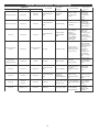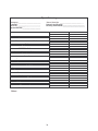
1
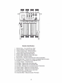
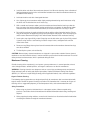
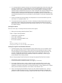
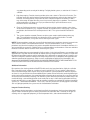
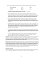
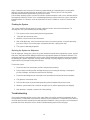
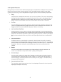
1"
6
1"
7
33%-50%
33%-50%
Waste Connection
Minimum Feed (gpm)
Recovery*
1"
10
33%-50%
* Recovery ratio may vary between 33% - 50% and up to 75% if system projections have been provided.
Feed Water & Operation Specifications
Nothing has a greater effect on a reverse osmosis system than the feed water quality. NOTE: It is very
important to meet the minimum feed water requirements. Failure to do so will cause the membranes to
foul and void the warranty.
Feed Water Specifications
Free Chlorine
Total Dissolved Solids
Turbidity (SDI)
<0 ppm
<2000 ppm
<5
Manganese
Organics
Silica
<0.05 ppm
<1 ppm
<1 ppm
pH
3-11
Iron
<2 ppm in Concentrate
Temperature
40°F-105°F
Hardness
<l5gpg
The manufacturer has provided you with the suggested operation specifications. These specifications
should be met in order to have the reverse osmosis system perform optimally. All operation specifications
are based on the test conditions listed below.
Operating Specifications
Minimum Feed Pressure
Nominal % Rejection
Maximum TDS
pH Range
35 psi
98.5%
2000 ppm
3-11
Minimum NaCI Rejection
Maximum Hardness
Operating Pressure
Maximum Temperature
96%
I5gpg
150 psi
105°F
Test Conditions: Permeate flow and salt rejection based on 550 ppm , 150 psi, 77°F (25°C), pH 7, and 50%
recovery as indicated. NOTE: Higher TDS and/or lower temperatures will reduce the system's production.
Rejection, Recovery, & Flow Rates
Thunder reverse osmosis systems are designed to produce purified water at the capacities indicated by the
suffix in the system's name under the conditions listed above. For example, the Thunder 7000 produces
7000 gallons per day of purified water @ 77°F.
The amount of total dissolved solids (TDS) rejected by the membrane is expressed as a percentage. For
example, a 99% rejection rate means that 99% of total dissolved solids do not pass through the membrane.
To calculate the % rejection, use the following formula:
% Rejection = [(Feed TDS - Product TDS) / Feed TDS] x 100
NOTE: All TDS figures must be expressed in the same units, usually parts per million (ppm) or milligrams per
liter (mg/l).
Thunder commercial reverse osmosis systems are designed to reject up to 98.5% NaCI, unless computer
projections have been provided and state a different rejection percentage.
The amount of purified water recovered for use is expressed as a percentage. To calculate % recovery,
use the following formula:
3
NOTE: Some permeate will be produced during the auto flush; therefore, an overflow for the permeate
storage tank is recommended.
Pump Bypass Valve
The pump bypass valve is installed as a standard feature on the Thunder 4000, 5000, & 7000 reverse
osmosis systems. It provides an adjustment for pump pressure, which will vary as the required system
pressure changes. Note that with a multi-stage pump, the pump flow decreases as the operating pressure
increases.
As the feed water temperature decreases, and/or the feed water TDS increases, the system will require a
higher operating pressure to produce the specified permeate flow. A Thunder system installed in Florida
may provide the specified permeate flow of 3.47 gpm at 150 psi; however the same system installed in
Maine - much colder feed water - may require 190 psi to produce the same amount of permeate. The
system in Florida would have a higher concentrate flow to the drain because of the lower operating
pressure, which would result in poor system recovery.
% Rejection = (Feed TDS - Product TDS)/(Feed TDS) x 100
Membrane Removal & Replacement
Changing membranes in pressure vessels is an easy process if you have the proper information and tools at
hand. Please refer to the following instructions when removing and replacing membrane elements:
1. Remove the end caps from the top of the membrane housings. This is done by removing the
white Nylon snap ring of the Champ housing or unscrewing the bolts of the housing,
which holds on the clamp.
2. Remove the membrane bag containing the membrane element from the shipping box.
3. Cut the bag open as close as possible to the seal at the end of the bag, so the bag may be re
used if necessary.
4. Remove the membrane element from the bag and remove the black core tube protectors from
each end of the membrane.
5. Remove parts from the parts container (if included) and inspect. Make sure that all parts are
clean and free from dirt. Examine the brine seal, and permeate tube for nicks or cuts. Replace the
0-rings or brine seal if damaged.
6. Flow directions should be observed for installation of each element in each housing.
As time progresses, the efficiency of the membrane will be reduced. In general, the salt rejection does not
change significantly until two or three years after installation when operated on properly pretreated feed
water. The permeate flow rate will begin to decline slightly after one year of operation, but can be extended
with diligent flushing and cleaning of the system. A high pH and/or precipitation of hardness can cause
premature loss in rejection of membrane elements in the system.
To replace the membrane elements:
1. Remove all of the membrane element(s) from the membrane element housings from the top of the
housing. Heavy-duty pliers and channel lock pliers may be necessary to pull the old membrane
element out of the membrane element housing.
10
2. Install the brine seal side of the membrane elements first. When the housings have a direction of
flow from bottom to top, the brine seal should be located on the end of the membrane element at
the bottom of the housing.
3. Lubricate the brine seal with a food grade lubricant.
4. At a slight angle insert membrane while slightly rotating element being careful not to tear or flip
the brine seal. Re-lube the brine seal if necessary.
5. With a smooth and constant motion, push the membrane element into the housing so that the
brine seal enters the housing without coming out of the brine seal groove. A slow twisting motion
should be used to insert the membrane element, to ensure that the brine seal stays in place.
6. Re-install the end caps by gently twisting the end cap while pushing it onto the housing. Ensure
that you do not pinch or fatigue any 0-rings while pushing the end plug on. Push the end plug on
until the outer diameter of the plug is flush with the outer diameter of the membrane housing.
7. Insert nylon snap ring until fully seated. Snap ring must be able to be spun in place if fully seated.
If you are using stainless steel housing, Install the clamps halves, and tighten bolts until the
clamp halves meet.
8. Reconnect any fittings that may have been disconnected when the membrane element housings
were disassembled.
9. To Start-Up the system, refer to Start-Up
CAUTION: New or factory cleaned membranes are shipped in a preservative solution. New or cleaned
membranes must be flushed for at least 1 hour to remove the preservative from the membrane. Discard all
of the permeate and concentrate, which is produced during the flush.
Membrane Cleaning
Periodic cleaning of the membrane(s) can improve system performance. In normal operation, mineral
scale, biological matter, colloidal particles, and organic substances can foul the membranes.
WARNING: Cleaning chemicals are dangerous and can cause injury and damage to the environment.
Read and comply with all safety and disposal precautions listed on the Material Safety Data Sheets
(MSDS's). It is the user's responsibility to comply with all applicable federal, state, and local regulations.
Organic Foulant Cleaning
The following cleaning procedures are designed specifically for membranes that have been fouled with
organic matter. Review the general cleaning instructions for information that is common to all types of
cleaning such as suggested equipment, pH and temperature limits, and recommended flow rates.
Safety Precautions
1. When using any chemical indicated here in subsequent sections, follow accepted safety
practices. Consult the chemical manufacturer for detailed information about safety, handling and
disposal.
2. When preparing cleaning solutions, ensure that all chemicals are dissolved and well mixed before
circulating the solutions through the membrane elements.
11
3. It is recommended the membrane elements be flushed with good-quality chlorine-free water after
cleaning. Permeate water is recommended; but a de-chlorinated potable supply or pre-filtered
feed water may be used, provided that there are no corrosion problems in the piping system.
Operate initially at reduced flow and pressure, to flush the bulk of the cleaning solution from the
elements before resuming normal operating pressures and flows. Despite this precaution,
cleaning chemicals will be present on the permeate side following cleaning. Therefore, permeate
must be diverted to drain for at least 10 minutes or until the water is clear when starting up after
cleaning.
4. During recirculation of cleaning solutions, the temperatures must not exceed 50°C at pH 2-10,
35°C at pH 1 -11, and 30°C at pH 1 -12.
5. For membrane elements greater than six inches in diameter, the flow direction during cleaning
must be the same as during normal operation to prevent element telescoping, because the
housing thrust ring is installed only on the reject end of the housing. This is also recommended
for smaller elements.
Cleaning Procedures
There are seven steps in cleaning membrane elements with organics.
1.
Make up the cleaning solution listed from Table 1.
Table 1: Organic Cleaning Solution
• Preferred 0.1% (wt) Soda Ash
• PH 12, 30°C maximum
• Preferred 0.1% (wt) NaOH 0.025% (wt)
« PH 12, 30°C maximum
Notes:
(wt) Denotes weight percent of active ingredient.
Cleaning chemical symbols in order used: NaOH is sodium hydroxide.
Cleaning the Organics from Membrane Elements
2. Low-flow pumping. Pump mixed, preheated cleaning solution to the vessel at conditions of low
flow rate (about half of that shown in Table 2) and low pressure to displace the process water.
Use only enough pressure to compensate for the pressure drop from feed to concentrate. The
pressure should be low enough that essentially no permeate is produced. A low pressure
minimizes re-deposition of dirt on the membrane. Dump the concentrate, as necessary, to
prevent dilution of the cleaning solution.
Table 2: Recommended Feed Flow Rate Per Housing During High Flow Rate Re-Circulation
•
«
Dependent on number of elements in pressure vessel.
4-Inch full-fit elements should be cleaned at 12-14 gpm (2.7-3.2 m3/hr).
3. Re-circulate. After the process water is displaced, cleaning solution will be present in the
concentrate stream that can be recycled to the cleaning solution tank. Recycle the cleaning
solution for 15 minutes or until there is no visible color change. If a color change occurs, dispose
of the cleaning solution and prepare a new solution as described in step 2.
4. Soak. Turn the pump off and allow the elements to soak. Soak the elements for 1 -15 hours
(soaking overnight will give best results). To maintain temperature during an extended soak
period, use a slow recirculation rate (about 10 percent of that shown in Table 2). Soak time will
12
vary depending on the severity of the fouling. For lightly fouled systems, a soak time of 1-2 hours is
sufficient.
5. High-flow pumping. Feed the cleaning solution at the rates shown in Table 2 for 45 minutes. The
high flow rate flushes out the foulants removed from the membrane surface by the cleaning. If the
elements are heavily fouled, using a flow rate that is 50 percent higher than shown in Table 2
may aid cleaning. At higher flow rates, excessive pressure drop may be a problem. The maximum
recommended pressure drops are 15 psi per element or 50 psi per multi-element vessel,
whichever value is more limiting.
6. Flush out. Prefiltered raw water can be used for flushing out the cleaning solution, unless there
will be corrosion problems (e.g., stagnant seawater will corrode stainless steel piping). To prevent
precipitation, the minimum flush out temperature is 20°C. The system should be flushed for 1
hour.
7. The system should be restarted. Elements and the system need to stabilize before taking any
data. The stabilization period will vary depending on the severity of the fouling. To regain
optimum performance, it may take several cleaning and soak cycles.
NOTE: Recommendations made here are specifically designed for the membrane elements inserted in the
Titan™ reverse osmosis and nanofiltration elements. These recommendations, such as cleaning
procedures and chemicals employed, may not be compatible with other brands of membrane elements. It is
your responsibility to ensure the suitability of these recommendations and procedures if they are applied to
membrane elements other than those which come with your system.
NOTE: No freedom from any patent owned by Seller or others is to be inferred. Because use conditions and
applicable laws may differ from one location to another and may change with time, Customer is responsible
for determining whether products and the information in this document are appropriate for Customer's use
and for ensuring that Customer's workplace and disposal practices are in compliance with applicable laws
and other governmental enactments. Seller assumes no obligation or liability for the information in this
document. NO WARRANTIES ARE GIVEN; ALL IMPLIED WARRANTIES OF MERCHANTABILITY OR
FITNESS FOR A PARTICULAR PURPOSE ARE EXPRESSLY EXCLUDED.
Additional Information
By experience, the cleaning solution of Na4EDTA with caustic has been found to be slightly less effective
than a standard caustic solution or a solution of caustic and Na-DSS. For any solution, contact time is
critical. Several overnight soaks may be necessary to restore the system performance. After the elements
are clean it is very beneficial to clean one additional time in order to clean off the last remaining biofilm layer
on the surface of the membrane. Any remaining biofilm will tend to attract and trap dirt, so an extra cleaning
will increase the time between cleanings. For industrial systems where the permeate or product water is not
used for drinking, a non-oxidizing biocide can be used prior to step 1 of the cleaning procedure to kill any
bacteria or biofilm in the system. Please refer to separate instructions on methods for sanitizing membrane
systems (i.e., "Sanitization with DBNPA - Tech Facts"). If the only choice for a sanitizing agent is an oxidant,
such as hydrogen peroxide, the system must be cleaned before sanitization.
Inorganic Foulant Cleaning
The following cleaning procedures are designed specifically for membranes that have been fouled with
organic matter. Review the general cleaning instructions for information that is common to all types of
cleaning such as suggested equipment, pH and temperature limits, and recommended flow rates.
13
Safety Precautions
1. When using any chemical indicated here in subsequent sections, follow accepted safety
practices. Consult the chemical manufacturer for detailed information about safety, handling and
disposal.
2. When preparing cleaning solutions, ensure that all chemicals are dissolved and well mixed before
circulating the solutions through the membrane elements.
3. It is recommended the membrane elements be flushed with good-quality chlorine-free water after
cleaning. Permeate water is recommended; but a de-chlorinated potable supply or pre-filtered
feed water may be used, provided that there are no corrosion problems in the piping system.
Operate initially at reduced flow and pressure, to flush the bulk of the cleaning solution from the
elements before resuming normal operating pressures and flows. Despite this precaution,
cleaning chemicals will be present on the permeate side following cleaning. Therefore, permeate
must be diverted to drain for at least 10 minutes or until the water is clear when starting up after
cleaning.
4. During recirculation of cleaning solutions, the temperatures must not exceed 50°C at pH 2-10,
35°C at pH 1-1 1 , and 30°C at pH 1-12.
5. For membrane elements greater than six inches in diameter, the flow direction during cleaning
must be the same as during normal operation to prevent element telescoping, because the
housing thrust ring is installed only on the reject end of the housing. This is also recommended
for smaller elements.
Cleaning Procedures
There are seven steps in cleaning membrane elements with Inorganics. 1 .
Make up the cleaning solution listed from Table 1 . Table 1: Inorganic
Cleaning Solution
•
•
Preferred 2.0% (wt) Citric Acid PH 2, 45°C maximum
Alternate Muriatic Acid
Notes:
(wt) denotes weight percent of active ingredient.
Cleaning chemical symbols in order used: HCI is hydrochloric acid (Muriatic Acid).
Cleaning the Inorganics from Membrane Elements
•
•
Alternative 1.0%
Alternative 0.5% HsPCU
Notes:
1 (wt) denotes weight percent of active ingredient.
2 Cleaning chemical symbols in order used: HCI is hydrochloric acid (Muriatic Acid).
2. Low-flow pumping. Pump mixed, preheated cleaning solution to the vessel at conditions of low
flow rate (about half of that shown in Table 2) and low pressure to displace the process water. Use
only enough pressure to compensate for the pressure drop from feed to concentrate. The pressure
should be low enough that essentially no permeate is produced (approx. 60 psi). A low pressure
minimizes redeposition of dirt on the membrane. Dump the concentrate, as necessary, to prevent
dilution of the cleaning solution.
14
Table 2: Recommended Feed Flow Rate Per Housing During High Flow Rate Re-Circulation
Element Diameter
2.5 Inches
4 Inches
•
•
PSI
20 - 60
20-60
GPM
3-5
8-1 0
Dependent on number of elements in pressure vessel.
4-Inch full-fit elements should be cleaned at 12-14 gpm (2.7-3.2 m3/hr).
3. Re-circulate. After the process water is displaced, cleaning solution will be present in the
concentrate stream that can be recycled to the cleaning solution tank. Recycle the cleaning
solution for 10 minutes or until there is no visible color change. If at anytime during the circulation
process there is a change in pH or a color change, dispose of the solution and prepare a new
solution as described in step 2. A pH of 2 must be maintained for the cleaning to be effective.
4. Soak. Turn the pump off and allow the elements to soak. Soak the elements for 1-15 hours
(soaking overnight will give best results). To maintain temperature during an extended soak
period, use a slow recirculation rate (about 10 percent of that shown in Table 2). Soak time will
vary depending on the severity of the scaling. For lightly scaled systems, a soak time of 1-2 hours
is sufficient.
5. High-flow pumping. Feed the cleaning solution at the rates shown in Table 2 for 10 minutes. The
high flow rate flushes out the foulants removed from the membrane surface by the cleaning. If the
elements are heavily fouled, using a flow rate that is 50 percent higher than shown in Table 2
may aid cleaning. At higher flow rates, excessive pressure drop may be a problem. The maximum
recommended pressure drops are 15 psi per element or 50 psi per multi-element vessel,
whichever value is more limiting.
6. Flush out. Prefiltered raw water can be used for flushing out the cleaning solution, unless there
will be corrosion problems (e.g., stagnant seawater will corrode stainless steel piping). To prevent
precipitation, the minimum flush out temperature is 20°C. The system should be flushed for one
hour.
7. The system should be restarted. Elements and the system need to stabilize before taking any
data. The stabilization period will vary depending on the severity of the fouling. To regain
optimum performance, it may take several cleaning and soak cycles.
NOTE: Recommendations made here are specifically designed for the membrane elements inserted in the
Thunder reverse osmosis and nanofiltration elements. These recommendations, such as cleaning
procedures and chemicals employed, may not be compatible with other brands of membrane elements. It is
your responsibility to ensure the suitability of these recommendations and procedures if they are applied to
membrane elements other than those which come with your system.
NOTE: No freedom from any patent owned by Seller or others is to be inferred. Because use conditions and
applicable laws may differ from one location to another and may change with time, Customer is responsible
for determining whether products and the information in this document are appropriate for Customer's use
and for ensuring that Customer's workplace and disposal practices are in compliance with applicable laws
and other governmental enactments. Seller assumes no obligation or liability for the information in this
document. NO WARRANTIES ARE GIVEN; ALL IMPLIED WARRANTIES OF MERCHANTABILITY OR
FITNESS FOR A PARTICULAR PURPOSE ARE EXPRESSLY EXCLUDED.
Additional Information
Never recirculate the cleaning solution for longer than 20 minutes. With longer recirculation, the carbonate
scale can reprecipitate and end up back on the membrane surface, making it more difficult to
15
clean. Carbonate scale reacts with HCI releasing carbon dioxide gas. Depending on the severity of the
fouling, it may take repeated cleanings to remove all the scale. Cleaning severe scale may not be
economical and element replacement may be the best choice.
Citric acid was originally used as a cleaner for cellulose acetate membranes and is not as effective with thin
film composite chemistry. Further, it has a disadvantage of being a nutrient source for systems, which have
biological fouling. It is, however, easier to handle than HCI and is included as a primary cleaner for that
reason.
Flushing the System
The system should be flushed weekly to remove sediment from the surface of the membranes. To
manually flush the system following the preceding steps:
1. The system must be running during the flushing procedure.
2. Fully open the concentrate valve
3. Allow the system to run for 10 to 20 minutes.
4. After 10 to 20 minutes, close the concentrate valve to its previous position, raising the operating
pressure to 150 psi. Ensure the proper concentrate flow rate is going to the drain.
5. The system is now ready to operate.
Draining the System for Shipment
Prior to shipping or storing your system, the system should be cleaned with an appropriate cleaner, flushed
with water, and protected from biological attack with an appropriate solution for membrane elements. The
membrane housing(s) and plumbing lines of the system must be completely drained. Any water remaining in
the plumbing of a system may freeze, causing serious damage. The party shipping or storing the system is
responsible for any damage resulting from freezing.
To drain the system:
1. Disconnect the inlet, concentrate, pre-filter, and permeate plumbing.
2. Drain all water from the pre-filter cartridge housings by unscrewing the housings, removing the
pre-filter cartridges, and drain the water from the housings.
3. Disconnect the tubing from the connector on the permeate and concentrate inlets and outlets.
4. Fully open the concentrate valve.
5. Drain the flow meters by disconnecting the tubing from the bottom fitting of each meter.
6. Allow the system to drain for a minimum of eight hours or until the opened ports quit dripping.
7. After draining is complete, reconnect all of the plumbing.
Troubleshooting
If the system production declines or the system stops working, check the mechanical components for any
visual problems. Listed below are the items to check for any visual problems. Listed below are the items to
check for two of the most commonly encountered problem conditions: Low system pressure and abnormal
permeate flow. Also refer to the reverse osmosis troubleshooting matrix on the next page.
16
Low System Pressure
Low system pressure occurs when sufficient feed water pressure and flow are not obtained. This causes the
high-pressure reverse osmosis pump to cavitate. Failure to provide the proper feed will result in lower
system pressure that may result in low production and poor rejection. Check the following components:
1.
Pump:
Isolate the pump and determine how much pressure can be achieved. This can be determined by
checking the pump discharge pressure gauge at this point. If the system is not equipped with this
gauge, disconnect the hose that runs from the pump to the pressure vessel. Install a pressure
gauge. The pressure of the pump must reach at least 190 psi when the flow is restricted.
2. Pre-Filter:
Check the differential in the pre-filter gauges to determine if the filter needs to be replaced. If the
system is not equipped with these gauges, examine the pre-filter cartridge to make sure that it is not
clogged and does not restrict feed flow to the pump. Replace, if necessary.
3. Low Feed Water Flow Rate:
Determine that the system is getting a sufficient volume of feed water. Disconnect the feed water
hose from the system and place it in a one gallon bucket. Measure the time it takes to fill the bucket
to determine the feed flow. (Feed flow is measured in gallons per minute, so divide 1 gallon by the
time in minutes to obtain the flow rate). Refer to the System Specifications for the required feed
flow.
4. Inlet Solenoid Valve:
Feed water enters the system through an automatic solenoid shut-off valve, which is normally
closed. Ensure that the solenoid opens when the reverse osmosis pump starts. The system can be
operated without the solenoid for troubleshooting. Remove the solenoid to see if it is contributing to
the problem. Normally, cleaning the solenoid diaphragm will correct any malfunction of the
solenoid.
5.
Electric:
Check to ensure that there are no electrical fuses blown and that all electrical connections are
secure. Use a voltmeter to verify that the motor is getting sufficient power.
6. Pressure Gauge:
Check for foreign matter on the gauge fitting. Remove any visible matter and replace the fitting.
Verify that the tube is not pushed too far inside the fitting. This could restrict flow and cause an
inaccurate display. If the fitting and tube are fine and the pressure gauge is still malfunctioning,
the gauge should be replaced.
7. Concentrate Control Valve:
The concentrate control valve may have a tear in the diaphragm. Remove the valve, inspect the
diaphragm, and replace if necessary.
17
Pump
The pumps used on Thunder 4000, 5000, & 7000 systems are pump and motor combinations. They are
multi-stage centrifugal pumps. Follow these guidelines to ensure proper operation of the pump:
•
The pump must NEVER be run dry. Operating the pump without sufficient feed water will damage
the pump.
•
ALWAYS feed the pump with filtered water. The pump is susceptible to damage from sediment
and debris.
•
If any damage occurs to your system's pump a re-build kit may be available. Contact your local
dealer or distributor and inform them of your system's model and pump size.
Mounting
The free standing system should be bolted down in compliance with local regulation standards or
securely fastened.
Membrane Elements
Thunder reverse osmosis systems come pre-loaded with Thin Film Composite (TFC) High Flow Low
Energy membranes, unless otherwise specified. General membrane element performance characteristics
are listed below:
Membrane Element Characteristics
Operating Pressure
Nominal % Rejection
Maximum Temperature:
Silt Density Index
150psi
98.5%
110°F
<5 SDI
Maximum Pressure
Chlorine Tolerance
Turbidity
pH Range
400 psi
<1 ppm
1 NTU
3-11
Test Conditions: Permeate flow and salt rejection based on 550 ppm, 150 psi, 77°F (25°C), pH 7, and 15%
recovery. NOTE: Higher TDS and/or lower temperatures will reduce the membrane's production.
Start-Up
Unless otherwise indicated, these instructions cover the Thunder 4000, 5000, & 7000 reverse osmosis
systems. Please refer to the flow diagrams and exploded view diagrams found in this User's Manual for
additional information and reference.
Installation
Thunder reverse osmosis systems must be securely mounted and placed on an even floor, so that the
system will not vibrate or move. If this occurs, place the system on a rubber mat to reduce the vibrations and
movement.
Carefully inspect your system before start-up. Check that all plumbing and electrical connections are not
loose or have not come undone during shipment. A User's Manual, Test Results, and Filter Housing
Wrench will accompany your Thunder reverse osmosis system
5
System Purging:
NOTE: Leave the power to the system off for this procedure.
1.
2.
3.
4.
5.
6.
Redirect permeate water to the drain for this procedure.
Fully open the concentrate valve #9 (Counter Clockwise).
Fully close the recycle valve # 8 (Clockwise)(lf Applicable).
Fully close the bypass valve mounted on the RO pump.
Offset the position of the bypass white lever on the solenoid valve #1.
Turn the feed water on and let the system purge until no visible bubbles appear from concentrate flow
meter #13.
7. See page 6 for Number Identification. Use this procedure when starting up a new system or when
membranes are being replaced.
Initial Start-Up (After Purging):
1.
2.
3.
4.
5.
Fully open concentrate valve #9 (Counter Clockwise)
Fully close recycle valve # 8 (Clockwise)(lf Applicable)
Fully open bypass valve mounted on RO pump.
Return position of bypass white lever on the solenoid valve #1.
Turn RO system on #7 and adjust bypass valve, concentrate (waste) valve #8 and recycle valve # 9(lf
Applicable) to designed flow and pressure.
6. Inspect for leaks and after one hour shut down system. Re-direct permeate back to tank or POU and
then turn sytem back on.
7. Record readings daily for a week and after a week record readings once a week.
8. See Page 6 for Number Identification. See below for detailed startup procedures.
Start-Up
1. Locate the 1" FNPT Solenoid Valve feed water inlet next to the filter housing.
2. Attach the inlet piping to the 1" FNPT Solenoid Valve feed water inlet. Always maintain a smooth
and sufficient flow of feed water during operation.
3. Locate the 1" FNPT permeate outlet.
4. Attach the permeate piping to the permeate outlet. Make sure that the permeate water can flow
freely and that there is no backpressure. Backpressure can cause damage to the membrane
elements.
CAUTION: The plumbing in the permeate line can contaminate the high quality water produced by
the system; ensure that the components are compatible with the application. The pH of the reverse
osmosis permeate water will normally be 1-2 points lower than the feed water pH. A low pH can be
very aggressive to some plumbing materials such as copper piping.
5. Locate the concentrate outlet on the drain side of the concentrate control valve.
6. Attach the drain line to the concentrate outlet. Water must be allowed to run freely, without any
restrictions or blockage in the drain line. Make sure that no backpressure exists on the
concentrate line.
7
7. Ensure that the electrical power requirements of the Thunder system match your electrical power
supply.
8. Thunder systems are typically controlled with a liquid level switch in a storage tank. The liquid
level switch turns the system on when the water level in the tank drops, and off when the tank is
full. If your reverse osmosis system is equipped with an electrical control box, the level control is
connected to the level control connections in the control box. The level control connections are
dry contacts and never apply power to these connections. Liquid level switches can be obtained
by your local dealer or distributor. If a liquid level switch is to be used, install it at this time.
9. Disconnect the permeate line to the storage tank or point-of-use application and direct it to the
drain. Flush the system for approximately 15 minutes with the feed water by fully opening the
concentrate valve counter-clockwise. This will assist in removing any impurities or preservative
within the system. At this time check for any wetted parts which may have been damaged during
shipment. After 15 minutes shut down the feed water.
10. Turn on the power to the system.
11. Follow any specified system projections supplied.
12. Make sure that no backpressure exists on the permeate line.
13. Locate the concentrate control valve and the concentrate pressure gauge.
14. Turn the concentrate control valve until the designated recovery is acquired. The concentrate
pressure will increase as the concentrate control valve is closed. The exact operating pressure
may vary depending on the temperature and TDS of your feed water. It may be necessary to re
adjust the system if there is a major change in feed water temperature and/or TDS.
15. Turn the pump bypass valve until the correct pump pressure is achieved. For example a Thunder
5000 should be adjusted until it produces about 5000 GPD or 3.47 GPM of permeate or product
water at 77°F.
GPM = GPD/1440
WARNING: Never exceed the maximum pressure rating of your pressure vessels.
Operation & Maintenance
The reverse osmosis process causes the concentration of impurities. The impurities may precipitate (come
out of solution) when their concentration reaches saturation levels. NOTE: Precipitation can scale or foul
membranes and must be prevented.
Check your feed water chemistry and pre-treat the water and/or reduce the system's recovery as
required. If necessary, consult with your local dealer or distributor.
Pre-Filter Pressure Gauges
These gauges measure the feed water pressure when it enters and exits the pre-filter housings. A
pressure differential of 10 -15 psi or more on the two pressure gauges indicates that the pre-filters require
servicing. For example, if the inlet pressure is 40 psi, the filter should be changed when the outlet pressure is
30 psi or below.
8
Product (Permeate) Flow Meter & Waste (Concentrate) Flow Meter
These flow meters indicate the flow rates of the permeate and concentrate water. The measurements, when
added together, also indicate the feed water flow rate or (total flow rate); if the system is not equipped with
a concentrate recycle valve.
Waste (Concentrate) Recycle Valve
This valve allows you to recycle some of the concentrate water back into the feed of the pump. This will
increase the recovery of the Thunder system. An optional waste recycle flow meter allows you to measure
how much concentrate is recycled. The amount of waste water recycled is limited by the TDS of the feed
water. The drawback of using a concentrate recycle is that there will be an increase of total dissolved solids
in the permeate water.
CAUTION: Excessive recycling may cause premature fouling or scaling of the membrane elements.
RO Controller
The RO Controller is located on the front panel of your Thunder system. There is a low pressure shut-off
switch which monitors the system's feed water pressure and that will shut off the system and sound alarm if
pressure loss is detected. It will also shut down the system when the tank is full using the liquid level switch.
Auto Flush
The auto flush option bypasses the concentrate control valve, reducing the concentrate pressure and
increasing the flow of feed water across the membrane. The auto flush removes foulants that may have
attached to the surface of the membrane. By removing these foulants before they crystallize on the surface
of the membrane, the system can operate longer without cleaning and/or replacing the membrane elements.
The following are instances in which the auto-flush should be utilized:
1. When injecting antiscalant chemicals. These chemicals keep scaling ions in solution up to a
higher concentration so the ions don't precipitate, and scale the membrane elements. If the
solubility concentration is exceeded, the ions may precipitate and scale the membrane.
2. For feed water with a high scaling potential (hard water) in addition to the auto flush, pre-treat the
water with an anti scalant or a water softener.
3. Where minimal maintenance is important, auto flush can increase the time between membrane
cleanings.
4. For high TDS (total dissolved solids) applications where the TDS exceeds 550 ppm.
5. For higher recovery applications (that use a recycle valve).
6. For systems that may remain inoperative for long periods of time, auto-flush should be installed.
The auto-flush will not operate if the electrical power is removed from the system.
The auto flush feature includes an adjustable setting that regulates its operation. In the auto flush mode the
water will flush across the membrane in the same direction as the water flows in normal operation; this is not
a backwash flow.
9
8. Motor:
The motor may not be drawing the correct current. Use a clamp-on amp meter to check the
current draw.
9. Leaks:
Check the system for leaks, as this can result in low pressure.
Abnormal Permeate Flow
Permeate flow should be within 15% of the rated production, after correcting the feed water temperatures
above or below 77°F. Check your permeate flow meter to determine the permeate flow rate. If the system
does not have a permeate flow meter, measure the time it takes to fill a 1 gallon container then calculate the
permeate flow rate at gallons per minute or gallons per day.
NOTE: To determine the temperature correction factor, locate the Temperature Correction Table in this
User's Manual and follow the directions.
1. Causes of Low Permeate Flow:
•
•
•
•
Cold Feed Water
Low Operating Pressure
Defective Membrane Brine Seal
Fouled or Scaled Membrane
2. Causes of High Permeate Flow:
•
Defective Product Tube O-Rings
•
Defective or Oxidized Membrane
3. Causes of Poor Permeate Quality:
•
•
•
Low Operating Pressure
Defective Product Tube O-Rings
Defective or Oxidized Membrane
18
|
Reverse Osmosis System Troubleshooting
Salt Passage
Symptoms
Permeate Flow
Normal to Increased
Decreased
Normal to Increased
Increased
Normal to Moderate
Increase
Decreased or
Slightly Increased
Decreased
Decreased
Decreased
Decreased
Pressure Drop
Normal to
Increased
Increased
Increased
Normal to Moderate
Increase
Normal
Location
Predominately First
Stage
Predominately First
Stage
Predominately First
Stage
Any Stage
Any Stage
Possible
Causes
Metal Oxide
Fouling
Verification
Analysis of Metal
Ions in Cleaning
Solution.
Corrective
Action
Improve
pretreatment to
remove metals.
Clean with Acid
Cleaners.
Optimize
pretreatment for
colloid removal.
Clean with high pH
anionic cleaners.
Colloidal Fouling
SDI Measurement of
Feed Water.
Scaling (CaS04,
CaSOS, BaSO4,
SiO2)
Analysis of metal
ions in cleaning
solution by
checking LSI of
reject. Calculate
max. solubility of
CaSO4, BaS04,
SiO2 in reject.
Increase acid
addition and
antiscalant dosage
for CaVOS and
CaCO4. Reduce
recovery. Clean with
Acid Cleaners.
Bacteria count in
permeate and reject.
Slime in pipes and
pressure vessels.
Shock dosage of
Sodium Bi-Sulfate.
Continuous feed of
Sodium Bi-Sulfate at
reduced pH.
Formaldehyde
disinfection.
Chlorination and
de-chlorination.
Replace cartridge
filters.
Biological Fouling
Organic Fouling
Destructive
Element Testing.
Chlorine Oxidation
Chlorine Analysis of
feed water.
Destructive element
test.
Microscopic solids
analysis of feed.
Destructive element
test.
Activated Carbon or
other pretreatment.
Clean with high pH
cleaner.
Check Chlorine feed
equipment and
de-chlorination
system.
Increased
Increased
Decreased
Most Severe in First
Stage
Increased
Increased
Decreased
Most Severe in First
Stage
Abrasion of
membrane by
Crystalline Material
Increased
Normal to
Increased
Decreased
At Random
Probe test. Vacuum
Replace 0-Rings.
O-Ring Leaks, End or
test. Colloidal material Repair or replace
Side Seal Leaks
test.
elements.
Increased
Normal to Low
Decreased
At Random
Recovery Too High
19
Check Flows and
Pressure Against
Design Guidelines.
Improve
pretreatment. Check
all filters for media
leakage.
Reduce the
recovery rate.
Calibrate and/or
add sensors.
Operation Log
Company:__________________________
Location: ____________________________
Week Of:____________________________
System Serial #:_____________________
Date of Start-Up: ____________________________
Date of Last Cleaning:_________________________
Cleaning Formulation:_________________________
Date
Time
Hours of Operation
Cartridge Filter Inlet Pressure (psi)
Differential Pressure (psi)
Permeate Pressure (psi)
Feed Pressure (psi)
Concentrate Pressure (psi)
Differential Pressure (psi)
Pump Discharge Pressure (psi)
Permeate Flow (GPM)
Concentrate Flow (GPM)
Feed Flow (GPM)
Recovery %
Feed Temperature
Feed Conductivity (mg/L)
Permeate Conductivity (mg/L)
Rejection %
FeedpH
Permeate pH
Scale Inhibitor Feed (ppm)
Acid Feed (ppm)
Sodium Bisulfite Feed (ppm)
Feed Water:
Iron (mg/L)
Free Chlorine (mg/L)
Hardness (ppm CaCOS)
Turbidity (NTU)
Notes:
20
Temperature Correction Factors For Membrane Flux
TEMPERATURE
•c
•F
CA
TF
10°
50°
1.468
(Thin Film Composite}
1.71!
11°
52°
1.429
1.648
12°
54°
1.391
1.588
13°
55°
1.355
1.530
14°
57°
1.320
1.475
15°
59°
1.286
1.422
16°
61°
1.253
1.371
17°
63°
1,221
1.323
18°
64°
1.190
1.276
19°
66°
1.160
1.232
20°
68°
1.132
1.189
21°
70°
L1O4
1.148
22°
72°
1.O76
1.109
23°
73°
1.050
1.071
24°
75°
1.025
1.O35
25°
77°
(Cellulose Acetate)
1.000
1.000
26°
79°
0.988
0.971
27°
81°
0.976
0.943
28°
82°
O.964
0.915
29°
84°
O.953
0.889
30°
86°
0.942
O.863
To use: Simply multiply the actual flux to obtain temperature corrected flax.
21
Service Assistance
If service assistance is required, take the following steps:
1. Call your distributor.
a. Prior to making the call, have the following information available:
i. Machine installation date
ii. Serial number (found on left-hand side of front panel)
iii. Daily Log Sheets
iv. Current operating parameters (i.e., flow, operating pressures, pH, etc.)
v. Detailed description of problem
Warranty & Guarantee
Reverse Osmosis System One-Year Limited Warranty
Warranty Terms
Subject to the terms and conditions set forth hereinafter, Seller warrants to the original purchaser
(hereafter the "Buyer") that the products manufactured by Seller are free from defects in material and in
workmanship for twelve (12) months from the Warranty Commencement Date (as defined below) only
when used strictly in accordance with the applicable operating instructions and within the range of the
operating conditions specified by Seller for each such product.
This Warranty does not extend to equipment or components manufactured by others into which a Seller
product has been incorporated or to equipment or components which have been incorporated into a
Seller product but, if allowable, Seller hereby assigns, without warranty, to the Buyer its interest, if any,
under any warranty made by the manufacturer of such equipment or component. This Warranty does not
cover disposable items such as fuses, lamps, filters, cartridges, or other such disposable items, which
must be replaced periodically under the normal and foreseeable operating conditions of the goods
warranted hereby.
Warranty Commencement Date
The Warranty Commencement Date for each Seller product shall be the later of the date of: (1) receipt by
the Buyer, or (2) the date of installation at the Buyer's premises provided that such installation must occur
within three (3) months of shipment from the Seller's manufacturing facility in California. In no event shall the
Warranty Commencement Date exceed three (3) months from the shipment from the Seller's
manufacturing facility. The Buyer shall provide proof of purchase in order to exercise rights granted under
this Warranty. If requested by manufacturer, the Buyer must also provide proof of the installation date.
Proof of installation shall be returned by Buyer to Seller within thirty (30) days after installation by virtue of
supplying a Warranty Validation Card supplied with each Seller product fully completed and signed in ink by
Buyer and the authorized installer of the product.
Warranty Service
SELLER'S OBLIGATION UNDER THIS WARRANTY IS LIMITED TO THE REPAIR OR REPLACEMENT
(AT SELLER'S SOLE DISCRETION) OF ANY PRODUCT, OR COMPONENT THEREOF, PROVED TO
BE DEFECTIVE IN MATERIAL OR WORKMANSHIP WITHIN THE COVERED WARRANTY PERIOD.
The buyer, at the Buyer's risk and expense, shall be responsible for returning such product or component,
only after obtaining a Return Goods Authorization (RGA) number from the Seller, arranging for freight
27
prepaid, and in conformance with any special packaging and shipping instructions set forth on the
operation documentation or RGA instructions, or as otherwise reasonably required, to the Seller's
address set forth below, together with (1) RGA number issued by Seller at Buyer's request; (2) proof of
purchase and, if necessary, proof of installation date; (3) a Return Good Authorization Form; (4) a
description of the suspected defects; (5) the serial number of the Seller product alleged to be defective;
and (6) a description of the type of water and pretreatment equipment which has been utilized in
connection with the product, if any. Seller shall, in Seller's reasonable discretion, be the sole judge of
whether a returned product or component is defective in material or workmanship. Required or replaced
products or components shall be returned surface freight. In genuine emergency situations, the Seller will
(at Seller's sole discretion) forward replacement parts to Buyer without waiting for authorized return of the
questionable part(s). In such cases, Buyer will issue a purchase order or other payment guarantee prior
to shipment. If the returned part is found to have been misused or abused, the defective part is not
received by Seller within thirty (30) days; the Buyer will be invoiced for the replacement part(s) provided.
This Warranty does not cover or include labor and/or travel to the Buyer's premise or location or any other
location. Charges of $1000 per day plus associated travel expenses will be incurred by the Buyer in
providing the Warranty Service at any location other than Seller's main headquarters; that is if the Seller
deems that the product is not covered by said Warranty. The Seller reserves the right to precondition
such travel to Buyer's premises upon prepayment of Seller's anticipated costs of attending such
premises.
Voidability of Warranty
This Warranty shall be void and unenforceable as to any Seller product which has been damaged by
accident, mishandling, abuse or has been repaired, modified, altered, disassembled or otherwise
tampered with by anyone other than Seller or an authorized Seller service representative; or, if any
replacement parts are not authorized by Seller have been used, or, the product has not been installed,
operated and maintained in strict accordance and adherence with the operating documentation and
manuals for such product. Any expressed warranty, or similar representation of performance set forth in
the operation documentation for a reverse osmosis, nanofiltration, or ultrafiltration membrane
incorporated into a Seller product shall be void and unenforceable unless the feed water requirements set
forth in the operating documentation for such product are unequivocally and strictly adhered to.
Limitations and Exclusions
THIS WARRANTY AND REMEDIES DESCRIBED HEREIN AND HEREINABOVE ARE EXCLUSIVE
AND IN LIEU OF ANY AND ALL OTHER WARRANTY OR REMEDIES, EXPRESSED OR IMPLIED,
INCLUDING WITHOUT LIMITATION, ANY IMPLIED WARRANTY OF MERCHANTABILITY OR
FITNESS FOR A PARTICULAR PURPOSE. IN NO EVENT SHALL THE SELLER BE LIABLE FOR ANY
CONSEQUENTIAL, INCIDENTAL OR OTHER SIMILAR TYPES OF DAMAGES, FOR DAMAGES FOR
THE LOSS OF PRODUCTION OR PROFITS, OR INJURY TO PERSON OR PROPERTY. NO PERSON
HAS ANY AUTHORITY TO BIND SELLER TO OTHER THAN WHAT IS SET FORTH ABOVE.
THIS WARRANTY GIVES THE BUYER SPECIFIC LEGAL RIGHTS AND THE BUYER MAY ALSO
HAVE OTHER RIGHTS WHICH VARY FROM JURISDICTION TO JURISDICTION. THE PARTIES
RECOGNIZE AND AGREE, THAT IN ALL RESPECTS THE LAWS OF THE STATE OF CALIFORNIA
SHALL APPLY TO AND SHALL GOVERN ANY INTERPRETATION OR LEGAL SIGNIFICANCE OF
THIS DOCUMENT.
NO WARRANTY OR OTHER LIABILITY OF SELLER TO BUYER UNDER THIS AGREEMENT OR
OTHERWISE WILL IN ANY EVENT EXCEED THE COST OF REPLACEMENT OF THE APPLICABLE
SELLER PRODUCT, PART, OR ACCESSORY THAT IS SUBJECT TO ANY BREACH OF SELLER'S
WARRANTY. SELLER WILL NOT BE LIABLE FOR ANY DAMAGE TO ANY PROPERTY OF BUYER OR
TO BUYER'S CUSTOMERS FOR ANY CONSEQUENTIAL, INCIDENTAL, OR ECONOMIC LOSS OR
COMMERCIAL DAMAGE WHATSOEVER. REMEDIES HEREIN PROVIDED ARE EXPRESSLY MADE
THE SOLE AND EXCLUSIVE REMEDIES FOR BREACH OF ANYWARRANTY OR OTHER
OBLIGATION HEREUNDER EXPRESS OR IMPLIED OR FROM THE OPERATION OF LAW.
28