1
To our customers,
Old Company Name in Catalogs and Other Documents
On April 1st, 2010, NEC Electronics Corporation merged with Renesas Technology
Corporation, and Renesas Electronics Corporation took over all the business of both
companies. Therefore, although the old company name remains in this document, it is a valid
Renesas Electronics document. We appreciate your understanding.
Renesas Electronics website: http://www.renesas.com
April 1st, 2010
Renesas Electronics Corporation
Issued by: Renesas Electronics Corporation (http://www.renesas.com)
Send any inquiries to http://www.renesas.com/inquiry.
Note that the following URLs in this document are not available:
http://www.necel.com/
http://www2.renesas.com/
Please refer to the following instead:
Development Tools | http://www.renesas.com/tools
Download | http://www.renesas.com/tool_download
For any inquiries or feedback, please contact your region.
http://www.renesas.com/inquiry
Notice
1.
2.
3.
4.
5.
6.
7.
All information included in this document is current as of the date this document is issued. Such information, however, is
subject to change without any prior notice. Before purchasing or using any Renesas Electronics products listed herein, please
confirm the latest product information with a Renesas Electronics sales office. Also, please pay regular and careful attention to
additional and different information to be disclosed by Renesas Electronics such as that disclosed through our website.
Renesas Electronics does not assume any liability for infringement of patents, copyrights, or other intellectual property rights
of third parties by or arising from the use of Renesas Electronics products or technical information described in this document.
No license, express, implied or otherwise, is granted hereby under any patents, copyrights or other intellectual property rights
of Renesas Electronics or others.
You should not alter, modify, copy, or otherwise misappropriate any Renesas Electronics product, whether in whole or in part.
Descriptions of circuits, software and other related information in this document are provided only to illustrate the operation of
semiconductor products and application examples. You are fully responsible for the incorporation of these circuits, software,
and information in the design of your equipment. Renesas Electronics assumes no responsibility for any losses incurred by
you or third parties arising from the use of these circuits, software, or information.
When exporting the products or technology described in this document, you should comply with the applicable export control
laws and regulations and follow the procedures required by such laws and regulations. You should not use Renesas
Electronics products or the technology described in this document for any purpose relating to military applications or use by
the military, including but not limited to the development of weapons of mass destruction. Renesas Electronics products and
technology may not be used for or incorporated into any products or systems whose manufacture, use, or sale is prohibited
under any applicable domestic or foreign laws or regulations.
Renesas Electronics has used reasonable care in preparing the information included in this document, but Renesas Electronics
does not warrant that such information is error free. Renesas Electronics assumes no liability whatsoever for any damages
incurred by you resulting from errors in or omissions from the information included herein.
Renesas Electronics products are classified according to the following three quality grades: “Standard”, “High Quality”, and
“Specific”. The recommended applications for each Renesas Electronics product depends on the product’s quality grade, as
indicated below. You must check the quality grade of each Renesas Electronics product before using it in a particular
application. You may not use any Renesas Electronics product for any application categorized as “Specific” without the prior
written consent of Renesas Electronics. Further, you may not use any Renesas Electronics product for any application for
which it is not intended without the prior written consent of Renesas Electronics. Renesas Electronics shall not be in any way
liable for any damages or losses incurred by you or third parties arising from the use of any Renesas Electronics product for an
application categorized as “Specific” or for which the product is not intended where you have failed to obtain the prior written
consent of Renesas Electronics. The quality grade of each Renesas Electronics product is “Standard” unless otherwise
expressly specified in a Renesas Electronics data sheets or data books, etc.
“Standard”:
8.
9.
10.
11.
12.
Computers; office equipment; communications equipment; test and measurement equipment; audio and visual
equipment; home electronic appliances; machine tools; personal electronic equipment; and industrial robots.
“High Quality”: Transportation equipment (automobiles, trains, ships, etc.); traffic control systems; anti-disaster systems; anticrime systems; safety equipment; and medical equipment not specifically designed for life support.
“Specific”:
Aircraft; aerospace equipment; submersible repeaters; nuclear reactor control systems; medical equipment or
systems for life support (e.g. artificial life support devices or systems), surgical implantations, or healthcare
intervention (e.g. excision, etc.), and any other applications or purposes that pose a direct threat to human life.
You should use the Renesas Electronics products described in this document within the range specified by Renesas Electronics,
especially with respect to the maximum rating, operating supply voltage range, movement power voltage range, heat radiation
characteristics, installation and other product characteristics. Renesas Electronics shall have no liability for malfunctions or
damages arising out of the use of Renesas Electronics products beyond such specified ranges.
Although Renesas Electronics endeavors to improve the quality and reliability of its products, semiconductor products have
specific characteristics such as the occurrence of failure at a certain rate and malfunctions under certain use conditions. Further,
Renesas Electronics products are not subject to radiation resistance design. Please be sure to implement safety measures to
guard them against the possibility of physical injury, and injury or damage caused by fire in the event of the failure of a
Renesas Electronics product, such as safety design for hardware and software including but not limited to redundancy, fire
control and malfunction prevention, appropriate treatment for aging degradation or any other appropriate measures. Because
the evaluation of microcomputer software alone is very difficult, please evaluate the safety of the final products or system
manufactured by you.
Please contact a Renesas Electronics sales office for details as to environmental matters such as the environmental
compatibility of each Renesas Electronics product. Please use Renesas Electronics products in compliance with all applicable
laws and regulations that regulate the inclusion or use of controlled substances, including without limitation, the EU RoHS
Directive. Renesas Electronics assumes no liability for damages or losses occurring as a result of your noncompliance with
applicable laws and regulations.
This document may not be reproduced or duplicated, in any form, in whole or in part, without prior written consent of Renesas
Electronics.
Please contact a Renesas Electronics sales office if you have any questions regarding the information contained in this
document or Renesas Electronics products, or if you have any other inquiries.
(Note 1) “Renesas Electronics” as used in this document means Renesas Electronics Corporation and also includes its majorityowned subsidiaries.
(Note 2) “Renesas Electronics product(s)” means any product developed or manufactured by or for Renesas Electronics.
User’s Manual
CA850 Ver. 3.20
C Compiler Package
Link Directives
Target Device
V850 Series
Document No. U18515EJ1V0UM00 (1st edition)
Date Published May 2007 CP(K)
© NEC Electronics Corporation 2007
Printed in Japan
[MEMO]
2
User’s Manual U18515EJ1V0UM
Windows is either a registered trademark or a trademark of Microsoft Corporation in the United States
and/or other countries.
User’s Manual U18515EJ1V0UM
3
• The information in this document is current as of May, 2007. The information is subject to change
without notice. For actual design-in, refer to the latest publications of NEC Electronics data sheets or
data books, etc., for the most up-to-date specifications of NEC Electronics products. Not all
products and/or types are available in every country. Please check with an NEC Electronics sales
representative for availability and additional information.
• No part of this document may be copied or reproduced in any form or by any means without the prior
written consent of NEC Electronics. NEC Electronics assumes no responsibility for any errors that may
appear in this document.
• NEC Electronics does not assume any liability for infringement of patents, copyrights or other intellectual
property rights of third parties by or arising from the use of NEC Electronics products listed in this document
or any other liability arising from the use of such products. No license, express, implied or otherwise, is
granted under any patents, copyrights or other intellectual property rights of NEC Electronics or others.
• Descriptions of circuits, software and other related information in this document are provided for illustrative
purposes in semiconductor product operation and application examples. The incorporation of these
circuits, software and information in the design of a customer's equipment shall be done under the full
responsibility of the customer. NEC Electronics assumes no responsibility for any losses incurred by
customers or third parties arising from the use of these circuits, software and information.
• While NEC Electronics endeavors to enhance the quality, reliability and safety of NEC Electronics products,
customers agree and acknowledge that the possibility of defects thereof cannot be eliminated entirely. To
minimize risks of damage to property or injury (including death) to persons arising from defects in NEC
Electronics products, customers must incorporate sufficient safety measures in their design, such as
redundancy, fire-containment and anti-failure features.
• NEC Electronics products are classified into the following three quality grades: "Standard", "Special" and
"Specific".
The "Specific" quality grade applies only to NEC Electronics products developed based on a customerdesignated "quality assurance program" for a specific application. The recommended applications of an NEC
Electronics product depend on its quality grade, as indicated below. Customers must check the quality grade of
each NEC Electronics product before using it in a particular application.
"Standard": Computers, office equipment, communications equipment, test and measurement equipment, audio
and visual equipment, home electronic appliances, machine tools, personal electronic equipment
and industrial robots.
"Special": Transportation equipment (automobiles, trains, ships, etc.), traffic control systems, anti-disaster
systems, anti-crime systems, safety equipment and medical equipment (not specifically designed
for life support).
"Specific": Aircraft, aerospace equipment, submersible repeaters, nuclear reactor control systems, life
support systems and medical equipment for life support, etc.
The quality grade of NEC Electronics products is "Standard" unless otherwise expressly specified in NEC
Electronics data sheets or data books, etc. If customers wish to use NEC Electronics products in applications
not intended by NEC Electronics, they must contact an NEC Electronics sales representative in advance to
determine NEC Electronics' willingness to support a given application.
(Note)
(1) "NEC Electronics" as used in this statement means NEC Electronics Corporation and also includes its
majority-owned subsidiaries.
(2) "NEC Electronics products" means any product developed or manufactured by or for NEC Electronics (as
defined above).
M8E 02. 11-1
4
User’s Manual U18515EJ1V0UM
[MEMO]
User’s Manual U18515EJ1V0UM
5
INTRODUCTION
Target Devices
The V850 Series C compiler packages create the object codes for NEC
Electronics’s V850 Series RISC microcontrollers.
Readers
This manual is intended for user engineers who wish to develop application
systems using the V850 Series C compiler package.
Purpose
This manual explains the Link Directives specifications supported by the linker
(ld850) included in the package.
Organization
This manual contains the following information:
• OVERVIEW
• INSTALLATION
• STARTING AND EXITING
• GENERATION METHOD
• WINDOW REFERENCE
• MESSAGES
6
User’s Manual U18515EJ1V0UM
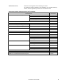
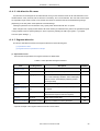
Related Documents
Read this manual together with the following documents.
The related documents indicated in this publication may include preliminary
versions. However, preliminary versions are not marked as such.
Documents related to development tools (user’s manuals)
Document Name
CA850 Ver. 3.20 C Compiler Package
Document No.
Operation
U18512E
C Language
U18513E
Assembly Language
U18514E
Link Directives
This manual
U18416E
PM+ Ver. 6.30 Project Manager
ID850 Ver. 3.00 Integrated Debugger
Operation
U17358E
ID850NW Ver. 3.10 Integrated Debugger
Operation
U17369E
ID850QB Ver. 3.20 Integrated Debugger
Operation
U17964E
SM+ System Simulator
Operation
U17246E
User Open Interface
U18212E
SM850 Ver. 2.50 System Simulator
Operation
U16218E
SM850 Ver. 2.00 or Later System Simulator
External Part User Open Interface Specifications
U14873E
RX850 Ver. 3.20 or Later Real-Time OS
Basics
U13430E
Installation
U17419E
Technical
U13431E
Task Debugger
U17420E
Basics
U18165E
Internal Structure
U18164E
Task Debugger
U17422E
Functionalities
U16643E
Internal Structure
U16644E
Task Debugger
U16811E
RX850 Pro Ver. 3.21 Real-Time OS
RX850V4 Ver. 4.22 Real-Time OS
AZ850 Ver. 3.30 System Performance Analyzer
U17423E
AZ850V4 Ver. 4.10 System Performance Analyzer
U17093E
TW850 Ver. 2.00 Performance Analysis Tuning Tool
U17241E
User’s Manual U18515EJ1V0UM
7
[MEMO]
8
User’s Manual U18515EJ1V0UM
CONTENTS
CHAPTER 1 OVERVIEW ... 14
1. 1 Functional Outline ... 14
1. 2 System Configuration ... 15
1. 3 Operating Environment ... 16
CHAPTER 2 INSTALLATION ... 17
2. 1 Installing LDG ... 17
2. 2 Folder Configuration ... 17
2. 3 Uninstalling LDG ... 17
CHAPTER 3 STARTING AND EXITING ... 18
3. 1 Starting LDG ... 18
3. 2 Exiting ... 18
CHAPTER 4 GENERATION METHOD ... 19
4. 1 Generation Procedure ... 19
4. 2 Setting Development Environment ... 20
4. 2. 1 Creating new link directive file ... 20
4. 2. 2 Editing existing link directive file ... 20
4. 3 Editing ... 21
4. 3. 1 Adding memory ... 21
4. 3. 2 Adding section ... 21
4. 3. 3 Adding object file ... 21
4. 4 Saving ... 22
4. 4. 1 Format of link directive file ... 22
CHAPTER 5 WINDOW REFERENCE ... 23
5. 1 Overview of Window and Dialog Boxes of LDG ... 23
5. 2 Explanation of Window and Dialog Boxes ... 24
Main window ... 25
[New Link Directive] dialog box ... 44
[Select Development Environment] dialog box ... 46
[Open] dialog box ... 48
[Save As] dialog box ... 50
[Find] dialog box ... 52
User’s Manual U18515EJ1V0UM
9
[Select Object File] dialog box ... 54
[Add Memory] dialog box ... 56
[Add Section] dialog box ... 59
[Add Symbol] dialog box ... 63
[Option] dialog box ... 66
CHAPTER 6 MESSAGES ... 70
6. 1 Display Format ... 70
6. 2 Error Message ... 71
6. 3 Warning Message ... 71
6. 4 Question Message ... 73
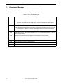
6. 5 Information Message ... 74
APPENDIX A LINK DIRECTIVE ... 75
A. 1 Overview ... 75
A. 1. 1 Specification Items ... 75
A. 2 Sections and Segments ... 77
A. 2. 1 Sections ... 77
A. 2. 2 Segments ... 77
A. 2. 3 Relationship between segments and sections ... 79
A. 2. 4 Types of sections ... 79
A. 2. 5 Relationship between types and attributes of sections ... 84
A. 3 Symbols ... 86
A. 3. 1 Text pointer (tp) ... 86
A. 3. 2 Global pointer (gp) ... 87
A. 3. 3 Element pointer (ep) ... 90
A. 4 Link Directive Format ... 92
A. 4. 1 Characters used in link directive file ... 92
A. 4. 2 Link directive file name ... 93
A. 4. 3 Segment directive ... 93
A. 4. 4 Mapping directive ... 99
A. 4. 5 Symbol directive ... 107
A. 5 Defaults ... 112
A. 6 Link Directive File Coding Examples ... 113
INDEX ... 122
10
User’s Manual U18515EJ1V0UM
LIST OF FIGURES
Figure No.
1-1
Title and Page
System Configuration Example ... 15
2-1
Folder Configuration ... 17
3-1
Main Window on Starting LDG ... 18
4-1
Generation Procedure of Link Directive File ... 19
5-1
Main Window ... 25
5-2
Example of Memory Mapping View Area ... 26
5-3
Example of Displayed Contents of Memory ... 27
5-4
Example of Displayed Contents of Mirror Image (If Each Memory Is Not Displayed) ... 28
5-5
Example of Displayed Contents of Section ... 29
5-6
Example of Displayed Contents of Object File ... 30
5-7
Example of Displayed Contents of Symbol ... 31
5-8
Property View Area (When Section Is Selected) ... 36
5-9
Example of Message View Area ... 39
5-10
[New Link Directive] Dialog Box ... 44
5-11
[Select Development Environment] Dialog Box ... 46
5-12
[Open] Dialog Box ... 48
5-13
[Save As] Dialog Box ... 50
5-14
[Find] Dialog Box ... 52
5-15
[Select Object File] Dialog Box ... 54
5-16
[Add Memory] Dialog Box ... 56
5-17
[Add Section] Dialog Box ... 59
5-18
[Add Symbol] Dialog Box ... 63
5-19
[Option] Dialog Box (When [Font] Is Selected) ... 66
5-20
Setting of [Font] in [Option] Dialog Box ... 67
5-21
Setting of [Color] in [Option] Dialog Box ... 68
5-22
Setting of [Whole] in [Option] Dialog Box ... 68
6-1
Example of Message Dialog Box ... 70
A-1
Segment Directives and Mapping Directives ... 75
A-2
Symbol Directive ... 76
A-3
Relation Between Segments and Sections ... 79
A-4
Example of Memory Allocation to Various Sections by CA850 (With Internal ROM) ... 83
A-5
Example of tp Setting ... 86
A-6
Example of gp Setting (When Specifying Segment) ... 87
A-7
Example of gp Setting (When Specifying Offset from tp) ... 88
A-8
Rules for Determining Global Pointer Values ... 89
A-9
Example of ep Setting ... 90
A-10
Rules for Determining Element Pointer Values ... 91
User’s Manual U18515EJ1V0UM
11
LIST OF TABLES
Table No.
Title and Page
5-1
Window and Dialog Boxes of LDG ... 23
5-2
Displayed Contents of Memory ... 27
5-3
Displayed Contents of Mirror Image Area ... 28
5-4
Relationship Between Memory Attribute and Background Color (Default) ... 28
5-5
Displayed Contents of Section ... 29
5-6
Relationship Between Section Attribute and Background Color (Default) ... 30
5-7
Displayed Contents of Section ... 31
5-8
Items That Can Be Directly Edited in Mapping View Area and Notes ... 32
5-9
Editing by Drag-and-Drop Operation ... 35
5-10
Displayed Contents in Property View Area and Editing Availability (When Memory Is Selected) ... 36
5-11
Displayed Contents in Property View Area and Editing Availability (When Section Is Selected) ... 37
5-12
Displayed Contents in Property View Area and Editing Availability (When Group Is Selected) ... 37
5-13
Displayed Contents in Property View Area and Editing Availability (When Object File Is Selected) ... 38
5-14
Displayed Contents in Property View Area and Editing Availability (When Symbol Is Selected) ... 38
5-15
Toolbar of Main Window ... 43
5-16
Function Buttons of [New Link Directive] Dialog Box ... 45
5-17
Function Buttons of [Select Development Environment] Dialog Box ... 47
5-18
Function Buttons of [Open] Dialog Box ... 49
5-19
Function Buttons of [Save As] Dialog Box ... 51
5-20
Function Buttons of [Find] Dialog Box ... 53
5-21
Function Buttons of the [Select Object File] Dialog Box ... 55
5-22
Function Buttons of [Add Memory] Dialog Box ... 58
5-23
Function Buttons of [Add Section] Dialog Box ... 62
5-24
Function Buttons of [Add Symbol] Dialog Box ... 65
5-25
Categories in [Option] Dialog Box ... 67
5-26
Function Buttons of [Option] Dialog Box ... 69
6-1
Message Types ... 70
6-2
List of Error Message ... 71
6-3
List of Warning Message ... 71
6-4
List of Question Message ... 73
6-5
List of Information Message ... 74
A-1
CA850 Allocation Section Types ... 80
A-2
Section Types ... 84
A-3
Section Attributes ... 84
A-4
Types of Sections ... 85
A-5
Items Specified in Segment Directive ... 93
A-6
Default Values for Omitted Segment Directive Specification Items ... 94
A-7
Reserved Section Names with Fixed Segment Names ... 94
A-8
Segment Attributes and Their Meanings ... 95
A-9
Segment Example ... 97
A-10
Items Specified in Mapping Directive ... 99
12
User’s Manual U18515EJ1V0UM
A-11
Default Values/Conventions for Values That Can Be Omitted in Mapping Directive Specification Items ... 100
A-12
Input Section Names with Fixed Section Names ... 100
A-13
Section Types ... 101
A-14
Section Attributes and Their Meanings ... 101
A-15
Section Types and Default Values for Alignment Condition ... 102
A-16
Output Based on Combination of Input Section and Object File Specifications ... 103
A-17
Specific Examples of Combined Input Section and Object File Specifications ... 103
A-18
Mapping Directive Specification Example ... 106
A-19
Specifiable Items When Creating tp Symbol ... 107
A-20
Default Values for tp Symbols ... 107
A-21
Specifiable Items When Creating gp Symbol ... 108
A-22
Default Values for gp Symbols ... 108
A-23
Specifiable Items When Creating ep Symbol ... 109
A-24
Default Values for ep Symbols ... 109
A-25
Address Specification for tp Symbol and gp Symbol ... 110
A-26
Segment Names Targeted for Reference by tp Symbol and gp Symbol ... 111
A-27
Symbol Directive Specification Example ... 111
User’s Manual U18515EJ1V0UM
13
CHAPTER 1 OVERVIEW
CHAPTER 1
OVERVIEW
1. 1 Functional Outline
In an embedded application system, many considerations must be given in allocating memory in order to satisfy the
specifications of the target device, such as allocating program codes and data to or separating them from certain
addresses.
The Link Directive Generator (LDG) is a tool that automatically generates or edits a link directive file through a GUI
in which such memory allocation information (including section information) is described.
By using the functions of the LDG that visually display the address space of the target device and image of allocation
of the addresses of the executable object file output by a linker, a link directive file can be generated and edited
smoothly and efficiently.
The major functions of the LDG are as follows:
- Graphical mapping display
Graphically displays the physical memory mapping and section mapping of the target device to be used, object file
names included in each section, and the section-related symbol names, as one view.
- Automatic generation/editing of link directive file through GUI operation
By dragging a section name, object file name, or symbol name with the mouse, allocation and assignment of it can
be visually edited.
- Re-editing/updating existing link directive file
A link directive file that was created by a tool other than the LDG can also be read.
14
User’s Manual U18515EJ1V0UM
CHAPTER 1 OVERVIEW
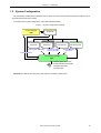
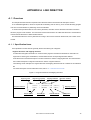
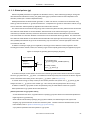
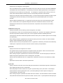
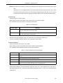
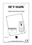
1. 2 System Configuration
The LDG obtains address space information from a device file, and section information/symbol information from an
object file/execution file (ELF format).
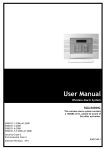
An example of the system configuration of the LDG is illustrated below.
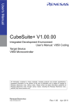
Figure 1-1 System Configuration Example
Project manager
PM+
Device file
Project file
Object file
Address space information
Execution file
Section information
Symbol information
Project information
Link directive file
Section allocation
information
Link directive generator
LDG
- Address space information
- Section allocation information
- Compiler information
- OS information
[Remark] The LDG can also operate by itself, without coordinating with the PM+.
User’s Manual U18515EJ1V0UM
15
CHAPTER 1 OVERVIEW
1. 3 Operating Environment
The following environments are required in order to use LDG.
(1) Host machine
CPU
: Pentium IITM 400MHz or higher
Memory
: 128 Mbytes or more
OS
: Windows® 2000, Windows XP Professional, Windows XP Home Edition
[Caution] Regardless of which OS is used, higher and the latest Service Pack must be installed.
(2) Software
- Compiler
CA850 Ver.3.00 or later
- Device file
Device file of the target device to be used
- Development tool (if necessary)
PM+ Ver.6.00 or later
16
User’s Manual U18515EJ1V0UM
CHAPTER 2 INSTALLATION
CHAPTER 2
INSTALLATION
2. 1 Installing LDG
LDG is included with a compiler package (CA850).
When CA850 is installed, LDG can be also installed if necessary, as it is supplied in the same package.
For the details on how to install the CA850, refer to "CA850 C Compiler Package Operation User’s Manual".
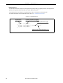
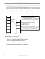
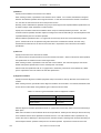
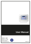
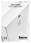
2. 2 Folder Configuration
The folders are configured as a result of installing the LDG are as follows.
Figure 2-1 Folder Configuration
Installation destination folder (default: C:\Program Files\NEC Electronics Tools\LDG\Vx.xx)
bin
Execution file, DLL file, resource file, etc.
doc
Document-related file (*.pdf / *.txt)
hlp
Help file (*.chm)
A shortcut for the LDG (default: [Program] -> [NEC Electronics Tools] -> [LDG] -> [Vx.xx] -> [LDG Vx.xx]) is
automatically added to the Windows start menu.
2. 3 Uninstalling LDG
To uninstall LDG, start "Add or Remove Programs" ("Add/Remove Programs" in Windows other than Windows XP)
on the Control Panel of Windows and select the following items.
- NEC EL LDG Vx.xx
- NEC EL LDG Vx.xx Documents
User’s Manual U18515EJ1V0UM
17
CHAPTER 3 STARTING AND EXITING
CHAPTER 3
STARTING AND EXITING
3. 1 Starting LDG
The LDG can be started in the following three ways.
(1) Starting from the shortcut in the Windows start menu
Select Windows start menu -> [Program] -> [NEC Electronics Tools] -> [LDG] -> [Vx.xx] -> [LDG vx.xx] (default).
(2) Starting from PM+
Select the [Tool] menu -> [Startup LDG] from the main window of the PM+.
(3) Double-clicking execution file of LDG
Directly double-click the execution file of the LDG as follows:
C:\Program Files\NEC Electronics Tools\LDG\Vx.xx\bin\LDG.exe (default)
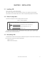
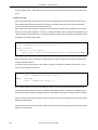
When the LDG is started, the following Main window is opened.
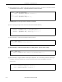
Figure 3-1 Main Window on Starting LDG
[Caution] If the LDG is not started from PM+, "project information" (information of object files, etc., that configure a
project) set on PM+ cannot be used with the LDG.
3. 2 Exiting
To exit the LDG, select the [File] menu -> [Exit] from the Main window.
18
User’s Manual U18515EJ1V0UM
CHAPTER 4 GENERATION METHOD
CHAPTER 4
GENERATION METHOD
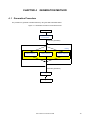
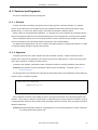
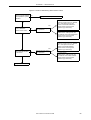
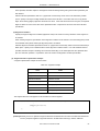
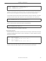
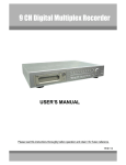
4. 1 Generation Procedure
The procedure to generate a link directive file by using the LDG is illustrated below.
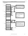
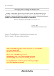
Figure 4-1 Generation Procedure of Link Directive File
Starting LDG
Setting Development
Environment
(Automatic generation)
Editing
Adding memory
Adding section
Adding object file
(Automatic generation)
Saving (*.lnd)
Exiting LDG
User’s Manual U18515EJ1V0UM
19
CHAPTER 4 GENERATION METHOD
4. 2 Setting Development Environment
Set the development environment of the link directive file to be created or edited.
4. 2. 1 Creating new link directive file
Create a new link directive file in the following procedure.
(1) Select [File] menu -> [New...].
Open the [New Link Directive] dialog box by selecting the [File] menu -> [New...] from the Main window.
(2) Set the details of the development environment.
Specify the name of the device and compiler to be used, and, as necessary, the name of the real-time OS.
(3) Click [OK] button.
After completing the necessary setting, click the [OK] button.
The internal ROM/RAM area corresponding to the specified device and allocation of sections that are absolutely
necessary and sections necessary for the real-time OS will be reflected in the Main window.
[Remark] If the LDG is started from PM+, the [New Link Directive] dialog box is opened with the development
environment of PM+ (project information) reflected.
4. 2. 2 Editing existing link directive file
Edit an existing link directive file that was created with a tool other than the LDG in the following procedure.
(1) Select [File] menu -> [Open...].
Open the [Open] dialog box by selecting the [File] menu -> [Open...] from the Main window, and select a link
directive file to be edited.
(2) Set the details of the development environment.
Next, specify the name of the device and the name of the compiler to be used in the [Select Development
Environment] dialog box that is automatically opened.
(3) Click [OK] button.
After completing the necessary setting, click the [OK] button.
The internal ROM/RAM area corresponding to the specified device and allocation of sections that are absolutely
necessary and sections necessary for the real-time OS will be reflected in the Main window.
[Remark] If the LDG is started from PM+, a link directive file is opened with the development environment of PM+
(project information) automatically reflected (the [Select Development Environment] dialog box is not
opened).
20
User’s Manual U18515EJ1V0UM
CHAPTER 4 GENERATION METHOD
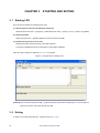
4. 3 Editing
4. 3. 1 Adding memory
If a memory other than the internal memory of the device is to be used, add the new memory in the following
procedure.
(1) Select [Edit] menu -> [Add] -> [Memory].
Open the [Add Memory] dialog box by selecting the [Edit] menu -> [Add] -> [Memory] from the Main window.
(2) Set detailed information for the memory.
Specify the type (ROM/RAM), start address, size, and alignment of the memory to be newly added, and then
click the [OK] button.
4. 3. 2 Adding section
Allocate a new section, if necessary, in the following procedure.
(1) Select [Edit] menu -> [Add] -> [Section].
Select a memory to which a new section is to be allocated in the Memory mapping view area in the Main
window, and open the [Add Section] dialog box by selecting the [Edit] menu -> [Add] -> [Section].
(2) Set detailed information for the section.
Set the access type (read only, read write, or instruction code), section name, allocation method (address
specification or allocating following preceding section) to be newly added, and then click the [OK] button.
[Remark] If sections are allocated in overlapping areas, allocate the additional section in the mirror area.
The mirror area can be displayed by checking the [View] menu -> [Show Mirror Image] (this is checked by
default).
4. 3. 3 Adding object file
Add an object file (*.o) or execution file (*.out) to be linked in the following procedure.
The LDG reads section information from a specified object file and allocates it to the memory. It also checks the size
of the section.
(1) Select [File] menu -> [Select Object(s)...].
Open the [Open] dialog box by selecting the [File] menu -> [Select Object(s)...] from the Main window, select an
object file (*.o) or execution file (*.out) to be linked, and then click the [OK] button.
Two or more object files may be selected.
User’s Manual U18515EJ1V0UM
21
CHAPTER 4 GENERATION METHOD
4. 4 Saving
When all of the editing has been completed, save the link directive file in the procedure below.
The LDG saves the link directive file, appending information on the added memory and section.
(1) Select [File] menu -> [Save As...].
Open the [Save As] dialog box by selecting the [File] menu -> [Save As...] from the Main window, specify the
name of the file to be saved (*.lnd), and then click the [OK] button.
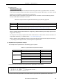
4. 4. 1 Format of link directive file
To the link directive file generated by the LDG, device information, memory information, and comments are added in
the comment format.
The character codes are stored as "shift JIS codes" and the carriage return code is stored as "CR+LF".
[Caution] If the device information or memory information the LDG has output to the link directive file is edited, the
link directive file may not be correctly read.
[Remark] Information peculiar to the LDG is not added to a link directive file if the check is removed from the [Output
LDG Information] check box in the [Save As] dialog box when the file is generated.
22
User’s Manual U18515EJ1V0UM
CHAPTER 5 WINDOW REFERENCE
CHAPTER 5
WINDOW REFERENCE
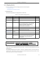
5. 1 Overview of Window and Dialog Boxes of LDG
The LDG has the following window and dialog boxes.
Table 5-1 Window and Dialog Boxes of LDG
Window/Dialog Box
Functional Outline
Main window
This window is used for basic operation of the LDG.
In this window, the physical memory mapping and section
mapping of the target device, object file names included in each
section, and related symbol names are displayed and edited.
[New Link Directive] dialog box
Generates a new link directive file.
[Select Development Environment] dialog box
Sets a new environment if an existing link directive file that has
been created by a tool other than the LDG is opened.
[Open] dialog box
Specifies a file to be read by the LDG.
[Save As] dialog box
Saves edited file, giving a name to it.
[Find] dialog box
Searches a memory name, section name, or object file name,
or searches a character string in a message output by the LDG.
[Select Object File] dialog box
Adds a new object file.
[Add Memory] dialog box
Adds a new memory.
[Add Section] dialog box
Adds a new section.
[Add Symbol] dialog box
Adds a new symbol.
[Option] dialog box
Makes basic setting related to operation and display of the
LDG.
User’s Manual U18515EJ1V0UM
23
CHAPTER 5 WINDOW REFERENCE
5. 2 Explanation of Window and Dialog Boxes
This section explains the window and dialog boxes of the LDG in the following format.
Window/dialog box name
The name of the window or dialog box is shown in the frame.
The display image and functional outline of the window or dialog box, and how to open the window or dialog box are
explained here.
Explanation of each area
Each area of the window or dialog box is explained.
Menubar
Menu items that can be pulled down from the concerned item on the menu bar are enumerated and each function is
explained.
Toolbar
The function of each button on the toolbar is explained.
Function buttons
The operation of each button in the dialog box is explained.
Others
The special functions of the window or dialog box, if any, and how to use those functions are explained.
Note on operation
Points to be noted when operating the window or dialog box are enumerated.
24
User’s Manual U18515EJ1V0UM
CHAPTER 5 WINDOW REFERENCE
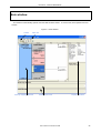
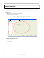
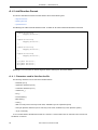
Main window
This window is automatically opened when the LDG has been started. To use the LDG, start operation from this
window.
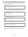
Figure 5-1 Main Window
Toolbar
Menu bar
Memory mapping view area
Message view area
User’s Manual U18515EJ1V0UM
Property view area
25
CHAPTER 5 WINDOW REFERENCE
The following items are explained below.
- Memory mapping view area
(1) Displayed contents of each item
(2) Editing through keyboard operation
- Property view area
- Message view area
- Menu bar
(1) [File] menu
(2) [Edit] menu
(3) [View] menu
(4) [Tool] menu
(5) [Help] menu
- Toolbar
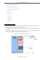
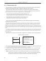
Memory mapping view area
This area is used to display and edit the physical memory mapping and section mapping of the target device, and
object file name included in each section and related symbol name.
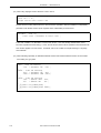
The view area can be divided into two parts, upper and lower, by dragging the division bar at the upper part of the
vertical scroll bar.
In this area, all the addresses are displayed as hexadecimal numbers. If an address is of less than the specified
number of digits, it is padded with "0". One blank is inserted in every 4 digits.
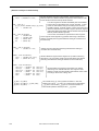
Figure 5-2 Example of Memory Mapping View Area
Division bar
26
User’s Manual U18515EJ1V0UM
CHAPTER 5 WINDOW REFERENCE
(1) Displayed contents of each item
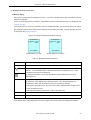
(a) Memory display
Each memory of each attribute is displayed as a box. In each box, a memory name, size, start address, and end
address are displayed.
If a box is clicked, that memory is selected. The detailed information of the selected memory is displayed in the
Property view area.
If the mouse cursor is moved onto a memory name, the detailed information of that memory pops up for display
(the displayed contents are the same as those displayed in the property view area). The pop-up display time can
be changed in the [Option] dialog box.
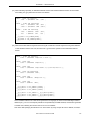
Figure 5-3 Example of Displayed Contents of Memory
Start address
Memory name
Size
End address
Memory name
Size
End address
Start address
(If start address is at top)
(If start address is at bottom)
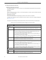
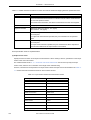
Table 5-2 Displayed Contents of Memory
Item
Memory name
Description
Displays a name to identify the memory.
These marks are displayed on the left of the memory name if a section is allocated to the
memory. "+" mark indicates that the allocated sections are not displayed, and "-" mark
indicates that the sections are displayed.
By clicking these marks, it can be specified whether the allocated sections are to be
displayed or not.
Size
Displays the size (bytes) of the memory.
By default, the size is displayed as a decimal number. It can also be displayed as a
hexadecimal number with "0x" prefixed by either of the following methods.
- Select [Show Size With Hex] on the context menu that is displayed when the right mouse
button is clicked in the box.
- Select the box and select [View] menu -> [Show Size With Hex].
Start address
Displays the start address of the memory area as a hexadecimal number with "0x" prefixed.
End address
Displays the end address of the memory area as a hexadecimal number with "0x" prefixed.
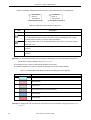
If the address space of the target device has mirror images, each mirror image area is displayed as follows.
User’s Manual U18515EJ1V0UM
27
CHAPTER 5 WINDOW REFERENCE
Figure 5-4 Example of Displayed Contents of Mirror Image (If Each Memory Is Not Displayed)
Start address
End address
Mirror N
Mirror N
End address
Start address
(If start address is at top)
(If start address is at bottom)
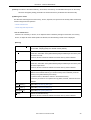
Table 5-3 Displayed Contents of Mirror Image Area
Item
Mirror N
Description
"N" indicates the number (from 0) of a mirror image.
These marks indicate whether each memory in the mirror image is displayed.
"+" mark indicates that the memory in the mirror image is not displayed, and "-" mark
indicates that the memory in the mirror image is displayed.
By clicking these marks, it can be selected whether each memory in the mirror image is
displayed or not.
Start address
Displays the start address of the mirror image area as a hexadecimal number with "0x"
prefixed.
End address
Displays the end address of the mirror image area as a hexadecimal number with "0x"
prefixed.
[Remark] It can be specified whether the mirror image is to be displayed or not by selecting the [View] menu ->
[Show Mirror Image] or [Whole] in the [Option] dialog box.
The background color of each box indicates the attribute of the memory.
The relationship between the memory attribute and background color is as follows (default).
Table 5-4 Relationship Between Memory Attribute and Background Color (Default)
Background Color
Attribute
External ROM
External RAM
Vacant area
Area where memory cannot be allocated
Internal ROM
Internal RAM
[Remark] The background color and character color of the box can be specified by using [Color] of the [Option]
dialog box.
28
User’s Manual U18515EJ1V0UM
CHAPTER 5 WINDOW REFERENCE
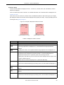
(b) Section display
A section of each attribute is displayed as a box. In each box, a section name, size, start address, and end
address are displayed.
If a box is clicked, that section is selected. The detailed information of the selected section is displayed in the
Property view area.
If the mouse cursor is moved onto a section name, the detailed information of that section pops up for display
(the displayed contents are the same as those displayed in the property view area). The pop-up display time can
be changed in the [Option] dialog box.
Figure 5-5 Example of Displayed Contents of Section
Start address
Section name
Size
End address
Section name
Size
End address
Start address
(If start address is at top)
(If start address is at top)
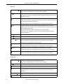
Table 5-5 Displayed Contents of Section
Item
Section name
Description
Displays a section name.
These marks are displayed on the left of the section name if an object file is read. "+" mark indicates
that the target object file are not displayed, and "-" mark indicates that the target object files are
displayed.
By clicking these marks, it can be specified whether the target object files are to be displayed or not.
Size
Displays the size (bytes) of the section.
By default, the size is displayed as a decimal number. It can also be displayed as a
hexadecimal number with "0x" prefixed by either of the following methods.
- Select [Show Size With Hex] on the context menu that is displayed when the right mouse
button is clicked in the box.
- Select the box and select the [View] menu -> [Show Size With Hex].
Start address
Displays the start address of the section as a hexadecimal number with "0x" prefixed.
If the section is allocated following the preceding section, the start address is displayed in "(
)".
If the section starts from the start address, this mark is displayed to the left of the start
address.
If the section follows the preceding section, this mark is displayed to the left of the start
address.
End address
Displays the end address of the section as a hexadecimal number with "0x" prefixed.
If the section is allocated following the preceding section, the end address is displayed in "(
)".
User’s Manual U18515EJ1V0UM
29
CHAPTER 5 WINDOW REFERENCE
[Caution] "?" is displayed instead of the item concerned in the following cases.
- [Size] if the size of the section cannot be obtained
- [Start address] and [End address] if the size of the section cannot be obtained and if the section is
allocated following other section
- Size of the contiguous sections adjacent in the direction of the start address or [Size] and [Start
address] of a vacant area if the start address is not determined
The background color of each box indicates the attribute of the section.
The relationship between the section attribute and background color is as follows (default).
Table 5-6 Relationship Between Section Attribute and Background Color (Default)
Background Color
Attribute
In Mirror Image
Instruction code
Vacant area
Section other than above
[Remark] The background color and character color of the box can be specified by using [Color] of the [Option]
dialog box, according to a section type (with or without initial value) or an access type.
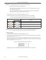
(c) Object file display
The object file names included in each section are displayed in a box.
When an object file name is clicked, that object file is selected. The detailed information of the selected object
file is displayed in the Property view area.
If the mouse cursor is moved onto an object file name, the detailed information of that object file pops up for
display (the displayed contents are the same as those displayed in the property view area). The pop-up display
time can be changed in the [Option] dialog box.
Figure 5-6 Example of Displayed Contents of Object File
Object file name 1
Object file name 2
Object file name 3
Object file name 4
[Caution] The sequence of displaying the object file affects the sequence of the resolving link.
30
User’s Manual U18515EJ1V0UM
CHAPTER 5 WINDOW REFERENCE
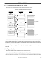
(d) Symbol display
Symbol names related to a section are displayed in a box.
Symbols are displayed only when the linker can generate symbols related to a section.
Each symbol is displayed connected to the related memory and section with lines. A symbol related to two or
more memories or sections is displayed connected to those memories and sections with lines.
A symbol that starts from the break of a memory or a section is displayed with the top and bottom sides of the
box indicating the memory or section connected with a line.
Figure 5-7 Example of Displayed Contents of Symbol
Address
Symbol name
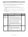
Table 5-7 Displayed Contents of Section
Item
Address
Description
Displays the address of the symbol. If the address cannot be obtained, however, "?" is
displayed. If the address of the symbol can be obtained, this box is displayed where the
address is. If the address cannot be obtained, it is displayed at the center right of the box of
the related memory or section.
Symbol name
Displays the name of the symbol.
User’s Manual U18515EJ1V0UM
31
CHAPTER 5 WINDOW REFERENCE
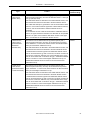
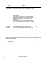
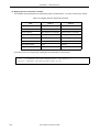
(2) Editing through keyboard operation
(a) Editing through keyboard operation
The contents of each item in a memory or section can be directly edited through keyboard input by performing
the following operation.
[Operation]
Click a box indicating a memory or section. The box will be selected. If an item in the box is clicked in this status
again, it can be directly edited.
[Determining new value]
A new value is determined when the [Enter] key is pressed or when the item is unselected.
If an illegal value is specified, however, the selection cannot be canceled. In this case, a message is displayed in
the Message view area.
The items that can be edited by the above operation and the points to be noted in doing so are listed below.
Table 5-8 Items That Can Be Directly Edited in Mapping View Area and Notes
Item
Note
Memory
Memory name
The first character must be an alphabetic character.
The second character and those that follow must be alphanumeric characters.
Size
- [End address] is changed as necessary.
- If the size of memory is reduced, a vacant area is displayed between the memory
area of the end address and the adjacent memory area.
- If a memory area that overlaps the higher address does not exist after editing, the
[Start address] of vacant area is changed.
- If a memory area that overlaps the higher address exists after editing, the change is
not applied and a message is displayed in the message area.
Start address
If the memory area overlaps another memory area as a result of editing, the change is
not applied and a message is displayed in the message area.
End address
- [Size] is changed in accordance with the change.
- If the lower end address is specified, a vacant area is displayed between the memory
area of the end address and the adjacent memory area.
- If a memory area that overlaps the higher address does not exist after editing, the
[Start address] of vacant area is changed.
- If a memory area that overlaps the higher address exists after editing, the change is
not applied and a message is displayed in the message area.
Section
Section name
None
Start address
If the section area overlaps another section area as a result of editing, the change is
not applied and a message is displayed in the message area.
32
User’s Manual U18515EJ1V0UM
CHAPTER 5 WINDOW REFERENCE
[Caution] The values of the internal memory, vacant area, and memory non-allocatable area (such as SFR area)
cannot be changed by editing (information of the internal memory is obtained from the device file).
(b) Editing via a mouse
The allocation and assignment of the memory, section, object file, and symbol can be visually edited via following
function using the mouse operation.
- Use of context menu
- Use of drag-and-drop function
- Use of context menu
If each box for a memory or section, or an object file name is clicked by the right mouse button, the memory,
section, or object file at the clicked position is selected, and the following context menu is displayed.
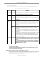
[Memory]
[Show Size With Hex]
Checked : Displays [Size] as a hexadecimal number.
Not checked : Displays [Size] as a decimal number (default).
[Cut]
Cuts the selected memory.
At this time, information of the [Start address] and [End address] of the memory that
has been cut is lost.
However, this item cannot be selected if a vacant memory area is selected.
[Copy]
Copies the selected memory to the copy buffer.
At this time, information of the [Start address] and [End address] of the memory that
has been copied is lost.
However, this item cannot be selected if a vacant memory area is selected.
[Paste]
To paste a memory, the memory must be pasted immediately next to the lower
address of the selected memory (if a vacant memory area is selected, paste the
memory to the [Start address] of that area).
To paste a section, allocate the section in the selected memory.
If a memory or section is not copied to the copy buffer, however, this item cannot be
selected.
[Add Memory...]
Opens the [Add Memory] dialog box.
[Add Section...]
Opens the [Add Section] dialog box.
[Add Symbol...]
Opens the [Add Symbol] dialog box.
[Delete]
Deletes the selected memory.
However, this item cannot be selected if a vacant memory area is selected.
User’s Manual U18515EJ1V0UM
33
CHAPTER 5 WINDOW REFERENCE
[Section]
[Show Size With Hex]
Checked : Displays [Size] as a hexadecimal number.
Not checked : Displays [Size] as a decimal number (default).
[Cut]
Cuts the selected section.
At this time, information of the [Start address] and [End address] of the section that
has been cut is lost.
[Copy]
Copies the selected section to the copy buffer.
At this time, information of the [Section name], [Start address], and [End address] of
the section that has been copied is lost.
However, this item cannot be selected if a vacant memory area is selected.
[Paste]
To paste a section, the section must be pasted immediately next to the lower
address of the selected section (if a vacant area is selected, paste the section to the
[Start Address] of that area).
To paste an object file, paste the object file to the selected section.
If a section or an object file is not copied to the copy buffer, however, this item
cannot be selected.
[Add Memory...]
Opens the [Add Section] dialog box.
[Add Section...]
Opens the [Select Object File] dialog box.
[Add Symbol...]
Opens the [Add Symbol] dialog box.
gp and tp symbols can be generated (a new ep symbol cannot be generated
because only one ep symbol can be generated).
[Delete]
Deletes the selected section from the memory.
However, this item cannot be selected if a vacant memory area is selected.
[Group]
Groups two or more of the selected sections (treats them as segments).
However, this item cannot be selected if two or more sections are not selected.
[Ungroup]
Cancels grouping of sections.
However, this item cannot be selected if grouped sections are not selected.
[Object file]
[Show Size With Hex]
Checked : Displays [Size] as a hexadecimal number.
Not checked : Displays [Size] as a decimal number (default).
[Cut]
Cuts the selected object file.
[Copy]
Copies the selected object file to the copy buffer.
[Paste]
Pastes an object file.
If an object file is not copied to the copy buffer, however, this item cannot be
selected.
34
[Select Object File...]
Opens the [Select Object File] dialog box.
[Delete]
Deletes the selected object file from the section.
User’s Manual U18515EJ1V0UM
CHAPTER 5 WINDOW REFERENCE
- Use of drag-and-drop function
Each box of a memory or section, or an object file name can be dragged and dropped by using the mouse.
Table 5-9 Editing by Drag-and-Drop Operation
Dragging
Source
Dropping
Destination
Memory
Memory
Operation
- Deletes the memory at the dragging source and allocates it before the memory
at the dropping destination.
However, the internal ROM and RAM cannot be dropped.
Section
Memory
- Deletes a section dragged from the memory at the dragging source and
allocates it to the memory at the dropping destination.
Section
- Allocates the section at the dragging source before the section at the dropping
destination.
Object file
name
Section
- If a section of the same attribute is at the dropping destination, deletes the
dragged object file and allocates it to the section at the dropping destination.
- If a section with a different attribute is at the dropping destination, the dragged
object file is not deleted and allocated to the section at the dropping
destination.
Object file
name
- If an object file with the same attribute is at the dropping destination, the
dragged object file is deleted and allocated to the section at the dropping
destination.
- If an object file with a different attribute is at the dropping destination, the
dragged object file is not deleted and allocated to the section at the dropping
destination.
- If the object file is dropped to other file name on the same section, it is moved
from the dragging source position to the dropping destination position. The
order in which object files are displayed here affects the order of resolution
when the linker is executed.
Symbol
Section
- If the symbol at the dragging source is generated, related to two or more
sections, the section at the dropping destination is added to the relation of the
symbol.
- If the symbol at the dragging source is generated, related to a single section,
the relation of the symbol is switched to the section at the dropping destination.
[Target] tp symbol and gp symbol
[Caution] The tp symbol can be dropped only to a section of text attribute, and the gp symbol can be dropped only
to a section with a data attribute.
The ep symbol cannot be dropped because the address cannot be resolved, related to a section or
memory other than SIDATA and internal RAM.
[Remark] Two or more memories, sections, and object files can be selected.
If items are clicked with the [Ctrl] key held down, the clicked items are selected one after another. If an
item is selected and another item is clicked with the [Shift] key held down, the items from the item
selected first to the one that is clicked are selected.
User’s Manual U18515EJ1V0UM
35
CHAPTER 5 WINDOW REFERENCE
Property view area
This area is used to display or edit the detailed information of an item (memory, section, or object file) selected in the
Memory mapping view area.
The detailed setting not displayed in the Memory mapping view area can be directly edited in this area.
Figure 5-8 Property View Area (When Section Is Selected)
Explanation and notes on the selected item are displayed.
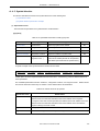
The displayed contents of the item selected in the Memory mapping view area, and whether the item can be edited
are shown below.
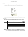
Table 5-10 Displayed Contents in Property View Area and Editing Availability (When Memory Is Selected)
Selected Item
Memory
Displayed Contents
Memory Name (The first character must be alphabetic and the second
character and those that follow must be alphanumeric.)
Editing
Availability
OK
Start Address
OK
End Address
OK
Size
OK
Type (ROM, RAM, vacant area, or memory non-allocatable area)
OK
Align (1 byte, 2 bytes, 4 bytes, or 8 bytes)
OK
Comment
OK
[Caution] The values of internal memory, vacant area, and memory non-allocatable area (such as an SFR area)
cannot be directly changed by editing (information of the internal memory is obtained from the device file).
36
User’s Manual U18515EJ1V0UM
CHAPTER 5 WINDOW REFERENCE
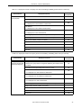
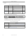
Table 5-11 Displayed Contents in Property View Area and Editing Availability (When Section Is Selected)
Selected Item
Section
(not grouped)
Displayed Contents
Editing
Availability
Section Name
OK
Preceding section (preceding section name or none)
OK
Start Address
"?" is displayed if no start address is determined.
End Address
"?" is displayed if no end address is determined.
Size
"?" is displayed if no size is determined.
OK
-
-
Access Type (instruction code, read only, or read/write)
OK
Section Type (with initial value or without initial value)
OK
Align (1 byte, 2 bytes, 4 bytes, or 8 bytes)
OK
Maximum Size
OK
Input Section
OK
Object File
-
Comment
OK
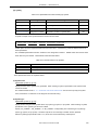
Table 5-12 Displayed Contents in Property View Area and Editing Availability (When Group Is Selected)
Displayed Contents
Editing
Availability
However, the group name of a segment defined by the CA850 cannot
OK
Selected Item
Group
(sections grouped and
treated as segment)
Group Name
be edited.
Preceding section (preceding section name or none)
Start Address
"?" is displayed if no start address is determined.
End Address
"?" is displayed if no end address is determined.
Size
"?" is displayed if no size is determined.
Access Type (instruction code, read only, or read/write)
Align (1 byte, 2 bytes, 4 bytes, or 8 bytes)
Maximum Size
Section
OK
OK
-
OK
OK
-
Comment
OK
User’s Manual U18515EJ1V0UM
37
CHAPTER 5 WINDOW REFERENCE
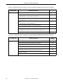
Table 5-13 Displayed Contents in Property View Area and Editing Availability (When Object File Is Selected)
Selected Item
Object file
Displayed Contents
File Name
Editing
Availability
-
Start Address
"?" is displayed if no start address is determined.
End Address
"?" is displayed if no end address is determined.
Size
"?" is displayed if no size is determined.
-
-
-
Section Type (with initial value or without initial value)
-
Path
-
Library
Not displayed if the object file is not included in the library file
Comment
OK
Table 5-14 Displayed Contents in Property View Area and Editing Availability (When Symbol Is Selected)
Selected Item
Symbol
Displayed Contents
Symbol Name
OK
Symbol Type (TP symbol, GP symbol, or EP symbol)
OK
Address
OK
Align (1 byte, 2 bytes, 4 bytes, or 8 bytes)
OK
Base Symbol
Not displayed if [Symbol type] is other than "GP symbol".
Reference Sections
Comment
38
Editing
Availability
OK
OK
User’s Manual U18515EJ1V0UM
CHAPTER 5 WINDOW REFERENCE
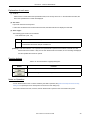
Message view area
This area displays messages to the user.
It is divided into two areas: one that displays history of all the messages that have been displayed (All Message
Histories) and the other that displays the latest message (Latest Message) (the size of these areas can be changed by
using the mouse).
Figure 5-9 Example of Message View Area
If the right mouse button is clicked on this area, the area below the mouse cursor is selected, and the following
context menu is displayed.
[Clear]
Clears the displayed message.
If the latest message area is selected, this item cannot be selected.
[Copy]
Copies a selected character string to the copy buffer.
If no character string is selected, this item cannot be selected.
[Find]
Opens the [Find] dialog box that is used to search a character string from the message log.
User’s Manual U18515EJ1V0UM
39
CHAPTER 5 WINDOW REFERENCE
Menu bar
(1) [File] menu
[New...]
Opens the [New Link Directive] dialog box to create a new link directive.
While a link directive is being edited, a message asking you whether it is
saved to a file is displayed. If "Save" is selected at this time, the operation is
[Ctrl]+[N]
the same as [Save].
[Open...]
Opens the [Open] dialog box.
If a link directive file created by a tool other than the LDG is used or if the link
directive file of a compiler that cannot describe comments in a link directive
file is used, the [Select Development Environment] dialog box is opened.
If the LDG has been started from PM+, however, the link directive file is
opened in the environment set on PM+ (for details of how the LDG files are
[Ctrl]+[O]
read, refer to the description of the [Open] dialog box.
If a file is being edited, a message asking you whether the file is to be saved
is displayed. If "Save" is selected at this time, the operation is the same as
[Save].
[Save]
Overwrites and saves a file.
If a file that has been newly created has never been saved, the operation is
[Ctrl]+[S]
the same as [Save As...].
[Save As...]
Opens the [Save As] dialog box.
The format of the file to be saved is *.lnd.
[Select Object(s)...]
-
Opens the [Select Object File] dialog box that is used to select an object file in
order to select object file(s) or execution file to be linked.
The type of the file that can be read is as follows.
- Execution file (*.out)
- Object file (*.o)
-
- Library (*.a)
While a file is being edited, a message asking you whether the file is saved is
displayed. If "Save" is selected at this time, the operation is the same as
[Save].
[History File Name]
Displays history of up to four files that have been used.
By selecting a file name, that file can be opened.
[Exit]
40
Quits the LDG.
User’s Manual U18515EJ1V0UM
-
CHAPTER 5 WINDOW REFERENCE
(2) [Edit] menu
[Undo]
Restores the editing operation immediately before.
However, this item cannot be selected if the operation cannot be restored.
[Cut]
Cuts the selected item.
[Copy]
Copies the selected item to the copy buffer.
[Ctrl]+[X]
The name information of the copy source will be lost.
[Paste]
[Ctrl]+[Z]
[Ctrl]+[C]
Pastes the contents of the copy buffer to a selected position.
If the memory to be pasted does not have a name, name "NewMemory" is assumed.
If the section to be pasted does not have a name, name "NewSection.section type" is
assumed.
[Ctrl]+[V]
If the same name already exists, a decimal number (0 to 4,294,967,295) is suffixed to
the specified name.
[Add]
Displays the following cascade menu to add an item to the Memory mapping view
-
area.
To add an object file, select the [File] menu -> [Select Object (s)...].
[Memory]
Opens the [Add Memory] dialog box that is used to add a memory.
-
[Section]
Opens the [Add Section] dialog box that is used to add a section.
-
[Symbol]
Opens the [Add Symbol] dialog box that is used to add a symbol.
-
[Delete]
Deletes the selected item.
[Group]
[Group]
Groups the selected sections.
-
[Ungroup]
Cancels the grouping of the sections.
-
[Joint]
Combines selected memories and treats them as one memory.
[Find...]
Opens the [Find] dialog box that is used to search a section, object file, or a character
string in the message log.
User’s Manual U18515EJ1V0UM
[Del]
[Ctrl]+[F]
41
CHAPTER 5 WINDOW REFERENCE
(3) [View] menu
[Toolbar]
Checked:
Displays the toolbar (default).
Not checked: Does not display the toolbar.
The checked status is saved when the LDG is terminated and is restored
-
when the LDG is started the next time.
[Show Size With Hex]
Checked:
Displays the memory size as a hexadecimal number.
Not checked: Displays the memory size as a decimal number (default).
The checked status is saved when the LDG is terminated and is restored
-
when the LDG is started the next time.
[Upside Down]
Checked:
Displays the memory map with the start address at
bottom.
Not checked: Displays the memory map with the start address at top
(default).
-
The checked status is saved when the LDG is terminated and is restored
when the LDG is started the next time.
[Show Mirror Image]
Checked:
Displays the mirror image (default).
Not checked: Does not display the mirror image.
The checked status is saved when the LDG is terminated and is restored
-
when the LDG is started the next time.
[Show All Memory Space]
Checked:
Checked: Linearly displays the whole memory area.
Sections are displayed only at the addresses where they
are allocated.
Not checked: The mirror image can be expanded or folded (default).
-
The checked status is saved when the LDG is terminated and is restored
when the LDG is started the next time.
[Clear Messages]
Clears the message displayed in the Message view area.
-
(4) [Tool] menu
[Option...]
Opens the [Option] dialog box that is used to make various setting of the
LDG (such as font and color of memory mapping).
-
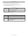
(5) [Help] menu
[LDG Help]
Opens the on-line help of the LDG.
[NEC Electronics Microcomputer Web]
Opens a NEC Electronics microcontroller-related Website.
[About...]
Displays the version information of the LDG.
Displays "LDG version number [day month year]".
42
User’s Manual U18515EJ1V0UM
F1
-
CHAPTER 5 WINDOW REFERENCE
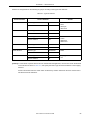
Toolbar
On the toolbar, buttons of menu items that are used relatively frequently are displayed. By selecting the button of a
menu item, the item can be executed.
Table 5-15 Toolbar of Main Window
Button
Function
Function same as selecting the [File] menu -> [New...]
Function same as selecting the [File] menu -> [Open...]
Function same as selecting the [File] menu -> [Save]
Function same as selecting the [Edit] menu -> [Cut]
Function same as selecting the [Edit] menu -> [Copy]
Function same as selecting the [Edit] menu -> [Paste]
Function same as selecting the [Edit] menu -> [Add]
User’s Manual U18515EJ1V0UM
43
CHAPTER 5 WINDOW REFERENCE
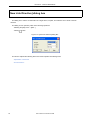
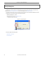
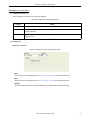
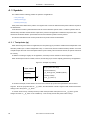
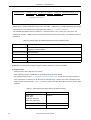
[New Link Directive] dialog box
This dialog box is used to set information of a target device, compiler, and real-time OS to create a new link
directive.
This dialog can be opened by either of the following operations.
- Selecting the [File] menu -> [New...]
- Clicking
button
Figure 5-10 [New Link Directive] Dialog Box
This section explains the following items.This section explains the following items.
- Explanation of each area
- Function buttons
44
User’s Manual U18515EJ1V0UM
CHAPTER 5 WINDOW REFERENCE
Explanation of each area
(1) Device
Select the name of a device to be used from the pull-down menu.
The LDG will determine the address space and internal memory area.
Specifying this item must not be omitted.
(2) Compiler
Select the name of a compiler to be used from the pull-down menu.
With this version of the LDG, only "CA850" can be selected.
Specifying this item must not be omitted.
(3) RTOS
Select the name of a real-time OS to be used from the pull-down menu.
The LDG will add the necessary sections.
When no real-time OS is used, select "Not Use".
[Remark] If the LDG is started from PM+, each of the items are displayed reflecting the setting of the project.
Function buttons
Table 5-16 Function Buttons of [New Link Directive] Dialog Box
Button
Function
Creates a new link directive file with the specified contents.
Ignores the setting and closes the dialog box.
Displays the on-line help of this dialog box.
User’s Manual U18515EJ1V0UM
45
CHAPTER 5 WINDOW REFERENCE
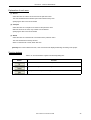
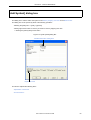
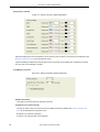
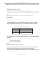
[Select Development Environment] dialog box
This dialog box is used to set a target device and compiler information when an existing link directive file (a link
directive file created by a tool other than the LDG or a link directive file that was saved with the check of [Output LDG
Information] on the [Save As] dialog box removed) is opened.
This dialog box can be opened by either of the following operations.
- Selecting the [File] menu -> [Open...] and then specifying an existing link directive file
- Clicking
button and then specifying an existing link directive file
Figure 5-11 [Select Development Environment] Dialog Box
This section explains the following items.
- Explanation of each area
- Function buttons
46
User’s Manual U18515EJ1V0UM
CHAPTER 5 WINDOW REFERENCE
Explanation of each area
(1) Device
Select the name of a device to be used from the pull-down menu.
The LDG will determine the address space and internal memory area.
Specifying this item must not be omitted.
(2) Compiler
Select the name of a compiler to be used from the pull-down menu.
With this version of the LDG, however, only "CA850" can be selected.
Specifying this item must not be omitted.
(3) RTOS
This area is always invalid.
Function buttons
Table 5-17 Function Buttons of [Select Development Environment] Dialog Box
Button
Function
Creates a new link directive file with the specified contents.
Ignores the setting and closes the dialog box.
Displays the on-line help of this dialog box.
User’s Manual U18515EJ1V0UM
47
CHAPTER 5 WINDOW REFERENCE
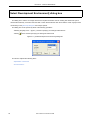
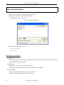
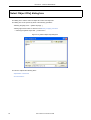
[Open] dialog box
This dialog box is used to select a file to be newly opened.
This dialog box can be opened by either of the following operations.
- Selecting the [File] menu -> [Open...]
- Clicking
button
Figure 5-12 [Open] Dialog Box
This section explains the following items.
- Explanation of each area
- Function buttons
- Notes on Operation
48
User’s Manual U18515EJ1V0UM
CHAPTER 5 WINDOW REFERENCE
Explanation of each area
(1) Look in:
Select a drive or folder where the specified file exists, from the drop-down list. In the area below this field, the
files in the specified drive or folder are displayed.
(2) File name:
Input a file name from the keyboard.
If a file name is selected from the area above this field, the select file name is displayed in this field.
(3) Files of type:
The following types of files can be selected.
- Link directive file (*.lnd, *dir)
*.lnd
File saved by the LDG including comment
*.dir
Standard link directive file of CA850
Link directive file used as sample of RX850 Pro
[Caution] If a file with extension ".dr" is opened, the specified file is opened if the contents of the file are a link
directive file of the CA850. If they are not a link directive file of the CA850, an error message is displayed
and the specified file cannot be opened.
Function buttons
Table 5-18 Function Buttons of [Open] Dialog Box
Button
Function
Opens the specified file and closes this dialog box.
Ignores the setting and closes this dialog box.
Notes on Operation
- If a link directive file that has not been created by the LDG is specified, the [Select Development Environment]
dialog box is opened (set a new development environment in this dialog box).
If the LDG is started from PM+, however, the link directive file is opened in the environment set by PM+.
User’s Manual U18515EJ1V0UM
49
CHAPTER 5 WINDOW REFERENCE
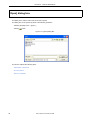
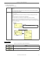
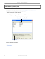
[Save As] dialog box
This dialog box is used to save a specified file by giving it a name.
This dialog box can be opened by the following operation.
- Selecting the [File] menu -> [Save As...]
Figure 5-13 [Save As] Dialog Box
This section explains the following items.
- Explanation of each area
- Function buttons
Explanation of each area
(1) Save in:
Select a drive or folder to which the file is to be saved, from the drop-down list. In the area below this field, the files
in the specified allocation are displayed.
(2) File name:
Input the name of the file to be saved from the keyboard.
If a file name is selected from the area above, the selected file name is displayed.
(3) Save as type:
Specify the type of the file to be saved, from the drop-down list.
However, the LDG can save only files with extension ".lnd".
50
User’s Manual U18515EJ1V0UM
CHAPTER 5 WINDOW REFERENCE
(4) Output LDG information
Check this check box as necessary.
Checked
Outputs information peculiar to the LDG and saves the specified file as a link directive file
(default).
If the file that has been saved in this way is read next time by the LDG, all the information
before the file is save is restored.
Not checked
Saves the link directive file without outputting information peculiar to the LDG, to improve the
legibility of the file.
To read the file saved in this way the next time by the LDG, the following points must be
noted.
- Memory information is not restored to the original status.
- Device information is not restored to the original status (must be re-selected).
- Regarding sections that were added before saving the file and were not grouped (into a
segment), a segment is read and displayed because the segment was automatically created
when the file was saved.
[Example]
-> File output
SEGMENT.text : !LOAD ?RX H0x0 F0x0 A0x8 {
.text = $PROGBITS ?AX A0x8;
};
Display when file is read again
Click "+".
Function buttons
Table 5-19 Function Buttons of [Save As] Dialog Box
Button
Function
Saves the file with the specified name and closes this dialog box.
Ignores the setting and closes this dialog box.
User’s Manual U18515EJ1V0UM
51
CHAPTER 5 WINDOW REFERENCE
[Find] dialog box
This dialog box is used to search for a character string from a memory name, section name, or object file name
displayed in the Memory mapping view area, or from the messages in the Message view area.
If a specified character string is found, the allocation where it has been found is selected and displayed in the area.
This dialog box can be opened by either of the following operations.
- Selecting the [Edit] menu -> [Find]
- Clicking right mouse button in Message view area
-> selecting the [Find] context menu
Figure 5-14 [Find] Dialog Box
Subject to search selection area
This section explains the following items.
- Explanation of each area
- Function buttons
52
User’s Manual U18515EJ1V0UM
CHAPTER 5 WINDOW REFERENCE
Explanation of each area
(1) Find What:
Specify a character string to be searched for.
Up to five character strings that have been searched after the LDG was started can be selected from the pull-down
menu.
(2) Subject to search selection area
This area is displayed only when the Memory mapping view area is selected.
In this area, select subject(s) (memory, section, or object file) for a search.
Only the checked subject(s) will be target for a search.
When this dialog box is opened for the first time after the LDG has been started, all the items are checked. When
the dialog box is opened the next time, the previous status is retained.
(3) Match Case
When this box is checked, only the upper and lower characters which exactly match the character string that is
designated in [Find What:] are searched for.
Function buttons
Table 5-20 Function Buttons of [Find] Dialog Box
Button
Function
Searches for the specified character string.
Ignores the setting and closes this dialog box.
Displays the on-line help of this dialog box.
User’s Manual U18515EJ1V0UM
53
CHAPTER 5 WINDOW REFERENCE
[Select Object File] dialog box
This dialog box is used to select an object file to add a new object file.
This dialog box can be opened by either of the following operations.
- Selecting the [File] menu -> [Select Object(s)...]
- Clicking right mouse button on section in the Memory mapping view area
-> selecting the [Select Object File...] context menu
Figure 5-15 [Select Object File] Dialog Box
This section explains the following items.
- Explanation of each area
- Function buttons
54
User’s Manual U18515EJ1V0UM
CHAPTER 5 WINDOW REFERENCE
Explanation of each area
(1) Look in:
Select a drive or folder where the specified file exists, from the drop-down list. In the area below this field, the files
in the specified drive or folder are displayed.
(2) File name:
Input the name of a file to be specified from the keyboard.
If a file name is selected from the area above, the selected file name is displayed in this field (two or more object
files may be selected).
(3) Files of type:
The following types of files may be selected.
- Execution file (*.out)
- Object file (*.o)
- Library file (*.a)
Function buttons
Table 5-21 Function Buttons of the [Select Object File] Dialog Box
Button
Function
Adds the specified object file and closes this dialog box.
Ignores the setting and closes this dialog box.
User’s Manual U18515EJ1V0UM
55
CHAPTER 5 WINDOW REFERENCE
[Add Memory] dialog box
This dialog box is used to add a new memory to the Memory mapping view area in the Main window.
This dialog box can be opened by either of the following operations.
- Selecting the [Edit] menu -> [Add] -> [Memory]
- Clicking right mouse button on memory in the Memory mapping view area
-> selecting the [Add Memory] context menu
Figure 5-16 [Add Memory] Dialog Box
Detailed information setting area
Explanation area
This section explains the following items.
- Explanation of each area
- Function buttons
56
User’s Manual U18515EJ1V0UM
CHAPTER 5 WINDOW REFERENCE
Explanation of each area
(1) Detailed information setting area
In this area, specify the value of each of the following items.
(a) Memory Name
Specify the name of the memory to be added.
The memory name must start with an alphabetic character. The second character and those that follow may be
alphanumeric characters.
By default, "NewMemory" is specified. If a memory of the same name already exists, a decimal number (0 to
4,294,967,295) is suffixed to the specified name.
(b) Start Address
Specify the start address of the memory to be added as a hexadecimal number with "0x" prefixed or a decimal
number.
If a memory is selected in the Memory mapping view area, an address to be added immediately before the
selected memory is specified by default.
If no memory is selected in the Memory mapping view area, an address to be added to the beginning of a vacant
address is specified by default.
In any of the following cases, the input value is assumed as illegal and a message is displayed.
- If the specified number of address digits is exceeded
- If [Start Address] is higher than [End Address]
- If the specified address overlaps other memory
(c) End Address
Specify the end address of the memory to be added as a hexadecimal number with "0x" prefixed or a decimal
number.
If a memory is selected in the Memory mapping view area, an address to be added immediately before the
selected memory is specified by default.
If no memory is selected in the Memory mapping view area, an address to be added to the beginning of a vacant
address is specified by default.
If the value of size is edited, the end address is automatically changed according to that value.
In any of the following cases, the input value is assumed as illegal and a message is displayed.
- If the specified number of address digits is exceeded
- If [Start Address] is higher than [End Address]
- If the specified address overlaps other memory
User’s Manual U18515EJ1V0UM
57
CHAPTER 5 WINDOW REFERENCE
(d) Size
Specify the size of the memory to be added as a hexadecimal number with "0x" prefixed or a decimal number.
By default, "0x1000 bytes" is specified. If the vacant area is less than 0x1000 bytes, however, the size of the
vacant area is specified.
If the value of [Start Address] or [End Address] is edited, the size is automatically changed according to that
value.
(e) Type
Specify either "ROM" or "RAM" as the type of the memory to be added.
"ROM" is specified by default.
(f) Align
Specify "1 byte", "2 bytes", "4 bytes", or "8 bytes" as align.
By default, "8 bytes" is specified.
(g) Comment
Specify a comment.
This field is blank by default.
(2) Explanation area
This area displays explanation of the item selected in the Detailed information setting area.
Function buttons
Table 5-22 Function Buttons of [Add Memory] Dialog Box
Button
Function
Adds new memory of the specified contents and closes this dialog box.
Adds new memory of the specified contents, but does not close this dialog box.
Cancels the specified contents.
Displays the on-line help of this dialog box.
58
User’s Manual U18515EJ1V0UM
CHAPTER 5 WINDOW REFERENCE
[Add Section] dialog box
This dialog box is used to add a new section to the Memory mapping view area on the Main window.
This dialog box can be opened by either of the following operations.
- Selecting the [Edit] menu -> [Add] -> [Section]
- Clicking the right mouse button on memory or section in the Memory mapping view area
-> selecting the [Add Section...] context menu
Figure 5-17 [Add Section] Dialog Box
Detailed information setting area
Explanation area
This section explains the following items.
- Explanation of each area
- Function buttons
User’s Manual U18515EJ1V0UM
59
CHAPTER 5 WINDOW REFERENCE
Explanation of each area
(1) Detailed information setting area
In this area, specify the value of each of the following items.
(a) Section Name
Specify the name of the section to be added.
Depending on the item selected in the Memory mapping view area, one of the following names is specified by
default.
Selected Item
Section Name (default)
Memory (RAM)
NewSection.data
Memory (ROM)
NewSection.text
Section
NewSection.type of first section selected
None
NewSection.data
If a section of the same name already exists, a decimal number (0 to 4,294,967,295) is suffixed to the name of
that section.
(b) Previous Section
Specify the section preceding the section to be added.
If a section other than the first section of contiguous sections is selected in the Memory mapping view area, the
preceding section is specified by default.
Otherwise, this field will be blank by default.
If [Start Address] is edited, the value of this item is changed to "None".
(c) Start Address
Specify the start address of the section to be added as a hexadecimal number with "0x" prefixed or a decimal
number.
If a memory is selected in the Memory mapping view area, the address to be added to the beginning of the
vacant area of the selected memory is specified by default.
If the first section of contiguous sections is selected in the Memory mapping view area and if there is a vacant
area before that section, the address to be added immediately before the selected section is specified by default.
Otherwise, this field will be blank by default.
If [Previous Section] is edited, the value of this item is "?".
In any of the following cases, the input value is assumed as illegal and a message is displayed.
- If the specified number of address digits is exceeded
- If the specified address overlaps other memory
- If an address to which no memory is allocated is specified
60
User’s Manual U18515EJ1V0UM
CHAPTER 5 WINDOW REFERENCE
(d) Access Type
Specify "Instruction", "Read Only", or "Read Write" as an access type.
One of the following access types are specified by default, depending on the item selected in the Memory
mapping view area.
Selected Item
Access Type (Default)
Memory (RAM)
Read Write
Memory (ROM)
Instruction
Section
Access type of the first section selected
(e) Section Type
Specify either "With Initial Value" or "Without Initial Value" as a section type.
One of the following section types is specified by default, depending on the item selected in the Memory mapping
view area.
Selected Item
Section Type (Default)
Memory
With Initial Value
Section
Section type of the first section selected
(f) Align
Specify "1 byte", "2 bytes", "4 bytes", or "8 bytes" as align.
If a memory is selected in the Memory mapping view area, a value same as the align of the memory is specified
by default.
(g) Maximum Size
Specify the maximum size of the section to be added as a hexadecimal number with "0x" prefixed or a decimal
number.
By default, "0x100000 bytes" is specified.
If a value exceeding the address digit is specified, it is assumed as an illegal input value and a message is
displayed.
(h) Input Section
Specify an input section.
This field is blank by default.
(i) Object File
Sections having the same attribute as the output section to be created are extracted from the specified object
and are then output.
(j) Comment
Specify a comment.
This field is blank by default.
User’s Manual U18515EJ1V0UM
61
CHAPTER 5 WINDOW REFERENCE
(2) Explanation area
This area displays explanation of the item selected in the Detailed information setting area.
Function buttons
Table 5-23 Function Buttons of [Add Section] Dialog Box
Button
Function
Adds a new section of the specified contents and closes this dialog box.
Adds a new section of the specified contents but does not close this dialog box.
Cancels the specified contents.
Displays the on-line help of this dialog box.
62
User’s Manual U18515EJ1V0UM
CHAPTER 5 WINDOW REFERENCE
[Add Symbol] dialog box
This dialog box is used to add a new symbol to the Memory mapping view area on the Main window.
This dialog box can be opened by either of the following operations.
- Selecting the [Edit] menu -> [Add] -> [Symbol]
- Clicking right mouse button on memory or section in memory mapping view area
-> selecting the [Add Symbol] context menu
Figure 5-18 [Add Symbol] Dialog Box
Detailed information setting area
Explanation area
This section explains the following items.
- Explanation of each area
- Function buttons
User’s Manual U18515EJ1V0UM
63
CHAPTER 5 WINDOW REFERENCE
Explanation of each area
(1) Detailed information setting area
In this area, specify the value of each of the following items.
(a) Symbol Name
Specify the name of a symbol to be added.
By default, "NewSymbol" is specified.
If a symbol of the same name exists, a decimal number (0 to 4,294,967,295) is suffixed to the name of the
specified symbol.
(b) Symbol Type
Specify "TP Symbol", "EP Symbol", or "GP Symbol" as a symbol type.
By default, "TP Symbol" is specified.
[Caution] Two or more ep symbols cannot be generated.
(c) Address
Specify an address at which the symbol is to be allocated.
By default, "?" is displayed.
(d) Align
Specify "1 byte", "2 bytes", "4 bytes", or "8 bytes" as align.
By default, "4 bytes" is specified.
(e) Base Symbol
Specify a base symbol.
When specifying a base symbol, all the TP symbols can be selected.
This item is displayed only if "GP Symbol" is specified as [Symbol Type].
(f) Reference Sections
A list of section names to which the symbol to be created references is displayed.
(g) Comment
Specify a comment.
This field is blank by default.
(2) Explanation area
This area displays explanation of the item selected in the Detailed information setting area.
64
User’s Manual U18515EJ1V0UM
CHAPTER 5 WINDOW REFERENCE
Function buttons
Table 5-24 Function Buttons of [Add Symbol] Dialog Box
Button
Function
Adds a new symbol of the specified contents and closes this dialog box.
Adds a new symbol of the specified contents but does not close this dialog box.
Cancels the specified contents.
Displays the on-line help of this dialog box.
User’s Manual U18515EJ1V0UM
65
CHAPTER 5 WINDOW REFERENCE
[Option] dialog box
This dialog box is used for basic settings related to the operation and display of the LDG.
When the LDG is started next time, it is started in the status set in this dialog box (status when the LDG was
terminated before).
This dialog box can be opened by the following operation.
- Selecting the [Tool] menu -> [Option]
Figure 5-19 [Option] Dialog Box (When [Font] Is Selected)
Category selection area
Setting area
This section explains the following items.
- Explanation of each area
- Function buttons
66
User’s Manual U18515EJ1V0UM
CHAPTER 5 WINDOW REFERENCE
Explanation of each area
(1) Category selection area
Select a category to be set from the following categories.
Table 5-25 Categories in [Option] Dialog Box
Category
Setting
Font
Changes font and size displayed in the Memory mapping view area.
Color
Changes the color of the items (such as memory and section) displayed in the Memory
mapping view area.
Whole
Changes the setting, such as the pop-up display time and whether the mirror image is
displayed or not.
(2) Setting area
(a) If [Font] is selected
Figure 5-20 Setting of [Font] in [Option] Dialog Box
[Font]
Select font-type to be displayed in the Memory mapping view area from the pull-down menu.
[Size]
Select font-size to be displayed in the Memory mapping view area from the pull-down menu.
[Sample]
This area displays sample of characters depending on the specification of [Font] and [Size].
User’s Manual U18515EJ1V0UM
67
CHAPTER 5 WINDOW REFERENCE
(b) If [Color] is selected
Figure 5-21 Setting of [Color] in [Option] Dialog Box
Select the background color and character color of the item (such as memory and section) to be displayed in the
Memory mapping view area, from the pull-down menu.
If [User Definition] is selected from the pull-down menu of each item, [Color] dialog box of Windows is opened,
and any color can be selected or created.
(c) If [Whole] is selected
Figure 5-22 Setting of [Whole] in [Option] Dialog Box
[Number Of Undoes]
This version of the LDG does not support this function.
[Length Of Time To Show Popup]
The time for which a pop-up menu that is used to display each item in details in the Memory mapping view
area can be selected from a pull-down menu.
By default, "30" seconds is specified.
A value of 0 to 4,294,967,295 can be specified.
68
User’s Manual U18515EJ1V0UM
CHAPTER 5 WINDOW REFERENCE
[Show Mirror Image]
Whether the mirror image is displayed or not in the Memory mapping view area can be specified.
This item can be selected only if the target device has a mirror image function.
Checked:
Displays the mirror image (default).
Not checked:
Does not display the mirror image.
[Show All Memory Space]
This item can be selected only if [Show Mirror Image] is checked.
Checked:
Linearly displays the whole memory area.
Sections are displayed only at the addresses where they are allocated, and not at
addresses that are mirrored.
Not checked:
The mirror image can be expanded or folded (default).
Function buttons
Table 5-26 Function Buttons of [Option] Dialog Box
Button
Function
Sets operation of the LDG of the specified contents and closes this dialog box.
Cannot be selected with this version.
Cancels the specified contents.
Displays the on-line help of this dialog box.
User’s Manual U18515EJ1V0UM
69
CHAPTER 6 MESSAGES
CHAPTER 6
MESSAGES
6. 1 Display Format
The messages output by the LDG are displayed in the message dialog box shown in Figure 6-1.
There are four types of messages. When a message is displayed, an icon and a character identifying the type of the
message are also displayed. The meaning of each message type is as shown in Table 6-1.
Figure 6-1 Example of Message Dialog Box
Table 6-1 Message Types
Icon
70
Character
Type
E
Error Message
W
Warning Message
Q
Question Message
I
Information Message
User’s Manual U18515EJ1V0UM
CHAPTER 6 MESSAGES
6. 2 Error Message
The number and the contents displayed as an error message are as follows.
The character string in " " indicates the character string of the contents shown in " ".
Table 6-2 List of Error Message
Number
Message
E0001
Cannot find message file (File Name). Please re-install.
E0002
Could not read"File Name"correctly. Select environment in the [Select Environment Dialog Box].
E0900
There are no device files installed. Please install device file by the device file installer.
E0901
Cannot get address space by read error of device file for "Device name" Please re-install device
file by the device file installer.
6. 3 Warning Message
The number and the contents displayed as a warning message are as follows.
The character string in " " indicates the character string of the contents shown in " ".
Table 6-3 List of Warning Message
Number
Message
W0001
"File Name"is read-only. To save a copy, click [OK], then give the file new name in the [Save As
Dialog Box].
W0002
"Drive" becomes full while writing to the disk.
Please make enough free space or save to another disk.
W0003
Selected plural executable files. "File Name"[, "File Name"...]
W0004
"File Name"is changed. Does it save?
W0005
Format of "File Name" is illegal.
W0006
Cannot exchange "Character string" to integer.
W0007
Cannot edit internal memory.
W0008
Cannot edit blank area.
W0009
Cannot edit "Memory or Section Name".
W000A
Cannot edit "Property Name" of "Memory or Section Name".
W000B
"Memory Name or Section Name" overlaps with "Memory or Section Name".
W000C
That address is without memory.
W000D
That name is too long. Please name by less than "Number" characters.
W000F
Start address of "Memory Name" is out of address space.
W0010
End address of "Memory Name" is out of address space.
W0011
Start address of "Memory Name" is out of "Memory Name".
User’s Manual U18515EJ1V0UM
71
CHAPTER 6 MESSAGES
Number
Message
W0012
End address of "Memory Name" is out of "Memory Name".
W0013
"Memory Name" has different mirror number between start address to end address.
W0014
Size of "Memory or Section Name" is negative.
W0015
Size is too large to drop to "Memory Name".
W0017
Cannot place data section to ROM.
W0018
Cannot decide start address because previous section "Section Name" dose not have resolved
end address. Please set start address.
W0019
Cannot create name. Please name another to "Memory or Section Name"-"Memory or Section
Name4294967295".
W001A
Cannot find "Character string".
W001B
Cannot access "File Name".Please check if file exists. Please check permission of file and drive.
W0900
Please set maximum size larger than the size.
This message is displayed if a value smaller than the current value was set to the maximum size.
W0901
"Link directive file name" " Line number" : ';' is expected at end of directive.
W0902
"Link directive file name" " Line number" : '}' is expected at end of region.
W0903
"Link directive file name" " Line number" : name is expected at beginning of directive.
W0904
"Link directive file name" " Line number" : section name is expected at beginning of section
directive.
W0905
"Link directive file name" " Line number" : ' ', '=' or '@' is expected to follow name.
W0906
"Link directive file name" " Line number" : '=' is expected to follow section name.
W0907
"Link directive file name" " Line number" : too many '}'.
W0908
"Link directive file name" " Line number" : illegal character "Character code".
W090A
"Link directive file name" " Line number" : "Character string" is illegal in segment directive.
W090B
"Link directive file name" " Line number" : "Character string" is illegal in section directive.
W090C
"Link directive file name" " Line number" : "Character string" is illegal in symbol directive.
W090D
"Link directive file name" " Line number" : "Character string" is illegal in file specification field.
W090E
"Link directive file name" " Line number" : "Character string" is illegal in segment name
specification field.
W090F
"Link directive file name" " Line number" : "Character string" specified to segment "Segment
Name" more than once in same or other directive.
W0910
"Link directive file name" " Line number" : "Character string" specified to section "Section Name"
more than once in same or other directive.
W0911
"Link directive file name" " Line number" : "Character string" specified to symbol "Symbol Name"
more than once in same or other directive.
W0912
"Link directive file name" " Line number" : segment "Segment Name" already defined.
W0913
"Link directive file name" " Line number" : section "Section Name" already defined line "Line
number".
72
User’s Manual U18515EJ1V0UM
CHAPTER 6 MESSAGES
Number
W0914
Message
"Link directive file name" " Line number" : symbol "Symbol Name" already defined line "Line
number".
W0915
"Link directive file name" " Line number" : illegal segment type "Character string".
W0916
"Link directive file name" " Line number" : illegal section type "Character string".
W0917
"Link directive file name" " Line number" : illegal attribute character "Character".
W0918
"Link directive file name" " Line number" : %s in segment directive of non LOAD segment
"Character string" is illegal.
W0919
"Link directive file name" " Line number" : aligned odd value ("specified Number") to be even
value ("Number").
W091A
"Link directive file name" " Line number" : segment directive of segment "Segment Name" needs
"Character string".
W091B
"Link directive file name" " Line number" : section directive of section "Section Name" needs
"Character string".
W091C
"Link directive file name" " Line number" : symbol directive of symbol "Symbol Name" needs
"Character string".
W091D
"Link directive file name" " Line number" : unknown symbol kind "Character string".
W091E
"Link directive file name" " Line number" : symbol kind "Character string" specified more than
once in same or other directive.
W091F
"Link directive file name" " Line number" : section attribute "Character which indicates an
attribute" of section "Section Name" and segment attribute "Character which indicates an
attribute" of segment "Segment Name" do not much.
W0920
"Link directive file name" " Line number" : start address ("Address") of section "Section Name"
overflowed start address ("Address") of segment "Segment Name".
W0921
"Link directive file name" " Line number" : Character string needs effective parameter.
W0922
"Link directive file name" " Line number" : "Character string" specified in EP symbol directive,
ignored.
W0923
"Link directive file name" " Line number" : "Character string" specified to section "Section Name"
more than once in same or other directive.
W0924
"Link directive file name" " Line number" : illegal section type "Character string".
6. 4 Question Message
A number and contents displayed as a question message are as follows.
Table 6-4 List of Question Message
Number
Message
Q0001
After "Showing All Memory Space", it cannot be canceled. In the case of placing sections to same
physical address, select this. Does it perform?
User’s Manual U18515EJ1V0UM
73
CHAPTER 6 MESSAGES
6. 5 Information Message
A number and contents displayed as an information message are as follows.
The character string in " " indicates the character string of the contents shown in " "
Table 6-5 List of Information Message
Number
I0001
Message
Added "Memory Name"("Start Address" - "End Address").
[Note] If allocation of a section is not on the internal memory when a link directive file that was
created by a tool other than the LDG is read, a memory is automatically added and this
message is displayed.
I0002
Because there is no section size information, below cases may happen when linking.
[Note] This message is displayed if an object file is not read when a link directive file is saved. This
is because, if an object file is not read, the size information of the section is missing and
therefore, the area of the section cannot be checked.
I0003
Applied alignment to be "Start Address after alignment" to the "specified Start Address" of "Memory
Name" (Property Name).
74
I0004
There are no previous sections. Set "Address" as start address of "Section Name".
I0005
"Memory, Section or Object File Name" is already exist.
I0007
Cannot get information for "Object File Name", because cannot find that file.
I0900
Added attribute R to segment "Segment Name".
I0901
Added attribute A to section "Section Name".
I0902
Address for section "Section Name" was applied to address for segment "Segment Name".
User’s Manual U18515EJ1V0UM
APPENDIX A LINK DIRECTIVE
APPENDIX A LINK DIRECTIVE
A. 1 Overview
This chapter describes the items required for link directives and the link directive file description method.
In an embedded application, caution is required when allocating code to memory, such as when allocating program
code from a certain address or partitioning code to be allocated.
To achieve the expected results for such memory allocation, the linker must be directed to allocation information
about the program code and data. The various bits of directed information are called "link directives" and the file that
contains the link directives is called "link directive file".
The linker determines the memory allocation according to the contents of the link directive file, then creates a load
module.
A. 1. 1 Specification Items
Items specified in the link directive generally fall into the following two categories.
- Segment directives and mapping directives
Link directives that gather information on sections where programs and data are allocated into information on
segments for certain types and attributes, and that determine the corresponding allocation address.
A link directive that contains description of section information is called a "mapping directive" and a link directive
that contains description of segment information is called a "segment directive".
The following shows examples of a segment directive and mapping directives that are contained in a link directive
file.
For further description of the link directive format, refer to "A. 4 Link Directive Format".
Figure A-1 Segment Directives and Mapping Directives
Segment name
Segment type (fixed)
Segment attribute
Allocation address
SEDATA : !LOAD ?RW V0xff6000{
Segment directive
.sedata
=
$PROGBITS ?AW .sedata ;
.sebss
=
$NOBITS
?AW .sebss ;
Mapping directive
} ;
Output section
Section type
Section attribute
User’s Manual U18515EJ1V0UM
Input section
75
APPENDIX A LINK DIRECTIVE
- Symbol directive
Link directives that create "symbols" which generate tp (text pointers), gp (global pointers), and ep (element
pointers): this symbol-related information is called a "symbol directive".
The following shows an example of a symbol directive that is contained in a link directive file.
For further description of the link directive format, refer to "A. 4 Link Directive Format".
Figure A-2 Symbol Directive
Symbol name
Symbol type (fixed for tp/gp/ep)
Base symbol name of "gp"
__tp_TEXT @ %TP_SYMBOL
;
__gp_DATA @ %GP_SYMBOL &__tp_TEXT { DATA } ;
__ep_DATA @ %EP_SYMBOL
;
Segment name to be referenced by "gp"
76
User’s Manual U18515EJ1V0UM
APPENDIX A LINK DIRECTIVE
A. 2 Sections and Segments
This section describes the sections and segments.
A. 2. 1 Sections
A section is the basic unit making up programs (area to which programs or data are allocated). For example,
program code is allocated to a text-attribute section and variables that have initial values are allocated to a dataattribute section. In other words, different types of information are allocated to different sections.
Section names can be specified within application. In C language, they can be specified using a #pragma section
directive or #pragma text directive and in assembly language they can be specified using a .section pseudo-operation.
Even if the #pragma directive is not used to specify a section, however, allocation by the compiler to a particular
section may already be set as the default setting in the program code or data (variables).
For details of these specifications, refer to the "CA850 C Compiler Package C Language User's Manual" or "CA850
C Compiler Package Assembly Language User's Manual".
A. 2. 2 Segments
A segment is the basic unit in which programs and data are loaded to memory. Sections that have the same
attribute or the same type are gathered into one section group which is called segment. In other words, the general
idea is that a segment is a collection of similar sections.
A segment name, attribute, and address to which a program is loaded can be freely specified by a link directive.
[Caution] Some characters cannot be specified in segment names and attributes. For details, refer to "A. 4. 3
Segment directive".
The following shows code extracted from a link directive file that allocates the read-enabled (R) and executable (X)
segment "TEXT1" to address 0x100000.
TEXT1!LOAD ?RX V0x100000{
:
(Mapping directive)
:
} ;
Since a segment is the basic unit for loading to memory, the segment is also the unit for allocating program code
and data. In other words, to allocate a certain section to a specified memory area, the section information is coded in
a mapping directive and then a segment that includes the mapping directive is created. Next, the segment's allocation
address is determined.
[Caution] Although the allocation address for a mapping directive can be directly specified in a section, addresses
are usually specified with segment units.
User’s Manual U18515EJ1V0UM
77
APPENDIX A LINK DIRECTIVE
[Example : Allocate variable "i" to the sdata area and function "func1" to 0x120000.]
[test1.c]
#pragma section sdata begin
i = 10 ;
#pragma section sdata end
#pragma text "f1.text" func1
void
func1( ){
:
return ;
}
[Link directive (partial)]
TEXT2 : !LOAD ?RX V0x120000{
text1= $PROGBITS ?AX f1.text ;
} ;
DATA
: !LOAD
.data =
.sdata =
.sbss =
.bss
=
?R V0x200000{
$PROGBITS ?AW ;
$PROGBITS ?AWG ;
$NOBITS ?AWG ;
$NOBITS ?AW ;
} ;
:
78
User’s Manual U18515EJ1V0UM
APPENDIX A LINK DIRECTIVE
A. 2. 3 Relationship between segments and sections
The following shows a mapping image of the relation between segments and sections.
Figure A-3 Relation Between Segments and Sections
Input sections
Output sections
[file1.o]
Segments
.bss
(NOBITS AW)
DATA allocated in RAM
(NOBITS AWG)
(PROGBITS AWG)
.sbss
(PROGBITS AW)
(PROGBITS AX)
<- __gp_DATA
.sdata
[file2.o]
(NOBITS AW)
(NOBITS AWG)
.data
(PROGBITS AX)
TEXT allocated in
[file3.o]
(PROGBITS AWG)
.text
(PROGBITS AW)
(PROGBITS AX)
<- __tp_TEXT
Sections that are included in objects (file1.o, file2.o, file3.o) are called "input sections". These sections are gathered
in the same attribute. Sections that are grouped and output are called "output sections". Output section groups are
also gathered in corresponding segments (DATA segment and TEXT segment) and are mapped to appropriate areas
(if there is no explicit address specification).
The text pointer (tp) symbol "__tp_TEXT" and the global pointer (gp) symbol "__gp_DATA" are set according to
certain rules.
A. 2. 4 Types of sections
The following describes the types of sections that can be handled by the CA850.
Table A-1 lists the section types that can specify the allocations, and their features.
Data for which allocation to a section is not specified by this format or section file is allocated by the CA850 to the
.sdata section, .data section, .sbss section, or .bss section according to sizes specified by the CA850's options settings
User’s Manual U18515EJ1V0UM
79
APPENDIX A LINK DIRECTIVE
(Note1).
Data for which the type qualifier const has been specified and character string constants are allocated by the CA850
to the .const section or .sconst section according to sizes specified by the CA850's options settings (Note2).
Allocation to sections can also be specified via section files (Note3).
[Note1] The default setting is for all data to be allocated to the .sdata or .sbss sections.
Refer to the description of the ca850's -G option in the "CA850 C Compiler Package User's Manual
Operation".
[Note2] Refer to the description of the ca850's -Xsconst option in the "CA850 C Compiler Package User's Manual
Operation".
[Note3] Refer to the description of the section file generator (sf850) in the "CA850 C Compiler Package User's
Manual Operation".
Table A-1 CA850 Allocation Section Types
80
Specified
Character String
Type
Feature
.tidata.byte section
.tidata.word section
.tibss.byte section
.tibss.word section
(tiny internal data /
tiny internal bss)
This sections can be referenced from ep (element pointer) with 1
instruction toward higher addresses.
These sections are accessed with 1 instruction in the same manner as
sidata/sibss attribute sections, but differ in terms of the assemble
instruction to be used. sidata/sibss attribute sections use the 4-byte
"st/ld" instruction for store/reference, whereas tidata/tibss attribute
sections use the 2-byte "sst/sld" instruction to perform access. In other
words, their code efficiency is better than that of sidata/sibss attribute
sections. However, the range in which sst/sld instruction can be
applied is small. so it is not possible to allocate a large number of
variables.
Data with initial values are allocated to the tidata (tidata.byte,
tidata.word) attribute section, and data without initial values are
allocated to the tibss (tibss.byte, tibss.word) attribute section.
Specify the tidata.byte/tibss.byte attribute to allocate byte data, and
specify the tidata.word/tibss.word attribute to allocate word data. To
select automatic byte/word judgment by the CA850, specify the tidata/
tibss attribute.
tidata
tidata_byte
tidata_word
.data section
.bss section
(data / bss)
These sections can be reference from gp (global pointer) with 2
instructions.
Since access (with ld/st instruction) is performed after address
generation, the code becomes correspondingly longer and the
execution speed also drops, but the entire 32-bit space can be
accessed. In other words, these sections can be allocated anywhere
as long as it is in RAM.
Data with initial values are allocated to the data attribute section, and
data without initial values are allocated to the bss attribute section.
data
User’s Manual U18515EJ1V0UM
APPENDIX A LINK DIRECTIVE
Type
Feature
Specified
Character String
.sdata section
.sbss section
(sdata / sbss)
These sections can be referenced from gp (global pointer) with 1
instruction (ld/st instruction), and must be allocated within +/- 32K-byte
from gp (64K-byte total).
Data with initial values are allocated to the sdata attribute section, and
data without initial values are allocated to the sbss attribute section.
The CA850 first attempts to generate the code to be allocated to these
sections. If the code exceeds the upper limit of these attribute sections,
however, code to be allocated in data/bss attribute section is
generated.
To increase the amount of data to be allocated to sdata/sbss attribute
section, the upper size limit for the data to be allocated can be specified
with the "-G" option of the CA850 so that data in excess of this upper
limit is not allocated to the sdata/sbss attribute section.
sdata
.sedata section
.sebss section
(small extended
data/small
extended bss)
This sections can be referenced from ep (element pointer) with 1
instruction (ld/st instruction), and they are accessed from ep toward
lower addresses. In other words, theses sections are allocated within
32K-byte toward lower addresses from ep.
Data with initial values are allocated to the sedata attribute section, and
data without initial values are allocated to the sebss attribute section.
If variables that exceed the upper limit of sdata/sbss attribute section
that can be accessed from gp with 1 instruction, but which one wants to
access with 1 instruction still exist, they can be allocated in the range
that can be accessed with 1 instruction using ep. sidata/sibss attribute
section is section for access toward higher addresses from ep, but
sedata/sebss attribute section is section for access toward lower
addresses from ep.
sedata
.sidata section
.sibss section
(small internal data
/ small internal bss)
This sections can be referenced from ep (element pointer) with 1
instruction (ld/st instruction), and they are accessed from ep toward
higher addresses. In other words, theses sections are allocated within
32K-byte toward higher addresses from ep.
Data with initial values are allocated to the sidata attribute section, and
data without initial values are allocated to the sibss attribute section.
If variables that exceed the upper limit of sdata/sbss attribute section
that can be accessed from gp with 1 instruction, but which one wants to
access with 1 instruction still exist, they can be allocated in the range
that can be accessed with 1 instruction using ep. sidata/sibss attribute
section is section for access toward higher addresses from ep, but
sedata/sebss attribute section is section for access toward lower
addresses from ep.
sidata
User’s Manual U18515EJ1V0UM
81
APPENDIX A LINK DIRECTIVE
Type
Feature
Specified
Character String
.sconst section
(small const data)
This section can be referenced from r0 (i.e. address 0) with 1
instruction (ld/st instruction), and must be allocated within +/- 32K-byte
from address 0. Basically, data that can be fixed into ROM is allocated
to this section.
In the case of V850 microcontrollers with internal ROM, in many cases
the internal ROM is assigned from address 0, and data that one wishes
to reference with 1 instruction and that can be fixed to ROM is allocated
as the sconst attribute section. In the case of devices without internal
ROM, when the ROM-less mode is specified, such data is allocated to
the external memory.
Variables/data declared by adding the const modifier are subject to
allocation to sconst/const attribute section. If the data exceeds the
upper limit of these attribute sections, it is allocated to the const
attribute section.
To increase the amount of data to be allocated to sconst attribute
section, the upper size limit for the data to be allocated can be specified
with the "-Xsconst" option of the CA850 so that data in excess of this
upper limit is not allocated to the sconst attribute section (refer to the
"CA850 C Compiler Package User's Manual Operation" for details on
the options).
sconst
.const section
(const data)
This section can be reference from r0 (i.e. address 0) with 2
instructions. Since access (with ld/st instruction) is performed after
address generation, the code becomes correspondingly longer and the
execution speed also drops, but the entire 32-bit space can be
accessed. Data that can be fixed into ROM that exceeds the upper
limit of the sconst attribute section, or data that one wishes to allocate
in external ROM in the case of ROM-less devices of the V850
microcontrollers, is allocated to the const attribute section.
const
In the above table, "2 instructions" refer to the two instructions that are generated by assembler's instruction
expansion function.
In addition, section types that are allocated to "external memory" can be used in cases where external memory has
been mounted in the target system.
[Note] For details on ".tidata.byte" or ".tidata.word", refer to the "CA850 C Compiler Package Assembly Language
User's Manual".
82
User’s Manual U18515EJ1V0UM
APPENDIX A LINK DIRECTIVE
The following shows an image of memory allocation to various sections in the V852.
Figure A-4 Example of Memory Allocation to Various Sections by CA850 (With Internal ROM)
Peripheral
I/O register
.sibss section
.sidata section
Within 32 K bytes
.tibss.word section
Within
256 bytes
.tidata.word section
.tibss.byte section
Within
128 bytes
.tidata.byte section
ep
.sebss section
ep is generally set at
the beginning of internal RAM
Within 32 K bytes
.sedata section
.const section
.bss section
gp points to the start address
of the .sdata section +32 K bytes
.sbss section
gp
.sbss and .sdata are allocated within 64 K bytes
.sdata section
.data section
r0-relative access area
ep-relative access area
.text section
gp-relative access area
tp
tp-relative access area
.sconst section
Interrupt/exception table
Within 32 K bytes
Other
Address 0
User’s Manual U18515EJ1V0UM
83
APPENDIX A LINK DIRECTIVE
A. 2. 5 Relationship between types and attributes of sections
The following describes the relation between types and attributes of sections.
These types and attributes are needed when coding section information in mapping directives.
The section types are categorized as shown below.
Table A-2 Section Types
Section Type
Meaning
PROGBITS
Section that has actual values in an object file
--> Text or data (variable) with initial value
NOBITS
Section that does not have actual values in an object file
--> Data (variable) without initial value
The section attributes are categorized as shown below.
Table A-3 Section Attributes
Section Attribute
84
Meaning
A
Section that occupies a memory area (corresponds to entire section): memory-resident
section
W
Write-enable section (section allocated in RAM)
X
Executable section (mainly text section)
G
Section that is allocated within a memory area that can be referenced using a global
pointer (gp) with 16-bit displacement
(.sdata and .sbss section)
User’s Manual U18515EJ1V0UM
APPENDIX A LINK DIRECTIVE
Sections are categorized into the following six groups according to their types and attributes.
Table A-4 Types of Sections
Section Type
Section Attribute
Section Attribute
bss attribute
const attribute
data attribute
sbss attribute
sdata attribute
text attribute
Corresponding Reserved
Section
Section type
NOBITS
Section attribute
AW
.bss .sebss,
.sibss
.tibss.byte
.tibss.word
Section type
PROGBITS
.const .sconst
Section attribute
A
Section type
PROGBITS
Section attribute
AW
.data .sedata
.sidata
.tidata.byte
.tidata.word
Section type
NOBITS
.sbss
Section attribute
AWG
Section type
PROGBITS
Section attribute
AWG
Section type
PROGBITS
Section attribute
AX
.sdata
.pro_epi_runtime
.text
[Caution] In cases where a specific section name is created within the application, the user must check the attribute
for that section as shown in Table A-4, and specify the section type and section attribute in the mapping
directive.
Section names that start with "V/H/A" which is followed by numeric characters cannot be created due to
link directive format restrictions.
User’s Manual U18515EJ1V0UM
85
APPENDIX A LINK DIRECTIVE
A. 3 Symbols
The CA850 uses the following pointers for operation of applications.
- Text pointer (tp)
- Global pointer (gp)
- Element pointer (ep)
Each pointer value relates to the position of a segment and a means to determine these pointer values is required in
the link directive.
A link directive contains symbol definitions that are used to determine pointer values. A defined symbol's value is
determined by the linker and that value is copied to the pointer in the application to determine the pointer value. A link
directive is sometimes called a "symbol directive" because it defines symbols used for pointers.
This section describes the role of each pointer and how pointer values are determined.
A. 3. 1 Text pointer (tp)
When referencing a text area in an application, the text pointer (tp) is provided to enable access independent of the
allocation position (PIC : Position Independent Code). In other words, the text is referenced with tp-relative. Since the
compiler outputs the code on the assumption that the tp has correctly set to the start of the text, the pointer value must
be correctly.
In addition to creating a single tp for an application, several tps can be created for various segments.
When several tps have been created, however, the switching of tps must be explicitly performed by the application.
Figure A-5 Example of tp Setting
[Set tp symbol value to tp]
Upper address
(in symbol directive)
__tp_TEXT @ %TP_SYMBOL{TEXT1} ;
TEXT1
(segment)
tp
Lower address
(in startup routine)
mov #__tp_TEXT, tp
In the above example, the link directive is used to set so that the tp symbol value specifies the start of TEXT1
segment. Since the tp symbol name is "__tp_TEXT", the start address of TEXT1 segment which is determined when
linking is set to the symbol "__tp_TEXT".
To set this value to the tp, a startup routine (or other means) includes code (format: mov #__tp_TEXT, tp) that
assigns the value of "__tp_TEXT" to the variable "tp". This correctly sets the text pointer value to the tp.
86
User’s Manual U18515EJ1V0UM
APPENDIX A LINK DIRECTIVE
A. 3. 2 Global pointer (gp)
Data that is globally declared in an application is allocated to memory. When referencing (loading or storing) this
data that has been allocated to memory, the global pointer (gp) is provided to enable access independent of the
allocation position (PID : Position Independent Data).
Globally declared data is referenced with gp-relative. In V850 core devices, such data can be referenced using
either "gp and one instruction" or "gp and two instructions". Compared to the "gp and two instructions" method, the "gp
and one instruction" method speeds up applications and reduces the code size.
The sections that can be referenced using the gp and one instruction (ld/st instruction) method are the sections that
have either the sdata attribute or the sbss attribute, while those that can be referenced using the gp and two
instructions (movhi+ld/st instruction) method are the sections that have either the data attribute or the bss attribute.
This means there are a total four attributes of sections that can be referenced with the gp-relative. The sections that
have either the sdata attribute or sbss attribute are allocated within 32K-byte higher and lower the gp position, so that
data (variables) allocated this range can be accessed using only one instruction, which is high-speed access with
more reduced code size.
In addition to creating a single gp for an application, several gps can be created for various segments. When
several gps have been created, however, the switching of gps must be explicitly performed by the application program.
Figure A-6 Example of gp Setting (When Specifying Segment)
[Set gp symbol value to gp]
Upper address
DATA1
(segment)
gp
32K-byte
Lower address
(in symbol directive)
__gp_DATA @ %GP_SYMBOL{DATA1} ;
(in startup routine)
mov #__gp_DATA, gp
In the above example, the link directive is used to set so that the gp symbol value references the DATA1 segment.
Since the gp symbol name is "__gp_DATA ", the address that is 32K-byte away from the start of the DATA1 segment
which is determined when linking is set to the symbol "__gp_DATA " (refer to "Figure A-4").
To set this value to the gp, a startup routine (or other means) includes code (format: mov #__gp_DATA, gp) that
assigns the value of "__gp_DATA" to the variable "gp". This correctly sets the global pointer value to the gp.
In addition to address, a gp symbol can also be specified by using an offset address value from tp symbol.
Offset specification for gp symbol values is described next.
[Offset specification for gp symbol values]
As was described in the above, a typical method for specifying gp symbol values is the method that specifies the
target segment for gp referencing.
Other methods include directly specifying the gp symbol's address, and determining the base symbol and
assigning a gp symbol value that is offset from the base symbol. The latter method is described below (for the
former method, refer to "[Rules for determining gp symbol values]").
A tp symbol is specified as the base symbol for a gp symbol.
User’s Manual U18515EJ1V0UM
87
APPENDIX A LINK DIRECTIVE
When creating a gp symbol, if a tp symbol is specified as a base symbol, the value determined by the link directive
as the gp's symbol value is the offset value from the tp symbol value.
In this way, the gp symbol value can be easily calculated based on the tp symbol value as "tp symbol value + offset
value from tp symbol", which is useful for creating position-independent applications. For example, this method is
helpful for copying an executable module to RAM (and then executing it) from an application that has multiple
executable modules. In such cases, when determining the tp and gp values, once the tp value is known, the gp
symbol value is simply added to that address (as the offset value from tp) to determine the gp value.
Figure A-7 Example of gp Setting (When Specifying Offset from tp)
(in symbol directive)
__tp_TEXT2 @ %TP_SYMBOL{TEXT2} ;
__gp_DATA2 @ %GP_SYMBOL &__tp_TEXT2{DATA2} ;
DATA2
Down load
Offset value from __tp_TEXT2 is set to __gp_DATA2.
TEXT2
DATA2
TEXT2
DATA1
(in routine to be executed after downloading)
mov #__tp_TEXT2, tp
mov #__gp_DATA2, gp
add tp, gp
Set tp and assign the offset value from tp to gp.
Add that offset value to tp to get the gp value, so that the
correct gp value is set to the corresponding module.
TEXT1
Modules
RAM used for execution
[Rules for determining gp symbol values]
The following factors are involved in determining gp symbol value.
- Whether or not an address has been specified in the symbol directive
- Whether or not sdata/sbss/data/bss-attribute sections exist
- Whether or not a base symbol has been specified
The linker checks for these factors in the link directive file and determines the gp symbol value.
The following figure illustrates the rules for determining gp symbol values.
88
User’s Manual U18515EJ1V0UM
APPENDIX A LINK DIRECTIVE
Figure A-8 Rules for Determining Global Pointer Values
Has gp symbol's address
been specified in symbol
directive?
Yes
gp symbol value = specified address
gp symbol value =
No
Yes
Dose a sdata/sbssattribute section exist?
Yes
Has the gp's base symbol
been specified?
No
No
Yes
Dose a data/bss-attribute
section exist?
Yes
Has the gp's base symbol
been specified?
No
No
offset from "base symbol" to "address
that is +32K-byte from the start
address of the lowest sdata/sbssattribute section in the segment
targeted for gp referencing"
gp symbol value =
address that is +32K-byte from the
start address of the lowest sdata/sbssattribute section in the segment
targeted for gp referencing
gp symbol value =
offset from "base symbol" to "address
that is +32K-byte from the start
address of the lowest data/bssattribute section in the segment
targeted for gp referencing"
gp symbol value =
address that is +32K-byte from the
start address of the lowest data/bssattribute section in the segment
targeted for gp referencing
gp symbol value = 0x0
User’s Manual U18515EJ1V0UM
89
APPENDIX A LINK DIRECTIVE
A. 3. 3 Element pointer (ep)
The element pointer is a pointer that is provided to realize faster access (loading and storing) by allocating data
(variables) that are globally declared within an application to RAM area in V850 core device.
Data (variables) that is globally declared and allocated to internal RAM area is referenced with ep-relative.
Although this reference uses the "ep and one instruction" combination, the attributes of sections are determined
based on whether the one instruction is an sld/sst instruction or an ld/st instruction.
- The sections that can be referenced by "ep + sld/sst instruction" are:
tidata.byte attribute, tibss.byte attribute, tidata.word attribute, or tibss.word attribute
- The sections that can be referenced by "ep + ld/st instruction" are:
sidata attribute, sibss attribute, sedata attribute, or sebss attribute
However, the sections with sedata/sebss attribute are not within internal RAM but within external RAM that is
accessible via ep-relative referencing.
Generally, internal RAM capacity is too limited to store large amounts of data (variables), but storing certain data
(variables) for which high-speed access is desired within the above area where "ep and one instruction" access is
possible can be expected to improve the speed of the applications and reduce the code size. The sld/sst instruction is
especially useful for reducing code size since its instruction length is two bytes compared to the ld/st instruction's four
bytes.
If a creation of ep symbol has been specified in the link directive file's symbol directive, the linker automatically sets
the ep symbol at the start of the internal RAM area according to the device file information that is provided for each
device being used.
Note that only one ep symbol can be created within an application:it is not possible to create several per application.
Figure A-9 Example of ep Setting
Upper address
[Set ep symbol value to ep]
Internal RAM
(in symbol directive)
__ep_DATA @ %EP_SYMBOL ;
ep
Lower address
(in startup routine)
mov #__ep_DATA, ep
In the above example, the link directive is used to declare the creation of an ep symbol. Since the ep symbol name
is "__ep_DATA", the linker sets the start address of internal RAM to "__ep_DATA".
To set this value to the ep, a startup routine (or other means) includes code (format: mov #__ep_DATA, ep) that
assigns the value of "__ep_DATA" to the variable "ep". This correctly sets the element pointer value to the ep.
[Note] The application's RAM usage can be set completely within internal RAM (not at all in external RAM), by
creating only the ep symbol and not creating any gp symbols. However, if the runtime library will be used,
gp symbols must be created since runtime functions reference data (variables) with gp-relative.
90
User’s Manual U18515EJ1V0UM
APPENDIX A LINK DIRECTIVE
[Rules for determining ep symbol values]
The following factors are involved in determining ep symbol value.
- Whether or not an address has been specified in the symbol directive
- Whether or not SIDATA segment exist
- Whether or not an internal RAM area has been difined in the device file
The linker checks for these factors and determines the ep symbol value.
The following figure illustrates the rules for determining ep symbol values.
Figure A-10 Rules for Determining Element Pointer Values
Has ep symbol's address
been specified in symbol
directive?
Yes
ep symbol value =
specified address
No
Dose SIDATA segment
exist?
Yes
No
ep symbol value = 0x0
No
Has address been specified Yes
to the SIDATA segment?
ep symbol value =
start address of the SIDATA
segment
No
Doses definition of internal
RAM area exist in the
device file?
Yes
User’s Manual U18515EJ1V0UM
ep symbol value =
start address of the internal RAM
91
APPENDIX A LINK DIRECTIVE
A. 4 Link Directive Format
This section describes the format of the link directive file for each following item:
- Segment directive
- Mapping directive
- Symbol directive
The following is an outline of the link directive's format. An editor can be used to enter these directives in text format.
Segment directive1{
Mapping directive ;
} ;
Segment directive2{
Mapping directive ;
} ;
Segment directive3{
Mapping directive ;
} ;
Segment directive4{
Mapping directive ;
} ;
tp symbol directive ;
gp symbol directive ;
ep symbol directive ;
[Caution] It is recommended to describe segment directive starting from the lowest address.
A. 4. 1 Characters used in link directive file
The following characters can be used in the link directive file.
- Numerals (0 to 9)
- Uppercase characters (A to Z)
- Lowercase characters (a to z)
- Underscore (_)
- Dot (.)
- Forward slash (/)
- Back slash (\)
- Colon (:)
- Shift-JIS code (can be used only for file name; available only in the Japanese system)
- One-byte Japanese character (can be used only for file name; available only in the Japanese system)
- "#" (for comments)
A "#" in the link directive file indicates the start of a comment. Text that starts with "#" and ends at end of the line is
handled as a comment.
92
User’s Manual U18515EJ1V0UM
APPENDIX A LINK DIRECTIVE
A. 4. 2 Link directive file name
Any file name can be assigned to a link directive file as long as the characters used are all valid characters for the
link directive file. Note, however, that an extension is necessary; "dir" is recommended. Also note with caution that if
an especially long file name is used, it may exceed the number of characters that can be handled during linkage
(depending on the OS), which would preclude successful linkage.
If linkage is performed via command line entry, specify a link directive file with the "-D" option.
When using the PM+, specify the link directive file name with the [Link Directive FIle:] field on the [Link Directive] tab
in the [Compiler Common Options] dialog box, which is opend by selecting the PM+’s [Tool] menu -> [Compiler
Common Option Settings...].
A. 4. 3 Segment directive
This section describes the format of the segment directive for each following item:
(1) Specification items
(2) Segment directive specification example
(1) Specification items
The items that are specified in the segment directive are listed below.
Table A-5 Items Specified in Segment Directive
Item
Cording Format
Description
Omittable?
Segment name
segment name
Name of segment to be created
No
Segment type
!LOAD
Type (fixed) loaded to memory
No
Segment attributes
?[R][W][X]
Specifies whether the segment to be created will
have "read-enabled(R)" attribute, "write-enabled(W)"
attribute, and/or "executable(X)" attribute (several
can be specified).
No
Address
Vaddress
Start address of segment to be created
Yes
Maximum memory
size
Lmaximum memory
size
Upper limit of memory area occupied by segment to
be created
Yes
Hole size
Hhole size
Size of hole to be created after segment (blank
space between segment and next segment)
Yes
Fill value
Ffill value
Value used to fill hole area
Yes
Alignment condition
Aalignment condition
Alignment condition for memory allocation
Yes
A specific example of the segment directive's format is shown below.
User’s Manual U18515EJ1V0UM
93
APPENDIX A LINK DIRECTIVE
segment name : !segment type ?segment attribute Vaddress Lmaximum memory size
Hhole size Ffill value Aalignment condition{
:
(Mapping directive)
:
} ;
A blank space is used to separate these items from each other. A semicolon (;) must be added at the end of each
segment directive. For details on the mapping directive, refer to "A. 4. 4 Mapping directive".
The omittable specification items are "Vaddress", "Lmaximum memory size", "Hhole size", "Ffill value", and
"Aalignment condition". Default values are used for these items when they are omitted. These default values are
listed below.
Table A-6 Default Values for Omitted Segment Directive Specification Items
Specification Item
Address
Default Value
Address 0x0 for first segment, and the value continued from the end of the previous
segment for other segments
Maximum memory size 0x100000 (bytes)
Hole size
0x0 (bytes)
Fill value
0x0000
Alignment condition
0x8 (bytes)
[Caution] It is recommended to describe segment directive starting from the lowest address.
(a) Segment name
Specify the name of the segment to be created.
When creating a segment, specification of the segment name cannot be omitted.
The characters listed under "A. 4. 1 Characters used in link directive file" can be used to specify the segment
name, and there is no restriction on the length of the character string. However, the name of segments which
assign reserved sections listed in "Table A-7" are fixed. Names other than those listed cannot be used for these
segments.
Table A-7 Reserved Section Names with Fixed Segment Names
Section Name
94
Segment Name
.sidata .sibss
.tidata .tibss
.tidata.byte .tibss.byte
.tidata.word .tibss.word
SIDATA
.sedata .sebss
SEDATA
.sconst
SCONST
User’s Manual U18515EJ1V0UM
APPENDIX A LINK DIRECTIVE
[Caution] The name of the segment for .sconst can be changed, but an error check is not performed to some of the
data.
(b) Segment type
Specify the type of the segment to be created.
When creating a segment, specification of the segment type cannot be omitted.
At present, only "LOAD" type (segment type that is loaded to memory) can be specified. The linker outputs an
error message if another value is specified. The "LOAD" can be specified using either uppercase or lowercase
letters.
Start the segment type specification with a "!", which must not be followed by blank space.
(c) Segment attributes
Specify the attribute of the segment to be created.
When creating a segment, specification of the segment attribute cannot be omitted.
The specifiable segment attributes and their meanings are listed below.
A segment attribute depends on an attribute of mapping directive belonging to the segment. Therefore, the
segment attribute specification must take into account the section attribute to be specified in the mapping
directive.
Table A-8 Segment Attributes and Their Meanings
Segment Attribute
Meaning
R
Read-enabled segment
W
Write-enabled segment
X
Executable segment
Several segment attributes can be specified at the same time, with R, W, and X specified in any order with no
blank spaces between them. Start each segment attribute specification with a "?", which must not be followed by
a blank space.
[Caution] If multiple segment attribute specifications are performed in one segment directive, the linker outputs
an error message and stops linking.
[Example] : SEG : !LOAD ?RX ?RW {} ;
(d) Address
Specify the start address of the segment to be created.
When creating a segment, specification of the address can be omitted. When it is omitted, the address 0x0 is
assigned as the start address if the segment is the first segment, otherwise the assigned value for the start
address is the value continued from the end of the precious segment (based on the alignment).
Address specifications must be made with consideration given to the way memory is allocated in the target CPU.
For example, if the target CPU is a V850 core device, the address 0x0 is used for reset interrupt processing
(reset interrupt handler). Therefore, if reset interrupt will be processed, be sure to set addresses so that the
User’s Manual U18515EJ1V0UM
95
APPENDIX A LINK DIRECTIVE
address 0x0 is not assigned to other segments.
Also, since different memory capacities are installed in the various V850 core devices, their internal ROM/RAM
uses different start and end addresses. Consequently, the allocation address specification for each segment
must take into account which CPU is being used.
For description of a particular CPU's memory, refer to the
CPU's User's Manual (Hardware Version) and/or the corresponding device file's User's Manual.
Specify even-numbered values as the address values. If an odd-numbered value is specified, the linker outputs
a message and continues with linking on the assumption that the "specified address plus one" has been
specified.
Start the address specification with a "V" (uppercase or lowercase), which must not be followed by a blank
space. Address values can be specified using either decimal or hexadecimal numerals, but when using
hexadecimal numerals be sure to add "0x" before the value. Expressions cannot be used in the address
specification.
(e) Maximum memory size
Specify the maximum value for memory size of the segment to be created.
This specification is used not to exceed the segment's intended size. Therefore, if the segment's actual size is
less than the specified "maximum memory size", the next segment will follow immediately afterward.
If the segment's actual size exceeds the specified "maximum memory size", the linker outputs an error message
and stops linking.
When creating a segment, specification of the maximum memory size can be omitted. The value 0x100000
(bytes) is used as the default value when it is omitted.
Start the maximum memory size specification with a "L" (uppercase or lowercase), which must not be followed by
a blank space. Expressions cannot be used in the maximum memory size specification.
(f) Hole size
Specify the hole size of the segment to be created.
The segment's hole is the space between one segment and the next segment. When a hole size has been
specified, the specified hole is created at the end of the target segment.
When creating a segment, specification of the hole size can be omitted. The value 0x0 (bytes) is used as the
default value (which specifies that no hole is created) when it is omitted.
Start the hole size specification with an "H" (uppercase or lowercase), which must not be followed by a blank
space.
Expressions cannot be used in the hole size specification.
(g) Fill value
Specify a fill value as the value to be used for filling hole areas that are created either segments are allocated or
when explicitly specified via the "H" specification.
When specifying the fill value, specify the "-B" option to perform linking in the 2-pass mode. If the linkage is
performed with the fill value specification in the 1-pass mode (default), the linker outputs a message and
continues linking in the 2-pass mode.
When creating a segment, specification of the fill value can be omitted. The value 0x0000 is used as the default
value (which fills hole areas with zeros) when it is omitted. However, if the "-F" option (linker fill value option) has
96
User’s Manual U18515EJ1V0UM
APPENDIX A LINK DIRECTIVE
been specified, the linker outputs a message and continues linking while ignoring the fill value specified by the
link directive.
Start the fill value specification with an "F" (uppercase or lowercase), which must not be followed by a blank
space. Specify a two-byte four-digit hexadecimal value as the fill value. If the value dose not occupy all four
digits, the remaining (higher) digits are assumed to be zeros. If the hole size is less than two bytes, the required
digits are taken out of the lower value of the specified fill value. Expressions cannot be used in the fill value
specification.
(h) Alignment condition
Specify the segment alignment condition (alignment value) to be used for memory allocation of the segment to
be created.
When creating a segment, specification of the alignment condition can be omitted. The value 0x8 (bytes) is used
as the default value (which sets 8-byte alignment) when it is omitted.
Start the alignment condition specification with an "A" (uppercase or lowercase), which must not be followed by a
blank space. Specify even-numbered values as the alignment condition values. If an odd-numbered value is
specified, the linker outputs a message and continues with linking on the assumption that the "specified value
plus one" has been specified. Expressions cannot be used in the alignment condition specification.
(2) Segment directive specification example
A segment specification example is shown below.
Table A-9 Segment Example
Item
Value
Segment name
PROG1
Segment attribute(s)
Read-enabled, executable
Allocation address
address 0x1000
Maximum memory size
0x200000 (bytes)
Hole size
0x20 (bytes)
Fill value
0xffff
Alignment condition
0x16 (bytes)
The segment directive code appears as shown below for above segment.
PROG1 : !LOAD ?RX V0x1000 L0x200000 H0x20 F0xffff A0x16{
:
(Mapping directive)
:
} ;
[Caution] Basically, there is no problem if segment directives are described in the order of the allocation addresses.
The only exception applies to segments that have .sedata/.sebss section (by default, "SEDATA
User’s Manual U18515EJ1V0UM
97
APPENDIX A LINK DIRECTIVE
segment"), only when the allocation address is omitted.
In the CA850, the SEDATA segment is defined as a segment used to reference the area below the
internal RAM with 1 ep-relative instruction, and therefore, if the allocation address is omitted, the linker
considers that the address obtained by subtracting 0x8000 from the internal RAM start address defined in
the device file, has been specified.
The following is an example of this case.
SIDATA
: !LOAD ?RW V0xffb000{
.tidata.byte = $PROGBITS
.tibss.byte
= $NOBITS
.tidata.word = $PROGBITS
.tibss.word
= $NOBITS
.sidata
= $PROGBITS
.sibss
= $NOBITS
?AW
?AW
?AW
?AW
?AW
?AW
: !LOAD ?RW{
.sedata
.sebss
= $PROGBITS
= $NOBITS
?AW .sedata ;
?AW .sebss ;
: !LOAD ?RW{
.data
.sdata
.sbss
.bss
=
=
=
=
?AW .data ;
?AWG .sdata ;
?AWG .sbss ;
?AW .bss ;
.tidata.byte ;
.tibss.byte ;
.tidata.word ;
.tibss.word ;
.sidata ;
.sibss ;
} ;
SEDATA
} ;
DATA
$PROGBITS
$PROGBITS
$NOBITS
$NOBITS
} ;
The SEDATA address is omitted and this start address is judged as 0xff2000 (= 0xffb00 - 0x8000)
according to device file information. Since SIDATA is defined as being allocated to address 0xffb000, the
CA850 moves the SEDATA to the front of SIDATA and links them.
Moreover, since the address of the DATA segment defined after that is omitted, DATA is allocated
immediately after the SEDATA.
98
User’s Manual U18515EJ1V0UM
APPENDIX A LINK DIRECTIVE
A. 4. 4 Mapping directive
This section describes the format of the mapping directive for each following item:
(1) Specification items
(2) Mapping directive specification example
(1) Specification items
The items that are specified in the mapping directive are listed below.
Table A-10 Items Specified in Mapping Directive
Item
Cording Format
Description
Omittable?
Output section name
output section
name
Name of section output to load module
No
Section type
$PROGBITS,
$NOBITS
Type of section to be created
No
Section attributes
?[A][W][X][G]
Specifies whether the section to be created will have
"memory-resident(A)" attribute, "write-enabled(W)"
attribute, "executable(X)" attribute, and/or
"accessible via gp with 16-bit displacement(G)"
attribute (several can be specified).
No
Address
Vaddress
Start address of section to be created
Yes
Hole size
Hhole size
Size of hole to be created after section (blank space
between section and next section)
Yes
Alignment condition
Aalignment
condition
Alignment condition for memory allocation
Yes
Input section name
Input section name
Name of input section allocated to output section
Yes
Object file name
{object file name
object file name...}
Name of object file that includes the sections to be
extracted and used as the input sections (several
can be specified; insert spaces between the
specifications).
Yes
A specific example of the mapping directive's format is shown below.
output section name = $section type ?section attribute Vaddress
Hhole size Aalignment condition input section name
{object file name object file name} ;
A blank space is used to separate these items from each other. A semicolon (;) must be added at the end of each
segment directive.
The omittable specification items are "Vaddress", "Hhole size", "Aalignment condition", "input section name" and
"object file name". Default values or pre-set conventions are used for these items when they are omitted. These
default values and pre-set conventions are listed below.
User’s Manual U18515EJ1V0UM
99
APPENDIX A LINK DIRECTIVE
Table A-11 Default Values/Conventions for Values That Can Be Omitted in Mapping Directive Specification Items
Specification Item
Default Value or Pre-set Convention
Address
Sets according to address that was specified via the segment directive.
If there are several sections and this is not the first one, the value is continued from
the end of the previous section.
If the section is the first section, the value is continued from the start of the segment.
Hole size
0x0 (bytes)
Alignment condition
.tidata.byte/.tidata.word section : 0x1 (bytes)
Other sections : 0x4 (bytes)
Input section
Sections having the same attribute as the output section to be created are extracted
from all objects.
If an object file name has been specified, they are extracted from the specified
object.
Object file name
Sections having the same attribute as the output section to be created are extracted
from all objects.
If an input section has been specified, they are extracted from all the objects that
have the same attribute as the output section to be created.
These specification items are explained below.
(a) Output section name
Specify the name of section to be output to the load module. When creating a section, specification of the output
section name cannot be omitted.
The characters listed under "A. 4. 1 Characters used in link directive file" can be used to specify the output
section name, and there is no restriction on the length of the character string.
However, note the fixed correspondence of output section names and input section names listed in the Table A12. Names other than those listed cannot be used for these sections.
Table A-12 Input Section Names with Fixed Section Names
Input Section Name
100
Output Section Name
.tidata section
.tidata
.tibss section
.tibss
.tidata.byte section
.tidata.byte
.tibss.byte section
.tibss.byte
.tidata.word section
.tidata.word
.tibss.word section
.tibss.word
.sidata section
.sidata
.sibss section
.sibss
.sedata section
.sedata
.sebss section
.sebss
.pro_epi_runtime section
.pro_epi_runtime
User’s Manual U18515EJ1V0UM
APPENDIX A LINK DIRECTIVE
[Caution] The name of the section for .sconst can be changed, but an error check is not performed to some of the
data.
Although two or more mapping directives can be described in the same segment directive, two or more
of the same output section names cannot be specified in different segment directive. If two or more of
the same output section manes are specified, the linker outputs an error message and stops linking.
(b) Section type
Specify the type of the output section.
When creating a section, specification of the output section type cannot be omitted.
The specifiable section types and their meanings are listed below.
Table A-13 Section Types
Section Type
Meaning
PROGBITS
Section that has actual values in an object file
--> Text or data (variable) with initial value
NOBITS
Section that does not have actual values in an object file
--> Data (variable) without initial value
Start the section type specification with a "$", which must not be followed by a blank space.
If only "$" is specified, the linker outputs an error message and stops linking.
(c) Section attributes
Specify the attribute of the section to be created.
When creating a section, specification of the section attribute cannot be omitted.
The specifiable section attributes and their meanings are listed below.
Table A-14 Section Attributes and Their Meanings
Section Attribute
Meaning
A
Section that occupies a memory area (corresponds to entire section) : memory-resident
section
W
Write-enable section (section allocated in RAM)
X
Executable section (mainly text section)
G
Section (.sdata,/.sbss section) that is allocated within a memory area that can be
referenced using a global pointer (gp) with 16-bit displacement
Several section attributes can be specified at the same time, with A, W, X, and G specified in any order with no
blank spaces between them. Start each section attribute specification with a "?", which must not be followed by
a blank space.
User’s Manual U18515EJ1V0UM
101
APPENDIX A LINK DIRECTIVE
(d) Address
Specify the start address of the section to be created.
When creating a section, specification of the address can be omitted. If it is omitted, the address is assigned
based on the address specified via the segment directive. If there are several sections and this is not the first
one, the value is continued from the end of the previous section.
Normally, section addresses are specified as a group for each segment, but separate address specifications can
be made to assign certain addresses to certain sections.
Specify even-numbered values as the address values except for .tidata.byte/.tibss.byte section. If an oddnumbered value is specified, the linker outputs a message and continues with linking on the assumption that the
"specified address plus one" has been specified.
Start the address specification with a "V" (uppercase or lowercase), which must not be followed by a blank
space. Address values can be specified using either decimal or hexadecimal numerals, but when using
hexadecimal numerals be sure to add "0x" before the value. Expressions cannot be used in the address
specification.
(e) Hole size
Specify the hole size of the sectionto be created.
The section's hole is the space between one section and the next section. When a hole size has been specified,
the specified hole is created at the end of the target section.
When creating a section, specification of the hole size can be omitted. The value 0x0 (bytes) is used as the
default value (which specifies that no hole is created) when it is omitted.
Start the hole size specification with an "H" (uppercase or lowercase), which must not be followed by a blank
space. Expressions cannot be used in the hole size specification.
(f) Alignment condition
Specify the section alignment condition (alignment value) to be used for memory allocation of the section to be
created.
When creating a section, specification of the alignment condition can be omitted. If it is omitted, the default value
is used, but that value differs among different types of section as shown below.
Table A-15 Section Types and Default Values for Alignment Condition
Section Name
Alignment Condition
.tidata.byte/.tibss.byte section
0x1 (bytes)
Other sections
0x4 (bytes)
Start the alignment condition specification with an "A" (uppercase or lowercase), which must not be followed by a
blank space.
Either even-numbered or odd-numbered values can be specified for .tidata.byte and .tibss.byte sections and only
even-numbered values can be specified for all other sections. If an odd-numbered value is specified for any
section other than a .tidata.byte or .tibss.byte section, the linker outputs a message and continues with linking on
the assumption that the "specified value plus one" has been specified. Expressions cannot be used in the
102
User’s Manual U18515EJ1V0UM
APPENDIX A LINK DIRECTIVE
alignment condition specification.
(g) Input section name
Specify the input section information that is the basis for the output section to be created.
When creating a section, specifications of the input section name and object file name can be omitted. If it is
omitted, the information output to the output section varies according to the following combinations of
specifications.
Table A-16 Output Based on Combination of Input Section and Object File Specifications
Code Pattern
Output
1) Input section name
+ object file name
The specified input section is extracted from the specified object and is then
output.
2) Input section name only
The specified input section is extracted from all objects and is then output.
3) Object file name only
Sections having the same attribute as the output section to be created are
extracted from the specified object and are then output.
4) No specification
Sections having the same attribute as the output section to be created are
extracted from all objects and are then ouput.
More specific example are listed below.
Table A-17 Specific Examples of Combined Input Section and Object File Specifications
Code Example
SEG1 : !LOAD ?RX{
sec1 = $PROGBITS ?AX usrsec1 ;
} ;
Output
"usrsec1" section is extracted form all objects
and is output as "sec1" section.
SEG1 : !LOAD ?RX{
Sections having $PROGBITS type and A and X
sec1 = $PROGBITS ?AX {file1.o file2.o} ; attributes are extracted from file1.o and file2.o
} ;
and are output as "sec1" section.
SEG1 : !LOAD ?RX{
sec1 = $PROGBITS ?AX usrsec1{file1.o} ;
} ;
"usrsec1" section is extracted form file1.o and
is output as "sec1" section.
SEG1 : !LOAD ?RX{
sec1 = $PROGBITS ?AX ;
} ;
Sections having $PROGBITS type and A and X
attributes are extracted from all objects and are
output as "sec1" section.
If there is multiple information when allocating sections, sections are allocated using the numbers indicated in the
[Code Pattern] column in "Table A-16" as the priority order (in the case of two or more sections with the same
priority number, the one with the lowest address has higher priority).
Specify the section name that has been set by the application as the input section name. If the application has
not set a section name, a default section name is already defined and should be used here. For details of default
section names, refer to the "CA850 C Compiler Package C Language User's Manual" or "CA850 C Compiler
Package Assembly Language User's Manual".
As was explained in "(a) Output section name", there is a fixed correspondence between output section names
User’s Manual U18515EJ1V0UM
103
APPENDIX A LINK DIRECTIVE
and input section names. Other section names cannot be specified for section names that are included in this
group.
(h) Object file name
Enter the object file name specification at the end of the mapping directive and enclose each file name with "{ }".
Insert a blank space between file names when specifying several file names (if the file name includes blank
spaces, enclose the file name with quotation marks ("")).
When several object files have been specified, they are allocated in the order they are specified, in ascending
order from lower to higher addresses. However, if a different allocation order is specified for link directive by the
"objects for linking" specification that occurs when the linker is started, the file name sequence specified be that
specification's parameters takes priority.
Link directive
sec = $PROGBITS ?AX {filel.o file2.o file3.o}
Linker activation
ld850 file3.o filel.o file2.o
--> file3.o, file1.o, and file2.o are allocated in that order, starting from lower address
When an object file name is specified in a mapping directive, specify all object file names that include sections
having the specified attribute.
For example, the four objects (file1.o, file2.o, file3.o, and file1.4) including text-attribute sections exist. In this
case, if the link directive is entered as:
TEXT1 : !LOAD ?RX {
.text1 = $PROGBITS ?AX { filel.o file2.o } ;
} ;
TEXT2 : !LOAD ?RX{
.text2 = $PROGBITS ?AX { file3.o } ;
} ;
and no specific allocation site for the text attribute in the file4.o has been specified, the linker searches and
allocates text-attribute sections from file4.o as suitable text-attribute sections. Therefore, the mapping results
may not be as expected (if the text-attribute section is not allocated to any section, the linker outputs a message).
Specify a file of the same name located in a different directory as follows by specifying a file name with the path
displayed on the link map.
Specify a file of the same name located in a different directory as follows by specifying a file name with the path
displayed on the link map.
104
User’s Manual U18515EJ1V0UM
APPENDIX A LINK DIRECTIVE
textsec1 = $PROGBITS ?AX { c:\work\dir1\file1.o } ;
textsec2 = $PROGBITS ?AX { c:\work\dir2\file1.o } ;
textsec3 = $PROGBITS ?AX { file1.o } ;
In the above case, the file1.o files that exist in the specified directories are allocated to textsec1 and textsec2
respectively, and the other file1.o file is allocated to textsec3. Since the path specification method during such
allocation is only the format displayed to the link map, attention is required when making descriptions.
It is also possible to specify input object names for objects in libraries or other type of archive files. For example,
the following is entered to specify output of object "lib1.o" in the archive file "libusr.a" to the "usrlib" section.
usrlib = $PROGBITS ?AX { lib1.o(a:\usrlib\libusr.a) } ;
Moreover, describe as follows to allocate all the objects in the specified library.
usrlib = $PROGBITS ?AX { libusr.a } ;
In this case, the object in "libusr.a" is allocated to "usrlib" section.
(i) If specification duplicates
If the same section type, section attribute, input section name (can be omitted), or input file name (can be typed)
is specified for multiple segments and there is a section corresponding to it, an object is assigned to a segment
allocated at a lower address.
TEXT1 : !LOAD ?RX V0x1000 {
.text1 = $PROGBITS ?AX.text { filel.o file2.o } ;
} ;
TEXT2 : !LOAD ?RX V0x2000 {
.text2 = $PROGBITS ?AX.text { filel.o file2.o } ;
} ;
In the above case, the same section type, section attribute, input section name, and input file name are specified
for TEXT1 and TEXT2, the object is assigned to TEXT1, which is allocated at the lower address.
User’s Manual U18515EJ1V0UM
105
APPENDIX A LINK DIRECTIVE
(2) Mapping directive specification example
This example shows specifications for the following types of output sections. Two type of sections are created.
Table A-18 Mapping Directive Specification Example
Item
Value-1
Value-2
Output section name
.text
textsec1
Section type
Text
Text
Section attribute
Read-enabled, executable
Read-enabled, executable
Hole size
0x10 (bytes)
0x20 (bytes)
Fill value
0xffff
0xffff
Alignment condition
0x10 (bytes)
0x10 (bytes)
Input section name
.text
usrsec1
Object file name
main.o
-
In the above case, the corresponding mapping directive specification is shown below.
.text
= $PROGBITS ?AX H0x10 F0xffff A0x10 .text {main.o} ;
textsec1 = $PROGBITS ?AX H0x20 F0xffff A0x20 usrsec1 ;
106
User’s Manual U18515EJ1V0UM
APPENDIX A LINK DIRECTIVE
A. 4. 5 Symbol directive
This section describes the format of the symbol directive for each following item:
(1) Specification items
(2) Symbol directive specification example
(1) Specification items
The items that are specified in the symbol directive are listed below.
[tp symbol]
Table A-19 Specifiable Items When Creating tp Symbol
Item
Cording Format
Meaning
Omittable?
Symbol name
symbol name
Name of tp symbol to be created
No
Symbol type
%TP_SYMBOL
Type of symbol to be created (fixed)
No
Address
Vaddress
Address of tp symbol to be created
Yes
Alignment condition
Aalignment condition
Alignment condition of symbol value
Yes
Segment name
{segment name
segment name...}
Name of segment to be referenced by tp
symbol to be created (several can be specified;
insert blank spaces between the specifications.)
Yes
A specific example of the symbol directive's format is shown below.
symbol name @ %TP_SYMBOL Vaddress Aalignment condition {segment name segment name} ;
A blank space is used to separate these items from each other. A semicolon (;) must be added at the end of
each specification.
The omittable specification items are "Vaddress", "Aalignment condition", and "segment name". Default values
are used for these items when they are omitted. These default values are listed below.
Table A-20 Default Values for tp Symbols
Specification Item
Default Value
Address
If a segment name has been specified, this address is the start address of the textattribute section that has been allocated to the lowest address in that segment.
If a segment name has not been specified, this address is the start address of the textattribute section that has been allocated to the lowest address in the text-attribute
segment existing in the load module.
Alignment condition
0x4 (bytes)
Segment name
All text-attribute segments exist in objects are targeted.
User’s Manual U18515EJ1V0UM
107
APPENDIX A LINK DIRECTIVE
[gp symbol]
Table A-21 Specifiable Items When Creating gp Symbol
Item
Cording Format
Meaning
Omittable?
Symbol name
symbol name
Name of gp symbol to be created
No
Symbol type
%GP_SYMBOL
Type of symbol to be created (fixed)
No
Base symbol name
&base symbol name
tp symbol name that is specified as the offset
value when offsetting the gp symbol from the tp
symbol.
Yes
Address
Vaddress
Address of gp symbol to be created
Yes
Alignment condition
Aalignment condition
Alignment condition of symbol value
Yes
Segment name
{segment name
segment name...}
Name of segment to be referenced by gp symbol
to be created (several can be specified; insert
blank spaces between the specifications.)
Yes
A specific example of the symbol directive's format is shown below.
symbol name @ %GP_SYMBOL &base symbol name Vaddress
{segment name segment name} ;
Aalignment condition
A blank space is used to separate these items from each other. A semicolon (;) must be added at the end of
each specification.
The omittable specification items are "Vaddress", "Aalignment condition", and "segment name". Default values
are used for these items when they are omitted. These default values are listed below.
Table A-22 Default Values for gp Symbols
Specification Item
108
Default Value
Base symbol name
Address to be determined as the gp symbol value, not for offset from tp symbol For a
description of how to determine, refer to "[Offset specification for gp symbol values]".
Address
According to "[Rules for determining gp symbol values]"
Alignment condition
0x4 (bytes)
Segment name
All sections with sdata/data/sbss/bss attributes existing in objects are targeted (refer to
"[Offset specification for gp symbol values]").
User’s Manual U18515EJ1V0UM
APPENDIX A LINK DIRECTIVE
[ep symbol]
Table A-23 Specifiable Items When Creating ep Symbol
Item
Cording Format
Meaning
Omittable?
Symbol name
symbol name
Name of ep symbol to be created
No
Symbol type
%EP_SYMBOL
Type of symbol to be created (fixed)
No
Address
Vaddress
Address of ep symbol to be created
Yes
Alignment condition
Aalignment condition
Alignment condition of symbol value
Yes
A specific example of the symbol directive's format is shown below.
symbol name @ %EP_SYMBOL Vaddress Aalignment condition ;
A blank space is used to separate these items from each other. A semicolon (;) must be added at the end of
each specification.
The omittable specification items are "Vaddress" and "Aalignment condition". Default values are used for these
items when they are omitted. These default values are listed below.
Table A-24 Default Values for ep Symbols
Specification Item
Default Value
Address
According to "[Rules for determining ep symbol values]"
Alignment condition
0x4 (bytes)
These specification items are explained below.
(a) Symbol name
[Specifiable symbols: tp, gp, ep]
Specify the name of the symbol to be generated. When creating a symbol, specification of the symbol name
cannot be omitted.
The characters listed under "A. 4. 1 Characters used in link directive file" can be used to specify the symbol
name, and there is no restriction on the length of the character string.
(b) Symbol type
[Specifiable symbols: tp, gp, ep]
Specify whether the generated symbol will be a tp symbol, gp symbol, or ep symbol. When creating a symbol,
specification of the symbol type cannot be omitted.
Specify "TP_SYMBOL", "GP_SYMBOL", or "EP_SYMBOL" corresponding to the desired type of symbol (tp
symbol, gp symbol, or ep symbol). The linker outputs an error message if another value is specified.
Start the symbol type specification with a "%", which must not be followed by a blank space.
User’s Manual U18515EJ1V0UM
109
APPENDIX A LINK DIRECTIVE
(c) Base symbol name
[Specifiable symbol: gp]
Specify the tp symbol that will be used to determine the gp symbol value when creating gp symbols. When a
base symbol name has been specified, the gp symbol value becomes the offset value from the tp symbol value.
When creating a gp symbol, specification of the base symbol name can be omitted. If it is omitted, the address
determined according to "[Rules for determining gp symbol values]" becomes the gp symbol value.
Start the base symbol specification with an "&", which must not be followed by a blank space. After the "&", enter
the tp symbol name to be used as the base symbol.
(d) Address
[Specifiable symbols: tp, gp, ep]
Specify the tp symbol value or gp symbol value (these values are addresses).
When creating a symbol, specification of the address can be omitted. If it is omitted, the address is determined
as described below.
Table A-25 Address Specification for tp Symbol and gp Symbol
Symbol Value
tp symbol
Rule for Determination
If a segment name has been specified:
start address of the text-attribute section that has been allocated to the lowest address in
the specified segment
If a segment name has not been specified:
start address of the text-attribute section that has been allocated to the lowest address in
the text-attribute segment existing in the load module
gp symbol
According to "[Rules for determining gp symbol values]"
ep symbol
According to "[Rules for determining ep symbol values]"
Start the address specification with a "V" (uppercase or lowercase), which must not be followed by a blank
space.
(e) Alignment condition
[Specifiable symbols: tp, gp, ep]
Specify the alignment condition (alignment value) for setting values to the tp symbol, gp symbol, or ep symbol to
be created.
When creating a symbol, specification of the alignment condition can be omitted. The default value is used when
it is omitted. This default value is 0x4 (bytes).
Start the alignment condition specification with an "A" (uppercase or lowercase), which must not be followed by a
blank space. Specify even-numbered values as the alignment condition values. If an odd-numbered value is
specified, the linker outputs a message and continues with linking on the assumption that the "specified value
plus one" has been specified. Expressions cannot be used in the alignment condition specification.
110
User’s Manual U18515EJ1V0UM
APPENDIX A LINK DIRECTIVE
(f) Segment name
[Specifiable symbols: tp, gp]
Specify the name of the segment to be referenced for the tp symbol value or gp symbol value to be created.
In other words, specify the segment that will be referenced by the tp symbol or gp symbol to be created. Several
segments can be specified as target segments for referencing.
When creating a symbol, specification of the segment name can be omitted. One of the following values is
assumed as the default value when it is omitted.
Table A-26 Segment Names Targeted for Reference by tp Symbol and gp Symbol
Symbol Value
Rule for Determination
tp symbol
All text-attribute segments exist in objects are targeted.
gp symbol
All sections with sdata/data/sbss/bss attributes existing in objects are targeted (for
determination method, refer to "[Offset specification for gp symbol values]").
Specify a segment name that is assumed to be a target for gp-relative referencing as the target segment name
for gp symbol referencing.
For example, do not specify a segment that includes .sedata section or .sebss section, which is assumed to be
for ep-relative referencing. For details, refer to " A. 3. 2 Global pointer (gp)".
Enter the segment name specification at the end of the symbol directive and enclose the segment name with "{
}". If specifying several segment names, use blank spaces to separate them.
(2) Symbol directive specification example
This example shows specifications for the following types of symbols.
Table A-27 Symbol Directive Specification Example
Symbol
tp symbol
gp symbol
ep symbol
Specification Item
Specified Value
Symbol name
__tp_TEXT
Name of segment targeted for reference
TEXT1
Symbol name
__gp_DATA
Offset specification symbol
__tp_TEXT
Name of segment targeted for reference
DATA1, DATA2
Symbol name
__ep_TEXT
Address
0xFFFFD000
In the above case, the corresponding symbol directive specification is shown below.
__tp_TEXT @ %TP_SYMBOL{TEXT1} ;
__gp_DATA @ %GP_SYMBOL &__tp_TEXT{DATA1 DATA2} ;
__ep_DATA @ %EP_SYMBOL V0xFFFFD000 ;
Note with caution that symbols will not be created unless a symbol directive specification has been made.
User’s Manual U18515EJ1V0UM
111
APPENDIX A LINK DIRECTIVE
A. 5 Defaults
If the user performs linking without creating a link directive file or without specifying a link directive file to reference,
the CA850 performs linking by using its own internal default link directive.
If corresponding input sections exist for the segments described in the default link directive, the segments are
generated by being allocated in the order in which the sections appear, from the lower address.
Regarding the segment allocation addresses, there are addresses that are allocated in the order described by the
link directive, and addresses that are allocated values defined in the device file or linker information.
If an interrupt handler is defined using the interrupt request name defined in the device file, a link directive that will
allocate functions to the set handler address is automatically generated inside the linker, regardless of whether the
directive is the default directive or a specified directive.
Caution must be exercised when describing a mapping directive using an interrupt request name because this will
result in an error caused by redundant section name definition.
[If SIDATA segment is generated]
- The SIDATA segment is allocated to the start address of the internal RAM.
- The DATA segment is allocated to the suitable addresses for the device type, according to the device file.
For example, in the case of the V851, which has internal ROM, the DATA segment is allocated to the start
address of the external memory.
- The SEDATA segment is allocated to a lower address from the start address of the internal RAM.
[If SIDATA segment is not generated]
- The DATA segment is allocated to the start address of the internal RAM.
- The CONST segment is allocated to the suitable addresses for the device type, according to the device file.
For example, in the case of the V851, which has internal ROM, the CONST segment is allocated to the start
address of the external memory.
- The SEDATA segment is allocated to a lower address from the start address of the internal RAM.
The addresses of segment other than those mentioned above are allocated in the order in which they are described.
The default link directive is solely provided as a sample, so generally the user should describe a link directive file
and use that as the link directive. The contents of the default link directive are provided as samples in the package.
Refer to them and rewrite them for your own use.
112
User’s Manual U18515EJ1V0UM
APPENDIX A LINK DIRECTIVE
A. 6 Link Directive File Coding Examples
The coding examples below show frequently used descriptions.
Note with caution that the priority of section allocation varies according to the code pattern for an input section name
specification in mapping directive (refer to "(g) Input section name").
(1) When allocating to "segment TEXT" all sections (from all objects) that have the text attribute (section type
=PROGBITS, section attribute = AX) and the section name ".text" (default name for .text sections):
TEXT
!LOAD ?RX{
.text = $PROGBITS ?AX .text ;
} ;
(2) When allocating to "segment TEXT1" all sections (from object files: "file1.o" and "file2.o") that have the text
attribute (section type = PROGBITS, section attribute = AX):
TEXT1 !LOAD ?RX{
sec = $PROGBITS ?AX{filel.o file2.o} ;
} ;
(3) When allocating to "segment USRTEXT" all sections (from object files: "file1.o" and "file2.o") that have the text
attribute (section type = PROGBITS, section attribute = AX) and the section name "usrsec":
USRTEXT : !LOAD ?RX{
usrsec = $PROGBITS ?AX usrsec{file1.o file2.o} ;
} ;
(4) Link directive coding method when entering "#pragma text "funcsec1" func1", which is coded in the C source,
and when function "func1" has been allocated to the independently generated text-attribute section "funcsec1"
(segment name: FUNC1):
FUNC1 : !LOAD ?RX{
funcsec1.text = $PROGBITS ?AX funcsec1.text ;
} ;
If the independently specified text-attribute section has been allocated for a certain function via the #pragma text
directive, the actually created section name becomes "(specified character string) + .text", and the section name
must be entered in the link directive. In this example, the section name becomes "funcsec1.text section". For
details, refer to the "CA850 C Compiler Package C Language User’s Manual".
User’s Manual U18515EJ1V0UM
113
APPENDIX A LINK DIRECTIVE
(5) When object files "file1.o", "file2.o", and "file3.o" exist and text from "file1.o" and "file2.o" is allocated to address
0x100000 while text from "file3.o" is separately allocated to address 0x120000:
TEXT1 : !LOAD
.text1 =
} ;
TEXT2 : !LOAD
.text2 =
?RX V0x100000{
$PROGBITS ?AX{file1.o file2.o} ;
?RX V0x120000{
$PROGBITS ?AX{file3.o} ;
} ;
[Caution] Make sure the output section names are not identical.
(6) When specifying an object of the same name allocated in a different directory:
SEG : !LOAD
textsec1
textsec2
textsec3
} ;
?RX {
= $PROGBITS ?AX { c:\work\dir1\file1.o } ;
= $PROGBITS ?AX { c:\work\dir2\file1.o } ;
= $PROGBITS ?AX { file1.o } ;
(7) When allocating to "usrlib" section all objects in library "libusr.a":
SEG : !LOAD ?RX {
usrlib = $PROGBITS ?AX { libusr.a } ;
} ;
(8) When allocating to "usrlib" section object "libobj1.o" in library "libusr.a" (which is under C:\usrlib):
SEG : !LOAD ?RX {
usrlib = $PROGBITS ?AX { libobj1.o(c:\usrlib\libusr.a) } ;
} ;
(9) When allocating to "segment SEG" all sections (from object files: "file1.o" and "file2.o") that have section type
PROGBITS and section attributes AW as well as sections that have section type NOBITS and section
attributes AW:
SEG : !LOAD ?RW{
sec1 = $PROGBITS ?AW{file1.o file2.o} ;
sec2 = $NOBITS ?AW{file1.o file2.o} ;
} ;
114
User’s Manual U18515EJ1V0UM
APPENDIX A LINK DIRECTIVE
(10) When allocating to "segment SEG" all sections (from object files: "file1.o" and "file2.o") that have the data
attribute (section type = PROGBITS and section attribute = AW) as well as the sdata attribute (section type =
PROGBITS and section attribute = AWG):
SEG : !LOAD ?RW{
.data = $PROGBITS ?AW{file1.o file2.o} ;
.sdata = $PROGBITS ?AWG{file1.o file2.o} ;
} ;
(11) When allocating to "segment DATA" from all objects all data-attribute sections, bss-attribute sections, sdataattribute sections, and sbss-attribute sections that are targeted for to gp-relative referencing:
DATA : !LOAD ?RW{
.data = $PROGBITS
.sdata = $PROGBITS
.sbss = $NOBITS
.bss
= $NOBITS
?AW ;
?AWG ;
?AWG ;
?AW ;
} ;
(12) When using "#pragma section directive" in the C source:
#pragma section data "data1" begin
int a = 10 ;
int b ;
#pragma section data "data1" end
The link directive cording method when the above has been specified to allocate variables to independently
generated data-attribute and bss-attribute sections (under segment name: USRDATA) is shown below.
USRDATA : !LOAD ?RW{
data1.data = $PROGBITS ?AW data1.data ;
datal.bss = $NOBITS ?AW data1.bss ;
} ;
In this case, variable "a" (with initial value) is allocated to "data1.data" section and variable "b" (without initial
value) is allocated to "data1.bss" section. Thus, the actually created section names become "(specified
character string) + .data" and "(specified character string) + .bss" respectively, and the section names must be
specified in the link directive file. For details, refer to the "CA850 C Compiler Package C Language User’s
Manual".
User’s Manual U18515EJ1V0UM
115
APPENDIX A LINK DIRECTIVE
(13) When using "#pragma section directive" in the C source:
pragma section const "const1" begin
const int c = 10 ;
pragma section const "const1" end
The link directive cording method when the above has been specified to allocate variables to independently
generated const-attribute section (under segment name: USRCONST) is shown below.
USRCONST : !LOAD ?R{
const1.const = $PROGBITS ?A const1.const ;
} ;
In this case, variable "c" is allocated to "const1.const" section. Thus, the actually created section name
becomes "(specified character string) + .const", and the section name must be specified in the link directive file.
This rule also applies to sconst section. For details, refer to the "CA850 C Compiler Package C Language
User’s Manual".
(14) When allocating separately to data/sdata-attribute sections and bss/sbss-attribute sections for all modules
and creating one gp symbol:
TEXT : !LOAD ?RX V0x1000{
.text = $PROGBITS ?AX .text ;
} ;
DATA1 : !LOAD ?RW V0x10000{
.data = $PROGBITS ?AW .data ;
.sdata = $PROGBITS ?AWG .sdata ;
} ;
DATA2 : !LOAD ?RW V0x12000{
.sbss = $NOBITS ?AWG .sbss;
.bss
= $NOBITS ?AW
.bss ;
} ;
__tp_TEXT @ %TP_SYMBOL{TEXT} ;
__gp_DATA @ %GP_SYMBOL{DATA1 DATA2} ;
116
User’s Manual U18515EJ1V0UM
APPENDIX A LINK DIRECTIVE
(15) When allocating separately to data/sdata-attribute sections and bss/sbss-attribute sections for all modules
and creating one gp symbol each for DATA1 and DATA2:
TEXT : !LOAD ?RX V0x1000{
.text = $PROGBITS ?AX .text ;
} ;
DATA1 : !LOAD ?RW V0x100000{
.data = $PROGBITS ?AW .data ;
.sdata = $PROGBITS ?AWG .sdata ;
} ;
DATA2 : !LOAD ?RW V0x12000{
.sbss = $NOBITS ?AWG .sbss;
.bss
= $NOBITS ?AW
.bss ;
} ;
__tp_TEXT @ %TP_SYMBOL{TEXT} ;
__gp_DATA1 @ %GP_SYMBOL{DATA1} ;
__gp_DATA2 @ %GP_SYMBOL{DATA2} ;
(16) When several text-attribute segments exist among all modules and several segments having sdata-attribute
or sbss-attribute sections also exist, and there are a gp and a base symbol for each sdata/sbss-attribute
section:
TEXT1 : !LOAD ?RX V0x1000{
text1 = $PROGBITS ?AX{start.o main.o} ;
} ;
TEXT2: !LOAD ?RX{
text2 = $PROGBITS ?AX{func.o} ;
} ;
TEXT3: !LOAD ?RX{
text3 = $PROGBITS ?AX{libfunc.o(c:\usrlib\libusr.a)} ;
} ;
DATA1: !LOAD ?RW V0x100000{
sdata = $PROGBITS ?AWG ;
} ;
DATA2: !LOAD ?RW{
sbss1 = $NOBITS ?AWG{start.o} ;
} ;
DATA3: !LOAD ?RW{
sbss2 = $NOBITS ?AWG ;
} ;
__tp_symbol1 @ %TP_SYMBOL {TEXT1} ;
__tp_symbol2 @ %TP_SYMBOL {TEXT2} ;
__tp_symbol3 @ %TP_SYMBOL {TEXT3} ;
__gp_symbol1 @ %GP_SYMBOL &__tp_symbol1{DATA1} ;
__gp_symbol2 @ %GP_SYMBOL &__tp_symbol2{DATA2} ;
__gp_symbol3 @ %GP_SYMBOL &__tp_symbol3{DATA3} ;
Of the variables located in the .sbss section generated in C language, for those for external linkage tentative
definition (int i;), two or more temporary definitions are permitted by the ANSI standard, and the linker generates
a variable area, selecting the size from that of two or more variables.
This means that specifying the allocation of an .sbss section by using an input file name is difficult, and that, if
User’s Manual U18515EJ1V0UM
117
APPENDIX A LINK DIRECTIVE
input file names are specified for all sbss attributes ($NOBITS, ?AWG), there are no more sections to be
allocated to the area of the variables generated by the linker. In this case, create a section with a ì$NOBITS
?AWGî attribute for which an input file name is not specified.
In the above example, this problem does not occur because the section sbss2, in addition to sbss1, is defined
and specification of the input section name is omitted.
(17) When creating segments that use internal RAM (in V850 core device) and that use internal RAM-only
sections:
SIDATA : !LOAD ?RW V0xffffe000{
.tidata.byte = $PROGBITS
.tibss.byte = $NOBITS
.tidata.word = $PROGBITS
.tibss.word = $NOBITS
.sidata
= $PROGBITS
.sibss
= $NOBITS
} ;
?AW
?AW
?AW
?AW
?AW
?AW
.tidata.byte ;
.tibss.byte ;
.tidata.word ;
.tibss.word ;
.sidata ;
.sibss ;
Generally, in this case the specified address is the start address of the device's internal RAM. For details of the
start address of the target device's internal RAM, refer to the User's Manual, Hardware.
In the above example, all of the sections that can be specified for internal RAM are specified. Any sections that
are not needed can be deleted from the specification.
118
User’s Manual U18515EJ1V0UM
APPENDIX A LINK DIRECTIVE
(18) Link directive for interrupt handler
[Example1]
#pragma interrupt INTP100 func
<-- INTP100 is branch to func
"Directive added internally at this time"
INTP100 : !LOAD ?RX V0xc0{
INTP100 = $PROGBITS ?AX INTP100 ;
} ;
[Example2]
.section "INTP120", text
<-- defines INTP120 section
"Directive added internally at this time"
INTP120 : !LOAD ?RX V0x100{
INTP120 = $PROGBITS ?AX INTP120 ;
} ;
The allocation of the interrupt handler is automatically performed by the linker, so there is no particular need for
the user to specify it in a link directive.
If an interrupt handler has been created using a directive such as "#pragma interrupt directive" in the C source
file, and if section definition that uses ".section quasi directive" in the assembler source file to specify the
interrupt request name has been made, section which have been defined as interrupt handlers are allocated to
the address determined based on information in the device file.
In the above example, if "direct" is specified for "#pragme interrupt", the function itself becomes the INTP100
section instead of branching to the "func" function.
User’s Manual U18515EJ1V0UM
119
APPENDIX A LINK DIRECTIVE
[Reference example of link directives]
SCONST : !LOAD ?R V0x280{
.sconst = $PROGBITS ?A .sconst;
};
Allocates SCONST segment to internal ROM. Allocated starting from
0x280 (for V853 CPU; different address is required for other CPUs) in order
to start allocation after the interrupt handler address.
TEXT : !LOAD ?RX {
.pro_epi_runtime= $PROGBITS ?AX.pro_epi_runtime;
.text
= $PROGBITS ?AX;
};
DATA : !LOAD
.data
.sdata
.sbss
.bss
};
?RW 0x100000{
= $PROGBITS ?AW;
= $PROGBITS ?AWG;
= $NOBITS ?AWG;
= $NOBITS ?AW;
DATA segment that is targeted for gp-relative referencing is allocated to
address 0x100000 (assuming that addresses starting at 0x100000 are in
the RAM area).
CONST : !LOAD ?R V0x120000{
.const
= $PROGBITS ?A .const;
};
CONST segment is allocated (assuming that addresses starting at
0x120000 are in the ROM area).
SEDATA : !LOAD ?RW V0xff6000 {
.sedata = $PROGBITS ?AW .sedata;
.sebss
= $NOBITS ?AW .sebss;
};
Allocates SEDATA segment that is targeted for ep relative referencing.
Allocation is to an area within 32 KB of the internal RAM’s start address
(assuming that addresses starting at 0xff6000 are in the RAM area).
SIDATA : !LOAD ?RW
.tidata.byte =
.tibss.byte =
.tidata.word =
.tibss.word =
.sidata
=
.sibss
=
};
V0xffe000 {
$PROGBITS
$NOBITS
$PROGBITS
$NOBITS
$PROGBITS
$NOBITS
?AW
?AW
?AW
?AW
?AW
?AW
.tidata.byte;
.tibss.byte;
.tidata.word;
.tibss.word;
.sidata;
.sibss;
__tp_TEXT @ %TP_SYMBOL;
__gp_DATA @ %GP_SYMBOL &__tp_TEXT {DATA};
__ep_DATA @ %EP_SYMBOL;
120
The TEXT segment is allocated immediately after the SCONST
segment since a start address has not been specified. In other
words, the start address changes according to the size of the
SCONST segment. Note with caution, however, that if there is no
data to be allocated to the SCONST segment, the TEXT segment
is allocated starting immediately after the defined interrupt handler
address (address 0x280 is ignored).
In such cases, the address is specified to the TEXT segment.
Allocates SIDATA segment that is targeted for ep relative
referencing to the internal RAM area. This segment’s start
address is usually the internal RAM’s start address, which varies
according to which CPU is being used.
This creates the tp, gp, and ep symbol information. In this case,
address 0x0 is set to __tp_TEXT, the ".sdata section’s start address __tp_TEXT" value is set to __gp_DATA, and the start address of
internal RAM (address 0xffe000) is set to __ep_DATA.
User’s Manual U18515EJ1V0UM
APPENDIX A LINK DIRECTIVE
[Allocation Image]
Perifheral I/O register
Maximum values are shown for the relative
values from the tp, gp, and ep pointers in this
figure. This means that the indicated sections
are included in that range (to save space, the
image shown at left uses a scale that differs
from the actual range scale).
0xFFF000
.sibss
.sidata
.tibss.word
,tidata.word
.tibss.byte
0xFFE000
0x120000
256-byte
(0x100)
.tidata.byte
ep
.sebss
0xFF6000
4K-byte
(0x1000)
32K-byte
(0x8000)
.sedata
It is assumed that the tp, gp, and ep pointer
values are set correctly based on the symbol
information. The following sort of program
must be coded, such as in a startup routine, to
implement the settings shown at left.
mov #__tp_TEXT, tp
mov #__gp_DATA, gp
add tp, gp
mov #__ep_DATA, ep
.const
.bss
.sbss
gp
.sdata
32K-byte
(0x8000)
.data
0x100000
64K-byte
(0x10000)
Even when section information has been coded
in the link directive file, if the program does not
contain anything to be allocated to a section,
the section will not be created.
For example, when a link directive is used to
define a .const section, unless the program
contains data to be allocated to the .const
section, the .const section will not be created.
.text
.pro_eppi_runtime
.sconst
0x280
0x0
interrupt
32K-byte
(0x8000)
tp
User’s Manual U18515EJ1V0UM
121
INDEX
INDEX
[A]
[H]
[Add Memory] dialog box ...
56
Hole size ...
[Add Section] dialog box ...
59
Host machine ...
[Add Symbol] dialog box ...
63
Adding memory ...
Adding section ...
16
[I]
21
Adding object file ...
96, 102
Information message ...
21
Input section ...
21
Alignment condition ...
74
103
Input section name ...
97, 102, 110
Installing ...
103
17
[B]
Background color ...
Base symbol name ...
bss attribute ...
[M]
28, 30, 68
Main window ...
110
25
Mapping directive ...
85
75, 99
Maximum memory size ...
[C]
Memory display ...
Character color ...
Compiler ...
68
Menu bar ...
85
Context menu ...
33
27
Memory mapping view area ...
16
const attribute ...
Messages ...
20
Mirror image ...
[D]
39
70
27, 69
[N]
data attribute ...
85
[New Link Directive] dialog box ...
Device file ...
15
dialog box ...
44, 46, 48, 50, 52, 54, 56, 59, 63, 66
Number of Undoes ...
Drag-and-drop function ...
35
Object file name ...
Element pointer ...
90
90
68
[O]
Object file display ...
[E]
[Open] dialog box ...
30
104
48
Operating Environment ...
ep symbol ...
109
[Option] dialog box ...
Error message ...
71
[F]
Output section name ...
16
66
100
[P]
Fill value ...
96
PM+ ...
[Find] dialog box ...
52
16
Pop-up ...
68
Property view area ...
36
[G]
Global pointer ...
gp ...
Groups ...
87
[Q]
Question message ...
87
gp symbol ...
122
26
40
Message view area ...
Creating new link directive file ...
ep ...
96
108
34
User’s Manual U18515EJ1V0UM
73
44
INDEX
[S]
[Save As] dialog box ...
sbss attribute ...
85
sdata attribute ...
Section ...
50
85
77
Section attribute ...
84, 101
Section display ...
Section type ...
Segment ...
29
84, 101
34, 77
Segment attributes ...
95
Segment directive ...
Segment name ...
75, 93
94, 111
Segment type ...
95
[Select Development Environment] dialog box ...
[Select Object File] dialog box ...
Starting LDG ...
Storing ...
22
Symbol ...
109
54
18
Symbol directive ...
Symbol display ...
Symbol type ...
46
76, 86
31
109
System Configuration ...
15
[T]
text attribute ...
85
Text pointer ...
86
Toolbar ...
tp ...
43
86
tp symbol ...
107
[W]
Warning message ...
71
User’s Manual U18515EJ1V0UM
123
For further information,
please contact:
NEC Electronics Corporation
1753, Shimonumabe, Nakahara-ku,
Kawasaki, Kanagawa 211-8668,
Japan
Tel: 044-435-5111
http://www.necel.com/
[America]
[Europe]
[Asia & Oceania]
NEC Electronics America, Inc.
2880 Scott Blvd.
Santa Clara, CA 95050-2554, U.S.A.
Tel: 408-588-6000
800-366-9782
http://www.am.necel.com/
NEC Electronics (Europe) GmbH
Arcadiastrasse 10
40472 Düsseldorf, Germany
Tel: 0211-65030
http://www.eu.necel.com/
NEC Electronics (China) Co., Ltd
7th Floor, Quantum Plaza, No. 27 ZhiChunLu Haidian
District, Beijing 100083, P.R.China
Tel: 010-8235-1155
http://www.cn.necel.com/
Hanover Office
Podbielskistrasse 166 B
30177 Hannover
Tel: 0 511 33 40 2-0
Munich Office
Werner-Eckert-Strasse 9
81829 München
Tel: 0 89 92 10 03-0
Stuttgart Office
Industriestrasse 3
70565 Stuttgart
Tel: 0 711 99 01 0-0
United Kingdom Branch
Cygnus House, Sunrise Parkway
Linford Wood, Milton Keynes
MK14 6NP, U.K.
Tel: 01908-691-133
Succursale Française
9, rue Paul Dautier, B.P. 52
78142 Velizy-Villacoublay Cédex
France
Tel: 01-3067-5800
Sucursal en España
Juan Esplandiu, 15
28007 Madrid, Spain
Tel: 091-504-2787
Tyskland Filial
Täby Centrum
Entrance S (7th floor)
18322 Täby, Sweden
Tel: 08 638 72 00
NEC Electronics Shanghai Ltd.
Room 2511-2512, Bank of China Tower,
200 Yincheng Road Central,
Pudong New Area, Shanghai P.R. China P.C:200120
Tel: 021-5888-5400
http://www.cn.necel.com/
NEC Electronics Hong Kong Ltd.
Unit 1601-1613, 16/F., Tower 2, Grand Century Place,
193 Prince Edward Road West, Mongkok, Kowloon, Hong Kong
Tel: 2886-9318
http://www.hk.necel.com/
NEC Electronics Taiwan Ltd.
7F, No. 363 Fu Shing North Road
Taipei, Taiwan, R. O. C.
Tel: 02-8175-9600
http://www.tw.necel.com/
NEC Electronics Singapore Pte. Ltd.
238A Thomson Road,
#12-08 Novena Square,
Singapore 307684
Tel: 6253-8311
http://www.sg.necel.com/
NEC Electronics Korea Ltd.
11F., Samik Lavied’or Bldg., 720-2,
Yeoksam-Dong, Kangnam-Ku,
Seoul, 135-080, Korea
Tel: 02-558-3737
http://www.kr.necel.com/
Filiale Italiana
Via Fabio Filzi, 25/A
20124 Milano, Italy
Tel: 02-667541
Branch The Netherlands
Steijgerweg 6
5616 HS Eindhoven
The Netherlands
Tel: 040 265 40 10
G07.1A