1
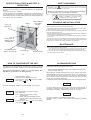
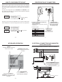
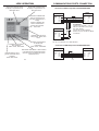
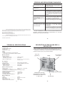
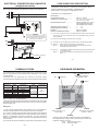
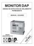
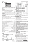
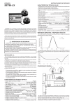
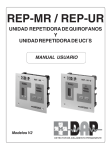
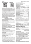
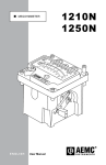
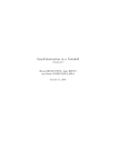
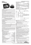
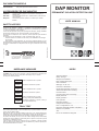
DAP MONITOR MODELS DAP II MONITOR DAP III MONITOR Single phase permanent isolation detector. Three phase permanent isolation detector. DAP MONITOR ACCESSORIES FOR DAP MONITOR REP-M DAP REP-U DAP DAPsystem PERMANENT ISOLATION DETECTION UNIT Terminal repeating signals of a DAP Monitor with display of isolation level. Terminal repeating alarms up to 10 DAP Monitors, with two wires communication. Control and supervision system for a network up to 32 DAP Monitors. USER MANUAL SAFETY NOTICES AFEI Sistemas y Automatización, S.A. Provença, 533 Local A - 08025 BARCELONA(Spain) Tel. (34) 93 446 30 50 - Fax (34) 93 446 30 51 http://www.afeisa.es email: [email protected] IMPEDANCE MEASURE To initiate the impedance measure of the installation, press the keys <VALIDAR> and <CLAXON> for 5 seconds. From this time, it will be measuring the impedance, the display of the intensity level in each phase will change every 7 seconds. The sequence will be as follows: F_r Start of impedance test in R phase. 0000 F_S 0000 Impedance measured in R phase. Start of impedance test in S phase. Impedance measured in S phase. Start of impedance test in T phase. (if being a three-phase DAP Monitor). F_t 0000 Impedance measured in T phase. (if being a three-phase DAP Monitor). TRIAL TEST With the TEST key of DAP Monitor, you can perform a system test during 5 seconds, then finishing automatically. If the «CLAXON» key is pressed before 5 seconds occurs, the test will then finish. Said test will cause an equivalent leakage higher than 5 mA, without affecting the impedance of the grounded system. If same works correctly, the Test led will light on and the alarm buzzer will be activated, but the alarm red led will not be lighted. The buzzer will actuate just as if it were an isolation leakage alarm, automatically stopping when the test finishes or else waiting for the operator to stop same (consult point «How to configurate the unit»). If the test starts by pressing the relevant key from a repeater, it will then actuate same way, lighting on the Test led, and if the «CLAXON» key of same is pressed, the test will also finish before 5 seconds. - 24 - Design and printed in Spain Cod. MUI750301040909-0 This unit has been designed according to rules UNE 20615(78), UNE 206151erC(80) UNE 206152onC.(85), EN60601-1, EN60601-1-1, EN60601-1-2 (includes EN 55011 and EN 61000-4-2 , EN 61000-4-2, EN 61000-4-3, EN 61000-4-4, EN 61000-4-5), EN 606011-4 and it is supplied in good conditions. Correct and safe operation of this product presupposes transport, storage, installation and mounting according to the rules as described in this User Manual. The unit does not dispose of fuse. Therefore, relevant protection parts should be envisaged. It is necessary to take precautions in order to increase safety, such as: - Functions that are not relevant for the safety of the installation are managed electronically. - Such functions whose breakdown may cause large material damages or even personal damages, are made using conventional control elements (electromechanical). The above considerations are independent from the type, manufacturer and country of origin. PERMANENT ISOLATION DETECTOR INDEX - Technical features................................................ - Safety warnings................................................... - Storage and installation......................................... - DAP operating description..................................... - Alarm indications................................................... - Starting-up of the unit............................................ - Connectors identification....................................... - Single-Phase Electrical Connecting....................... - Three-Phase Electrical Connecting....................... - Communications.................................................... - Communications Ports Connecting........................ - Display elements................................................... - Display operation.................................................. - Leds operation...................................................... - Keyboard operation.............................................. - Configuration Description..................................... - How to configurate the unit.................................. - Description of REP-M and REP-U Repeaters........ - Measure of impedance......................................... - Test....................................................................... - Errors and breakdowns diagnosis....................... 2 3 3 4 5 6 7 8 9 10 11 13 13 14 15 17 18 22 24 24 25 DESCRIPTION OF REP-M AND REP- U REPEATERS SAFETY WARNINGS Electric supply for the repeaters is given by the own DAP Monitor at 12 Vcc, thus it is not necessary to connect the repeaters to the equipotential network. There are two types of repeaters: - REP-M repeater is an unit designed to work with one only DAP Monitor, to carry out all functions in a remote way. It disposes of a leds bar to indicate the isolation level which the DAP Monitor is measuring, alarm indication led, horn stop key, key and test indicator. WARNING: Symbol means that there is a risk for the user, so information concerned should be looked for in the manual. Buzzer «On» Led (Operation) Alarm indicator Led of DAP Monitor Whatever use of the equipment in any way not specified by the manufacturer can endanger safety of the unit and affect user protection. Handling or installation of the unit must be made disconnected from the network. STORAGE AND INSTALLATION It is recommended to store the unit together with its respective packing box, having in mind climatic conditions as pointed out at item: Technical Features. This unit does not dispose of switch and fuse, therefore a magnetothermic switch should be installed, with a distance between open contacts higher than 3 mm. Previous works for installation purposes are not required, only take care of the relevant drill hole in the cabinet to place the unit. When placing the unit, should be noted the minimum dimensions concerning ventilation and connection of the wires of the inputs/outputs of the unit. For the connections to the unit terminals, it is recommended to use a cable having maximum section of 2 mm. Referring to the cables to be connected in the unit terminals, they should be secured to each other using a nylon clamp or similar, so that in case any cable releases from a terminal, there should not be any accidental contact either with earth or other equipments. Indicator bar of isolation level of DAP Monitor MAINTENANCE Led indicating DAP Monitor in test mode Test start key Buzzer stop key DAP Monitor does not require any Kind of special maintenance. Items to bear in mind when making revisions: - A test of the unit can be made (Trial Test), please refer to page 24 of this manual. - Check the state of cables, rivetted terminals and tightened couple of the terminals. To clean front side, just use a slighty damped cleaning cloth (not wet) with water and neutral soap, but not with an abrasive cleaner. - 22- -3- HOW TO CONFIGURATE THE UNIT ALARM INDICATIONS After having or not configurated the connection of a repeater, you should configurate the DAP Monitor number for communication with DAPsystem. Check that the DAP Monitor number is not configurated in other DAP Monitor connected in the DAPsystem PC. nP01 Enter DAP Monitor number. Number should be between 01 and 99. To change value, press < > key and to validate same, press < > key. DAP Monitor indicates the following alarm types: - Isolation leakage detection according to the programmed order value. - Earth-interruption detection. When detection of isolation leakage occurs, then an acoustic alarm will be released (buzzer) and a luminous one as well (Alarm Led). Acoustic alarm can be silenced by pressing the buzzer Key if same is programmed in manual mode. If buzzer is programmed in automatic mode, then it will finish ringing when the leakage disappears. At the display will be shown the leakage value which is causing said alarm. 4. 4 5 Following configuration method for buzzer operation will be shown: If the unit detects lack of continuity at the ground-connecting-board, if previously connected the reference (REF) as per the scheme indicated in this manual, the following message will be shown in the display: cl-0 cl-1 Enter desired option for buzzer operation. They options are: cL-0 = Buzzer will stop when pressing <CLAXON> key. cL-1 = Buzzer will stop immediately after the intensity level has decreased below the fixed level. To change option, press < > key and to validate same, press < > key. - 20 - no_t This alarm prevails over the leakage detection alarm. Operation of the no_t alarm is the same as when detecting an isolation leakage. -5- HOW TO CONFIGURATE THE UNIT IDENTIFICATION OF CONNECTORS When the unit is given tension, the word DAP and the inner software version which the unit has are shown on display; following the isolation level will be indicated. Afterwards you can have access to the configuration of the unit. To enter in unit configuration, keys <CONSIGNA> and <MEDIDA> must be pressed at the same time for 5 seconds, then the request for password entry will be shown on display. P_0.0 Enter accessing password. By default it is 00. To change digit, key < > should be pressed, and to validate same press < > key. Following you will access the configuration menu, and the first data which will be requested to us will be the supply tension level to be programmed. 220 230 Enter installation tension. They are as follows: 220 = 220VAC tension. 230 = 230VAC tension. To change tension, press < validation press < > key. ELECTRICAL CONNECTION CONNECTOR: - PHASES CONNECTION - EARTH CONNECTION - GROUND CONNECTING BOARD CONTROL - ALARM INPUT COMMUNICATIONS CONNECTOR FOR REP-M AND REP-U REPEATERS (refer to point Connecting Communications Port) Terminals description: > key, and for Term. 1 2 3 4 5 6 7 COMMUNICATIONS Description CONNECTOR FOR R phase DAPsystem S phase (refer to point Connecting T phase Communications Port) Earth Ground Conn.Board Ref. ALARM Common ALARM - 18 - -7- KEYBOARD OPERATION ELECTRICAL CONNECTION DAP III MONITOR (three-phase model) MEDIDA Changes read-out of measuring scale from mA to KΩ ISOLATION TRANSFORMER ACCORDING TO UNE 20.615 STANDARD R CONSIGNA (Order Value) Shows programmed order value on display. S T Ground connecting board IMPORTANT: In case not using ground connecting board control, terminal 5 (Ref.) should be bridged with terminal 4 (E), by means of a bridge in the proper connector of the Monitor. R S T When pressing CLAXON + VALIDAR at the same time, we will then check installation impedance. When pressing MEDIDA + CONSIGNA at the same time, we will enter into configuration menu of the unit. FAULT To terminal Ref. of DAP Monitor Ground connecting board - 16 - -9- LEDS OPERATION Shows that numerical value at display is expressed in kΩ. Red fixed colour. Shows that numerical value at display is expressed in mA . Red fixed colour. COMMUNICATIONS PORTS CONNECTION Connection of REP-U repeater with DAP MONITORS REP-U DAP Monitor Intermittent: Indicates that alarm is released just at the same time that horn is ringing. If fixed, it indicates that alarm is released and buzzer disconnected. Red colour. No. 1 TERMINALS GND Vcc A B (2) (1) (4) (3) (8) (9) (10) (11) DAP Monitor Indicates that trial test is being made. Yellow fixed colour. TERMINALS TERMINALS GND Vcc A B (8) (9) (10) (11) GND Vcc A B ATTENTION: Connect only terminal 1 (Vcc) of REP-U to terminal 9 (Vcc) of the first DAP Monitor. For the rest of DAP Monitors, terminal 9 (Vcc) should be without connection. No. n Indicates communication with repeaters. Yellow colour, intermittent. Indicates communication via RS485 with DAPsystem. Yellow colour, intermittent. No. Up to a maximum of 10 DAP Monitors Connection of REP-M repeater with DAP MONITOR REP-M DAP Monitor Indicates that the unit is ground connected and in operation. Green fixed colour. Will indicate that events or historic buffer is full and that the existing data will be removed in the next data to be saved. Red fixed colour. -14- TERMINALS TERMINALS GND Vcc A B (2) (1) (4) (3) (8) (9) (10) (11) - 11 - GND Vcc A B ERRORS AND BREAKDOWNS DIAGNOSIS Total or partial reproduction of this manual is not allowed, neither computerised use of same nor transmission in any way or through whatever mean, either electronic, mechanical, photocopy, register or other methods, without previous written approval by the owners of the Copyright. AFEI Sistemas y Automatización, S.A. Edition: AFEI Sistemas y Automatización, S.A. Printed: AFEI Sistemas y Automatización, S.A. LINE LED DOES NOT LIGHT. Check that the unit is correctly supplied in 1, 2 and/or 3 terminals. THE UNIT RE-STARTS CONSTANTLY. Supply tension can be too low. DISPLAY OF DAP MONITOR SHOWS ``no_t´´ Check that the furthest end of the ground connecting board has been connected to terminal 5 (Ref.), and ground to terminal 4 (E). If not using ground connecting board control, make a bridge with cable between terminals 5 and 4. DAP MONITOR DOES NOT HAVE COMMUNICATION OR DOES NOT WORK CORRECTLY WITH REP-M OR REP-U. Check wiring of the repeater. Check if it is active and type of REP used in the configuration of the DAP Monitor. In case of being long distances, place terminal resistances (consult page 10 of this manual). DAP MONITOR DOES NOT HAVE COMMUNICATION OR DOES NOT WORK CORRECTLY WITH THE DAPSYSTEM. Check RS485 communication cable. Check that the corresponding repeater is configurated at the DAP Monitor configuration. In case of being long distances, place terminal resistances (consult page 10 of this manual). Please refer to DAPsystem program manual. In case of breakdown or failure, the unit should be delivered to the distributor or directly to AFEI Sistemas y Automatización, S.A. to be duly repaired by the technical service dept. Information contained in this manual can be subjected to changes without previous notice and in no case represents an undertaking by the seller´s side. First edition: September 2.004 - 25 - TECHNICAL SPECIFICATIONS Internal: - Real time clock. - 4-digits numerical display. - 8 display Leds. - Keyboard with 7 Keys. - Buzzer. - Battery. - 1 RS485 communication port for DAPsystem. - 1 communication port for REP-M or REP-U repeaters. DESCRIPTION OF REP-M AND REP- U REPEATERS REP-U repeater is an unit designed to work with a maximum of 10 DAP Monitors, for the indication of the unit which has detected an alarm. It disposes of a leds bar to show the DAP Monitor number in alarm condition, buzzer stop key, key and test indicator. «On» Led (operation) Measure parameters: Buzzer - Isolation resistance: Measuring range in KΩ........................... 40 kΩ to 1100 kΩ Measuring range in mA........................... 0 to 5.00mA - Values of leakage alarm............................0.4, 0.8, 1.2, 1.6, 2.0, 2.4, 2.8, 3.2, 3.6 and 4.0 mA Led indicating test mode Inner Registers: - Inner registers:.................................. - Registers storage: ............................ - Registers capacity: Alarms and Events ......................... Historic registers ............................ Alarms, Events and Historic. 8 Kbytes EEPROM, cyclic mode. 500 registers. 500 registers. Electrics and environmental: - Supply tension ............................... 220-230 VAC +/- 20%, 50Hz. - Consumption at 230 VAC (*)............... 3,5 VA. - Inner isolation A.C. of 11MΩ with maximum own leakage of 20 µA. - Measuring tension less than 6V D.C. - Operation temperature ...................... 10ºC to 40ºC. - Storage temperature .................. -55ºC to 125ºC. - Transport temperature ...................... -20ºC to 60ºC. - Air humidity (without condensation) .... 60 %. Weight and Measures: - Weight ........................................... - Dimensions ................................... - Front Depth ................................... - Minimum panel depth ...................... - Cabinet drill hole for DAP Monitor ..... 1270 gr. DIN box 144 x 144 mm. 8 mm. 110 mm. 138 x 138mm. - 2- Indicating bar showing DAP Monitor number which has detected an alarm or is in test mode Buzzer stop key Test start key - 23 - OPERATION OF DAP MONITOR - DESCRIPTION DAP Monitor is a unit which measures the isolation resistance between any input phase and ground (earth). Supply of the unit is made through the same terminals through the isolation measure is carried out. The user will program a consign (value) of leakage current, which will be used by the unit to compare same with the instantaneous value which is being measured, and in case that the measured value exceeds this limit, it will then show an alarm. The unit will also detect alarm of earth-interruption if you connect at E input the initial end of the ground-connecting-board and the final end of that in Ref. input. By doing so, you will be measuring earth continuity, and if due to whatever reason said continuity would be interrumpted at any point of the ground-connecting-board, then an alarm would be produced. You can make a test of all the installation at any time through the TEST key. The unit will cause a leakage equivalent higher than 5 mA without affecting the impedance of the installation. Furthermore you can measure the existing impedance in the installation by pressing two keys. DAP Monitor has been designed to work in conjunction with other remote unit which can be a Repeater REP-M (operating theatre repeater) or Repeater REP-U (ICU repeater) which will display some parameters of the measuring unit state. Communication will be made through a two wires cable. DAP Monitor will store in EEPROM all alarms, events and historic registers which are generated in the installation, in order to be processed by means of the DAPsystem program through the RS485 communications port. From DAPsystem program you will also be able to change the units configuration and supervise the installation state, as well as reading the registers, events and alarms which the units have generated in the installation. HOW TO CONFIGURATE THE UNIT Following there will be shown the possibility of temporary establishing communications parameters by default: C.96..0 C.96..1 They options are: C.96.0 = Configuration of RS485 communications port is as programmed by the DAPsystem. C.96.1 = RS485 communications port configuration becomes: Bauds 9600 Parity No Bit Lenght 8 Stop Bits 1 When the unit is switched off and on again, it will restore the configuration programmed by the DAPsystem again. To change option, press < > key, and to validate same, press < > key. When pressing < > key after this last parameter configurated, leave programming mode and the unit is then ready to work. NOTE: In case that DAP Monitor is for more than 30 seconds in the configuration menu without a key being pressed, it will then quit the menu, moving to normal working state. Furthermore if a non operative key is pressed inside the configuration, then it will quit in order to avoid bad manipulations. When you leave the configuration menu, either due to time or by an uncorrect key stroke, the modified values will not be saved, therefore the previous values will be restored. -21- -4- STARTING UP OF THE UNIT HOW TO CONFIGURATE THE UNIT Starting up of DAP Monitor is made by means of the DAPsystem program; in case of not disposing of it, then it will be made throught the keyboard of the unit itself. Following the leakage current order value for alarm indication will be shown (please refer to point «Configuration description»). GIVE TENSION Initializing sequence (dap,1.4.....) to UNIT CONFIGURATION PROGRAMMING PARAMETERS OF DAP MONITOR CONFIGURATE UNIT PARAMETERS - UNIT CONFIGURATION OK? 00. 4 0 - Select supply tension: - 220VAC or 230VAC. Select order value: - 0,4 to 4,0 mA. Select repeater type: - REP - without repeater. - REP 0 Operating theatre repeater(REP-M). - REP u ICU repeater (REP-U). Select DAP Monitor number (for REP-U): - From 1 to 10. Select peripheral number of DAPMonitor: - From 1 to 32. Select horn mode: - Manual or Automatic. Enter desired value for leakage level detection. Values are as follows: 0.4, 0.8, 1.2, 1.6, 2.0, 2.4, 2.8, 3.2, 3.6, 4.0mA. To change value, press < > key and to validate same press < > key. 04. 0 0 After that, the option where you will configurate whether you connect a repeater or not will be shown (consult «Configuration description»). rEPrEP0 rEPu Enter desired option. They are as follows: rEP- = No repeater is connected. rEP0 = a REP-M repeater is connected. rEPu = it is connected to a REP-U repeater*. To change value, press < > key, and to validate press < > key. READY FOR OPERATION Default communications parameters are: 9600 bauds NO parity 8 bits length 1 stop bit Peripheral No: 99 TO GET THE UNIT HAVING DEFAULT CONFIGURATION, PLEASE REFER TO POINT «CONFIGURATION DESCRIPTION» IN THIS USER MANUAL. -6- * In case of configurating rEPu option, once previous action has been validated, you will be asked for the identification number of DAP Monitor for the REP-U repeater. Make sure that the identification number is not configurated in other DAP Monitor connected in the same REP-U repeater. nu01 Enter identification number. Number must be between 01 and 10. To change value, press < > key and validate by pressing < > key. - 19 - ELECTRICAL CONNECTION DAP II MONITOR (single-phase model) ISOLATION TRANSFORMER ACCORDING TO UNE 20.615 STANDARD R CONFIGURATION DESCRIPTION - Configuration of DAP Monitor is made by the same keyboard, when pressing simultaneously the MEDIDA + CONSIGNA keys. (please refer to point «How to configurate the unit»). - Parameters to be configurated are: S PASSWORD (1) ................................. TENSION SELECTION ....................... ORDER VALUE SELECTION ............. : : : REPEATER SELECTION (2) ................. : IDENTIFICATION FOR REP-U (3)......... NUMBER OF DAP MONITOR ........... BUZZER (4) ...................................... DEFAULT COMMUNICATIONS (5) ..... : : : : S -220Vca / 230Vca 0.4 / 0.8 / 1.2 / 1.6 / 2.0 / 2.4 / 2.8 / 3.2 / 3.6 / 4.0mA. Without repeater Rep - (rEP-) With repeater Rep-M (rEP0) With repeater Rep-U (rEPu) 1 ... 10 1 ... 32 Option 0 / Option 1 Option 0 / Option 1 Ground connecting board IMPORTANT: In case not using ground connecting board control, terminal 5 (Ref.) should be bridged with terminal 4 (E), by means of a bridge in the proper connector of the Monitor. R (1) Can only be programmed by PC. (consult DAPsystem manual). If this option has been selected, you will not able to enter into unit configuration unless you enter correct password. (2) Option to select repeater type wanted to be connected. (3) This option is only accesible when previous option is configurated as REP-U. S (4) Option 0 = Option 1 = Buzzer will stop when pressing <CLAXON> key. Buzzer will stop just immediately after the intensity level has decreased below the fixed level. (5) Option 0 = Configuration of RS485 communications port are just as programmed by the DAPsystem. Configuration of RS485 communications port becomes: 9600, NO, 8, 1. FAULT Option 1 = To terminal Ref. of DAP Monitor Ground connecting board -8- - 17- COMMUNICATIONS KEYBOARD OPERATION - The unit disposes of a RS485 communications port, and other one of two wires for communication with repeaters REP-M and REP-U, both of them are optoisolated. - Following we are describing the connector terminals where communications port RS485 and two-wires communication port are located: key (Advance) Key (ENTER) allows to validate data showed in configuration mode Buzzer Terminal nº 8 9 10 11 12 13 14 COMMUNICATIONS connector connections Signal Cable Description Input/Output Section (mm) GND 0,25 or 0,50 GND REP-M Vcc out 0,25 or 0,50 Supply o A 0,25 or 0,50 A Signal REP-U B 0,25 or 0,50 B SIgnal GND 0,25 or 0,50 GND TR0,25 or 0,50 DAPsystem Signal TxRx TR+ 0,25 or 0,50 Signal TxRx + Type of cable for communications - The recommended communication cable type should be minimum 2 couple with shielding (mesh) and with a section 0,25 or 0,50 mm, both for repeaters and DAPsystem port. DAPsystem - In long and high speed RS485 communication lines it is suggested to connect terminal resistances at the beginning and end of said lines. So, in case of working with DAPsystem with the RS485 communications port (TR-/TR+) of the DAP Monitor, if the distance between the PC and DAP Monitor is considerable, should be connected a 120 ohms resistance between TR- (Terminal 13) and TR+ (Terminal 14) at the DAP Monitor which is most remote. To connect the PC terminal resistance, please refer to DAPsystem manual. - 10 - CLAXON Disconnects the buzzer when it is active PRUEBA Allows carrying out a system test VALIDAR Said key will be pressed to validate the state of the installation, then registering the isolation level of same and time in which this happened. Display will show: ConF There is NOT any alarm. ALAr There is an alarm. - 15 - COMMUNICATIONS PORTS CONNECTION DAPsystem connection (RS485) DISPLAY ELEMENTS OF DAP UNIT 7 segments Display Leds indicating scale in which the value is showed in display. DAP Monitor TERMINALS GND TRTR+ (12) (13) (14) No. 1 Leds group showing Alarm or Test. DAP Monitor TERMINALS GND TRTR+ (12) (13) (14) Leds group indicating: line connection, if repeaters are connected, if there is communication with DAPsystem (RX/TX) and Buffer state. (5)* (3)* (2)* DISPLAY OPERATION No. No. Up to a maximum of 32 units (please refer to information DAPsystem.) * Indication of RS485 connector terminals of CRS-485. IMPORTANT NOTE: Recommended communication cable type for connection between DAP Monitors and also connection of same to the PC, should be min. 2 couples with shielding (mesh) with a section of 0,25 or 0,50 mm. (special cable for data communications). - 12 - DAP unit disposes of a 4-digits display of 7 segments each one, in which certain informations such as: unit version, leakage value etc. are shown. Display Description dAP dAP Alphabetical characters 1.3 1.3 Digits version. 3,18 03.18 Digits with decimals. - 13 -