1
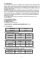
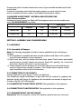
6 Burner Gas Range This appliance must be installed by a competent person in compliance with the installation and servicing instructions, and national regulations in force at the time. Particular attention must be paid to the following: Gas Safety (Installation & Use) Regulations. Health and Safety at Work Act. Adjustment must not be made by the user to parts which are protected by the manufacturer. Users of this appliance should be conversant with the appropriate provisions of the Fire Precautions Act and the requirements of the Gas Safety Regulations, in particular, the need to service the appliance on a regular basis to ensure the continued safe and efficient performance of the appliance. Always ensure that a competent person undertakes any servicing. This appliance must be earthed. After installation, the installer must ensure that the user is instructed on the safe use of this appliance, and has a copy of the user guide left with them for reference. This equipment is only for professional use, and should only be operated by qualified persons. It is the responsibility of the supervisor or equivalent to ensure that users wear suitable protective clothing and draw attention to the fact that, some parts will, by necessity become very hot and will cause burns if touched accidentally. If the appliance is fitted with castors, please take care to ensure that the front castors are locked when the appliance is in use. Take care when moving the appliance. When using the appliance: VAlways ensure that pan bases are dry, and flat before using them on the hob. VAlways position pans over the centre of the burner, and turn the handles to a safe position so they cannot be knocked or grabbed. VAlways use pans which are the correct size for this appliance (125mm - 420mm). V Always take care when removing food from the oven as the area around the cavity may be hot. V Always use oven gloves when handling any utensils which have been in the oven as they will be hot. VAlways make sure that the oven shelves are secured correctly. 1 Never use double pans, rimbased pans, old or misshapen pans, or any pan which is not stable on a flat surface. Never leave cooking fat, or oil, unattended. Never use the hob for any other purpose than cooking food. Plastic cooking utensils can melt if they come into contact with a warm hob. Never leave them close to, or on top of, the hob. Never leave the burner alight without a pan covering it. This causes a fire hazard. Do not place items on the door while it is open. Do not wrap foil around the oven shelves. Do not drape tea towels near the oven while it is on, this will cause a fire hazard. Do not use this appliance to heat anything other than food items, and do not use it for heating the room. Installation Clearances No shelf, overhang, cupboard, or cooker hood should be less than 1200mm above the pan supports, but please check this with the hood manufacturers instructions. The appliance must have a clearance of 100mm from any combustible material (wooden cabinets etc). At the rear, the appliance can be pushed back until the gas rail support bracket touches the wall. These appliances must be installed and serviced by a competent person as stipulated by the Gas Safety (Installation & Use) Regulations, IMPORTANT The installer must ensure that the installation of the appliance is in conformity with these instructions and National Regulations in force at the lime of installation. Particular attention MUST be paid to Gas Safety (Installation & Use) Regulations Health And Safety At Work Act etc. Local and National Building Regulations Fire Precautions Act Detailed recommendations are contained in Institute of Gas Engineers published documents :IGE/ UP/ 1, IGE/ UP/2 BS6173 and BSS5440 These appliances have been CE-marked on the basis of compliance with the Gas Appliance Directive for the Countries, Gas Types and Pressures as stated on the Data Plate. Pay particular attention in order not to disturb the air combustion admission or the combustion products evacuation of the appliance. WARNING - TO PREVENT SHOCKS, ALL APPLIANCES WHETHER GAS OR ELECTRIC, MUST BE EARTHED. On completion of the installation, these instructions should be left with the Engineerin-Charge for reference during servicing. After installation / service these Instructions should be handed over to the User, having had a demonstration of the operation and cleaning of the Appliance. 2 INSTALLATION AND SERVICE GUIDE IT IS MOST IMPORTANT THAT THESE INSTRUCTIONS BE CONSULTED BEFORE INSTALLING AND COMMISSIONING THIS APPLIANCE. FAILURE TO COMPLY WITH THE SPECIFIED PROCEDURES MAY RESULT IN DAMAGE OR THE NEED FOR A SERVICE CALL. PREVENTATIVE MAINTENANCE CONTRACT In order to obtain maximum performance from this unit we would recommend that a Maintenance Contract be arranged. Visits may then be made at agreed intervals to carry out adjustments and repairs. SECTION 1- INSTALLATION UNLESS OTHERWISE STATED, PARTS WHICH HAVE BEEN PROTECTED BY THE MANUFACTURER ARE NOT TO BE ADJUSTED BY THE INSTALLER. 1.1 SITING The appliance should be installed on a level, fireproof surface, in a well lit and draught free position. Should the floor be of combustible material, then local fire requirements should be checked to ensure compliance. There should be a minimum vertical clearance of 1200mm above the top of the pan supports. Important If the appliance is to be installed in suite formation with other matching appliances, the instructions for all models must be consulted to determine the necessary clearances to any combustible rear wall or overlying surface. Some appliances require greater clearances than others, and the largest figure quoted in the individual instructions will therefore determine the clearance of the complete suite adjoining appliances. The oven discharges vertically through the vent at the hob rear. There must be no direct connection of the flue to any mechanical extraction system or the outside air. Hotplate burners discharge combustion products directly into the room. Siting the appliance under a canopy is the ideal arrangement. Adequate ventilation, whether natural or mechanical, must be provided to supply sufficient fresh air for combustion and allow easy removal of combustion products which may be harmful to health. Recommendations for Ventilation of Catering Appliances are given in BS5440 : 2. For multiple installations the requirements for individual appliances should be added together. Installation should be made in accordance with local and/or national regulations applying at the time. A competent installer MUST be employed. 3 1.2 GAS SUPPLY The incoming service must be of sufficient size to supply full rate without excessive pressure drop. A gas meter is connected to the service pipe by the Gas Supplier. Any existing meter should be checked by the Gas Supplier to ensure that the meter is of adequate capacity to pass the required rate of the appliance in addition to any other gas equipment installed. Installation pipe work should be fitted in accordance with ICE/UP/2. The pipe work should be of adequate size but not smaller than the gas inlet connection on the appliance, i.e. Rp 3/4"B.S.P. An isolating cock must be located close to the appliance to allow shut-down during an emergency or servicing of the gas supply tubing shall comply with the national requirements in force and shall be periodically examined and replaced as necessary. The installation must be tested for gas tightness. Details of this procedure can be found in IGE/UP/1. 1.3 ELECTRICAL SUPPLY Not applicable to this appliance. 1.4 WATER SUPPLY Not applicable on this appliance. 1.5 HEAT INPUTS - NATURAL AND PROPANE GAS (kW net) 1.7.1 Total inputs Natural Gas 45.6 kW Propane Gas 41.4 kW 1.5.1 Individual inputs (kW net) Hotplate Oven Natural Gas 6.1 kW 9.0 kW Propane Gas 5.4 kW 9.0 kW 1.6 INJECTOR DIAMETERS -NATURAL AND PROPANE GAS Hotplate Oven Natural Gas 193 240 Propane Gas 120 155 1.7 GAS PRESSURE ADJUSTMENT - NATURAL AND PROPANE GAS The following supply pressures apply to all units. Natural Gas 20 mbar 8” w.g Propane Gas 37 mbar 14.8” w.g 4 Pressure test point is located towards the centre of gas manifold situated behind front control facia. Connect a manometer and check that supply pressure is correct when the oven burner is ignited and then turned to the highest temperature setting. 1.8 BURNER ADJUSTMENT -NATURAL AND PROPANE GAS 1.8.1 Burner aeration Hotplate and oven burners are fitted with fixed bypass screws and set aeration apertures, NO ADJUSTMENT is possible. Heat inputs Hotplate Oven Hotplate Oven Natural Gas 84 94 1.15 kW 1.40 kW Propane Gas 50 64 0.95 kW 1.40 kW SECTION 2- ASSEMBLY AND COMMISSIONING 2.1 ASSEMBLY 2.1.1 Assembly of Ranges Note: The following paragraphs should be read as applicable to the unit being assembled. a) If the appliance is supplied with feet: Unpack appliance and place unit in position using the feet adjusters to level appliance. b) Open oven door, pull out shelves and loose base panel. Check burner spark igniter arrangement is correctly located and secured. Ensure ALL packing, etc. is removed from oven. Replace all parts in reverse sequence. c) Check hotplate, remove packing, etc. from hob area and ensure that all burners and pan supports are secured in position. The hotplate burner caps fit loosely upon aluminium skirts of lift-off construction. 2.2 CONNECTION TO GAS SUPPLY Connect appliance to gas supply. Test for gas tightness. The integral gas supply downstream of gas valve may be checked by applying leak detection spray with burner lit. Appliance inlet connection terminates at upper rear RH side in Rp3/4 (3/4" BSP female). 2.3 CONNECTION TO ELECTRICAL SUPPLY Not applicable to this appliance. 2.4 CONNECTION TO WATER SUPPLY Not applicable to this appliance. 2.5 COMMISSIONING THE APPLIANCE Important: Prior to operation, ensure ALL packing material has been removed. 5 2.5.1 Setting the gas pressure a) It is necessary to check the gas pressure during commissioning and a suitable pressure gauge must be connected to pressure test point towards the centre of the gas rail behind the fascia. b) Now turn on main gas valve at supply to unit. c) Ignite the oven burner on the unit as described in section 2.5.3. As gas supply pipes may contain air, continue to repeat lighting procedure until flame is established. Turn the control knob to the maximum temperature position and ensure supply pressure is correct. d) Disconnect pressure gauge from test point. Replace test point sealing screw and test for gas tightness. 2.5.2 Checking the performance of the controls a) Light hotplate or oven as detailed in Section 2.5.3. Check ignition is smooth and without delay. Repeat operation several times. b) Place a thermocouple in centre of oven and select 210°C on thermostat knob. Allow oven to heat up and check temperature is 210 +/- 15°C. If temperature reading is outside specified range, there may be a faulty thermostat, in which case the unit should be serviced (see thermostat replacement and calibration procedure). Turn OFF gas supply to oven and allow a sufficient cool down period before removing thermostat. 2.5.3 Lighting sequence Important: Prior to operation, ensure ALL packing material has been removed from appliance. Hotplate 1. Ensure mains gas is turned on. 2. To light hob burners, press knob and turn to full flame position. Ignite burners using taper or match. Hold in knob for 5 - 10 seconds and then release. Check burner remains lit and turn knob to required position. Oven 1. Ensure mains gas is turned on. 2. To light oven, open doors - press thermostat knob and turn anticlockwise to the ignition position. Push and hold in the thermostat knob. Press the piezo ignition button - adjacent to the thermostat knob - to provide a spark to the burner. 3. Having lit the burner, continue to hold thermostat knob in for a further 20 seconds before releasing. Check burner remains lit and turn thermostat to required setting. 4. To extinguish oven flame, turn thermostat to OFF position. 6 2.6 INSTRUCTION TO USER Whenever possible, the installer should ensure that the user thoroughly understands the instructions for lighting, cleaning and correct use of the appliance. It is also important to ensure that the location of the gas isolating cock is made known to the user, and that the procedure in an emergency is demonstrated. SECTION 3- SERVICING AND CONVERSION IMPORTANT: BEFORE ATTEMPTING ANY SERVICING, ENSURE ISOLATING COCK IS TURNED OFF AND CANNOT BE INADVERTENTLY TURNED ON. AFTER ANY MAINTENANCE TASK, CHECK APPLIANCE TO ENSURE THAT IT PERFORMS CORRECTLY AND CARRY OUT ANY NECESSARY ADJUSTMENTS AS DETAILED IN SECTION 1. After carrying out any servicing or exchange of gas carrying components ALWAYS CHECK FOR GAS TIGHTNESS! 3.1 REMOVAL OF CONTROL PANELS AND BURNERS Various panels are removed as follows:3.1.1 Removal of fascia panel First remove all control knobs Open oven doors and remove the two screws from the underside of the fascia panel. Remove the two screws at each end of the fascia panel Lastly remove the 3 fixing screws from the front of the fascia panel. Fascia panel can now be removed from the appliance. 3.1.2 Removal of the hotplate Remove all pan supports, burner caps and burner skirts. Using the front left hand and right hand burner apertures lift the front of the hotplate upwards to an angle of approximately 45 degrees and then pull the hotplate forward. The hotplate should now be free from the rear vent and can be removed from the appliance. 3.1.3 Replacement of hotplate burner (jet holder) Remove hotplate as detailed on the previous page. Disconnect the hotplate pipe from the chosen burner by undoing the compression nut at the burner. Remove the two fixing screws holding the hotplate burner in place. The burner can now be removed from the appliance. The new hotplate burner is to be fitted in the reverse order 7 3.1.4 Replacement of the oven burner Remove oven shelves, and oven base panel. Disconnect the oven burner pipe from the brass injector on the oven burner Disconnect the thermocouple from the oven burner Disconnect the electrode lead from the oven electrode Remove the four screws from the oven burner (note that the electrode bracket will also become free from the appliance by removing the burner fixing screws) The oven burner can now be replaced. To fit new oven burner the above sequence should be followed in reverse. 3.2 Cleaning Burners should be cleaned periodically to maintain maximum performance. Open top burners should be cleaned as detailed in User Instructions. Other burners are best cleaned with a wire brush; port blockage should be freed using a metal broach, any loose material being shaken out via the burner shank. 3.2 INJECTORS 3.2.1 Hotplate Remove burner caps and skirts. Undo and carefully remove injector. Replace in reverse order. 3.2.2 Oven Remove burner as detailed in ‘Replacement of the oven burner’ Undo injector and remove. Replace in reverse order. 3.4 THERMOCOUPLES AND FLAME FAILURE DEVICE (FFD) 3.4.1 Hotplate flame failure device magnet unit. To remove and replace FFD magnet unit, the following procedures must be followed, Undo thermocouple at FFD section of gas tap. Undo FFD section cap at rear of gas tap and withdraw magnet unit and replace in reverse order. 3.4.2 Hotplate thermocouple Remove hotplate as detailed in Section 3.1.2. Remove nut securing thermocouple sensor to burner support bracket and pull thermocouple through support bracket from underside. Undo thermocouple connection at FFD section of gas tap and carefully remove thermocouple. Replace in reverse order, take care not to overtighten thermocouple. 3.4.3 Oven flame failure device magnet unit Undo thermocouple connection at FFD section of thermostat. Undo FFD section cap at rear of thermostat and withdraw magnet unit. Replace in reverse order, take care not to overtighten thermocouple. 8 3.4.4 Oven thermocouple Remove hotplate as detailed in Section 3.1.2. Undo thermocouple connection at FFD section of thermostat. Open oven doors, remove shelves and oven base panel. Remove nut securing thermocouple sensor to burner bracket. Remove thermocouple from bracket. Pull remainder of thermocouple into oven, through hole in left hand oven side panel. Replace in reverse order and take care not to overtighten the connection at the thermostat rear. 3.5 OVEN IGNITERS AND ELECTRODES Igniter is piezo spark type and contains no batteries. Unit comprises piezo, housing, lead and electrode assembly. Lead is push-fit at piezo and electrode ends. Oven igniter electrode tip should be positioned 3.5mm from burner port. 3.5.1 Oven igniter Remove the fascia panel as detailed in Section 3.1.1. Disconnect earth wire and electrode lead from piezo housing. Remove nut holding igniter in place and remove igniter. 3.5.2 Oven electrode Remove oven shelves and base plate. Disconnect igniter lead from electrode. Undo M3 x 6 Torx head screw securing electrode to bracket. Remove electrode and replace in reverse order. Note Care should be taken not to damage the electrode. 3.6 OVEN THERMOSTAT Remove control knobs and fascia panel as detailed in Section 3.1.1. Remove hotplate as detailed in Section 3.1.2. Undo thermocouple connection at FFD section of thermostat. Disconnect the oven burner supply pipe at thermostat rear. From inside the oven, note the route/location of the thermostat capillary/phial. Gently pull the thermostat phial free from the left clip. Slide the phial to the left to free the phial’s clenched end from the right clip’s locator hole. Carefully feed capillary and phial through the oven top panel’s hole. Undo fixings which secure thermostat to gas rail. Replace all parts in reverse order, renewing o-ring seal if necessary. Take care not to overtighten thermocouple connection at thermostat rear. 3.6.1 Thermostat calibration The thermostat does not require calibration. If centre oven temperature is outside specified tolerances then replace thermostat and return faulty thermostat to the Customer Care Centre. 9 3.7 GAS TAPS Note: Plugs and bodies are machined in pairs and are, therefore, not interchangeable. Always clean one tap at a time. 3.7.1 Removal of gas taps Remove control knobs and fascia panel as detailed in Section 3.1.1. Remove hotplate as detailed in Sections 3.1.2. Undo thermocouple connection at FFD section of gas tap. Undo burner supply pipe at gas tap rear. Undo fixings which secure tap to gas rail. Replace all parts in reverse order, renewing o-ring seal if necessary. Take care not to overtighten thermocouple connection at gas tap rear. 3.8 FAULT CHECK LIST If a flame is not established on any burners (hotplate or oven), follow this check list 1. Check mains gas is ON. 2. Check pressure at pressure test point to ensure gas is flowing to the appliance. 3. If gas is present then check burner injector for blockage. 4. If injector is OK then check FFD magnet unit is engaging and allowing gas to pass. 5. OVEN ONLY - Check for spark at spark electrode. 6. OVEN ONLY -if there is no spark then check spark gap and igniter lead connections. Also check igniter. 7. If a flame is still not present then re-check from start. If a flame is established but not maintained then follow this check list. 1. Check thermocouple sensor is secured correctly and that burner ports are clean. 2. Check that thermocouple is not damaged and is securely fixed to FFD section of gas control. 3. Check FFD is energising and maintaining flame. 4. If after carrying out the above, the burner is still not maintaining the flame then check magnet unit within control. SECTION 4- SPARES When ordering spare parts, always quote the appliance type and serial number. This information will be found on the data badge attached on the rear of the product. 10 USER’S GUIDE SECTION 1 - ABOUT YOUR APPLIANCE All models are fitted with flame failure devices to shut off gas supply to burners if flames are extinguished. The oven is thermostatically controlled. All taps are the safety type with fixed HIGH and LOW settings. Hotplate controls Control knob makings are as indicated below Off High Low Oven thermostat The oven is thermostatically controlled. The control knob markings are in degrees celsius. Note: Spark ignition button is located on the facia, next to the thermostat control knob. These controls are identified by the symbols (shown below) which are on the facia. SECTION 2 LIGHTING AND OPERATIONS Hotplate 1 Press and turn knob to full flame position 2 Light burner using taper or match and continue to hold knob in for a further 5 - 10 seconds before release 3 Burner should remain lit but if burner goes out return to Step 1 and repeat ignition procedure 4 When burner remains lit, turn knob to required position 11 To turn the hotplate off, turn knob to OFF position Oven 1 Open oven doors * 2 Push in and turn thermostat knob to the ignition setting indicated with a ‘ ‘ and push and hold in the control knob to establish a flow of gas to oven burner 3 Continue to press knob in and at the same time, push piezo igniter button next to the oven thermostat control knob (see illustration on previous page) to provide a spark at oven burner 4 Having established burner flame, maintain pressure on knob for a further 5 - 10 seconds before release 5 Burner should remain lit. Should burner fail to remain lit, wait 3 minutes then return to Step 2 and repeat ignition procedure 6 When burner remains lit, turn thermostat to required position To turn the oven burner off, turn thermostat control knob to OFF position. Warning: The area around the oven will become very hot while the oven is in use. Take care when opening the oven doors. SECTION 3 COOKING HINTS Hotplate The pan supports will safely accommodate pans from 125mm diameter up to 420mm maximum. Note: For maximum efficiency, place pan centrally over burner head and adjust control setting to avoid flames licking up pan sides Shelves Two cooking shelves are supplied which can be supported in any of four different positions within the oven. When two shelves are being used , these should be positioned so that at least one single shelf space is left between them. Always push shelves into oven until the stops hit the rear of the supports Tray sizes A 900mm wide oven will accommodate a 2/1 Gastronorm tray. Single trays or dishes should be placed centrally. Trays must not be allowed to overhang the shelf in any direction as this will adversely affect heat circulation. In particular, NEVER allow a utensil to accommodate the space beyond the rear shelf upstand. Preheat time Allow at least 15 minutes from lighting a cold oven before a full load of food may be cooked. Put food in quickly and close the doors firmly 12 SECTION 4 CLEANING AND MAINTENANCE All surfaces are easier to clean if spillages are removed before they become burnt on and if units are cleaned daily Stainless steel surfaces These surfaces should be cleaned with hot water and detergent then dried and polished with a soft cloth Cleaning agents containing bleach, abrasives or caustic chemicals will damage or mark the stainless steel surfaces and must not be used. Vitreous enamel surfaces Approved cleaning agents which have the mark of the Vitreous Enamel Development Centre are recommended It is advisable to clean daily after use. Wipe clean the vitreous enamel surfaces while they are still warm using a soft cloth and hot soapy water. Badly stained, removable parts should be soaked in hot water with an approved detergent if the parts are not removable from the unit the application of warm water with approved detergent using nylon or scotch cleaning pads will give good results. Hotplate Burner cleaning should be carried out daily. Burner efficiency will be reduced significantly if recommended cleaning is not carried out. Remove pan supports and hotplate burner caps Wash all parts with hot soapy water according to detailed instructions enclosed at end of section. After washing, dry all parts well and ensure all water is removed from inside burner head. The hob may be lifted off for cleaning purposes. Using the front left hand and right hand burner apertures lift the front of the hotplate upwards to an angle of approximately 45˚ and then pull the hotplate forward. Re-fitting the hotplate: Rest hotplate on the top of the appliance at 45˚ and slide back until the rear flange is under the vent trim. Then lower the hotplate onto the side panels. Dry off the pan supports by hand. NEVER LEAVE THESE TO DRY NATURALLY. OVEN To clean the oven Clean while oven is warm but not hot. The enamelled base plate lifts out. The shelf guides can be removed by removing the four fixings. The oven base is removed by lifting at the front, and pulling towards you. 13 CLEANING INSTRUCTIONS FOR HOTPLATE BURNERS The following instructions should be followed when a) A spillage has occurred on the burner b) The burner fails to light or stay alight c) At the end of each day or cooking period Caution: Parts may be hot therefore protection to avoid burns should be used. 1 Remove pan support. 2 Remove burner cap and skirt by lifting upward. 3 Thoroughly clean with soap and water. Ensure all burner ports are clean and free from food or cleaning material debris Important: Stubborn debris lodged in ports can be removed using a non metal implement such as a cocktail stick. The base should be cleaned of debris using a soft brush. Dry burner caps with soft cloth and blow through the ports to ensure there is no blockage 4 Clean any spillage from burner skirts, ensuring all food and cleaning material debris is removed. Dry burner skirts thoroughly, taking care not to damage the flame sensor. Important: Do not allow any spillage or cleaning material debris to enter the large hole in the burner skirts. 5 Replace burner caps and skirts upon burner base and ensure the cap location fits within burner skirt notches. When burner head is properly located - it will not rotate. 6 Light burner to check that it operates correctly. Note: Ensure that all parts are dried thoroughly prior to relighting. Note: This process should be followed prior to calling for a Service Engineer. Failure due to lack of proper cleanings may result in work being charged for. 14 Spares List Part number Description Qty. 502989600 Bracket electrode support 1 082986600 Burner assembly 1 082982600 Burner cap assembly 6 082982500 Burner skirt 6 502991801 Oven door outer left hand side 1 502991900 Oven door outer right hand side 1 502991600 Door oven inner panel 082510900 Electrode oven 62C17437 DEL704 1 503016800 Fascia panel 1 081502200 Generator ignition piezo black 1 082744000 Handbook 1 082983500 Handle door 2 082982400 Holder jet 6 012980500 Hotplate assembly 1 082988100 Injector natural gas 1 082983800 Control knob (hotplate) 6 082983801 Control knob (oven) 1 080125000 Locknut thermocouple BRASS 7 082984000 Pan support 3 084367387 Screw M3X6 Torq pan head BZP 1 082993800 Seal oven 1 082986700 Shelf oven 2 502992900 Support tap rail rear 1 082821300 Thermocouple 1500mm 1 082980700 Thermocouple hotplate 6 082982200 Thermostat oven natural gas 1 082983601 Wheel (with brake) 2 082983600 Wheel (no brake) 2 082983900 Foot 4 2 08 27440 00 © 06.2009 15 CE371~N/P TELEPHONE HELPLINE: 0845 146 2887 (UNITED KINGDOM) Fourth Way, Avonmouth, Bristol, BS11 8TB 08 27440 00 © 06.2009 16