1
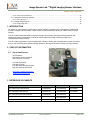
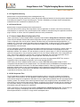
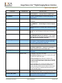
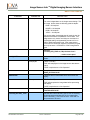
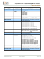
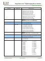
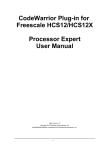
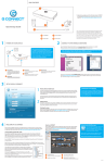
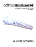
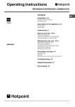
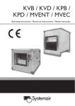
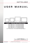
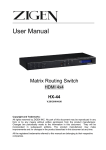
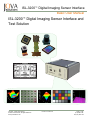
ISL-3200™ Digital Imaging Sensor Interface
Basic User Manual
ISL-3200™ Digital Imaging Sensor Interface and
Test Solution
TM
ISL-3200 Basic User Manual
© 2009 Jova Solutions, All Rights Reserved
www.jovasolutions.com
Doc No: 210-0001-07
Page 1 of 38
(415) 348.1400
fax (415) 348.1414
ISL-3200™ Digital Imaging Sensor Interface
Basic User Manual
Table of Contents
1. INTRODUCTION ........................................................................................................................................................3
2. CONTACT INFORMATION.......................................................................................................................................3
2.1 SALES AND SUPPORT .............................................................................................................................................3
3. REFERENCE DOCUMENTS ....................................................................................................................................3
4. GENERAL CONCEPTS ............................................................................................................................................4
5. ISL INSTALLATION ..................................................................................................................................................6
5.1 SOFTWARE INSTALLATION .......................................................................................................................................6
5.1.1 Starting the ISL Software Installation ...........................................................................................................6
5.2 ISL HARDWARE SETUP...........................................................................................................................................7
5.3 ISL HOST COMPUTER INTERFACE SETUP ...............................................................................................................7
5.3.1 External PCI Express Interface ....................................................................................................................7
5.3.1.1 External PCI Express Driver Installation................................................................................................................. 7
5.3.1.2 Connecting the ISL hardware to the host computer using External PCIe ............................................................ 7
5.3.2 USB 2.0 High Speed Interface .....................................................................................................................7
6. ISL APPLICATION SOFTWARE..............................................................................................................................8
6.1 ISL CONFIGURATION AND SUPPORT FILES .............................................................................................................8
6.1.1 isl_3010.bit .....................................................................................................................................................8
6.1.2 ISL.ini..............................................................................................................................................................8
6.1.3 Pdata.cfg ........................................................................................................................................................8
6.1.4 Decoding.cfg ..................................................................................................................................................8
6.1.5 PluginDecoders.cfg .......................................................................................................................................9
6.1.6 Recent files.ini ...............................................................................................................................................9
6.1.7 Sensor Adapter Board Configuration Files ..................................................................................................9
6.1.8 ISL Sequence Files .......................................................................................................................................9
6.2 RUNNING THE ISL APPLICATION SOFTWARE .........................................................................................................10
6.2.1 ISL Menus ....................................................................................................................................................11
6.2.2 File Menu .....................................................................................................................................................11
6.2.3 Device Menu ................................................................................................................................................12
6.2.3.1 ISL System Submenu ............................................................................................................................................ 12
6.2.3.2 ISL Power Supplies Submenu............................................................................................................................... 13
6.2.3.3 PS-IO Tab of the ISL-3200 Power Supply Control Panel .................................................................................... 14
6.2.3.4 PS-A, PS-B, PS-C, PS-D Tab of the ISL-3200 Power Supply Control Panel..................................................... 14
6.2.3.5 PS-E, PS-F, PS-G, PS-H and PS-U Tabs of the ISL-3200 Power Supply Control Panel ................................. 15
6.2.3.6 Adapter Tab of the ISL-3200 Power Supply Control Panel ................................................................................. 15
6.2.3.7 Status LED Control Tab of the ISL-3200 Power Supply Control Panel .............................................................. 15
6.2.3.8 ISL Reference Clock Submenu............................................................................................................................. 15
6.2.3.9 ISL Digital I/O Submenu ........................................................................................................................................ 16
6.2.4 ISL Sensor Adapter Menu ..........................................................................................................................17
6.2.4.1 ISL Sensor Communication (I2C) ......................................................................................................................... 17
6.2.5 Capture Menu ..............................................................................................................................................19
6.2.5.1 Image Capture Settings Control Panel ................................................................................................................. 19
6.2.6 Tools Menu ..................................................................................................................................................23
ISL-3200
TM
Basic User Manual
Doc No: 210-0001-07
Page 2 of 38
Image Sensor Lab TM Digital Imaging Sensor Interface
Basic User Manual
6.2.6.1 Event Counter Submenu ....................................................................................................................................... 23
6.2.7 Sequence Scripting Submenu ....................................................................................................................24
6.2.7.1 F Key Shortcuts...................................................................................................................................................... 38
6.2.8 Image Analysis Menu ..................................................................................................................................38
6.2.8.1 Image Pixel Data.................................................................................................................................................... 38
1. INTRODUCTION
ISL-3200™ is a cost-effective combination of sensor interface, test electronics and application software that
provides complete communications, image capture, and characterization testing, of a wide variety of image
sensors.
The ISL software application offers scripting and plug-in functionality, allowing enhanced graphical user
interfaces to specific image sensor models as well as customized image processing analysis and
characterization testing routines.
The ISL software application is pre-configured with a library of testing and characterization routines, as well as
many of the processing tools that are typically needed for thorough evaluation and testing of image sensors.
2. CONTACT INFORMATION
2.1
SALES AND SUPPORT
Jova Solutions
965 Mission Street, Suite 600
San Francisco, CA 94103
415-348-1400 Office
415-348-1414 Fax
415-348-1408 Technical Support
800-755-1400 Toll Free Sales
http://www.imagesensorlab.com
[email protected]
3. REFERENCE DOCUMENTS
Description
Doc. No
Company/Author
Rev. Date
ISL-3200 Product Specification
210-0004-08
Jova Solutions
07/14/2009
ISL-3200 Basic User Manual
210-0001-01
Jova Solutions
07/14/2009
ISL-3200 Advanced Analysis Guide
210-0002-01
Jova Solutions
07/14/2009
ISL-3200 Quick Start Guide
210-0008-02
Jova Solutions
07/14/2009
ISL-3200 Test and Automation Suite Guide
210-0003-01
Jova Solutions
07/14/2009
ISL-3200 Basic User Manual
Doc No: 210-0001-07
Page 3 of 38
ISL-3200™ Digital Imaging Sensor Interface
Basic User Manual
4. GENERAL CONCEPTS
ISL-3200 consists of application software running on a host computer, which communicates with the ISL
hardware. Users connect image sensors to the I/O connector on the ISL hardware and use the application
software to control the ISL hardware to communicate with and acquire images from the image sensor. The ISL
hardware contains all the system components needed to interface many different CMOS image sensors.
The ISL application software provides flexible image capture, display and analysis capabilities and also provides
a set of productivity tools that ease the process of communicating with and testing image sensors. The
application software provides full Bayer image support and includes a variety of built-in Bayer decoding and
interpolation options. Image Sensor Lab uses four basic image buffer types for Raw, Bayer, RGB, and YCbCr
(YUV) image types.
The Image Sensor Lab application software also provides several image analysis and characterization test
panels including uniformity, defective pixels, Bayer analysis, dust and particles, focus accuracy, SFR/MTF
analysis, and Macbeth color accuracy tests.
The ISL application software also provides a sequencing engine, including application scripting with which users
can automate tedious startup configuration or mode changing steps. The ISL hardware, I2C sensor
communications, and the ISL application software can all be controlled by simple text sequence files.
A plug-in architecture is included that allows users to write their own display and analysis panels, using the
LabVIEW development package from National Instrument (http://www.ni.com).
Timer/Counter measurements are also available on all image sensor connections and can be run in parallel with
image sensor communications and image capture.
ISL Instrument
Sensor I2C and SPI
Communications
ISL Software Packages
ISL
Basic
ISL
Advanced Analysis
Embedded 0-4VDC
Power Supplies
16-bit Wide Image
Data Capture
ROI Capture
Master Clock Source
up to 136 MHz
32 MByte Capture
Memory
Video Rate
Sequential Capture
Digital I/O
Flexible Decoding
Options
Timer/Counter
Digital Image Capture
RAW, Bayer, RGB
and YCbCr (YVU)
Scripting and
Sequencing Engine
Field Upgradeable
FPGA
Full Bayer Support
Raw Data & Bit
Histogram
ISL-3200
TM
Basic User Manual
ISL
Test & Automation
Light and Dark
Field
Color Accuracy
Automation API
Uniformity
SMIA Tests
LabVIEW Drivers
Defective Pixels
Dynamic Range
TestStand Step Types
Dust and Particles
Fixed Pattern Noise
Pre-written Automated
Tests
Focus Accuracy
Temporal Noise
Application Plug-ins
SFR/MTF Analysis
Dark Signal
Application Scripting
Doc No: 210-0001-07
Page 4 of 38
ISL-3200™ Digital Imaging Sensor Interface
Basic User Manual
The ISL-3200 application software runs on a host computer and connects, through a single USB 2.0 High Speed
cable, to the ISL image sensor interface electronics box. (PCI Express connection is an available option.) The
ISL hardware contains all the components needed to interface a variety of CMOS image sensors. Power
supplies, I2C communications, digital image capture, and additional I/O are contained within the box and are
accessed through the 64-pin I/O connector. (See figure below).
Host Computer
ISL-3200 Interface Electronics
Image Sensor Lab
Application Software
I2C Communications
CMOS Image Sensor
0 - 4VDC Power Supplies
Digital I/O
USB
USB
Digital Image Capture
Image sensor adapter boards plug into the two 160-pin connectors on the ISL hardware, as shown in the image
below. These adapter boards are specific to the connector type used to mount the image sensor under test and
route the ISL unit signals, available through the two 160-pin connectors, to the appropriate pins of the image
sensor connector on the adapter board.
Customer-specific Adapter Board
ISL-3200
TM
Basic User Manual
Doc No: 210-0001-07
Page 5 of 38
Image Sensor Lab TM Digital Imaging Sensor Interface
Basic User Manual
Typical CMOS Camera Modules Used with Image Sensor Lab
5. ISL INSTALLATION
Before attempting to plug in and operate the ISL software and ISL hardware, follow the installation instructions
below, which ensure proper installation and configuration of the various components that comprise the Image
Sensor Lab product. The software must be installed prior to connecting the USB cable so that the needed
software components are available when the Windows operating system detects the new hardware.
5.1
SOFTWARE INSTALLATION
The Image Sensor Lab product contains several software components that are automatically placed on your hard
disk during the installation procedure.
A. The Image Sensor Lab Application Software (ImagesSensorLab.exe)
B. Low-level USB or PCIe Drivers
C. National Instruments IMAQ Libraries
5.1.1 Starting the ISL Software Installation
Place the ISL™ software installation CD into the host computer CD drive and run the Install.exe.
Follow the prompts to fully install all software components. The installer creates an ISL directory in the
C:\Program Files directory and installs low-level USB or PCIe drivers in the Windows directory.
ISL-3200 Basic User Manual
Doc No: 210-0001-07
Page 6 of 38
Image Sensor Lab TM Digital Imaging Sensor Interface
Basic User Manual
5.2
ISL HARDWARE SETUP
First ensure that an image sensor is connected to the ISL unit.
Although this documentation references the demo adapter
Micron 1.3 Megapixel image sensor, the instructions are similar,
regardless of sensor type. Be sure that the image sensor is
properly mounted and connected.
The sensor connection to the ISL-3200 is through the two 160pin high density connectors on the top of the ISL-3200 unit.
5.3
ISL HOST COMPUTER INTERFACE SETUP
The ISL hardware contains either a USB 2.0 High Speed interface, or an External PCI Express interface. Refer to
the Sections 5.3.1 and 5.3.2 for details specific to each interface.
5.3.1 External PCI Express Interface
5.3.1.1
External PCI Express Driver Installation
Refer to the Image Sensor Lab Getting Started Guide for PCIe driver installation
details.
Install the ISL PCIe driver before connecting the ISL hardware to the computer.
The PCIe driver requires the NI-VISA subsystem. The Image Sensor Lab
Installer installs the NI-VISA subsystem. Ensure the NI-VISA subsystem is
correctly installed on the host computer before installing the ISL PCIe drivers.
The Image Sensor Lab installer also installs the PCIe driver .inf file. This file is
located in C:\Program Files\Image Sensor Lab\Drivers\Jova External PCIe.inf,
and you may be prompted by the operating system for the location of the .inf
file.
5.3.1.2 Connecting the ISL hardware to the host computer using
External PCIe
Power-down both the host computer and the ISL hardware. Once power is
disconnected, insert the PCIe express card into the laptop express slot, or if
using a workstation computer install the PCIe adapter card. Connect the ISL
hardware to the host computer using the provided External PCIe cable.
Once the cable is securely connected to both the ISL hardware, the host computer adapter power may be
applied, first to the ISL hardware and then to the host computer.
NOTE: Once the host computer has booted up, the power to the ISL hardware must not be interrupted. If the
power to the ISL hardware is removed, you must shut down the host computer completely before re-applying
power to the ISL hardware.
5.3.2 USB 2.0 High Speed Interface
Attach a USB 2.0 High Speed cable between the ISL HARDWARE and the Host Computer. Be sure to use a root
hub on the host computer. DO NOT use an un-powered external USB hub! For optimal performance, choose a
root hub with the least number of additional devices connected.
The Windows operating system will detect a new device and prompt the user with a “found new hardware”
dialog. Follow the prompts to finish installing the USB device drivers.
ISL-3200 Basic User Manual
Doc No: 210-0001-07
Page 7 of 38
Image Sensor Lab TM Digital Imaging Sensor Interface
Basic User Manual
6. ISL APPLICATION SOFTWARE
Image Sensor Lab application software is a Windows–based application, which provides a Graphical User
Interface (GUI) that you will use to control the ISL Image Sensor Interface electronics and to acquire, display,
and process images. Image Sensor Lab is installed in the C:\Program Files\Image Sensor Lab directory by
default.
6.1
ISL CONFIGURATION AND SUPPORT FILES
Before you run the ISL application software, a short introduction to the various configuration files used by the
application is appropriate. There are several configuration files that can be used to quickly change the behavior
of the ISL hardware and the ISL application software. These configuration files can be used to rapidly switch from
one image sensor type to another, which may have completely different power supply, digital I/O, frame capture
or sensor interface board requirements.
The following configuration files are created during the installation process and are required for the Image Sensor
Lab.exe to properly execute. Do not delete or move any of these files.
6.1.1 isl_3010.bit
Default Location: C:\Program Files\Image Sensor Lab\isl_3010.bit
The .bit files are FPGA firmware files. The .bit file is only for the ISL-1600 model and is loaded into the FPGA
when the Image Sensor Lab.exe application starts up or the device is reset through the Image Sensor Lab
application software menu. The ISL-3200 does not use this bitfile and contains its code in on-board memory.
6.1.2 ISL.ini
Default Location: C:\Program Files\Image Sensor Lab\ISL.ini
The ISL.ini is the primary Image Sensor Lab.exe configuration file and like most configuration files is located in
the root application directory. The first key in this configuration file is the SENSOR_INTERFACE key and the
value is set to the power-up default, sensor-specific adapter board configuration file. A second section [Plugins]
contains the list of plugin modules that the Image Sensor Lab.exe utilizes. The third and final section,
[WindowPositions] is used by the application to remember the position and sizes of all the application panels.
6.1.3 Pdata.cfg
Default Location: C:\Program Files\Image Sensor Lab\pdata.cfg
The pdata.cfg file contains the parameter database for Image Sensor Lab. Image Sensor Lab application
software has a defined set of parameters that are shared between the Image Sensor Lab application software,
user-written plug-in code modules, and the sequencing and scripting engine. This file has a standard
configuration file format with section names, keys, and values.
Users can edit this file and add new sections for any new parameters that they may wish to use within plugin
code modules or user-written sequence/script files. Do NOT change the Name key or Parameter type of existing
sections in this file.
6.1.4 Decoding.cfg
Default Location: C:\Program Files\Image Sensor Lab\decoding .cfg
The decoding.cfg file contains the names and decode mappings between the incoming sensor data stream and
image pixel values for “Custom Decoding” types. This file is managed by the Image Sensor Lab application
software and is NOT intended to be edited by the user.
ISL-3200 Basic User Manual
Doc No: 210-0001-07
Page 8 of 38
Image Sensor Lab TM Digital Imaging Sensor Interface
Basic User Manual
6.1.5 PluginDecoders.cfg
Default Location: C:\Program Files\Image Sensor Lab\Plugindecoders .cfg
The Plugindecoders.cfg file contains the names and decode mappings between the incoming sensor data stream
and image pixel values for “Plugin” decoding types. This file is managed by the Image Sensor Lab application
software and is NOT intended to be edited by the user.
6.1.6 Recent files.ini
Default Location: C:\Program Files\Image Sensor Lab\recent files.ini
The recent files.ini file is used by the Image Sensor Lab.exe application to maintain a list of the most recently
used sequence or script files. Every time a sequence file is loaded or executed through the application software,
plugin modules, or drivers, this file is updated to reflect the newly executed file.
6.1.7 Sensor Adapter Board Configuration Files
There is a directory of sensor adapter board configuration files located at \Image Sensor Lab\sensor adapters.
These files are standard Windows text-based configuration files with typical section headers and key value pairs.
These configuration files can be opened, viewed, and edited using any standard text editing application (i.e.,
notepad, etc.). These files contain information about the adapter board, including which ISL power supplies are
used and a label for each, which Digital I/O are used and a label for each, as well as additional information
discussed later in this document.
The ISL application is generic and flexible, and provides undefined I/O that can be wired in a variety of ways on
the sensor adapter boards. The configuration files allow more useful information to be displayed in the ISL
application software. For instance, if a user decides to connect ISL power supply “A” (PS-A) to the analog power
input of the image sensor, they can specify a label for PS-A to be “Sensor Analog Input” in the configuration file.
Then, within the ISL application, wherever PS-A controls are displayed, the more meaningful label “Sensor
Analog Input” is also displayed, making the overall operation more intuitive for the user.
Similarly, if a user decides to use an ISL digital output to connect to an image sensor RESET line, then the
configuration file for that adapter configuration can include that label (RESET).
NOTE: Many ISL Sensor Adapter boards contain an on-board EEPROM that provides storage of all the
configuration file parameters on the adapter board. The information within the EEPROM on the adapter board
can be used instead of the information in a disk based adapter board file. When the Image Sensor Lab
application software starts up, any connected adapter board is detected and the EEPROM contents are
downloaded and used. If an EEPROM is not detected a disk based Sensor Adapter file is used instead. This file
is specified in the first key of the ISL.ini file.
6.1.8 ISL Sequence Files
The ISL Application includes a sequencing engine that allows users to “script” ISL hardware configurations,
image sensor communications, and ISL application software elements. Scriptable sequencing can automate
many tedious setups and configurations and allows for more rapid switching between both ISL and image sensor
operating modes. For example, when switching between Bayer-mode image acquisition and RGB565-mode, a
user typically must set several image sensor registers, change the ISL acquisition window size and possibly the
synchronization settings, as well as the Image Type and Data Decoding options. This sequence can be saved
and recalled, using this sequence file mechanism.
There is a directory of ISL sequence files located at \Image Sensor Lab\ISL Sequence Files. These sequence
files contain commonly used settings and start-up procedures, some of which are specific to the Demo
Micron/Aptina MT9M111 or MT9V111 image sensor and adapter board.
ISL-3200 Basic User Manual
Doc No: 210-0001-07
Page 9 of 38
Image Sensor Lab TM Digital Imaging Sensor Interface
Basic User Manual
6.2
RUNNING THE ISL APPLICATION SOFTWARE
To run the ISL application software
locate the application and double click its
ICON (typically located at C:\Image
Sensor Lab\Image Sensor Lab.exe).
The Image Sensor Application software
displays the user interface shown to the
right.
Application functions are accessed
through menu items or by clicking on one
of the toolbar icons along the top edge of
the window.
The application software is primarily
geared towards image sensor
interfacing, communications, and image
acquisition and analysis but can also be
used to load and process disk images.
ISL-3200 Basic User Manual
Doc No: 210-0001-07
Page 10 of 38
Image Sensor Lab TM Digital Imaging Sensor Interface
Basic User Manual
6.2.1 ISL Menus
The Image Sensor Lab application software is a standard Windows menu driven software
application with a “toolbar” of the more frequently used functions located at the top of the
application window.
6.2.2 File Menu
The ISL File Menu allows the user to load and save images, open and run sequence-files,
and exit the main Image Sensor Lab software application.
The Image Sensor Lab application software requires a live connection to
the ISL hardware in order to operate. The software will automatically shut
down if the ISL hardware is not detected.
Image Sensor Lab can save either the raw data coming from the image
sensor, the image buffer data, which happens after the data is
downloaded and decoded. The filtered and processed data can also
optionally be saved. The output file formats supported are:
1.
2.
3.
4.
5.
BMP
JPEG
PNG
TIFF
AIPD
Some of these image file types do not support some of the image types used by the Image Sensor Lab
application software and are grayed out and disabled when not appropriate for the current image type. As an
example, when the current image type is 16-bits/pixel, BMP file type is disabled since that file format does not
support 16-bit/pixel image data.
When loading disk images, the user dialog window shown
to the right is presented. Since the disk file may contain
raw image pixel data, the user must specify what type of
image buffer to put the data into. Image Sensor Lab uses
four primary image capture and processing buffers:
1.
2.
3.
4.
RAW
BAYER
RGB
YCbCr
ISL-3200 Basic User Manual
Doc No: 210-0001-07
Page 11 of 38
Image Sensor Lab TM Digital Imaging Sensor Interface
Basic User Manual
6.2.3 Device Menu
The Device Menu contains instrument panels for all ISL specific hardware functions.
This is where the power supply, clock, digital I/O, Volt-Ohm meter, I2C sensor
communications, and other functions can be found.
6.2.3.1
ISL System Submenu
The ISL System submenu contains access to
an ISL System and FPGA Reset function, an
ISL Controller Status panel and also a System
Configuration panel detailing all of the installed
components along with their serial numbers
and versions.
ISL System Configuration
The ISL System Configuration panel contains a complete listing of all installed ISL hardware and firmware
components along with their serial number and revision.
When the ISL application software starts up,
a system scan is performed to detect all
installed components and query them for
their configuration information.
When contacting Jova Solutions for
technical support, it is always a good idea to
include a copy of this information. You can
use the Export button at the top of the
screen to save a text file with this
information.
ISL-3200 Basic User Manual
Doc No: 210-0001-07
Page 12 of 38
Image Sensor Lab TM Digital Imaging Sensor Interface
Basic User Manual
ISL CONTROLLER STATUS
The ISL Controller Status panel contains low-level status bits
that are returned from the ISL controller and are typically
needed to perform low-level troubleshooting in the event of an
ISL hardware device malfunction.
When called for technical support, an engineer might ask that
the ISL Controller Status panel be opened and for specific
information from this panel.
There are two types of Firmware used by the controller –
Monitor and Application. Both firmware checksums are
displayed on this panel. This information can be helpful in
determining what version of firmware you are running as well
as help in determining if the firmware has become corrupt.
This panel also contains the ISL Motherboard temperature
sensor readout and can be used to check for suspected
overheating problems.
ISL SYSTEM RESET
Selecting the ISL System RESET menu item will close and
reopen communications with the ISL device. This is equivalent
to a power-on reset.
6.2.3.2
ISL Power Supplies Submenu
The ISL Power Supply control panel
provides access to the voltage set
points and output relays of each
installed power supply. Each power
supply type has a specific operating
range, which is displayed in the tab
associated with that particular type
(e.g., PS-IO, PSA-PSD, etc.)
The screen shot shown at the right
shows the Summary tab. This tab
shows the current status of each
power supply and indicates if it is on
or off, shows the setpoint, and a
real-time measurement of the
voltage output and current
consumption of each supply.
Power supplies A through U have
output mechanical relay isolation
and the status of those relays can
also be found on the Summary tab.
Power supplies A through U also have programmable bleed resistors that can be connected when the power
supply is off, so that the output moves quickly to ground rather than floating at an arbitrary voltage.
Control for each of the power supply parameters can also be found on the individual power supply tabs of this
panel.
ISL-3200 Basic User Manual
Doc No: 210-0001-07
Page 13 of 38
Image Sensor Lab TM Digital Imaging Sensor Interface
Basic User Manual
6.2.3.3
PS-IO Tab of the ISL-3200 Power Supply Control Panel
PS-IO is used to power the voltage level buffers
within the ISL-3200 and must be programmed to
the voltage level of the sensor data and logic
lines.
PS-IO can be programmed for an output between
1.25V and 4.00V, with a 128-step resolution
within that range.
The PS-IO tab contains the On/Off control and
voltage setpoint control. The Bleed resistor can
also be connected using the checkbox below the
On/Off switch.
This panel also displays a real-time chart of the
PS-IO voltage output, which can be useful during
troubleshooting.
Right click on the graphs to access context
menus that provide additional user configurable
options related to the graph.
6.2.3.4
PS-A, PS-B, PS-C, PS-D Tab of the ISL-3200 Power Supply Control Panel
PS-A, PS-B, PS-C, and PS-D have a range from 1.25V to 4.00 V with a current limit of 100 mA per supply. This
tab allows control of the On/Off, setpoint, and bleed resistor states and values.
The controls for the output relays that connect the
power supply outputs to the ISL-3200 I/O
connector can be found on the right side of this
panel.
Real-time charts showing measured voltage and
current draw can also be found on this panel. The
charts and graphs can be configured through the
context menus by right clicking on the graphs and
charts.
When the measured current of any supply goes
below about 1mA the “low current high resolution”
mode checkbox can be checked which allows for
nA resolution current measurements. If this mode
is enabled while the current draw is above 1mA,
the readings will not be accurate and the voltage
output will not be stable nor at the desired setpoint.
NOTE: The Output Relay switches must be in the OPEN position when installing or removing image sensor
modules from the sensor adapter boards.
In addition, this button must be in the SENSOR CONNECTED position in order to connect power, I/O, and data
lines to the image sensor. Image sensor communications will be prevented if this button is not set to the correct
state.
ISL-3200 Basic User Manual
Doc No: 210-0001-07
Page 14 of 38
Image Sensor Lab TM Digital Imaging Sensor Interface
Basic User Manual
6.2.3.5
PS-E, PS-F, PS-G, PS-H and PS-U Tabs of the ISL-3200 Power Supply Control Panel
PS-E, PS-F, PS-G, PS-H, and PS-U tabs of the ISL-3200 power supply control panel are nearly identical to the
PS-A through PS-D tab shown and described above.
6.2.3.6
Adapter Tab of the ISL-3200 Power Supply Control Panel
There are two 3.3V power supplies that can be
enabled or disabled and are available at the I/O
connectors.
The On/Off controls are found on this tab and the
setpoint controls are grayed out as they are fixed
at 3.3V.
6.2.3.7
Status LED Control Tab of the ISL-3200 Power Supply Control Panel
The Status LED Control tab of the ISL-3200
Power Supply Control Panel can be used to
control the LEDs on the ISL-3200 endplate
near the power and USB/PCIe connectors.
These LEDs can be controlled to be on, off, or
blinking. The blink frequency and duty cycle are
also programmable.
The third and fourth LEDs are reserved for use
and control by the FPGA.
The fifth LED is on when +3.3V is detected in
the system.
6.2.3.8
ISL Reference Clock Submenu
The ISL unit contains a programmable oscillator clock that can be adjusted up to 68 MHz. When setting the clock
frequency, the user display panel also shows the actual clock frequency that was
achieved (as shown in the screen capture to the right).
An additional clock source is provided by the FPGA and this panel contains a
drop-list of the available FPGA Clock outputs. Currently there is only one option
and that is to generate a frequency twice that of the oscillator clock (i.e., the
FPGA is providing a “frequency doubler”).
The Reference Clock routed to the image sensor can come directly from the
Oscillator Clock or alternately from the FPGA Clock. Select the Reference Clock
Source from the drop-list to control which clock to use and route to the image
sensor.
You can also select which clock is used for capturing image data by selecting
from the drop-list at the top of this panel. Image data capture can use either the
Reference Clock going to the image sensor or the Pixel Clock coming back from
the image sensor.
ISL-3200 Basic User Manual
Doc No: 210-0001-07
Page 15 of 38
Image Sensor Lab TM Digital Imaging Sensor Interface
Basic User Manual
6.2.3.9
ISL Digital I/O Submenu
The ISL unit contains four channels of digital input and four
channels of digital output. Controlling or viewing these digital bits
is accomplished through the two displays provided in this menu.
The ISL digital outputs panel is shown in the screen capture to
the right. The four digital outputs can be connected to any of the
additional digital inputs of the image sensor. In this example the
ISL adapter board routes the Bout-0 digital output to the image
sensor /RESET line and ISL digital output Bout-1 to the image
sensor Power Down (PWDN) line.
NOTE: The sensor adapter EEPROM can contain information about
the sensor connection including label names for the power supplies
and digital I/O. The Image Sensor Lab software reads the adapter
board EEPROM, pulls the label information out, and uses it in the
displays as shown to the right. Here the /RESET and Power Down
(PWDN) labels come from the adapter board EEPROM.
The ISL digital inputs panel is shown in the screen capture to the
right. The four digital inputs can be connected to any of the
additional digital outputs of the image sensor. In this example, the
ISL adapter board routes the Bin-0 digital input to the image
sensor STROBE output line.
This digital input panel shows not only the current state of each of
the four digital input lines, but also an event counter showing if
activity has been detected on any of the digital inputs.
The count is not an actual pulse or edge count it is just an
indicator that tells if ANY edge has been detected since the last
time the count was read.
NOTE: The count should be used as a simple indicator to determine
if the line is toggling or not and should not be used to measure
actual pulses or transitions.
ISL-3200 Basic User Manual
Doc No: 210-0001-07
Page 16 of 38
Image Sensor Lab TM Digital Imaging Sensor Interface
Basic User Manual
6.2.4 ISL Sensor Adapter Menu
The ISL sensor adapter panel is shown in the screen shot at
the right. Some sensor adapter boards contain EEPROMs
with embedded configuration information. The Image Sensor
Lab application software utilized the configuration
information read from the sensor adapter EEPROM in
several ways:
1.
2.
3.
4.
5.
6.
7.
Sensor Connection Info
I2C Device Address
I2C Bus Configuration
Power supply Labels
Digital I/O Labels
Power Supply Limits
Minimum Requirements for sensor
communications
Not all ISL image sensor adapters contain EEPROMs, so
you might not see a green light on this panel indicating that
the adapter EEPROM is valid. If the adapter board does not
contain an EEPROM with configuration information, you can
select a disk file with the equivalent information.
This panel shows the part number, serial number, and other
descriptive information about the particular sensor adapter
installed. In addition to the ID information shown in the Model
ID box in the middle of the panel, the File Contents box
shows more detailed configuration information, including how
many power supplies are required and what voltage levels
they need to be set to. Label information for the power
supplies and digital I/O bits can also be included in this
section and if they are included, the Image Sensor Lab application software will read them and use them as
labels throughout the software when displaying the controls for the power supplies and digital I/O.
6.2.4.1
ISL Sensor Communication (I2C)
The ISL Sensor Communication (I2C) control panel is
the primary image sensor communication interface. The
I2C Bus Configuration tab contains communications
settings used for I2C sensor communications
transactions. The I2C clock rate, slew rate and timeout
can be set using the controls shown on the left side of
panel window. The I2C Device Address of the image
sensor can be set with the upper right control. In this
example, we are using device address 0xBA. The ISL
contains two I2C busses that are available to the user.
I2C Bus-1 is typically used for image sensor
communications. I2C Bus-2 is sometimes used to communicate with devices on certain types of adapter boards
that require additional devices in addition to the image sensor.
The 16-bit register Read/Write tab contains user controls for reading and writing register data. This particular tab
is specific to image sensors with 8-bit register addresses and 16-bit register values. When reading or writing
ISL-3200 Basic User Manual
Doc No: 210-0001-07
Page 17 of 38
Image Sensor Lab TM Digital Imaging Sensor Interface
Basic User Manual
register values in this tab, the configuration options on the first tab are used during the communication
transactions.
The I2C Register I/O tab is a more generic image sensor register interface and uses a “hex dot notation” for both
the register and value controls and indicators. The example shown to the right has an 8-bit address, F0, and a
16-bit value (00.02). In the hex dot notation, use two characters to designate the hexadecimal value of the byte. If
you need more that one byte, separate them with a dot (full-stop or period) symbol.
The I2C Scripting tab is more generic than the 16-bit
register tab and can be used to communicate with non 8bit address-16-bit value image sensors. This screen can
also be used to send a series of I2C register writes and
reads in one bundled action. In the I2C Tx entry section
users can enter a series of bytes, entered in hex and
separated by a period. Each line of the script executes a
separate I2C communication transaction. Within each
line all characters before an “R” or the end of line are
written out in a single I2C write operation. If the
character “R” is encountered, the characters following
are interpreted as the number of bytes to read and then
a Device Read I2C transaction is performed and the
specified number of bytes are read and returned in the
I2C Rx indicator.
ISL-3200 Basic User Manual
Doc No: 210-0001-07
Page 18 of 38
Image Sensor Lab TM Digital Imaging Sensor Interface
Basic User Manual
6.2.5 Capture Menu
The ISL Capture Menu provides access to configuration screens for the
image data acquisition and decode settings. The image acquisition action
is also initiated from this menu through the “Snap” or “Continuous
Acquire” menu items.
The Image Sensor Lab application software provides full 16-bit/pixel
processing and analysis and the 16-bit Display Mapping can be
configured from this menu.
6.2.5.1
Image Capture Settings Control Panel
The Image Capture Settings
Control Panel contains all the
controls that affect how the raw
image sensor signals are used to
capture the data and then interpret
that raw data into real image data.
Starting on the left side of the
panel, the hardware “Capture
Sync” settings are listed. The top
section specifies how the image
data is clocked in. The Clock
Select drop-list can set to
PIXCLK, the clock coming from
the image sensor, or the REFCLK,
the clock generated by the ISL
hardware for use as a Master
Clock. The ISL hardware can also
clock image data in on either the
rising or falling edge of the
specified clock signal.
The Image Data Framing section
allows the frame start and end
edge to be specified. Image
sensors typically will generate a FRAME VALID signal that is at a high state (logic 1) when the image data is
valid, and falls to a low state (logic 0) during the blanking period, when image data is not valid.
The Image Data Gating (and Synchronization) section is where settings can be specified for up to three
additional synchronization signals. XSYNC0 is typically connected to the HSync image sensor signal.
The upper right section of this panel is dedicated to “Capture Format” settings. A 16-bit pixel mask is also
available and can be found in the upper right corner of the configuration panel. The pixel mask is a 16-bit value
and is specified as 4 hexadecimal characters. A logical “AND” is performed with this value and each 16-bit value
captured by the ISL hardware.
The Sensor Data Width section specifies which of the 16 available ISL hardware data lines are used to capture
image data. If an 8-bit image sensor is used, this setting can be changed to either “Low Byte” or “High Byte” and
then only 8-bits per clock are captured and packed into the on-board memory.
The Number of Images in Sequence box provides for entry of the number of images to acquire in a sequence.
By default the Image Sensor Lab ISL hardware is configured to acquire just one image from the image sensor for
each commanded capture. To capture full video rate sequential images set this control value to a number greater
than one, and then for each commanded capture an image sequence is actually captured and made available for
processing.
ISL-3200 Basic User Manual
Doc No: 210-0001-07
Page 19 of 38
Image Sensor Lab TM Digital Imaging Sensor Interface
Basic User Manual
The Hardware Data Decode section
contains controls that affect how the ISL
hardware decodes the raw image sensor
data before the image capture process. At
this time, the decoding options are limited
to re-mapping or “swizzling” the image
data bits and/or masking the image data
bits. This data decoding is performed at hardware speeds, in real-time, and is much more efficient and much
faster than performing the same decoding in software on the host computer. The Source Bytes are shown at the
nd
top and the bits are labeled A7…A1 for the first or lower source byte, and B7…B1 for the 2 or upper source
byte. The Destination Bytes shown below have individual drop-lists for each bit position of the Destination Byte.
Each bit of either Destination Byte can be mapped to any of the source bits.
The Image Format and
Display section contains
settings that control how
the image data is
processed for every
acquired image and then
mapped into one of four
image buffers used by the
Image Sensor Lab
application software on
the host computer.
The decoding type drop-list contains three options: Standard, Custom, and Plug-in type decoding.
When “Standard” Decoding Type is selected, users can specify how many clocks per pixel the image sensor
uses and also the image buffer type that the data should go into. This is sufficient information for the Image
Sensor Lab application software to acquire data from the image sensor and place it in the image buffers used for
the processing and display of the images.
When “Custom” Decoding Type is selected, the user panel shown to the right is displayed. Custom decoding
allows the user to map any of the bits in the image sensor data stream to any bits in an image buffer pixel. It is a
generic mapping utility that is usually not as efficient as the built in or plug-in decoders, but does accommodate
virtually any type of image sensor output.
Custom decoders that have been created are listed in the Custom Decoding Types drop-list.
Users can create and edit custom decoders by pressing the “Advanced Decoding Options…” button.
The image dimensions are also specified on this screen. The pixel data is reformatted into an image using these
specified dimensions.
ISL-3200 Basic User Manual
Doc No: 210-0001-07
Page 20 of 38
Image Sensor Lab TM Digital Imaging Sensor Interface
Basic User Manual
The Advanced Decoding Options panel is shown in the screen capture below.
The custom decoder to view or edit is selected from the top drop-list. Custom decoding definitions are contained
in the Image Sensor Lab\Decoding.cfg file. The entries in this file define the items that are shown in the top
drop-list. You can create new custom decoding types using this interface panel, or you can edit the decoding.cfg
file directly to create or edit the custom decoding types.
Once a Custom Decoding Type is selected from the top drop-list,
the name, bytes/clock, clocks/pixel, as well as the optional byte
swap and transpose selections can be edited. You will notice that
the source byte and bits are shown graphically to the right of
these option settings. This area shows the source data bits that
are available for mapping to a destination pixel.
In the section at the bottom, the user first selects the Image
Buffer Type from the drop-list. Raw and RGB image buffers use
32-bits/pixel for data storage. Bayer and YCbCr use 16-bits/pixel
for data storage. You will notice this in the graphical
representation to the right of the drop-list. In the example above a
Raw image buffer is selected which contains 32-bits or four bytes
of data. The user then can use the drop-lists that make up each
bit of the displayed image buffer bytes and select the source bit
that gets mapped to this location. The example shown to the right
shows a user editing the least significant byte (lsb) or the low byte
of the image buffer. Notice that the available selections are 0, 1, A0, …, A7, the available. If the user had
selected more than one source byte per pixel, this drop-list would contain more options to match the available
bits.
ISL-3200 Basic User Manual
Doc No: 210-0001-07
Page 21 of 38
Image Sensor Lab TM Digital Imaging Sensor Interface
Basic User Manual
The screen capture at the right shows the
decoding used for the Micron MT9M111 image
sensor in Bayer mode. This sensor has 8-bit
data output per clock. It takes this sensor 2 clock
cycles to clock out the data for one 10-bit per
pixel Bayer mode image pixel. For this particular
decoding the first two bits of the second byte are
actually the low order bits of the 10-bit value.
Display and Processing Filter Options
Each image type has a different set of display
filters that can be used to further restrict which image information is used for processing and display. The
following table details the selections for each type.
RAW SENSOR data can be interpreted and displayed as RGB
data or be interpreted as a variety of monochrome 8- or 16-bit
data. Any one of the 4 bytes of the pixel can also be
selectively viewed and processed.
BAYER data can be interpreted in a variety of ways. Users
can view the raw Bayer data as a 16-bit monochrome image
or select any of the four Bayer color planes. Bayer
interpolation algorithms are also provided for conversions to
RGB image format.
RGB data can be viewed and analyzed as a whole or as any
of the separate R, G, or B color planes. The Hue, Saturation,
Luminance, Value, and Intensity components can also be
extracted from the RGB image for display and analysis.
YCbCr data can be viewed as a raw 16-bit image, or either the
first or second byte can be viewed as 8-bit monochrome. In
addition, the Y, Cb, or Cr image-data component can be
extracted for display or analysis, and a YCbCr color
interpolation algorithm is also available for viewing the
resultant RGB image.
ISL-3200 Basic User Manual
Doc No: 210-0001-07
Page 22 of 38
Image Sensor Lab TM Digital Imaging Sensor Interface
Basic User Manual
6.2.6 Tools Menu
The ISL Tools Menu provides access to several productivity tools including a
sequencing and scripting panel, as well as a built-in timer/counter for measuring any of
the image sensor signals connected to the ISL hardware.
There is also an F Key Shortcut Panel where sequence files sets and script mappings
can be called out.
The ISL parameter table can also be viewed from this menu. The parameter table lists all the application
variables in a convenient table format for quick scanning of the entire system configuration. This panel is
continuously updated and can be viewed while executing scripts.
6.2.6.1
Event Counter Submenu
The ISL Event Counter is a small floating window that provides limited counter/timer measurements of any of the
image sensor signals connected to the ISL hardware. The event counter can measure signal transitions per
frame or per second (i.e., the gate is controlled by the
Frame Start to End condition or a one-second timer.)
The counter/timer can also count capture-clock
transitions when the selected count parameter is at the
specified logic level, and over the gate period.
The count parameter drop-list contains a complete list of
all sensor data lines, sync signal lines, and the digital input and output lines. In addition, a logic level 0 and logic
level 1 are also available.
The counter gate period drop-list allows selection of either a one
second timer or a Frame Window (the frame window being defined in
the Capture Configuration panel).
The method drop-list controls the counting method used. When “Count when low” is
selected the counter/timer will count the capture clock transitions when the count parameter
is at logic low, and over the specified gate period. To measure the actual count parameter
transitions instead of the capture clock transition, use the “Count 0 -> 1 transition” or the
“Count 1 -> 0 transition” options.
ISL-3200 Basic User Manual
Doc No: 210-0001-07
Page 23 of 38
Image Sensor Lab TM Digital Imaging Sensor Interface
Basic User Manual
6.2.7 Sequence Scripting Submenu
The Image Sensor Lab application software contains a
sequencing engine and application scripting, which
enable the automation of a variety of tasks that could
otherwise be tedious and time consuming.
The primary user interface is accessed through this
menu item, which launches the interface panel shown
to the right. This panel allows you to build, edit, load,
save, and execute timed sequences of commands that
control the ISL hardware, image sensor, and the Image
Sensor Lab application software.
ISL sequence files are simple text-based script files.
Each line of the script file contains a single command
or comment. Any line starting with a semicolon ( ; ) is
considered a comment and is ignored. On a command
line, any characters including and following a
semicolon ( ; ) are ignored.
Command parameters are separated by commas.
There is an equal sign between the command and
command parameters. Commas separate multiple
command parameters.
The sequence scripting functionality is useful with
sensors that require very specific timed sequences of
clocks, power, and digital inputs in order to operate.
The top indicator shows the current, top-level sequence
file loaded and ready for execution. The contents of the
sequence file are shown in the “Sequence Steps” listbox below.
You can load, create new, or save
sequence files using the three small icons just above the Current Top Level Sequence File
indicator at the top.
To run a sequence file press the
button to start execution. During the sequence file execution, the
Sequence Steps list-box highlights the step that is currently being executed. Enter a delay in the “Step Delay
(msec)” control to slow down the execution if desired.
You can also edit, add, copy, or delete steps using the small icons just above the Sequence Steps list-box.
The currently selected step is also displayed in the “Selected Step Command” panel control.
This is where the user edits and executes the single step, if desired.
ISL-3200 Basic User Manual
Doc No: 210-0001-07
Page 24 of 38
Image Sensor Lab TM Digital Imaging Sensor Interface
Basic User Manual
ISL Sequence Scripting Commands
COMMAND
PARAMETER
DELAY
DESCRIPTION
Delay the sequence file execution
Delay
Seconds to delay
Example:
DELAY=1.2 ; Delay 1.2 seconds
DIALOG
Display a simple modal user dialog with an OK button
Dialog Text
Text to display in the user dialog window
Example:
DIALOG=PRESS OK TO CONTINUE
SCRIPT
Execute the specified script
File Name
Name of the script file to execute. File must be in the
same directory as the calling script file.
Example:
SCRIPT=POWER OFF.txt
TALK
Speak a string of text
Text to speak
The text that will be converted to speech and played on
the computers sound output
Example:
TALK=Setting Sensor to BAYER mode.
PS_V_SET
Set the voltage output setpoint of an individual power
supply
PS ID
ID of power supply (A, B, C, D, or E)
Vset
A floating point number between 0.0 and 4.0 that is used
as the output setpoint for the specified power supply.
Example:
PS_V_SET=E,2.8
PS_I_SET
Set the current limit of an individual power supply.
PS ID
ID of power supply (A, B, C, D, or E)
Iset
A floating point number between 0.0 and 4.0 that is used
as the output setpoint for the specified power supply.
Example:
PS_I_SET=E,0.1
PS_ENABLE
ISL-3200 Basic User Manual
; Set PSE to 2.8 Volts
; Limit PSE current to 100 mA
Enables/Disables the specified power supply.
PS ID
ID of power supply (A, B, C, D, or E)
ENABLED?
True or False indicating the state of the Power Supply
Enable.
Doc No: 210-0001-07
Page 25 of 38
Image Sensor Lab TM Digital Imaging Sensor Interface
Basic User Manual
COMMAND
PARAMETER
DESCRIPTION
Example:
PS_ENABLE=E,True
SENSOR_CONNECT
(FET_ENABLE)
; Enable PSE
Enables/Disables the FET switches which connect or
disconnect the sensor data, sync, and I/O connections
from the ISL hardware.
NOTE: This command is the equivalent of performing the
following individual commands:
ENABLED?
True or False indicating the state of the image sensor
connection.
Example:
SENSOR_CONNECT=True
the ISL hardware
MSB_ENABLE
MSB_ENABLE
LSB_ENABLE
SYNC_ENABLE
ENABLE_BITIO
; Connect the sensor to
Enables/Disables the FET switches which connect or
disconnect the MSB sensor data connections from the
ISL.
ENABLED?
True or False indicating the state of the sensor data MSB
FET switches.
Example:
MSB_ENABLE=True
data lines to the ISL
LSB_ENABLE
; Connect the sensor MSB
Enables/Disables the FET switches which connect or
disconnect the LSB sensor data connections from the
ISL.
ENABLED?
True or False indicating the state of the sensor data LSB
FET switches.
Example:
LSB_ENABLE=True ; Connect the sensor LSB data
lines to the ISL hardware
SYNC_ENABLE
Enables/Disables the FET switches which connect or
disconnect the sensor SYNC lines to/from the ISL
hardware.
ENABLED?
True or False indicating the state of the sensor data
SYNC line FET switches.
Example:
SYNC_ENABLE=True ; Connect the sensor SYNC
lines to the ISL hardware.
ENABLE_BITIO
ISL-3200 Basic User Manual
Enables/Disables the FET switches which connect or
disconnect the sensor Digital I/O lines to/from the ISL
hardware.
Doc No: 210-0001-07
Page 26 of 38
Image Sensor Lab TM Digital Imaging Sensor Interface
Basic User Manual
COMMAND
PARAMETER
ENABLED?
DESCRIPTION
True or False indicating the state of the sensor digital I/O
line FET switches.
Example:
ENABLE_BITIO=True ; Connect the sensor SYNC
lines to the ISL hardware.
SENSOR_COMM_ENABLE
Enables/Disables the FET switches which connect or
disconnect the sensor communications connections
to/from the ISL hardware.
ENABLED?
True or False indicating the state of the sensor
communications FET switches.
Example:
SENSOR_COMM_ENABLE=True ; Connect the
sensor communication lines to the ISL hardware.
MSB_DIRECTION
Specifies the direction of the image sensor MSB data line
buffers. By default the sensor data line buffers are
configured as inputs, as the image sensor is usually the
one driving those lines.
Direction
1=Output
0=Input
Example:
MSB_DIRECTION=0 ; Configure the ISL MSB
buffers as inputs from the image sensor.
LSB_DIRECTION
Specifies the direction of the image sensor LSB data line
buffers. By default the sensor data line buffers are
configured as inputs, as the image sensor is usually the
one driving those lines.
Direction
1=Output
0=Input
Example:
LSB_DIRECTION=0 ; Configure the ISL LSB
buffers as inputs from the image sensor.
SYNC_DIRECTION
Specifies the direction of the image sensor SYNC line
buffers. By default the sensor SYNC line buffers are
configured as inputs, as the image sensor is usually the
one driving those lines.
Direction
1=Output
0=Input
Example:
SYNC_DIRECTION=0 ; Configure the ISL SYNC
buffers as inputs from the image sensor.
OSCCLK_SET
(REFCLK_SET)
Sets the output frequency of the ISL on-board oscillator
clock.
On/Off
ISL-3200 Basic User Manual
Turns the oscillator clock on or off
Doc No: 210-0001-07
Page 27 of 38
Image Sensor Lab TM Digital Imaging Sensor Interface
Basic User Manual
COMMAND
PARAMETER
Frequency
DESCRIPTION
Frequency setpoint for the ISL reference clock output.
Note: a single scaling character G,M,K,k,,m,u,n, or p is
allowed directly following the number.
Example:
OSCCLK_SET=True, 54M
54 MHz.
REFCLK_SOURCE
; Set REFCLK output to
Specifies which clock, the ISL on-board oscillator, or the
ISL FPGA-based clock, should be routed to the image
sensor as the REFCLK.
Source
0=ISL on-board oscillator
1=ISL FPGA based clock
2=None (leave the sensor clock input disconnected)
Example:
REFCLK_SOURCE=0
; Use the ISL on-board
oscillator as the REFCLK routed to the image sensor.
FPGA_CLOCK_SELECT
Specifies which FPGA clock mode to use.
mode
0=Oscillator clock doubler
Example:
FPGA_CLOCK_SELECT=0
; Select the oscillator
clock doubler function of the FPGA based clock.
BOUT_SET
Sets the state of the four ISL digital output lines.
Bit
Specifies the bit number (0,1,2, or 3) to control
Output State
True or False to specify the output sate
Example:
BOUT_SET=0,False
SENSOR_COMM_TYPE
; Set Bit 0 to False
Specifies the type of sensor communications to be used.
Either I2C or SPI communication protocol can be used
for sensor communications.
Type
0=I2C
1=SPI
Example:
SENSOR_COMM_TYPE=0 ; Use the I2C protocol for
sensor communications.
I2C_BUS_NO
Specifies the use one of two possible I2C busses in the
ISL available to users. I2C Bus 1 is typically used to
communicate with the sensor. I2C Bus 2 is typically used
to communicate with other devices on the sensor adapter
board.
Bus Number
Specifies the bit number (1 or 2) to use for further I2C
communications
Example:
I2C_BUS_NO=1 ; Use I2C Bus 1 for I2C commands
ISL-3200 Basic User Manual
Doc No: 210-0001-07
Page 28 of 38
Image Sensor Lab TM Digital Imaging Sensor Interface
Basic User Manual
COMMAND
PARAMETER
I2C_SLEW_RATE
DESCRIPTION
Specifies the slew rate mode for I2C communications.
Mode
0 = Enabled for High Speed (400KHz)
1= Disabled for Standard Speed (100KHz or 1MHz)
Example:
I2C_SLEW_RATE=1 ; set slew rate for 100Khz clock.
I2C__BUS_CLOCK_FREQ
Specifies the clock rate for I2C communications.
Target Frequency
Specifies the frequency of the clock used for I2C
communications
Example:
I2C_BUS_CLOCK_FREQ=100k ; use 100KHz clock
I2C_DEVICE_ADDRESS
Specifies the I2C Device Address used for further I2C
communications
Device Address
A 2 digit hex code specifying the 7-bit device address
used for I2C communications
Example:
I2C_DECVICE_ADDRESS=BA ; Use hex addr 0xBA
I2C_BUS_CONFIG
Configures the I2C Bus Number, Bus Slew Rate, Bus
Clock Rate, and Timeout used for I2C communications.
Note: This function consolidates several functions above
so that all I2C configuration can be handled in one step.
I2C Bus No
Specifies the bit number (1 or 2) to use for further I2C
communications
I2C Bus Slew Rate
0 = Enabled for High Speed (400KHz)
1= Disabled for Standard Speed (100KHz or 1MHz)
I2C Clock Rate
Specifies the frequency of the clock used for I2C
communications
I2C Timeout
Specifies the timeout in msec used for I2C
communications transactions.
Example:
I2C_BUS_CONFIG=1,1,100k,100
I2C_BUS_WR
Perform an I2C Write Operation
Transmit Data
The I2C Transmit buffer in Hex dot notation.
Example:
I2C_BUS_WR=F0.00.02 ; Set register 0xF0 to 2.
; F0 = 8-bit reg addr
; 16-bit reg value = 2
I2C_BUS_WR_MSK
Perform an I2C Write Operation with Bit Mask
Transmit Data
ISL-3200 Basic User Manual
The I2C Transmit buffer in Hex dot notation.
Doc No: 210-0001-07
Page 29 of 38
Image Sensor Lab TM Digital Imaging Sensor Interface
Basic User Manual
COMMAND
PARAMETER
DESCRIPTION
Example:
I2C_BUS_WR_MSK=F0.00.02,00.02
; Set the second bit only of register 0xF0.
; F0 = 8-bit reg add
; 16-bit reg value = 00.02
;16-bit mask value = 00.02
IMAGE_TYPE
Specifies the ISL Image Buffer Type used for acquisition
and display
Image Type
0= Raw
1= BAYER
2= RGB
3= YCbCr
Example:
IMAGE_TYPE=BAYER ; use BAYER image buffer
REWIRE_MASK
Specifies the hardware decoding map used by the FPGA
during image data acquisition.
(HARDWARE_DECODE)
DecodeMap
The decode map is a 16 character text string where each
character in the string represents a bit in the 16-bit data
word. The first character in the 16-character string
represents the MSB, and if the intended destination of
this bit is to remain in the most significant bit location
then the DecodeMap string character should be set to
“F”. If the intended destination of this bit is to switch it to
the lower location or LSB, then the DecodeMap string
character should be set to “0”. If the intended destination
of this bit is one down from the MSB, the set the
DecodeMap character to an “E”. The decode map
character is the Hexadecimal equivalent to the bit
number of the destination location.
Example:
HARDWARE_DECODE=FEDCBA9876543210 ; use a
straight through mapping (i.e. keep the original bit
locations)
PIXEL_MASK
Specifies a 16-bit pixel mask applied to the image sensor
data just before the data is captured into on-board
memory.
Mask
A 4 character hexadecimal string representing the 16-bit
mask value applied to the image sensor data.
Example:
PIXEL_MASK=FFFF ; enable all 16-bits.
FPGA_RESET
Specifies the state of the FPGA Reset function.
STATE
ISL-3200 Basic User Manual
1=FPGA in RESET State
0=FPGA normal operation
Doc No: 210-0001-07
Page 30 of 38
Image Sensor Lab TM Digital Imaging Sensor Interface
Basic User Manual
COMMAND
PARAMETER
DESCRIPTION
Example:
FPGA_RESET=1 ; Hold the FPGA in RESET state.
ROI_ENABLE
Enables or Disables Region of Interest (ROI) during
image capture.
Enable
0= Disabled
1=Enabled
Example:
ROI_ENABLE=1 ; Enable Region of Interest Capture
Mode.
ROI_DESCRIPTION
Specifies the Region of Interest (ROI) used during image
capture
ROI
A string containing the comma separated coordinates of
the left, top, right, and bottom of the region of interest
(ROI).
Example:
ROI_DESCRIPTION=100,100,200,200) ; use a square
ROI 100 pixels by 100 pixels with the top left corner
of the ROI square at location (100,100).
SEQUENCE_IMAGES
Specifies the number of images to acquire during any
given capture. These images are acquired at full video
rate and are guaranteed to be sequential.
Number
Number of sequential images to capture
Example:
SEQUENCE_IMAGES=5 ; Capture 5 consecutive
images from the sensor at full video rate.
DECODE_TYPE
Specifies the decoding type used to process the sensor
image data
Decode Type
STANDARD, CUSTOM, or PLUGIN
Standard decoding allows the user to specify the bytes
per pixel and image buffer type.
Custom decoding allows the user to select a preconfigured decoding type that has previously configured
to map the image sensor data to pixels within a particular
image buffer type.
Plugin decoding uses compiled LabVIEW modules to
perform the decoding and is usually preferred over
custom decoding as the execution speed is often faster
than the more generic mapping methods used in the
custom decoding engine.
Example:
DECODE_TYPE=PLUGIN ; use a plugin decoder
CLOCKS_PER_PIXEL
ISL-3200 Basic User Manual
Specifies the number of clocks it takes to clock out one
image pixel from the image sensor.
Doc No: 210-0001-07
Page 31 of 38
Image Sensor Lab TM Digital Imaging Sensor Interface
Basic User Manual
COMMAND
PARAMETER
Clocks/pixel
DESCRIPTION
(1, 2, 3, or 4)
This value is dependent on the image sensor design. The
ISL image buffers have the following pixel bit depths:
RAW = 32 bits/pixel
BAYER = 16 bits/pixel
RGB = 32 bits/pixel
YCbCr = 16 bits/pixel
You cannot select clocks/pixel that will result in pixel bit
depths that exceed the capabilities of the buffers. If an
image sensor only clocks out 8-bits per clock then the
clocks/pixel setting could potentially be set to 4 for an
RGB or RAW image buffer type. If the image sensor
clocks out 8 to 16 bits per clock then the clocks per pixel
can only be set to 1 for BAYER or YCbCr image buffer
types.
Example:
CLOCKS_PER_PIXEL=2 ; Map the data from 2
; clocks to each pixel
SWAP_BYTES
Perform a swap byte operation on the image sensor data
stream.
Swap Bytes
(TRUE or FALSE)
TRUE will swap bytes in the image sensor data stream
output.
FALSE is equivalent to a “No Operation”
Example:
SWAP_BYTES=FALSE
TRANSPOSE
Transpose the 2D Image data before processing and
display
Transpose
(TRUE or FALSE)
TRUE will transpose the image data before processing
and display.
FALSE is equivalent to a “No Operation”
Example:
TRANSPOSE=FALSE
CUSTOM_DECODE_TYPE
ISL-3200 Basic User Manual
Specifies the custom decoding type to use for decoding
the image sensor pixel data into an ISL image buffer.
NOTE: DECODE_TYPE must be set to “CUSTOM” for
this parameter to be used.
Doc No: 210-0001-07
Page 32 of 38
Image Sensor Lab TM Digital Imaging Sensor Interface
Basic User Manual
COMMAND
PARAMETER
Decode Type
DESCRIPTION
Numeric index of the custom decoder to use. The ISL
custom decoders are specified in the “decoding.cfg” file
at the ISL application root. This file is maintained by the
Image Sensor Lab application software but may also be
edited outside of the application software. This text based
configuration file specifies the names and data mapping
of each defined custom decoding type.
Example:
CUSTOM_DECODE_TYPE=1
PLUGIN_DECODE_TYPE
Specifies the plugin decoding type to use for decoding
the image sensor pixel data into an ISL image buffer.
NOTE: DECODE_TYPE must be set to “PLUGIN” for this
parameter to be used.
Decode Type
Numeric index of the plugin decoder to use.
0 = 1 byte per pixel into TYPE=RAW SENSOR
1 = 2 bytes per pixel into TYPE=RAW SENSOR
2 = every other byte (lower) to TYPE=BAYER
3 = every other byte (upper) to TYPE=BAYER
4 = Micron 10-bit to TYPE=BAYER
5 = Micron RGB565 to TYPE=RGB
6 = Micron RGB555 to TYPE=RGB
7 = Micron RGB444x to TYPE=RGB
8 = Micron RGBx444 to TYPE=RGB
9 = Micron YCbCr to TYPE=YCBCR
10 = IW 12-bit Bayer to TYPE=BAYER
Example:
PLUGIN_DECODE_TYPE=4
;use 10-bit Bayer
;decoding
IMAGE_ROWS
Sets the number of rows in the image. This value is used
when converting the raw sensor data stream into an
image.
Rows
Number of rows to use when reformatting the sensor
data stream into an image
Example:
IMAGE_ROWS=1024; set number of rows to 1024
IMAGE_COLUMNS
Sets the number of columns in the image. This value is
used when converting the raw sensor data stream into an
image.
Columns
Number of columns to use when reformatting the sensor
data stream into an image
Example:
IMAGE_COLUMNS=1280; set columns to 1280
ISL-3200 Basic User Manual
Doc No: 210-0001-07
Page 33 of 38
Image Sensor Lab TM Digital Imaging Sensor Interface
Basic User Manual
COMMAND
PARAMETER
BAYER_PATTERN
DESCRIPTION
Specifies which Bayer encoding is used in the Bayer
encoded image data.
Pattern
0, 1, 2, or 3
0 = GBGB::RGRG
1 = GRGR::BGBG
2 = BGBG::GRGR
3 = RGRG::GBGB
Example:
BAYER_PATTERN=1
RAW_FILTER_TYPE
; use GRGR::BGBG
Specifies the display filter used within the ISL application
for RAW image buffer type
Filter Type
0 = RAW SENSOR
1 = RAW SENSOR
2 = RAW SENSOR
3 = RAW SENSOR
4 = RAW SENSOR
5 = RAW SENSOR
6 = RAW SENSOR
to 32-bit RGB Image
Byte 1 to 8-bit Image
Byte 2 to 8-bit Image
Byte 3 to 8-bit Image
Byte 4 to 8-bit Image
Lower 16 bits to 16-bit Image
Upper 16 bits to 16-bit Image
Example:
RAW_FILTER_TYPE=5 ; map low word to 16-bit
; image
BAYER_FILTER_TYPE
Specifies the display filter used within the ISL application
for BAYER image buffer type.
Filter Type
0 = BAYER
1 = BAYER
2 = BAYER
3 = BAYER
4 = BAYER
5 = BAYER
6 = BAYER
7 = BAYER
8 = BAYER
9 = BAYER
RAW to 16-bit Image
Red Plane to 16-bit Image
Green-Red Plane to 16-bit Image
Green-Blue Plane to 16-bit Image
Blue Plane to 16-bit Image
Byte 1 Bayer Interpolation to RGB Image
Byte 2 Bayer Interpolation to RGB Image
10-bit Bayer Interpolation to RGB Image
12-bit Bayer Interpolation to RGB Image
14-bit Bayer Interpolation to RGB Image
Example:
BAYER_FILTER_TYPE=7 ; use 10-bit interpolation
RGB_FILTER_TYPE
ISL-3200 Basic User Manual
Specifies the display filter used within the ISL application
for RGB image buffer type.
Doc No: 210-0001-07
Page 34 of 38
Image Sensor Lab TM Digital Imaging Sensor Interface
Basic User Manual
COMMAND
PARAMETER
Filter Type
DESCRIPTION
0 = RGB RAW to RGB Image
1 = RGB Red Plane to 8-bit Image
2 = RGB Green Plane to 8-bit Image
3 = RGB Blue Plane to 8-bit Image
4 = RGB RAW Hue to 8-bit Image
5 = RGB RAW Saturation to 8-bit Image
6 = RGB RAW Luminance to 8-bit Image
7 = RGB RAW Value to 8-bit Image
8 = RGB RAW Intensity to 8-bit Image
Example:
RGB_FILTER_TYPE=0 ; use full RGB image
YCBCR_FILTER_TYPE
Specifies the display filter used within the ISL application
for YCbCr image buffer type.
Filter Type
0 = YCbCr RAW to 16-bit Image
1 = YCbCr Byte 1 to 8-bit Image
2 = YCbCr Byte 2 to 8-bit Image
3 = YCbCr Y Plane to 16-bit Image
4 = YCbCr Cb Plane to 16-bit Image
5 = YCbCr Cr Plane to 16-bit Image
6 = RGB Interpolation to RGB Image
Example:
YCBCR_FILTER_TYPE=3 ; use luminance plane
COUNTER_CONFIG
ISL-3200 Basic User Manual
Configures the ISL on-board timer/counter to measure
the transitions of the specified “event parameter” over the
period specified in the “gate select”
Gate Select
0 = Frame Window
1 = 1-second Timer
Event Parameter
0 = Data[0] lsb image
sensor data bit.
1 = Data[1]
2 = Data[2]
3 = Data[3]
4 = Data[4]
5 = Data[5]
6 = Data[6]
7 = Data[7]
8 = Data[8]
9 = Data[9]
10 = Data[10]
11 = Data[11]
12 = Data[12]
Doc No: 210-0001-07
13 = Data[13]
14 = Data[14]
15 = Data[15]
16 = VSYNC
17 = XSYNC0
18 = XSYNC1
19 = XSYNC2
20 = XSYNC3
21 = DIN0
22 = DIN1
23 = DIN2
24 = PIXCLK
25 = REFCLK
Page 35 of 38
Image Sensor Lab TM Digital Imaging Sensor Interface
Basic User Manual
COMMAND
PARAMETER
DESCRIPTION
Example:
COUNTER_CONFIG=0,17 ; measure Hsync/Vsync
COUNTER_ARM
Arms the ISL on-board timer/counter. NOTE: There are
no parameters for this command.
Example:
COUNTER_ARM
CAPTURE_CONFIG
ISL-3200 Basic User Manual
; Arm the event counter
Configures the image capture parameters of the ISL
hardware.
PixelDataSelect
0 = 16-Bit Word (bits 15:0)
1 = Low Byte (bits 7:0)
2 = High Byte (bits 15:8)
3 = 16-Bit Continuous Count
FrameStart
0 = VSYNC rising edge
1 = VSYNC falling edge
FrameEnd
0 = VSYNC rising edge
1 = VSYNC falling edge
XSYNC0
0 = disabled
1 = enabled active high
2 = enabled active low
XSYNC0
0 = disabled
1 = enabled active high
2 = enabled active low
XSYNC1
0 = disabled
1 = enabled active high
2 = enabled active low
XSYNC2
0 = disabled
1 = enabled active high
2 = enabled active low
ClockSelect
0 = PIXCLK
1 = REFCLK
ClockEdge
0 = rising edge
1 = falling edge
Doc No: 210-0001-07
Page 36 of 38
Image Sensor Lab TM Digital Imaging Sensor Interface
Basic User Manual
COMMAND
PARAMETER
DESCRIPTION
Example:
CAPTURE_CONFIG=1,0,1,1,0,0,0,1
; ISL capture hardware Low byte only
; Frame Start at Rising Edge
; Frame End at Falling Edge
; Xsync0 enable and active high
; Xsync1 disabled
; Xsync2 disabled
; Clock Select = Pixel Clock
; Clock Edge = Use falling edge of Pixel Clock
SNAP
Signals the Image Sensor Lab application software to
snap an image. NOTE: This command does not actually
cause the ISL hardware to acquire an image. It is just a
simple message or “application” command used to
control the application software.
Example:
Snap ; signal the image Sensor Lab Application
Software to snap an image.
CAPTURE_CONTINUOUS
Signals the Image Sensor Lab application software to
continuously acquire, process, and display images from
the image sensor. NOTE: This command does not
actually cause the ISL hardware to acquire images. It is
just a simple message or “application” command used to
control the application software.
Enabled
0 = Continuous capture OFF
1 = Continuous capture ON
Example:
CONTINUOUS_CAPTURE=1 ; enable continuous
ISL-3200 Basic User Manual
Doc No: 210-0001-07
Page 37 of 38
Image Sensor Lab TM Digital Imaging Sensor Interface
Basic User Manual
6.2.7.1
F Key Shortcuts
The F Key Shortcuts panel contains a bank of 12 buttons that are mapped to the twelve F Keys on most
computer keyboards. The drop-list at the top of this panel displays the “F Key Sets”
that are currently defined. Once an F Key Set is selected from the drop-list the button
labels and functions are updated.
F Key Sets are defined in simple text files located in the Image Sensor Lab\FKeys
directory. User can edit existing F Key Set files or create new ones following the
format of the included files. The configuration files simply list a name and sequence
file path for each F Key. An example .ini file entry is shown below:
[ISLFKEY]
[SetName]
SetName="Micron MT9V112 VGA"
[F1]
Name="F1=Basic Bayer Startup"
Path="C:\p4\TIMS\Hardware Products\ImageSensorLab\Applications\sequence files\Micron
MT9M111\Micron_MT9M111_Startup.txt"
6.2.8 Image Analysis Menu
6.2.8.1
Image Pixel Data
This image analysis panel
displays the raw image sensor
data and includes a histogram
graph of both the low and high
byte of the data as well as a
histogram for the full 16-bit
data.
On the right side of this panel,
bit count histograms display a
different view of the raw data
and can be used to detect
stuck high, low, or sensor data
lines that are stuck to other
sensor data lines.
ISL-3200 Basic User Manual
Doc No: 210-0001-07
Page 38 of 38