1
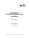
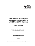
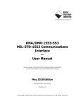
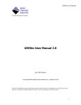
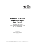
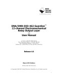
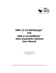
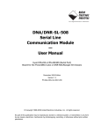
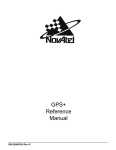
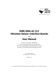
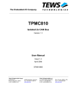
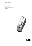
DNA/DNR-CAN-503
Controller Area Network Layer
—
User Manual
4-Port, Controller Area Network (CAN) Layer
for the PowerDNA Cube and RACKtangle chassis
September 2009 Edition
PN Man-DNx-503-0909
Version 3.8
© Copyright 1998-2009 United Electronic Industries, Inc. All rights reserved.
i
No part of this publication may be reproduced, stored in a retrieval system, or transmitted, in any form
by any means, electronic, mechanical, by photocopying, recording, or otherwise without prior written
permission.
Information furnished in this manual is believed to be accurate and reliable. However, no responsibility
is assumed for its use, or for any infringement of patents or other rights of third parties that may result
from its use.
All product names listed are trademarks or trade names of their respective companies.
See the UEI website for complete terms and conditions of sale:
http://www.ueidaq.com/company/terms.aspx
Contacting United Electronic Industries
Mailing Address:
27 Renmar Ave.
Walpole, MA 02081
U.S.A.
For a list of our distributors and partners in the US and around the world, please see
http://www.ueidaq.com/partners/
Support:
Telephone:
Fax:
(508) 921-4600
(508) 668-2350
Also see the FAQs and online “Live Help” feature on our web site.
Internet Support:
Support:
Web-Site:
FTP Site:
[email protected]
www.ueidaq.com
ftp://ftp.ueidaq.com
Product Disclaimer:
WARNING!
DO NOT USE PRODUCTS SOLD BY UNITED ELECTRONIC INDUSTRIES, INC. AS CRITICAL
COMPONENTS IN LIFE SUPPORT DEVICES OR SYSTEMS.
Products sold by United Electronic Industries, Inc. are not authorized for use as critical components in
life support devices or systems. A critical component is any component of a life support device or
system whose failure to perform can be reasonably expected to cause the failure of the life support
device or system, or to affect its safety or effectiveness. Any attempt to purchase any United Electronic
Industries, Inc. product for that purpose is null and void and United Electronic Industries Inc. accepts
no liability whatsoever in contract, tort, or otherwise whether or not resulting from our or our
employees' negligence or failure to detect an improper purchase.
ii
iii
Table of Contents
Chapter 1 Introduction
.................................................... 1
1.1
Organization of this manual . . . . . . . . . . . . . . . . . . . . . . . . . . . . . . . . . . . . . . . . . . . . 1
1.2
The CAN-503 Layer . . . . . . . . . . . . . . . . . . . . . . . . . . . . . . . . . . . . . . . . . . . . . . . . . . 3
1.3
1.3.1
1.3.2
What is a CAN? . . . . . . . . . . . . . . . . . . . . . . . . . . . . . . . . . . . . . . . . . . . . . . . . . . . . . 3
Standards. . . . . . . . . . . . . . . . . . . . . . . . . . . . . . . . . . . . . . . . . . . . . . . . . . . . . 4
Functional Description . . . . . . . . . . . . . . . . . . . . . . . . . . . . . . . . . . . . . . . . . . . 4
1.4
1.4.3
1.4.4
Physical & Data-Link Communication. . . . . . . . . . . . . . . . . . . . . . . . . . . . . . . . . . . . . 6
CAN Message Format . . . . . . . . . . . . . . . . . . . . . . . . . . . . . . . . . . . . . . . . . . . 7
Error Handling . . . . . . . . . . . . . . . . . . . . . . . . . . . . . . . . . . . . . . . . . . . . . . . . . 9
1.5
1.5.5
1.5.6
1.5.7
Architecture. . . . . . . . . . . . . . . . . . . . . . . . . . . . . . . . . . . . . . . . . . . . . . . . . . . . . . . .
CAN and the OSI Model – Overview . . . . . . . . . . . . . . . . . . . . . . . . . . . . . . .
Linking Abstraction. . . . . . . . . . . . . . . . . . . . . . . . . . . . . . . . . . . . . . . . . . . . .
Layer Capabilities . . . . . . . . . . . . . . . . . . . . . . . . . . . . . . . . . . . . . . . . . . . . .
1.6
Wiring & Connectors . . . . . . . . . . . . . . . . . . . . . . . . . . . . . . . . . . . . . . . . . . . . . . . . . 15
1.7
CAN Bus wiring. . . . . . . . . . . . . . . . . . . . . . . . . . . . . . . . . . . . . . . . . . . . . . . . . . . . . 16
11
11
13
13
Chapter 2 Programming with the High Level API . . . . . . . . . . . . . . . . . . . . . . . . . . . . . . 18
2.1
Creating a Session . . . . . . . . . . . . . . . . . . . . . . . . . . . . . . . . . . . . . . . . . . . . . . . . . . 18
2.2
2.2.1
Configuring the CAN Ports . . . . . . . . . . . . . . . . . . . . . . . . . . . . . . . . . . . . . . . . . . . . 18
Filtering CAN Messages . . . . . . . . . . . . . . . . . . . . . . . . . . . . . . . . . . . . . . . . 19
2.3
Configuring the Timing . . . . . . . . . . . . . . . . . . . . . . . . . . . . . . . . . . . . . . . . . . . . . . . 21
2.4
Reading Data . . . . . . . . . . . . . . . . . . . . . . . . . . . . . . . . . . . . . . . . . . . . . . . . . . . . . . 21
2.5
Writing Data . . . . . . . . . . . . . . . . . . . . . . . . . . . . . . . . . . . . . . . . . . . . . . . . . . . . . . . 22
2.6
Cleaning-up the Session. . . . . . . . . . . . . . . . . . . . . . . . . . . . . . . . . . . . . . . . . . . . . . 22
Chapter 3 Programming using the Low-Level API . . . . . . . . . . . . . . . . . . . . . . . . . . . . . 23
Appendix . . . . . . . . . . . . . . . . . . . . . . . . . . . . . . . . . . . . . . . . . . . . . . . . . . . . . . . . . . . . . . . . 24
Index
. . . . . . . . . . . . . . . . . . . . . . . . . . . . . . . . . . . . . . . . . . . . . . . . . . . . . . . . . . . . . . . . . . 25
© Copyright 2009
United Electronic Industries, Inc.
Tel: 508-921-4600
Date: September 2009
www.ueidaq.com
Vers: 3.8
File:CAN-503 ManualTOC.fm
iv
List of Figures
Chapter 1
1-1
1-2
1-3
1-4
1-5
1-6
1-7
1-8
Introduction . . . . . . . . . . . . . . . . . . . . . . . . . . . . . . . . . . . . . . . . . . . . . . . . . . . . 1
Photos of DNR- and DNA-CAN-503 Modules................................................................ 3
CAN and the ISO/OSI Model ....................................................................................... 11
Physical and Data-Link Layers and Logic Circuitry...................................................... 12
Logic Block Diagram: CAN-503 Overview ................................................................... 12
Logic Block Diagram — CAN-503 Detail ..................................................................... 13
CAN-503 with 4-port DNA-CAN-CBL Attached............................................................ 15
Pinout Diagram for DNA-CAN-503 Layer .................................................................... 16
CAN Nodes Connected to a CANbus using Standard 120-ohm Termination.............. 17
Chapter 2
Programming with the High-Level API . . . . . . . . . . . . . . . . . . . . . . . . . . . . . 13
(None)
Chapter 3
Programming with the Low-Level API . . . . . . . . . . . . . . . . . . . . . . . . . . . . . . 16
(None)
© Copyright 2009
United Electronic Industries, Inc.
Tel: 508-921-4600
Date: September 2009
www.ueidaq.com
Vers: 3.8
File:CAN-503 ManualLOF.fm
DNx-CAN-503 Layer
Chapter 1
Introduction
Chapter 1
Introduction
This document outlines the feature-set and describes the operation of the
DNx-CAN-503 Controller Area Network boards. The DNA- version is designed
for use with a PowerDNA Cube data acquisition system. The DNR- version is
designed for use with a DNR-12 RACKtangle or a DNR-6 HalfRACK system.
Both versions are functionally identical. This module enables communication
with a Controller Area Network (CAN) over a CAN bus. Please ensure that you
have the PowerDNA Software Suite installed before attempting to run examples.
1.1
Organization This DNx-CAN-503 User Manual is organized as follows:
of this manual • Introduction
This chapter provides an overview of the document content, the device architecture, connectivity, and logic of the layer. It also includes wiring schemes,
notes, and specifications.
© Copyright 2009
United Electronic Industries, Inc.
•
Programming with the High-Level API
This chapter provides an overview of the how to create a session, configure
the session for CAN bus communication, and interpret results on the
CAN-503 series layer.
•
Programming with the Low-Level API
This chapter describes the use of low-level API commands for configuring
and using the CAN-503 series layer.
•
Appendix A: Accessories
This appendix provides a list of accessories available for CAN-503 layer(s).
•
Appendix B: Calibration
This appendix outlines the calibration procedure for the CAN-503 series
layer.
•
Index
This is an alphabetical listing of the topics covered in this manual.
Tel: 508-921-4600
Date: September 2009
www.ueidaq.com
Vers: 3.8
File: CAN-503 Chapter 1.fm
1
DNx-CAN-503 Layer
Chapter 1
Introduction
Document Conventions
To help you get the most out of this manual and our products, please note that
we use the following conventions:
Tips are designed to highlight quick ways to get the job done, or to
reveal good ideas you might not discover on your own.
NOTE: Notes alert you to important information.
CAUTION! Caution advises you of precautions to take to avoid injury,
data loss, and damage to your boards or a system crash.
Text formatted in bold typeface generally represents text that should be entered
verbatim. For instance, it can represent a command, as in the following
example: “You can instruct users how to run setup using a command such as
setup.exe.”
Frequently Asked Questions
For frequently answered questions, application notes, and support, visit us
online at:
http://www.ueidaq.com/faq/
© Copyright 2009
United Electronic Industries, Inc.
Tel: 508-921-4600
Date: September 2009
www.ueidaq.com
Vers: 3.8
File: CAN-503 Chapter 1.fm
2
DNx-CAN-503 Layer
Chapter 1
Introduction
1.2
The CAN-503
Layer
The CAN-503 layer has the following features:
•
4 independent CAN ports
•
Bit transfer rates of 10, 20, 50, 100, 125, 250, 500, 800, 1000 kbps
NOTE: UEISIM support of the DNx-CAN-503 is limited to 300 fps input and
1000 fps output.
•
24MHz base clock
•
Completely independent bit rate settings for every port
•
250V DC max isolation between ports; ports and circuitry
•
Hot plugging support for CAN devices
•
Interrupt-based error detection
•
Fully compatible with ISO 11898 standard
•
CAN 2.0a-compatible, 11-bit, and CAN 2.0b, 29-bit identifiers
•
Message targeting and filtering
•
Weight: of layer: 120grams - and core: 290g – in a cube: 630g (22.2oz)
DNR-CAN-503
DNA-CAN-503
Figure 1-1. Photos of DNR- and DNA-CAN-503 Modules
1.3
What is a
CAN?
A Controller Area Network (CAN) is a multi-cast, shared, serial bus standard
designed to operate in electromagnetically noisy environments, such as
automotive and general industrial locations. The shared serial bus is called a
CAN bus.
Machines, sensors, and other devices on the CAN bus are nodes.
For example, in a vehicle the CAN bus can control a car’s dashboard displays,
power windows, power locks, windshield wipers, exterior lighting, and so forth.
Another higher-speed CAN bus can control the engine and brake system
operation.
© Copyright 2009
United Electronic Industries, Inc.
Tel: 508-921-4600
Date: September 2009
www.ueidaq.com
Vers: 3.8
File: CAN-503 Chapter 1.fm
3
DNx-CAN-503 Layer
Chapter 1
Introduction
1.3.1
Standards
CAN communication takes the form of the ISO/OSI 7-layer model, where:
•
Layers 3 to 7 (application) are handled by user software (e.g.,
CANOpen, etc.)
•
Layer 2 (data-link) is outlined by ISO 11898-1 and the CAN 2.0
specification.
•
Layer 1 (physical, electrical signaling and wiring) is defined by ISO
11898.
ISO 11898 defines the protocol for controller signaling in road vehicles:
•
ISO/DIS 11898-1: Road vehicles — CAN — Part 1: Data link layer and
physical signaling
•
ISO/DIS 11898-2: Road vehicles — CAN — Part 2: High-speed medium
access unit
•
ISO/CD 11898-3: Road vehicles — CAN — Part 3: Low-speed fault
tolerant medium-dependent interface
•
ISO/CD 11898-4: Road vehicles — CAN — Part 4: Time triggered
communication
The ISO standards are listed for reference and theory only; the CAN-503
provides transparent access directly to message frames transmitted on the
CAN-bus. The remainder of this document refers to: the ISO 11898 CAN bus
and ISO 11898 + CAN2.0-compliant nodes.
1.3.2
1.3.2.1
Functional
Description
The data messages transmitted by any node on a CAN bus do not contain
addresses of either the transmitting node or any receiving node. The message
itself contains a unique identifier that all nodes receive. Each receiving node
performs an acceptance test on the identifier to decide whether or not the
message is of interest to that node. If it is, the message is processed. If not, the
message is ignored. The identifier also determines the importance of the
message. The lower the numerical value, the higher the priority. If two or more
nodes try to transmit at the same time, a non-destructive arbitration function
ensures that messages are sent in priority order and no messages are lost. This
arbitration technique is described below.
Bit Types
Bits are classified as either “dominant” or “recessive.” The bus can have one of
two complementary logical values — dominant or recessive. If simultaneous
transmission of dominant and recessive bits occurs, the resulting value will be
dominant. For example, when using a wired-AND implementation of the bus, the
dominant level is represented by a logical 0 and the recessive level by a logical
1. Physical states (voltage, light level, etc.) that represent the logical levels are
not given in this specification.
All nodes can listen and transmit at the same time. If a node transmits a
dominant bit, it will see a dominant bit on the bus. Also, the transmitting node will
not know if another node was trying to transmit. If a node transmits a recessive
bit, however, and a dominant bit is seen on the bus, the node knows that
someone else is on the bus.
1.3.2.2
Bit Encoding
© Copyright 2009
United Electronic Industries, Inc.
CAN uses NRZ “non-return to zero” encoding with bit stuffing over a differential
2-wire bus, usually twisted-pair. This encoding ensures compact messages with
minimum transitions and high noise immunity.
Tel: 508-921-4600
Date: September 2009
www.ueidaq.com
Vers: 3.8
File: CAN-503 Chapter 1.fm
4
DNx-CAN-503 Layer
Chapter 1
Introduction
1.3.2.3
Bit Timing
The ISO standard, ISO 11898, specifies that each bit on the CAN bus is divided
into at least 4 segments or quanta, as follows:
•
Synchronization segment
•
Propagation segment
•
Phase 1 segment
•
Phase 2 segment
The Sync segment, always one segment long, is used for synchronizing clocks.
A bit edge should occur within this segment whenever a data change occurs.
The Propagation segment compensates for any physical delays in the network.
Phase 1 segment is a buffer that may be shortened or lengthened to keep the
clocks in sync.
Phase 2 segment is also a buffer that may be adjusted to compensate for
negative phase errors and drift in oscillators.
The bit sample is always taken at the end of Phase 1 segment.
When any node receives a data or remote frame, the receiver must sync its
clock to the transmitter. “Hard synchronization” occurs on the recessive-todominant transition of the start bit and the bit time is restarted from that edge.
If a bit edge does not occur during the Sync segment, however,
“resynchronization” is required. To correct for any phase differences between
transmitter and receiver oscillators, the system automatically shortens or
lengthens the bit time to eliminate the error. The maximum number of time
segments used for the adjustment is determined by a user-programmable
parameter called Synchronization Jump Width (SJW).
1.3.2.4
Reliability
A CAN system can operate successfully in very severe environments. It also
uses a sophisticated error checking technique to ensure that all transmission
errors are immediately detected. In applications with speeds below 125 kbps, a
CAN bus will continue to operate (although with higher noise) if either of the two
bus wires is broken, if either wire is shorted to ground, or if either wire is shorted
to the power supply. The purpose of this mode is to permit the bus to operate
after a car crash has severed one of the lines. Each node continues to monitor
the faulty line and will resume two-wire operation when the fault condition is
removed.
1.3.2.5
Design
Flexibility
The fact that CAN messages are not addressed to specific nodes offers great
flexibility in designing a system. Each node decides for itself whether or not the
transmitted message is relevant to it. As a result, you can add new receiving
nodes without having to make any changes to existing hardware or software.
Measurement information needed by several controllers can be broadcast over
the bus, eliminating the need for individual sensors for each controller.
1.3.2.6
Bus
Arbitration
To assign priority to messages, CAN uses the CSMA/CD method (Carrier
Sense, Multiple Access with Collision Detect) plus a non-destructive bus
arbitration scheme to resolve conflicts. The numerical value of each message
identifier is assigned by the system designer at the start of the project. This
value, by definition, also sets the relative priority of a message. The identifier
with the lowest value has the highest priority. Any conflicts are resolved by
bitwise arbitration and a wired-AND method, as described previously.
© Copyright 2009
United Electronic Industries, Inc.
Tel: 508-921-4600
Date: September 2009
www.ueidaq.com
Vers: 3.8
File: CAN-503 Chapter 1.fm
5
DNx-CAN-503 Layer
Chapter 1
Introduction
A key feature of CAN bus arbitration is that the first node delays transmitting if
some other node sends a dominant bit whenever the first node sends its first
recessive bit. Since the identifier is contained in the first part of the message
transmitted, all nodes except one will have delayed transmission by the time the
identifier has been sent. The message identifier, therefore, determines which
messages have priority.
At the start of a message frame, each node sends a single dominant bit, called
the start of frame (SOF) bit. All listening nodes will see bus activity and will
therefore not attempt to start transmission until the current message is
complete. The only chance for collision is between nodes that simultaneously
send an SOF bit. These nodes remain in step for the whole message or until all
except one back off. After the SOF bit is sent, the arbitration field is transmitted.
The winning node will always have the lowest value arbitration field, because it
will be the first to transmit a dominant bit, when other nodes are transmitting
recessive bits. You can therefore consider the numerical value (low to high) of
the arbitration field to be the priority of the message.
Since the highest priority message is unchanged, the arbitration is
nondestructive. In fact, the node transmitting the message is not even aware
that a collision occurred. The only way for a node to detect a collision is for the
node to observe something on the bus that is different from what it transmitted.
As a result, the successful node and any other listening nodes never see any
evidence of a collision on the bus.
The highest priority message is always transmitted successfully, but at the
expense of lower-priority messages. The goal is to ensure that the highestpriority work is finished as soon as possible. Although it is still possible to miss a
hard real-time deadline, there should never be a situation where a high priority
task misses a deadline because it was waiting for a lower-priority task to run.
If several nodes clash, one will win out. After that winning message is complete,
all of the “non-winners” try again. In the second round, the next lowest-value
arbitration field wins, and the process repeats. There's no reason that the
lowest-value arbitration field can’t be transmitted again, however. Therefore, it is
important to be aware that the CAN bus doesn't prevent this from happening —
the user must ensure that no single message type dominates the bus activity.
The arbitration field can be 11 or 29 bits long, depending on which CAN protocol
you use. You can use the first few bits for priority assignment and the remaining
bits to identify the type of message. The CAN standard doesn't rigidly specify the
meaning of those bits, but the several higher-level CAN-compatible protocols
do.
1.4
Physical &
Data-Link
Communication
The CAN bus is a shared, multi master, event-oriented message transmission
bus. Any node may transmit on the bus when the bus is idle (multi master), and
communicate with any other node(s) that are in listening mode. Nodes
constantly listen to the bus and filter out messages not relevant to them as
determined by the acceptance mask.
To determine which node (of the many connected nodes) may transmit on an
idle bus, a non-destructive contention-based bus arbitration scheme (CSMA/
CD) is used, as described above. Nodes always listen. When they notice that
the bus is idle, they transmit their 11 or 29-bit object identifier. The node with the
lowest object identifier number is given priority to transmit a frame; and then the
process repeats.
© Copyright 2009
United Electronic Industries, Inc.
Tel: 508-921-4600
Date: September 2009
www.ueidaq.com
Vers: 3.8
File: CAN-503 Chapter 1.fm
6
DNx-CAN-503 Layer
Chapter 1
Introduction
1.4.3
CAN Message When a device has transmission permission on the bus, it broadcasts a
(message) frame to the other connected devices.
Format
There are four types of frames:
•
Remote Frame: requests transmission of a specific identifier
•
Error Frame: transmitted by any node detecting an error
•
Overload Frame: request to inject a delay between data/remote frames
•
Data Frame: a frame that contains data
Two different types of Data Frames are defined (and supported by the CAN503):
Base Frame Format, aka Standard CAN, aka CAN 2.0A message frame.
These use an 11-bit identifier, or 2048 possible message combinations.
Extended Frame Format, aka Extended CAN, aka CAN 2.0B message frame.
These frames use a larger 29-bit identifier, for 512 million message
combinations. This mode, however, may not be supported in older CAN2.0Aonly controllers.
© Copyright 2009
United Electronic Industries, Inc.
Tel: 508-921-4600
Date: September 2009
www.ueidaq.com
Vers: 3.8
File: CAN-503 Chapter 1.fm
7
DNx-CAN-503 Layer
Chapter 1
Introduction
1.4.3.1
2.0A Format
Description
A Standard CAN (Version 2.0A) Message Frame has the following
structure:
Field Name
Length
(bits)
Purpose
Bus Idle
SOF
Arbitration
Field
Control
Field
Data Field
CRC Field
Start of Frame
1
Recessive bit
Identifier A
11
First part of the (unique) identifier for the
data.
Remote Transmission Request
(RTR)
1
Must be recessive.Discriminates between
a Data Frame and a request for data from a
remote node.
Two Reserved bits r0 and r1
2
Reserved for future use.
Data Length Code (DLC)
4
Number of bytes in the Data Field that
follows.
Data field
0 to 8
bytes
CRC
15
Cyclic redundancy check
CRC delimiter
1
Must be recessive.
ACK slot
1
Transmitter sends recessive. Any receiver
can override with a dominant bit.
ACK delimiter
1
Must be recessive.
End-of-frame (EOF)
7
Must be recessive.
INTermission Field
3
3 recessive bits
ACK
EOF
Data to be transmitted (length = DLC field).
After three INTermission periods, the bus is
called “free.” Bus idle time may be any
value including zero.
INT
Bus Idle
1.4.3.2
2.0B Format
© Copyright 2009
United Electronic Industries, Inc.
The CAN 2.0B format uses a 29-bit identifier instead of the 11-bit identifier used
by CAN 2.0A. This format was developed to meet the needs of automotive
applications, but also to be compatible with 2.0A devices. The differences
between the two formats are:
•
In CAN 2.0B, the arbitration field has two fields – the Base ID (11-bits for
compatibility with 2.0A) and the Extension ID (18-bits) for a combined
length of 29 bits.
•
An additional bit, Identifier Extension bit (IDE), identifies the use of the
extended format.
•
The Arbitration Field also includes a Substitute Remote Request (SSR)
bit that ensures priority of the Standard Data Frame if both Standard and
Extended Data Frames have the same 11-bit identifier.
•
All other fields in 2.0B are the same as those in 2.0A.
Tel: 508-921-4600
Date: September 2009
www.ueidaq.com
Vers: 3.8
File: CAN-503 Chapter 1.fm
8
DNx-CAN-503 Layer
Chapter 1
Introduction
Controllers designed for 2.0B format can transmit and receive messages in
either 2.0A or 2.0B formats. Controllers designed for 2.0A format are available
in two types. The first transmits and receives only 2.0A messages and flags an
error when a 2.0B message is detected. The second transmits, receives, and
acknowledges 2.0A messages, but does not process them.
The Extended Frame Format is structured as follows:
Description
Length
(bits)
Field Name
Purpose
Bus Idle
SOF
Arbitration
Field
Start-of-frame (SOF)
1
Recessive bit signals start of frame
transmission.
Identifier A
11
First part of the (unique) identifier for the
data.
Substitute remote request (SRR)
1
Must be recessive.
Identifier extension bit (IDE)
1
Must be recessive.
Identifier B
18
Second part of the (unique) identifier for the
data.
Remote transmission request
(RTR)
1
Must be dominant.
Reserved bits (r0, r1)
2
Reserved bits (must be set dominant, but
are accepted as either dominant or
recessive).
Data length code (DLC)
4
Number of bytes of data (0-8 bytes).
Control Field
Data Field
CRC Field
Data field
0 to 8
bytes
CRC
15
Cyclic redundancy check
CRC delimiter
1
Must be recessive.
ACK slot
1
Transmitter sends recessive. Any receiver
can assert a dominant.
ACK delimiter
1
Must be recessive.
End-of-frame (EOF)
7
Must be recessive.
ACK
EOF
Data to be transmitted (length = DLC field).
Bus Idle
1.4.4
Error Handling CAN uses several message-level techniques to detect errors, as follows:
•
CRC checks
•
Frame checks
•
ACKnowledgement Error Checks
CAN also monitors bit levels for errors — comparing actual bit levels with those
transmitted. If a difference is detected, the transmitter flags a bit error.
© Copyright 2009
United Electronic Industries, Inc.
Tel: 508-921-4600
Date: September 2009
www.ueidaq.com
Vers: 3.8
File: CAN-503 Chapter 1.fm
9
DNx-CAN-503 Layer
Chapter 1
Introduction
To increase system reliability, CAN implements “bit stuffing.” Whenever a
transmitter sends five consecutive bits of the same type, it automatically adds a
bit of opposite polarity into the message. Any node receiving the message
automatically removes (de-stuffs) this added bit before processing the message.
If any receiving node detects six consecutive bits of the same polarity, therefore,
it records a “stuff error”.
1.4.4.1
CRC Check
The transmitter computes a CRC code based on the content of each message it
transmits and inserts it into the message frame. Any receiver that accepts the
message makes the same computation and compares the two results. If any
difference is found, an error is flagged.
1.4.4.2
Frame Check
The CAN format specified that certain bit values must be present at specific
locations in the message frame. If a receiver sees the wrong value in any
position, it flags a Form (or Format) Error.
1.4.4.3
ACK Check
If a transmitter send a message and does not receive acknowledgment, it flags
an ACK Error.
1.4.4.4
Error Frame
If any node detects an error of any kind, it sends an Error Frame. This aborts
transmission and prevents any other node from accepting the message
containing the error.
1.4.4.5
Error
Confinement
The CAN system has a complex system of distinguishing between short-term
and long-term errors. Whenever an error is detected, an error count is added to
one of two error counters on each node. In simplified terms, receive errors are
accumulated with a weighting of 1 and transmitter errors are accumulated with a
weighting of 8. Conversely, every good message decrements the counters
accordingly, with zero as a limit. The values stored in each counter at any given
time determine the error status of a node.
There are three modes of error status: Error Active, Error Passive, and Bus Off
Mode. The Error Active Mode is the normal state of a node. To be classified as
Error Active, the error counters must contain values less than 127.
If the value in an error counter exceeds 127, the mode changes to Error Passive
Mode. In this mode, the node can still transmit and receive messages, but is
constrained in how it handles errors it detects.
If the value in an error counter exceeds 255, the node takes itself off the bus and
goes into Bus Off Mode. This action removes a permanently malfunctioning
(“babbling idiot”) node from the system but leaves all others on the bus
unaffected.
This system of error handling, although complex, ensures very high integrity of
data communication in noisy environments.
© Copyright 2009
United Electronic Industries, Inc.
Tel: 508-921-4600
Date: September 2009
www.ueidaq.com
Vers: 3.8
File: CAN-503 Chapter 1.fm
10
DNx-CAN-503 Layer
Chapter 1
Introduction
1.5
1.5.5
Architecture
CAN and the
OSI Model –
Overview
The CAN communication stack may be represented using the OSI model, as
shown in Figure 1-2.
CAN-based Protocol Standard
Presentation
Session
Transport
Network
Data
DataLink
Link
ISO11898
CAN
2.0A
Software
Application
Physical
Physical
Software support facilities that
are not part of the OSI Model
– Create CAN frames
– Transceive CAN frames
API
UeiDaq Framework
Driver
PowerDNA Driver
Logical Link Control
Acceptance Filtering
Recovery Management
Media Access Control
Frame Coding
Serialization/deserialization
Error Detection
CAN-503
CAN Controller
SJA1000
Physical Signaling
Bit Encoding/Decoding & Timing
PMA
Driver/Receiver Characteristics
CAN-503
CAN Transceiver
TJA1050
CAN-503 Connectors
MO Interface
Cable & Connectors
Cables
Figure 1-2. CAN and the ISO/OSI Model
The physical and data-link layers are implemented by the CAN-503 hardware,
which is detailed in the next section. In concept, the CAN-503 converts CAN
frames into (or from) electrical signals.
Frames are retrieved from the CAN-503 by the PowerDNA driver and passed to
the user application (usually by facility of the UeiDaq Framework). The user
application is allowed the freedom and responsibility of implementing layers
above data-link and physical with any additional protocol you choose to use
(such as CANopen, J1939, DeviceNet, SDS, CAN Kingdom, proprietary, or
custom).
At the hardware level, data passes at the physical level through cabling and the
connector through the TJA1050 CAN transmitter/receiver, which is controlled by
the SJA100 CAN controller:
© Copyright 2009
United Electronic Industries, Inc.
Tel: 508-921-4600
Date: September 2009
www.ueidaq.com
Vers: 3.8
File: CAN-503 Chapter 1.fm
11
DNx-CAN-503 Layer
Chapter 1
Introduction
Figure 1-3. Physical and Data-Link Layers and Logic Circuitry
CAN Interface
Controller
CAN
Transceiver
CAN Interface
Controller
CAN
Transceiver
CAN Interface
Controller
CAN
Transceiver
CAN Interface
Controller
32-bit 66-MHz bus
CAN
Transceiver
NIS FPGA
Control Logic
DB-37 Connector
g
Electrical Isolation
Figure 1-4. Logic Block Diagram: CAN-503 Overview
As illustrated in the diagram of Figure 1-5, the CAN bus transmits/receives an
electrical signal that flows through the DB-9 to DB-37 connector, from/to the
TJA1050 CAN transceiver chip. The TJA1050 CAN transceiver acts as an
interface to the SJA1000 CAN interface controller – it assists the SJA1000 by
handling transmission/reception to/from the CAN bus.
The transceiver and controller are isolated from one another by a high-speed
electrical isolation IC. There are four TJA1050 » isolation » SJA1000 structures,
one per port; isolation is per-port.
The SJA1000 is in turn controlled by an FPGA Control Chip – which is the layer’s
control chip. The FPGA works in conjunction with the cube’s core module logic.
© Copyright 2009
United Electronic Industries, Inc.
Tel: 508-921-4600
Date: September 2009
www.ueidaq.com
Vers: 3.8
File: CAN-503 Chapter 1.fm
12
TJA1050
(4x, 1 per
channel)
CLI NIS FPGA standard logic – includes input/output
channel list, Coldfire engine, etc.
CAN
Transceivers
High-speed (15 MHz) Electrical Isolation
DB-37 connector printed out to match MOXA
4-port cable
DNx-CAN-503 Layer
Chapter 1
Introduction
SJA 1000
CAN
Interface
Controller
(4x, 1 per
channel)
DC/DC, per channel,
used to power CAN
transmitters
Figure 1-5. Logic Block Diagram — CAN-503 Detail
1.5.6
Linking
Abstraction
The CAN-503 layer is a device that converts the electrical signal traveling along
the CAN bus into raw CAN frame(s).
For the sake of simplicity, ignore the majority of electrical signaling methods
described by the ISO 11898 standard and focus on the UeiDaq Framework API.
The UeiDaq Framework API is a tool installed with the PowerDNA Software
Suite that provides easy access to the CAN-503’s functionality. Framework is a
programming facility that allows you to connect to a cube transparently, and then
configure the CAN-503 to communicate with other CAN devices. Attach to the
CAN-bus and then send and/or receive CAN packets.
Framework sends and receives only raw CAN frames – it does not generate
their content. Frame content is the responsibility of higher-level CAN protocols
(e.g. CANopen, J1939, DeviceNet, SDS, CAN Kingdom, etc.).
The Framework implementation is best described in an example, as illustrated
in Chapter 2.
1.5.7
Layer
Capabilities
© Copyright 2009
United Electronic Industries, Inc.
The controller is capable of communicating with the CAN 2.0a and CAN 2.0b
protocols. Controller communication speeds are software selectable between 10
and 1000kbps – speed is dependent on noise and length of the cable. The CAN
specification recommends a maximum speed of 125k for cables up to 500m in
length, and a max. speed of 1M for cables up to 40m. The device can be
operated in single-scan, continuous, or continuous with FIFO modes. The
64-byte FIFO on the SJA1000 can store up to 21 messages. The controller can
operate in active transmission mode, passive listen-only mode, or self-test
mode. The controller has built-in filter-circuitry to target specific messages.
Tel: 508-921-4600
Date: September 2009
www.ueidaq.com
Vers: 3.8
File: CAN-503 Chapter 1.fm
13
DNx-CAN-503 Layer
Chapter 1
Introduction
The TJA1050 uses an EMI-resistant differential receiver to capture data from the
line. It can operate in “listen mode” where the transmitter is disabled, and can
send/receive raw CAN data at speeds up to 1 Mbaud. In the CAN-503
implementation, bandwidth of 4 ports at 250k each (e.g. 1000k total) can be
sustained effortlessly over a local CAN bus. Also, note that when powered down,
the TJA1050 and the CAN-503 do not disturb the bus lines.
Current implementation of the CAN interface on the Cube provides only registerlevel access to the Philips SJA1000 CAN interface controllers. Depending on
the demand and speed requirements, future implementations may include perport input and output FIFOs and full interrupt/error handling in logic. The CAN
interface is mapped into PowerDNA address space as a set of read/write
registers.
NOTE: UEISIM support of the DNx-CAN-503 is limited to 300 fps input and
1000 fps output.
© Copyright 2009
United Electronic Industries, Inc.
Tel: 508-921-4600
Date: September 2009
www.ueidaq.com
Vers: 3.8
File: CAN-503 Chapter 1.fm
14
DNx-CAN-503 Layer
Chapter 1
Introduction
1.6
Wiring &
Connectors
A DNA-CAN-CBL cable (pictured below) from the CAN-503’s 37-pin connector
provides four individual 9-pin ports; they are labeled by port as (1), (2), (3), (4),
with each label molded into the connector. The 9-pin connectors are called
stubs.
Port 1
Port 2
Port 3
Port 4
Figure 1-6. CAN-503 with 4-port DNA-CAN-CBL Attached
The following signals are located at the connector:
•
CAN-Lx – Dominant Low line for port x.
•
CAN-Hx – Dominant High line for port x.
•
CAN-GNDx – Ground reference voltage for port x.
Both the CAN_L and CAN_H lines are protected from automotive electrical
transients by ISO 7637 — electrical transient transmission by capacitive and
inductive coupling via lines other than supply lines in road vehicles. To take
advantage of noise-cancellation properties, use twisted-pair cabling (for >1m).
The B-size 37-pin female D-Sub connector on the CAN-503 is divided into four
9-pin D-connector CAN ports by a DNA-CAN-CBL with the following pinouts:
© Copyright 2009
United Electronic Industries, Inc.
Tel: 508-921-4600
Date: September 2009
www.ueidaq.com
Vers: 3.8
File: CAN-503 Chapter 1.fm
15
DNx-CAN-503 Layer
Chapter 1
Introduction
Figure 1-7 Pinout Diagram for DNA-CAN-503 Layer
1.7
CAN Bus
wiring
As shown in Figure 1-8, the ISO11898 bus consists of two wires, terminated at
both ends by resistors.
CAN devices (nodes) connect their CAN_L and CAN_H lines to the two-wire
CANbus. A node transmits by sending the signal (HIGH or LOW) on CAN_H and
the inverse of the signal on CAN_L. Only the two nodes at each the end of the
bus must have a terminating resistor (100-130 ohms). The terminating resistors
remove signal reflection at the end of the bus and balance the DC voltage levels.
© Copyright 2009
United Electronic Industries, Inc.
Tel: 508-921-4600
Date: September 2009
www.ueidaq.com
Vers: 3.8
File: CAN-503 Chapter 1.fm
16
DNx-CAN-503 Layer
Chapter 1
Introduction
Layer Controller
CAN Interface Controller
Tx
Rx
optical
isolation
CAN Transceiver
Node
Node
120 ohm
CAN_L CAN_H
120 ohm
CAN_L CAN_H
CAN_L CAN_H
CANbus
Figure 1-8. CAN Nodes Connected to a CANbus using Standard
120-ohm Termination
The bus cable length should not exceed 40m (130ft) at 1Mbps, or 6.7km at
10kbps, due to the cable propagation delay (5nS/m).
For cables longer than 1m (3.28 ft), noise may cause timeouts when using nontwisted-pair cabling; if you experience difficulty, use twisted-pair cabling.
© Copyright 2009
United Electronic Industries, Inc.
Tel: 508-921-4600
Date: September 2009
www.ueidaq.com
Vers: 3.8
File: CAN-503 Chapter 1.fm
17
DNx-CAN-503 Layer
Chapter 2
Programming with the High Level API
Chapter 2
Programming with the High Level API
This section describes how to program the DNx-CAN-503 using UeiDaq’s
Framework High Level API.
Since UeiDaq Framework is object oriented, its objects can be manipulated in
the same manner in various development environments such as Visual C++,
Visual Basic, LabVIEW, or DASYLab.
Framework comes bundled with examples for supported programming
languages. They are located under the UEI programs group in:
Start » Programs » UEI » Framework » Examples
The following subsections focus on the C++ API, but the concept is the same
regardless of programming language.
Please refer to the “UeiDaq Framework User Manual” for more information on
using other programming languages.
2.1
Creating a
Session
The Session object controls all operations on your PowerDNA device.
Therefore, the first task is to create a session object:
CUeiSession session;
2.2
Configuring
Framework uses resource strings to select which device, subsystem, and
the CAN Ports channels to use within a session. The resource string syntax is similar to a web
URL:
<device class>://<IP address>/<Device Id>/<Subsystem><Channel list>
For PowerDNA, the device class is pdna.
For example, the following resource string selects CAN ports 0,2,3 on device 1
at IP address 192.168.100.2: “pdna://192.168.100.2/Dev1/Can0,2,3”.
In addition to the resource, you will also configure:
•
Port Speed
•
Frame Format: basic using an 11-bit identifier or extended using a 29-bit
identifier.
•
Port Mode: normal or passive listener.
•
Acceptance Mask: used to filter incoming frames. The mask selects
which bits within the arbitration ID will be used for filtering.
•
Acceptance Code: the arbitration ID bits selected by the acceptance
mask are compared to the acceptance code and the frame is rejected if
there is any difference.
Setting the acceptance mask to 0xFFFFFFFF and the acceptance code to 0
disables filtering.
© Copyright 2009
United Electronic Industries, Inc.
Tel: 508-921-4600
Date: September 2009
www.ueidaq.com
Vers: 3.8
File: CAN-503 Chapter 2.fm
18
DNx-CAN-503 Layer
Chapter 2
Programming with the High Level API
// Configure CAN ports 0,2,3 on device 0
session.CreateCANPort("pdna://192.168.100.2/Dev0/Can0,2,3",
UeiCANBitsPerSecond500K,
UeiCANFrameExtended,
UeiCANPortModeNormal,
0xFFFFFFFF,
0);
2.2.1
Filtering CAN
Messages
The acceptance mask defines the bits that are relevant (0 is relevant, 1 is not)
for comparison with the acceptance code.
The way you pack the bits in the mask and code depends on whether the CAN
interface is configured in Basic or Extended mode and also on whether you want
to filter incoming frames that use 11-bit IDs or frames that use 29-bit IDs.
The algorithm for defining the acceptance code and mask is described in the
document at http://www.nxp.com/acrobat_download/applicationnotes/
AN97076.pdf, starting at page 19.
Example 1, 11-bit filtering:
The following shows how to make a common filter configuration that
rejects 0x241, 0x514, and 0x4E1 and accepts 0x541 and 0x641.
0x241 010 0100 0001 ; lay out the bits to reject, convert hex to
; binary
0x514 101 0001 0100
0x4E1 100 1110 0001 ; lay out the bits to accept
0x541 101 0100 0001
0x641 110 0100 0001
Now shift the groupings left by one place and pad with 21 x’s on the
right (to make it a full 32-bit word).
reject
“
“
0100 1000 001x xxxx xxxx xxxx xxxx xxxx
1010 0010 100x xxxx xxxx xxxx xxxx xxxx
1001 1100 001x xxxx xxxx xxxx xxxx xxxx
accept
“
1010 1000 001x xxxx xxxx xxxx xxxx xxxx
1100 1000 001x xxxx xxxx xxxx xxxx xxxx
‘row a’: 1xx0 100x
;
;
;
0x1x xxxx xxxx xxxx xxxx xxxx
for each column, if both accept bits are the same
and at least one reject bit is different,
then copy the accept bit, otherwise make it x
1000 1000 0010 0000 0000 0000 0000 0000 ; make code: copy ‘row a’ and
; make all x’s be zero
8
8
2
0
0
0
0
0 ; convert binary to hex,
; the acceptance code = 0x88200000
© Copyright 2009
United Electronic Industries, Inc.
Tel: 508-921-4600
Date: September 2009
www.ueidaq.com
Vers: 3.8
File: CAN-503 Chapter 2.fm
19
DNx-CAN-503 Layer
Chapter 2
Programming with the High Level API
0110 0001 0101 1111 1111 1111 1111
;
;
6
1
5
F
F
F
F
;
1111 ; make mask: put a 1 where
‘row a’
has an x. The others become zero.
F ; convert binary to hex
the acceptance mask = 0x615FFFFF
Example 2, 29-bit filtering:
In this example, you want to receive messages with ID’s 18FEEE00,
18FEF100 and 0CF00400 and receive as few other messages as possible.
0x18FEEE00 1 1000 1111 1110 1110 1110 0000 0000 ;lay out the bits
0x18FEF100 1 1000 1111 1110 1111 0001 0000 0000 ;
“
0x0CF00400 0 1100 1111 0000 0000 0100 0000 0000 ;
“
1100 0111 1111 0111 0111 0000 0000 0xxx
1100 0111 1111 0111 1000 1000 0000 0xxx
0110 0111 1000 0000 0010 0000 0000 0xxx
; shift groupings left, pad
; 3 x’s
;
“
;
“
x1x0 0111 1xxx 0xxx xxxx x000 0000 0xxx ; find what’s common to all 3,
;
else x
0100 0111 1000 0000 0000 0000 0000 0000 ; make code, take common,
;
x’s -> 0
4
7
8
0
0
0
0
0 ; convert code to hex
;code is 0x47800000
1010 0000 0111 0111 1111 1000 0000 0111 ; make mask, x’s become 1’s,
; else 0
A
0
7
7
F
8
0
7 ; convert mask to hex
; mask is 0xA077F807
2.3
Configuring
the Timing
You need to configure the CAN-503 to use the “messaging” timing mode.
Messages are equivalent to CAN frames and are represented in C++ with the
structure tUeiCANFrame:
struct tUeiCanFrame
{
uInt32
Id;// arbitration Id of the frame
uInt32
IsRemote;// 1 if the frame is remote
uInt32
DataSize;// number of bytes in the payload
uInt8
Data[8];// payload
};
The CAN-503 can be programmed to wait for a certain number of messages to
be received before notifying the session.
It is also possible to program the maximum amount of time to wait for the
specified number of messages before notifying the session.
© Copyright 2009
United Electronic Industries, Inc.
Tel: 508-921-4600
Date: September 2009
www.ueidaq.com
Vers: 3.8
File: CAN-503 Chapter 2.fm
20
DNx-CAN-503 Layer
Chapter 2
Programming with the High Level API
The following sample shows how to configure the messaging I/O mode to be
notified when 10 frames have been received or every second. (If the CAN port
receives less than 10 frames per second, it will return whatever number of
frames is available every second).
CANSession.ConfigureTimingForMessagingIO(10, 1.0);
2.4
Reading Data Reading data from the CAN-503 is done using a reader object. As there is no
multiplexing of data (contrary to what’s being done with AI, DI, or CI sessions),
you need to create one reader object per CAN port to be able to read from each
port in the port list.
The following sample code shows how to create a reader object tied to port 1
and read at most 10 frames from the CAN bus.
// Create a reader and link it to the session’s stream, port 1
reader = new CUeiCANReader(session.GetDataStream(), 1);
// read up to 10 CAN frames, numFramesRead contains the
// number of frames actually read.
tUeiCANFrame frames[10];
reader->Read(10, frames, &numFramesRead);
2.5
Writing Data
Writing data to the CAN-503 is done using a writer object. As there is no
multiplexing of data (contrary to what’s being done with AO, DO, or CO
sessions), you need to create one writer object per CAN port to be able to write
to each port in the port list.
The following sample code shows how to create a writer object tied to port 2 and
send one frame to the CAN bus.
// Create a writer and link it to the session’s
// stream, port 2
writer = new CUeiCANWriter(session.GetDataStream(), 2);
// Write 1 CAN frames
tUeiCANFrame frame;
frame.Id = 0x10290;// Set the arbitration Id
frame.IsRemote = 0;// This is not a remote frame
frame.DataSize = 1;// Only send 1 byte in the payload
frame.Data[0] = 0x23;// Initializes the 1-byte payload
writer->Write(1, &frame, &numFramesWritten);
2.6
Cleaning-up
the Session
The session object will clean itself up when it goes out of scope or when it is
destroyed. However, you can manually clean up the session (to reuse the object
with a different set of channels or parameters).
session.CleanUp();
© Copyright 2009
United Electronic Industries, Inc.
Tel: 508-921-4600
Date: September 2009
www.ueidaq.com
Vers: 3.8
File: CAN-503 Chapter 2.fm
21
DNx-CAN-503 Layer
Chapter 3
Programming using the Low-Level API
Chapter 3
Programming using the Low-Level API
The low-level API offers direct access to PowerDNA DaqBIOS protocol and
allows you to directly access device registers.
We recommend that you use the UeiDaq Framework (see Chapter 2), because
it is easier to use.
You should only need to use the low-level API if you are using an operating
system other than Windows.
Please refer to the API Reference Manual document under:
Start » Programs » UEI » PowerDNA » Documentation
for pre-defined types, error codes, and functions for use with this layer.
© Copyright 2009
United Electronic Industries, Inc.
Tel: 508-921-4600
Date: September 2009
www.ueidaq.com
Vers: 3.8
File: CAN-503 Chapter 3.fm
23
DNx-CAN-503 Layer
Appendix
A. Accessories
© Copyright 2009
United Electronic Industries, Inc.
DNA-CBL-COM
1-ft long, round shielded cable with 37-pin male and four 9-pin male D-sub
connectors
Tel: 508-921-4600
Date: September 2009
www.ueidaq.com
Vers: 3.8
File: CAN-503 Appx.fm
24
Index
Index
Numerics
2.0A Format
2.0B Format
Frame Checks 9
Frequently Asked Questions
Functional Description 4
8
8
H
A
Acceptance Mask 6
Accessories 24
ACK Check 10
Acknowledgement Error Checks
Arbitration Field 6
B
Base Frame Format
Bit Stuffing 10
Bit Timing 5
Bit Types 4
Block Diagram 12
Bus Arbitration 5
Bus Off Mode 10
N
4
4
7
P
Phase 1 Segment 5
Phase 2 Segment 5
Pinout Diagram 16
Propagation Segment 5
R
Reliability 5
Remote Frame 7
Resynchronization
5
S
Session 18
SJA100 11
Software API
Configuring 18
reading data 21
writing data 22
Standards 4
Start of Frame (SOF) 6
Support ii
Support email
[email protected]
Support FTP Site
ftp
24
E
Features 3
Frame Check
ISO 11898
OSI Model 11
Overload Frame
D
F
I
© Copyright 2009
United Electronic Industries, Inc.
ii
//ftp.ueidaq.com ii
7
Support Web Site
www.ueidaq.com ii
Synchronization Jump Width
Synchronization Segment 5
T
10
5
O
CAN
architecture 11
bus 16
bus, termination 17
communication 7
definition 3
CAN Message Format 7
CAN Nodes 17
CAN Ports 18
Collision 6
Conventions 2
CRC Check 10
CRC Checks 9
CSMA/CD 5
Error Active 10
Error Confinement 10
Error Frame 7, 10
Error Handling 9
Error Passive 10
Extended Frame Format
9
NRZ
7
C
Data Frame 7
DNA-CBL-COM
Hard Synchronization
High Level API 18
2
Terminating Resistors
Timing 21
Tel: 508-921-4600
www.ueidaq.com
Date: September 2009
5
16
Vers: 3.8
File:CAN-503 ManualIX.fm
Index
TJA1050
11
W
Wiring 15
cable length
© Copyright 2009
United Electronic Industries, Inc.
Tel: 508-921-4600
www.ueidaq.com
Date: September 2009
13
Vers: 3.8
File:CAN-503 ManualIX.fm