1
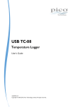
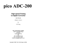
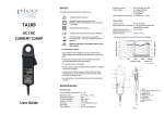
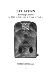
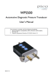
TA058
50 MHz ±700 V Differential Probe
User’s Manual
This probe complies with IEC-1010.1, IEC-1010.2-031 CAT I or CAT II,
Pollution Degree 2.
1. Safety terms and symbols
Issue history:
1
Terms appearing in this manual:
28.8.2008.
Pico Technology
WARNING
Warning statements identify conditions or practices
that could result in injury or death.
CAUTION
Caution statements identify conditions or practices
that could result in damage to this product or other
property.
James House
Colmworth Business Park
Symbols appearing on the product:
St. Neots
PE19 8YP
www.picotech.com
Danger
High Voltage
Protective
(Earth) Terminal
Attention
Refer to Manual
Lemo®, Probus® and Pico Technology are registered trademarks.
Manufactured in Republic of China.
8
© Copyright Pico Technology 2008
DO144-1
DO144-1
© Copyright Pico Technology 2008
1
2. General safety summary
9. Derating curve
Please review the following safety precautions to avoid injury and prevent damage
to this probe or any products that are connected to it.
The derating curve for absolute maximum input voltage is as follows:
Observe maximum working voltage
Voltage (V RMS)
To avoid any injury, do not use the probe when the voltage between either input
lead and earth is above 600 V RMS CAT I.
Must be grounded
This probe is grounded with the shell of the BNC connector and an auxiliary
grounding terminal.
WARNING
Before making connections to the input leads of this
probe, ensure that its output lead is grounded. You
may do this either by connecting the BNC shell to a
grounded
measurement
instrument,
or
by
connecting the auxiliary grounding terminal to a
reliable ground point. Read the next paragraph for
further advice.
You must verify that the probe is securely grounded before connecting the probe
input leads. Some types of measuring instrument, such as a USB oscilloscope
connected to a laptop, are unlikely to be grounded even if the laptop is powered
from the mains. Bench-top oscilloscopes are usually grounded, but in some cases
may have been isolated from ground. A USB oscilloscope connected to a desktop
computer is usually grounded. In any case, do not assume that the measurement
instrument is grounded. Always verify the ground connection for yourself
before connecting the probe input leads.
Use fused test prods if necessary
If this probe is intended to use for measurements in circuits of INSTALLATION
CATEGORY III, it should incorporate with fused test prods.
1000
600
600
100
20
10
1
1.E+06
1.E+07
Frequency (Hz)
10. Test procedure
a.
b.
c.
d.
e.
Connect the BNC output connector to the vertical input of a general-purpose
oscilloscope.
Connect an appropriate power source to this probe and then turn it on.
Set the oscilloscope input coupling to DC and 1 V/div. Center the trace on the
display.
Connect the inputs of the probe to power lines.
A 50 Hz / 60 Hz sine-wave of proper amplitude will be displayed on the screen
of the oscilloscope. This means the probe is working properly.
Do not operate without covers
11. Cleaning
To avoid electric shock or fire hazard, do not operate this probe with the covers
removed.
Use a soft cloth to clean the probe, taking care not to cause damage.
Do not operate in wet or damp conditions
1.E+08
a.
b.
c.
Do not immerse the probe.
Do not use abrasive cleaners.
Do not use chemicals contains benzene or similar solvents.
To avoid electric shock, do not operate this probe in wet or damp conditions.
Do not operate in explosive atmosphere
To avoid injury or fire hazard, do not operate this probe in an explosive atmosphere.
Avoid exposed circuitry
To avoid injury, remove jewelry such as rings, watches and other metallic objects.
Do not touch exposed connections and components when power is present.
2
© Copyright Pico Technology 2008
DO144-1
DO144-1
© Copyright Pico Technology 2008
7
8. Specifications
Use proper power source
Bandwidth
DC to 50 MHz (-3 dB)
Attenuation ratio
1:10
Accuracy
±1%
Rise time
< 7 ns
Input impedance
1.6 MΩ || 7 pF each side to ground
Input Voltage
Differential Range*
±70 V (DC + Peak AC) or 70 V RMS
Common Mode Range*
±700V (DC + Peak AC) or 600 V RMS
Absolute Max. Voltage*
±700 V (DC + Peak AC) or 600 V RMS CAT I
(either input to ground)
Output
Swing (into 5 kΩ load)
±7 V
Offset (typical)
< ±2 mV
Noise (typical)
0.7 mV RMS
Source impedance (typical)
50 Ω
CMRR (typical)
-95 dB @ 60 Hz; -60 dB @ 1 MHz
Ambient operating temperature -10 to +40 °C
Ambient storage temperature
-30 to +70 °C
Ambient operating humidity
25 to 85% RH
Ambient storage humidity
25 to 85% RH
Power requirements**
Option 1
Mains adaptor (6 V DC 90 mA or 9 V DC 70 mA)
Option 2
Removable battery pack (4xAA cells)
Option 3
Power leads
Optional extension plugs for mains adaptor
- Input
One jack with 1 A current rating
- Output
Three plugs with 1 A current rating
Length of input leads
50 cm
Length of BNC cable
125 cm
Weight
300 g
Dimension (LxWxH)
111 mm x 22 mm x 14 mm
To ensure proper functioning of this probe, use four AA cells or a 6 V DC / 90 mA
mains adaptor or 9 V DC / 70 mA mains adaptor or power leads.
Do not operate the probe if it is damaged
If you suspect there is damage to this probe, have it inspected by qualified service
personnel.
3. Description
By enabling conventional oscilloscopes to display and measure in-circuit waveforms
that are referenced to high common-mode voltages, this differential probe extends
the measurement capability of oscilloscopes to electronic power converters,
inverters, motor speed controls, switch-mode power supplies and many other
applications.
4. Installation
a.
b.
Simply plug in the BNC output connector to the vertical input of a
general-purpose oscilloscope or other measurement instrument, and connect
the auxiliary grounding terminal to a proper ground.
The measurement
instrument must have a ground reference.
Connect an appropriate power source (mains adaptor, battery pack or power
lead) to this probe and then turn it on.
WARNING
c.
To protect against electric shock, use only the
accessories designed for use with this differential
probe.
Using the appropriate probe accessories, connect the input to the circuits under
measurement.
CAUTION
This probe is designed for carrying out
measurements between two points on
under test.
It is not intended for
insulating the circuit under test and the
instrument.
differential
the circuit
electrically
measuring
* Voltage limit is the lesser of the DC+Peak AC and RMS values.
**
a. The supplied voltage must be less than 16 V and greater than 3.3 V, otherwise
the probe could be damaged or might not operate properly.
b. Polarity is “+” inside and “–” outside. If the polarity is wrong, a built-in circuit
protects the probe so that no danger or damage will occur.
c. When the voltage of the cells becomes too low, the power indicator on the
panel will flicker.
6
© Copyright Pico Technology 2008
DO144-1
DO144-1
© Copyright Pico Technology 2008
3
5. Appearance
6. Power leads
The differential probe looks like this:
Two types of power leads are available for use with this instrument:
a.
b.
d
b
c
Lemo® Lead: For oscilloscopes with Lemo® power connectors.
Probus® Lead: For oscilloscopes with Probus® power connectors.
a
Power Lead
e
f
g
Oscilloscope front panel
a.
Output Cable: The BNC output connector and an auxiliary grounding terminal
are connected to the oscilloscope.
b.
Removable Battery Pack (optional): 4 x AA cells
c.
Power Source Connector. This can be connected to the following sources:
- Mains adaptor (6 V DC / 90 mA or 9 V DC / 70 mA)
7. Removable Battery Pack
The following figure illustrates the operation of the removable battery pack;
- Removable battery pack (4 x AA cells)
- Power leads
d.
Power Supply
e.
Probe Body
f.
The input leads of the differential probe
g.
Sprung Hooks.
circuits.
4
The sprung hooks are connected safely to test points in
© Copyright Pico Technology 2008
DO144-1
DO144-1
© Copyright Pico Technology 2008
5