1
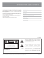
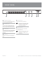
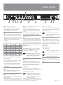
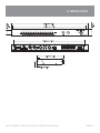
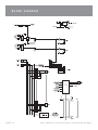
ZONER16
1 6 ZO N E PAGI N G AN D BGM S W I T C H ER
INS TA LLAT I ON AN D OP E RAT I ON M AN UAL
I M P O RTA N T SAF E TY INF ORMATION
1.
Save the carton and packing material even if the equipment has
arrived in good condition. Should you ever need to ship the unit, use
only the original factory packing.
2.
Read all documentation before operating your equipment. Retain
all documentation for future reference.
3.
Follow all instructions printed on unit chassis for proper operation.
4.
Do not spill water or other liquids into or on the unit, or operate
the unit while standing in liquid.
5.
Make sure power outlets conform to the power requirements listed
on the back of the unit.
6.
Do not use the unit if the electrical power cord is frayed or broken.
The power supply cords should be routed so that they are not likely
to be walked on or pinched by items placed upon or against them,
paying particular attention to cords and plugs, convenience
receptacles, and the point where they exit from the appliance.
7.
8.
9.
Always operate the unit with the AC ground wire connected to the
electrical system ground. Precautions should be taken so that the
means of grounding of a piece of equipment is not defeated.
13. Do not block fan intake or exhaust ports. Do not operate equipment
on a surface or in an environment which may impede the normal flow
of air around the unit, such as a bed, rug, weathersheet, carpet,
or completely enclosed rack. If the unit is used in an extremely dusty
or smoky environment, the unit should be periodically “blown free”
of foreign matter.
14. Do not remove the cover. Removing the cover will expose you
to potentially dangerous voltages. There are no user serviceable
parts inside.
15. Do not drive the inputs with a signal level greater than that required
to drive equipment to full output.
16. Do not connect the inputs / outputs of amplifiers or consoles to any
other voltage source, such as a battery, mains source, or power supply,
regardless of whether the amplifier or console is turned on or off.
17. Do not run the output of any amplifier channel back into another
channel’s input. Do not parallel- or series-connect an amplifier output
with any other amplifier output. Australian Monitor Inc is not
responsible for damage to loudspeakers for any reason.
18. Do not ground any red (“hot”) terminal. Never connect a “hot” (red)
output to ground or to another “hot” (red) output!
Mains voltage must be correct and the same as that printed on the
rear of the unit. Damage caused by connection to improper AC voltage
is not covered by any warranty.
19. Non-use periods. The power cord of equipment should be unplugged
from the outlet when left unused for a long period of time.
Have gain controls on amplifiers turned down during power-up
to prevent speaker damage if there are high signal levels at the inputs.
20. Service Information Equipment should be serviced by qualified service
personnel when:
10 Power down & disconnect units from mains voltage before making
connections.
A. The power supply cord or the plug has been damaged.
B.
Objects have fallen, or liquid has been spilled into the equipment
11. Never hold a power switch in the “ON” position if it won’t stay
there itself!
C. The equipment has been exposed to rain
12. Do not use the unit near stoves, heat registers, radiators, or other heat
producing devices.
D. The equipment does not appear to operate normally, or exhibits a marked
change in performance
E. The equipment has been dropped, or the enclosure damaged.
THIS SAFETY INFORMATION IS OF A GENERAL NATURE AND MAY BE SUPERSEDED BY INSTRUCTIONS CONTAINED WITHIN THIS MANUAL
INTRODUCTION AND CONTENTS
The Zoner 16 is the entry level AMIS zoning product. A simple 16 zone output
switcher with much more - providing remote paging facility, zone BGM enable
buttons, LED BGM indication per active zone, zone output relays and separate
BGM and paging inputs.
I NT RODUCT I ON
1
F RONT PANE L
2
The Zoner 16 provides support for one 16 zone remote paging station, as well
as one “All Call” priority paging input with contact closure logic triggering to
route the priority paging inout to all zones.
RE AR PANE L
3
I NSTAL L AT I ON & T ROUBL E SHOOT I NG
4
DI ME NSI ONS
5
BL OCK DI AGRAM
6
SP E CI F I CAT I ONS
7
The Zoner 16 make multiple zone BGM selection and remote multiple zone
paging a simple task indeed.
Thank you for purchasing the Australian Monitor Zoner 16.
AUS, EUR, USA
Rev A 30/03/07
This symbol is intended to alert the user to the presence
of uninsulated “dangerous voltage” within the products
enclosure that may be of sufficient magnitude to constitute
a risk of electric shock to persons.
CAUTION
RISK OF ELECTRIC SHOCK
DO NOT OPEN
CAUTION: TO REDUCE THE RISK OF ELECTRIC SHOCK,
This symbol is intended to alert the user to the presence
of important operational and maintenance (servicing)
instructions in the literature accompanying the appliance.
DO NOT REMOVE COVER (OR BACK),
NO USER SERVICEABLE PARTS INSIDE,
REFER SERVICING TO QUALIFIED SERVICE PERSONAL.
Caution:
WARNING!
TO REDUCE THE RISK OF FIRE OR ELECTRIC HOCK
To prevent electric shock do not use this (polarised) plug
with an extension cord, receptacle or other outlet unless
the blades can be fully inserted to prevent blade exposure.
To prevent electric shock, match wide blade of plug to wide
slot, fully insert.
DO NOT EXPOSE THIS EQUIPMENT TO RAIN OR MOISTURE.
A M I S Z O N E R 1 6 I N S TA L L AT I O N & O P E R AT I O N M A N U A L
PA G E 3
F R O N T PA N E L
1
1
BGM ON/OFF SWITCH
These switches turn the BGM amplifier input ON or
OFF to the corresponding ZONE OUTPUT
2
PAGING LEVEL
This pot controls the level of the XLR output signal
of the PAGING channel. It affects both the Paging
Station and the Mic/Line XLR & RCA priority
paging input.
4
5
3
4
5
5
POWER LED ON
This LED indicates the unit is powered “on”.
NOTE: When using the 24VDC in socket,
the amplifier is ‘on’ and the power LED
will always be on regardless of the
position of the power switch.
BGM ON/OFF LED
These LED’s indicate if the BGM amplifer input is
routed to the corresponding ZONE OUTPUT. Label
space is provided to write the name of each zone.
3
2
6
POWER SWITCH
This switch switches power on or off from the
mains. The up position is on.
NOTE: When using the 24VDC in socket,
the amplifier is ‘on’ regardless of the
switch position.
BGM LEVEL
This controls the overall level of the background
music.
PA G E 4
A M I S Z O N E R 1 6 I N S TA L L AT I O N & O P E R AT I O N M A N U A L
R E A R PA N E L
10
9
10
8
7
6
BGM and PAGING IN
1
5
These pluggable terminal blocks connect the
speaker outputs of the amplifiers used for the
PAGING and BGM sources respectively.
ZONE LOGIC OUT
2
This 25pin D-connector is used to control external
devices. They can be used to drive relays for attenuator bypass. The outputs are open collector pull up,
24V 100mA drive. The total drive capacity is 150mA.
This table shows an example of the possible
combinations.
Number of relays per zone
Zone 1 Zone 2 Zone 3 Zone 4 Zone 5 Zone 6
4
4
3
3
3
2
2
2
1
2
1
3
2
1
2
2
1
1
1
1
1
2
1
1
1
5
6
1
1
1
The PAGING OUT XLR provides balanced line level
signal. The level of this output is set by the PAGING
LEVEL control on the front panel. Both the XLR/RCA
PRIORITY PAGING INPUT and the PAGING STATION
INPUT are mix to this output. The PRIORITY PAGING
INPUT has priority over the remote PAGING
STATION INPUT.
6 ) is to be connected to a
paging amplifier. The paging amplifier output is to be
connected to the PAGING IN connector ( 1 )
1
1
3
8
2
1
24VDC SOCKET
This 2.1mm x 5.5mm barrel socket is provided for
24V emergency systems and is not switched by the
front panel power switch.
NOTE: The 24VDC socket does not
provide trickle charge facility. Tip of the
connector is positive.
PAGING OUT
The PAGING OUTPUT (
1
9
IEC MAINS INPUT SOCKET
This is a standard IEC 3 pin socket. It accepts a
standard IEC mains cable, provided. The fuse draw
contains the mains fuse and a spare. The mains
fuse is a time lag (slow blow) HRC 20mm x 5mm
ceramic type fuse.
The ratings are:
230V/240V model 63mA
115V model 120mA
IMPORTANT: Always replace the fuse with
one of the same value and type.
NOTE: When wiring the LINE output as
unbalanced, Pin2 should be wired as hot
and Pin1 should be wired as ground/
shield. Do not wire Pin3.
1
If more attenuator drive is required use an external
drive box is required with more power.
The pins of the D-connector correspond to each
zone (e.g. Pin 3 is for Zone 3). Pins 17-25 are
common ground.
ZONE OUTPUTS
These pluggable terminal blocks connect to the
speaker runs for each respective zone.
4
BGM and PRIORITY PAGING INPUTS
Both these channels have two inputs:
XLR input - This is a balanced input. It accepts mic
or line level signals depending on the gain switch
position.
RCA input - This is an unbalanced line level input. The
two RCA sockets are summed to mono internally.
This is based on the attenuators sold by Australian
Monitor. Other manufactures may have different
drive requirements.
3
4
PAGING STATION INPUT
This RJ45 socket accepts the CAT5 cable from the
PAGING STATION.
NOTE: Always disconnect power to the
Zoner 16 before replacing fuses.
10
7
BGM OUT
The BGM OUT XLR provides balanced line level
signal. The level of this output is set by the BGM
LEVEL control on the front panel. This output is not
affected by the PRIORITY PAGING or PAGING
STATION INPUT.
OPTIONAL MODULE INPUTS
This socket is used with a tone module and/or VCA
module.
The BGM OUT ( 7 ) is to be connected to a BGM
amplifier. The BGM amplifier output is to be connected
to the BGM IN connector ( 1 )
NOTE: When wiring the LINE output as
unbalanced, Pin2 should be wired as hot
and Pin1 should be wired as ground/
shield. Do not wire Pin3.
A M I S Z O N E R 1 6 I N S TA L L AT I O N & O P E R AT I O N M A N U A L
PA G E 5
I N S TA L AT I O N E X A M P L E
PA G E 6
A M I S Z O N E R 1 6 I N S TA L L AT I O N & O P E R AT I O N M A N U A L
INTERNAL ADJUSTMENTS &
I N S TA L L AT I O N / T R O U B L E S H O O T I N G
The only internal access required is for the installation of an Australian Monitor tone generator module. Installation is easy and is done by inserting the module
onto the appropriate headers.
INPUT CONNECTIONS
For wiring balanced in, pin 2 is hot. Balanced input wiring (shielded pair cable) is recommended.
Unbalanced RCA wiring should be keep as short as possible. Typically less than 3m.
TRO UBL E S HOOT IN G GU I D E
TROUBLE
LIKELY CAUSE
REMEDY
Power LED not on
Power not reaching unit
Check mains connection
Check mains fuse
Check power switch is on
Distorted sound
Output is being over driven
Reduce output volume
No sound but amp is on
Volume controls down
Check volume controls
A M I S Z O N E R 1 6 I N S TA L L AT I O N & O P E R AT I O N M A N U A L
PA G E 7
Z 1 6 M PA G I N G S TAT I O N
INTRODUCTION
CONTROLS
The Australian Monitor Installation Series Zoner16M Paging Station is a 16 zone
paging station complete with a slimline gooseneck paging microphone. The Paging
station is designed to be used with the Zoner16 Zone Switching System and will
allow paging into any individual zone, any combination of zones or All Call to all
zones. LED indicators provide the user with visual feedback of the zones being
paged or if the priority local paging All Call is busy. Ample label space is provided
on the paging station. Connection to the Zoner16 is via low cost CAT 5 cable and
as with all Australian Monitor installation products the paging
station provides an elegant solution at a contractor friendly price.
5
2
3
4
1
1
ZONE SELECT
These buttons allow selection of zones for paging.
When selected, the adjacent LED glows green.
Pressing the button again deselects the zone. The
area next to the button is for labelling the zone.
Selecting a zone does not instigate paging.
See 4. ZONE PAGE.
2
3
ALL PAGE
This button pages to all zones. It is momentary so
must be held while talking into the microphone. It
activates the microphone and mutes the program
sources. It does NOT clear the current zone selection configuration so the paging station will return
to its previous state (selected zones) once the ALL
PAGE button is released.
5
PAGING ACTIVE
This LED glows when the paging station is being
used (you are making a page). It flashes when the
main unit priority All Call is being used. Paging is
not possible while this is flashing, however zone
selections can still be made.
CLEAR
This button clears all the selected zones.
4
ZONE PAGE
This button pages to the current zone selection
configuration as indicated by the ZONE select
LED’s. The zones being paged have their BGM
sources muted and the microphone becomes
active.
INSTALLATION AND SETUP
The CAT5 cable connects to the RJ45 socket on the rear panel of the paging station. This socket is a NEUTRIKTM connector designed to be used with the XLR
style housing (model NE8MC) to improve reliability. Normal RJ45 connectors can also be used.
Plugging and unplugging the cable while the system is powered up may result in the system locking up and is not recommended. If this should happen, reset the
Zoner16 by switching off, then on.
GAIN
To accommodate different speech levels, there is a gain control on the base of the Zoner16M. This control ships set
to minimum and may be adjusted to suit. Increasing this control too far may cause the paging station to distort if
loud or close speech levels are encountered.
PA G E 8
A M I S Z O N E R 1 6 I N S TA L L AT I O N & O P E R AT I O N M A N U A L
DIMENSIONS
A M I S Z O N E R 1 6 I N S TA L L AT I O N & O P E R AT I O N M A N U A L
PA G E 9
BLOCK DIAGRAM
PA G E 1 0
A M I S Z O N E R 1 6 I N S TA L L AT I O N & O P E R AT I O N M A N U A L
S P E C I F I C AT I O N S
FREQUENCY RESPONSE
20Hz - 20kHz (+0,-3dB)
TOTAL HARMONIC DISTORTION
< 0.1% @ 1kHz
SIGNAL TO NOISE RATIO
> 90dB (all pots at centre position)
CROSSTALK BETWEEN CHANNELS
>70dB
SENSITIVITY (TRIM IN CENTRE 0 dB)
Line Sens 0.775V, 0dBu Imp >100k
RCA 200mV, -12dBu Imp 30kohm
MAX LEVEL IN
XLR mic -9dBu line >30dBu
RCA >30dBu
MAX LEVEL OUT
+27dBu
MAX AMPLIFIER POWER INPUT
100V, 500W
70V, 350W
4Ω, 100W
OUTPUTS
Nominal Level 0dBu into 1kohm
Imp 100ohm
ZONE LOGIC OUTPUT DRIVE
POWER INPUT
150MA (24V)
AC: 230V/50Hz or 115V/60Hz, 3 pin IEC320-C14 connector
POWER CONSUMPTION (MAX)
15 VA
FUSES
MAINS (115V)
MAINS (230V)
DIMENSIONS HXWXD
WEIGHT
A M I S Z O N E R 1 6 I N S TA L L AT I O N & O P E R AT I O N M A N U A L
120mA
63mA
90mm x 505mm x 270mm (3.5“x19.9”x10.6”)
Net 2.8kg (6.2lb)
Shipping 3.8kg (8.4lb)
PA G E 1 1
AUSTRALIA AND NEW ZEALAND
w w w. a u s t r a l i a n m o n i t o r. c o m . a u
SYDNEY
MELBOURNE
BRISBANE
ADELAIDE
PERTH
AUCKLAND
(NSW & ACT SALES)
(VIC & TAS SALES)
(QLD SALES)
(SA & NT SALES)
(WA SALES)
(NZ SALES)
1 Clyde Street
Silverwater
NSW 2128
Private Bag 149
Silverwater NSW 1811
Phone: (02) 9647 1411
Fax: (02) 9648 3698
Email:
[email protected]
22/277
Middleborough Road
Box Hill VIC 3128
PO Box 151 Blackburn
South VIC 3130
Phone: (03) 9890 7477
Fax: (03) 9890 7977
Email:
[email protected]
42 Commercial Road
Fortitude Valley
QLD 4006
PO Box 871 Fortitude
Valley QLD 4006
Phone: (07) 3852 1312
Fax: (07) 3252 1237
Email:
[email protected]
31 Walsh Street
Thebarton
SA 5031
PO Box 157
Hindmarsh SA 5007
Phone: (08) 8352 4444
Fax: (08) 8352 4488
Email:
[email protected]
3/11 Howe Street
Osborne Park WA 6017
PO Box 1281
Osborne Park BC
WA 6916
Phone: (08) 9228 4222
Fax: (08) 9228 4233
Email:
[email protected]
9C Piermark Drive
Albany 0752
New Zealand
PO Box 300-512
Albany 0752
Phone: (09) 415 9426
Fax: (09) 415 9864
Email:
[email protected]
EUROPE / ASIA / MIDDLE EAST
w w w. a u s t r a l i a n m o n i t o r. c o m . a u
INTERNATIONAL SALES
1 Clyde Street Silverwater NSW 2128 Australia
Private Bag 149 Silverwater NSW 1811
Phone: (02) 9647 1411
Fax: (02) 9648 3698
Email: [email protected]