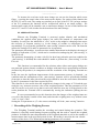
1
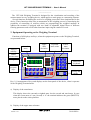
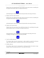
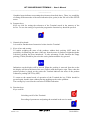
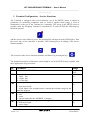
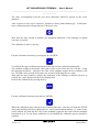
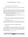
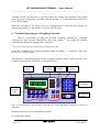
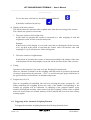
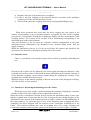
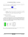
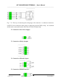
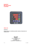
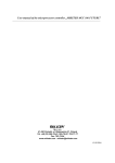
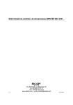
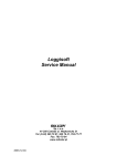
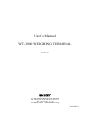
User’s Manual
WT-3000 WEIGHING TERMINAL
Version 1.21
Sp. z o.o. (L.L.C.)
41 - 250 Czeladź ul. Wojkowicka 21, POLAND
Tel. +48 (32) 265-76-41; 265-70-97; 763-77-77
Fax: +48 (32) 763 – 75 – 94
www.mikster.com.pl
[email protected]
30.09.2002 r.
WT-3000 WEIGHING TERMINAL - User’s Manual
___________________________________________________________________________
______________
Contents:
1.
2.
3.
4.
5.
6.
7.
8.
9.
Description of the Device........................................................................................ 2
Equipment Operating as the Weighing Terminal............................................
2
Equipment Configuration – Service Functions .................................................... 5
3.1 Setting of the Transmission Data Parameters RS485............................................. 8
3.2 Calibration of the Weighing Terminal.................................................................... 8
3.3 Setting of Parameters of the Applied Strain Gauges............................................ 10
3.4 Setting of Default Parameters… ...................................................................
10
Setting of the Measuring Circuit of the Weighing Terminal.. .....................
10
4.1 Digital Filters ..................................................................................................... 10
4.2 Functions Improving the Readout Stability ........................................................... 13
4.3 Functions Increasing the Read Rate .............................................................
14
4.4 Additional Functions ............................................................................................ 14
Recording of the Weighing Process..................................................................... 14
5.1 Automatic Recording ...................................................................................
15
5.2 Manually Triggered Recording ........................................................................... 16
Terminal Operating as a Weighing Controller .................................................
16
6.1 Triggering of an Automatic Weighing Function ................................................ 19
6.2 Manual Control..............................................................................................
19
6.3 Function of the Intelligent Switching-off of the Feeder......................................... 19
Connection of the Device ....................................................................................... 20
7.1 Connection of the Strain Gauge Bridge ................................................................. 20
7.2 Connection of the Power Supply............................................................................. 21
7.3 Connection of Relay Outputs.. .....................................................................
21
7.4 Connection of Bistable Inputs ........................................................................
21
7.5 Connection of the RS485 interface......................................................................... 21
Signaling of Device Errors. ..........................................................................
22
Technical Parameters ......................................................................................... 22
1. Description of the Device
Version 1.21
1
30.09.2002 r.
WT-3000 WEIGHING TERMINAL - User’s Manual
___________________________________________________________________________
______________
The WT-3000 Weighing Terminal is designed for the visualization and recording of the
measurements in every weighing device, which applies a strain gauge as a measuring element.
Several functions facilitating the work of a weighing person have been implemented in the
device. Those functions allow also an automation of the weighing process by introducing the
possibility of controlling of rectifiers which are proportioning the weighted medium. In
addition the terminal is equipped with two kinds of adjustable digital filters of different
filtering parameters and several other functions improving the comfort of work.
2. Equipment Operating as the Weighing Terminal
Functions of all displays and keys, when the equipment operates as the Weighing Terminal,
are presented below:
Lack of
stability
Actual
mass
Upper
mass
deviation
Expected
mass value
Lower
mass
deviation
Stable
measurement
Bargraf
Numerical
keyboard
P1..P10
program
keys
Zeroing and
taring
Rys.:2.1 Arrangement of keys and displays on the front panel of the device, when it operates
in the Weighing Terminal mode.
a) Display of the actual mass:
This display shows the currently weighted mass less the zeroed and tared mass. In case
when the recent mass of a tare (zeroed) is “0” the terminal indicates the gross (BRUTTO)
mass placed on the scales platform.
b) Display of the upper mass tolerance:
Version 1.21
2
30.09.2002 r.
WT-3000 WEIGHING TERMINAL - User’s Manual
___________________________________________________________________________
______________
Display shows the maximal declared mass tolerance taken into account at controlling the
bar-graph and the stability diode. Pressing the function key:
and introducing the value from the numerical keyboard does the setting of tolerance.
c) Display of the lower mass tolerance:
Display shows the minimal declared mass tolerance taken into account at controlling the
bar-graph and the stability diode. Pressing the function key:
and introducing the value from the numerical keyboard does the setting of tolerance.
d) Display of the expected mass:
Display shows the expected mass from which the tolerances for controlling the bar-graph
and the stability diode are calculated. Pressing the function key:
and introducing the value from the numerical keyboard does the setting of the value.
All changes of setting are confirmed by the key ENTER:
e) Lack of a stability indicator:
The indicator lights when the measurement is either unstable or outside the tolerances
range. That indicator may be switched-off in the F05 cell of the SETUP menu.
f) Stability indicator:
The indicator lights when the measurement is stable and within the tolerances range.
Stability criteria are determined in the F15 cell of the SETUP menu.
g) Bar-graph:
Version 1.21
3
30.09.2002 r.
WT-3000 WEIGHING TERMINAL - User’s Manual
___________________________________________________________________________
______________
Graphical mass indicator concerning the tolerances described above. There is a possibility
of setting different modes of the mass indication (line, point) in the F06 cell of the SETUP
menu.
h) Program keys:
Keys are used for setting the tolerances of the Terminal stored in the memory of the
device. To save the setting of a particular program the function key should be pressed:
i) Numerical keyboard:
It is used for introduction of numerical values into the Terminal.
j) Keys of tare and zeroing:
To enable weighing the mass of the products without their packing (NET mass) the
possibility of subtracting the mass of the tare from the mass of products weighted together
with their packing has been introduced. To take advantage of this function the empty
packing (TARA) should be placed on the scales platform and the key pressed:
Indications on the display will be zeroed. When the packing is removed from the scales
the display will show the mass of the tare (TARA) with the negative sign. Thus, when the
packed product is placed on the scales the Terminal indicates the mass of the product
without its packing (NETTO) (NET).
To return to the normal mode of operation of the Terminal the key TARA should be
pressed again, but this time without placing anything on the scales platform.
The zeroing key is used for the correction of ZERO indication.
k) Function keys:
Keys used for:
Switching on/off of the Terminal:
Recording of parameters and putting the terminal in the service mode:
Version 1.21
4
30.09.2002 r.
WT-3000 WEIGHING TERMINAL - User’s Manual
___________________________________________________________________________
______________
3. Terminal Configuration – Service Functions
The Terminal is equipped with several functions (set in the SETUP menu) to adjust its
parameters for measuring conditions such as: kind of applied strain gauge, a level of
disturbances or the use of the Terminal as a controller. The access to the SETUP menu is
possible when the Weighing Terminal is switched-off. To enter SETUP the following key
should be pressed:
and the serwice code (002010) given. The lettering F00 will appear on the LED display. Then
the access into service functions is possible. The following keys do editing of the service
function number:
The selection of the service function should be confirmed by pressing the key:
.
The detailed description of functions, which might be set in the SETUP menu, together with
their applications are given below:
No.
F00
Parameter
Range
Address in the MODBUS network
F01
Transmission rate
1 – 9600 bps
2 – 19200 bps
4 – 115200 bps
Permission of the red diode control
1..245
(247)
0..4
(1)
F05
F06
F07
0, 1
(0)
0 – non-active diode
1 – diode lights if the weighted mass is outside the tolerance range for the
particular program
The way of diode line control
0 – line
1 – point
2 – special setting for the ‘MORPOL’ Company
Login permission for the person servicing the Terminal
0 – non-active login
1 – active login
Version 1.21
5
0..2
(0)
0, 1
(0)
30.09.2002 r.
WT-3000 WEIGHING TERMINAL - User’s Manual
___________________________________________________________________________
______________
F08
F09
F10
F11
F12
F13
F14
F15
F16
Going-out of the set program values
The parameter determines time duration (in seconds) between the moment
of the last pressing of the program selection key and the moment when the
indications of the mass and tolerances set for the particular program are
automatically blanking out.
Recording release
0 – non-active recording of weighing
1 – automatically triggered recording (the last stable readout is recorded)
2 – edge triggered recording at the bi-stable output DI1
Filter inertia
This parameter determines the filtration degree of the measurement in case
of the high level of disturbances in the mass determination.
Refresh period of the mass indication at the stable readout
The parameter determines the period of time (n*0.05 s) after which a new
mass value is displayed. This parameter is sensitive when no abrupt
changes in the mass value occur.
Refresh period of the mass indication at the non-stable readout
The parameter determines the period of time (n*0.05 s) after which a new
mass value is displayed. On the basis of this parameter the actualization of
readout occurs regardless of the stability or abrupt change of the mass.
Sensitivity of the system of the fast mass indication
This parameter determines the non-dimensional level of the mass change
at which the integrating filter set-up in the F19 cell is reset. After the reset
the measurement result corresponds to the actually weighted mass while
the time needed for stabilizing the results is much shorter.
The level of tare control (TARA)
The parameter determines the mass range (in 0.1g units) liable to an autozeroing function. This function allows to eliminate an influence of
surroundings such as: temperature, humidity, hysteresis of the strain gauge
and small changes in the real tare - on the level of zero set by the ZERO
and TARA keys. The „0” value of that parameter switches-off the autozeroing function.
Sensitivity of the „freezing” system of the mass indication
The parameter determines how large must be the mass change to cause
‘freezing’ of its indication – as determined by the F17 parameter. Small
values of this parameter cause the ’freezing’ at small mass fluctuations
while large values cause switching-off of the ‘freezing’ system.
Duration of the ‘freezing’ of the indication after a large mass change.
The parameter determines for how long (n*0.05 s) the display of the
indication is ’freeze’ (no change in the display), in case of an abrupt
change of the strain gauge load (above 1% of the measuring range).
Version 1.21
6
0..240
(5)
0..2
(0)
1..24
(1)
2..50
(2)
2..50
(2)
0...9999
(1000)
0..250
(0)
2..5000
(500)
2..50
(2)
30.09.2002 r.
WT-3000 WEIGHING TERMINAL - User’s Manual
___________________________________________________________________________
______________
F17
F18
F19
F20
F21
F22
F23
F24
F25
F26
F30
F31
F32
F35
F36
F40
F41
Duration of the ‘freezing’ of the indication after small mass
fluctuations.
The parameter determines for how long (n*0.05 s) the display of the
indication is ’freeze’ (no change in the display) in case when an abrupt
change of the strain gauge load is higher than the value determined by the
F15 parameter.
Hysteresis of the mass display
The value of this cell determines the hysteresis of the mass indicator
readout – expressed in values corresponding to 0.1 of the graduation. This
function eliminates fluctuations of the mass indication when the result is at
the threshold of two values.
Magnitude of the table for calculating the measurement integral
The function determines the averaging level of the integrating filter.
Value „1” means a resignation from any integration of the measurement,
while other numbers determine the length of integration periods in n*
0.005s units (e.g. the value “100” corresponds to 0.5s of integration).
Real-time clock - year
Real-time clock - month
Real-time clock –day
Real-time clock – hour
Real-time clock – minute
Real-time clock – second
Time taken into account in the zeroing function
The parameter determines time n*0.05s during which the Terminal
controls the value of the indicator tare (TARA). When the readout is stable
and the results are within the limits estimated in the F14 cell the Terminal
corrects the tare value saved in its memory.
Test of the analogue to digital converter
This cell displays an average noise background and interference value
caused by the scales (it means the level of scales platform vibrations, the
level of industrial interference) as well as the readout in the sixteen bit
code of the analogue to digital converter.
Test of the register memory
0- test done properly
Test of the bistable inputs
The function indicates the state of bistable inputs of the terminal.
Deleting of the register memory
Writing „ 0” deletes the register memory.
Recovery of the default values of the configuration parameters (the
SETUP menu values are given in parenthesis)
Calibration – zero
Calibration – mass
Version 1.21
7
2.50
(2)
0..10
(1)
1..200
(50)
1..20
(10)
30.09.2002 r.
WT-3000 WEIGHING TERMINAL - User’s Manual
___________________________________________________________________________
______________
F42
F43
F44
F45
F50
F51
Rough tare
This function allows an electrical correction of the strain gauge preload
caused by the elements of the measuring system. This cell value is
determined by the voltage being added to the voltage of the strain gauge
bridge before feeding it to the A to D converter.
Hysteresis level of the automatic weighing counter
The function describes the percentage value of the deflection from the
lower edge of the set proper weight above which the measurement is
recorded.
Precision of the mass display
The function allows to set an order of the displayed mass by changing the
placement of the decimal point in the displayed result. This parameter
should be set before the calibration of the Weighing Terminal.
Setting of the precision of the mass display
This parameter decides if:
1- The mass counter counts the mass with the accuracy set in F44
0- The mass counter counts the mass displayed in front of the decimal
point.
This function is only available in the controller mode of operation.
Mode of operation of the Terminal
0- Terminal operates as a scales,
1- Terminal operates as a controller of automatic weighing.
Stabilization time for an automatic weighing
The parameter determines the time (in seconds) elapsing from the moment
when the rectifier was switched off to the moment of the stabilization of
the mass measurement. This function may be utilized in the controller
mode of operation.
0..63
0..99
(10)
0..3
(0)
0..1
(0)
0..1
(0)
1..25
(10)
TABLE 3.1 List of configuration parameters
3.1 Setting of the Transmission Data Parameters (RS485)
Cells F00 and F01 are used for the setting of interface transmission parameters RS485. In
those cells the address in the MODBUS network as well as the transmission rate are set
(according to the TABLE 1).
3.2 Calibration of the Weighing Terminal
The Terminal should be switched on at least 60 minutes before the calibration process to
stabilize the temperature inside the device.
Enter the SETUP menu and set the following parameters:
F10 – 24,
F13 – 9999,
F15 – 5000,
F19 – 200,
F44 – required number of digits, after the decimal point, in the displayed mass indication,
Version 1.21
8
30.09.2002 r.
WT-3000 WEIGHING TERMINAL - User’s Manual
___________________________________________________________________________
______________
The mass corresponding with the zero mass indication should be placed on the scales
platform.
After selection of the service function: „kalibracja: dolny punkt kalibracyjny” (Calibration,
lower calibration point) (Setup function, F40) press a key:
Wait until the time needed to stabilize the displayed indication of the analogue to digital
converter is reached.
The calibration is done by the key:
Exit the calibration function by pressing the key ENTER:
To calibrate the upper calibration point the following activities should be undertaken::
The standard weight of the known value place on the scales. Enter the F41 cell and – using
the numerical keyboard – introduce the value of the standard weight (do not confirm by the
key ENTER). Next proceed in the same way as when calibrating the zero value:
Wait until the time needed to stabilize the indication of the analogue to digital converter is
reached (the value displayed in the lower display unit).
Perform the calibration by pressing the key:
Exit the calibration function using the key ENTER:
When the calibration process has been successfully done then - after the exit from the SETUP
menu and switching-off the weighting device - the Terminal should indicate „0” value for the
scales without any load and the value of the standard weight for the scales with the standard
load placed on it. In case those conditions are not fulfilled the calibration process should be
repeated.
Version 1.21
9
30.09.2002 r.
WT-3000 WEIGHING TERMINAL - User’s Manual
___________________________________________________________________________
______________
3.3 Setting of Parameters of the Applied Strain Gauges
The WT3000 Weighing Terminal is adapted for the co-operation with practically
every bridge of the strain gauge, which makes it universal and useful in many industrial
applications.
In order to adapt the bridge it should be connected to the Weighing Terminal in accordance
with the connection instructions of the instrument. Then the F30 cell in the SETUP menu
should be entered. The displayed readout value from the analogue to digital converter should
be checked. If this value is less than 70000 (hexadecimal notation) the value set in F42 cell of
the SETUP menu should be decreased. If the readout value is more than 90000 (hexadecimal
notation) the value set in the F42 cell should be decreased.
The setting of the F42 parameter should be considered the proper one when:
- indications in the F30 cell are within 70000 .. 90000 (hexadecimal notation), for
the scales platform without any load,
- indications in the F30 cell are les than F0000 (hexadecimal notation), for the scales
loaded with the maximal expected mass. (1.)
(1.) in rare cases such setting of the F42 parameter is allowed that the minimal indicated value of the analogue to digital converter is not
less than 10000 (hexadecimal notation). This solution can be used only when the maximal indicated value of the converter is more
than F0000 (hexadecimal notation). This solution can be used only when the maximal indicated value of the converter is more than
F0000 (hexadecimal notation). However, an increase of noises and disturbances caused by the measuring system must be expected.
3.4 Setting of Default Parameters
To restore default parameters of the Terminal an additional function was introduced into the
F36 cell of the SETUP menu. In order to restore the setting of those parameters this
additional function should be entered and the key „0” on the numerical keyboard pressed.
4.
Setting of the Measuring Circuit of the Weighing Terminal
4.1 Digital Filters
The Weighing Terminal is equipped with digital filters, which have to eliminate
measurement disturbances occurring due to a seismic effect (in case when the own mass of
the scales platform is larger or equals the mass to be weighted and the foundation on which
the scales is installed is not stable) or due to disturbances caused by weighing the medium
being in constant movement (e.g. weighing of the container filled with the medium which
requires continuous mixing).
The user has for his disposal two described below filters:
4.1.1
Integral filter (set in the SETUP F19 cell):
Version 1.21
10
30.09.2002 r.
WT-3000 WEIGHING TERMINAL - User’s Manual
___________________________________________________________________________
______________
This filter operates on the basis of counting the average value by means of calculating the
definite integral
RESULT
T0
1.
∆T T0 ∆T
RESULT OF THE MEASUREMENT
( t) dt
where ∆T is the value set in the F19 cell.
The maximal setting of this cell is 200, which means that ∆T=1s. This filter attenuates
interferences (fluctuations of the mass indication) in the frequency range 1Hz – 200Hz.
The main advantage of application of this filter is that after ∆T time – counted from the
moment of the change of the weighted mass - the real mass value is shown in the display.
This filter should be applied in cases where the fast measurement of the mass is needed and
the noise frequency is not lower than Fmin=1/∆T.
Attenuation performed by the filter for ∆T=1s is presented below:
0
ATTENUATION (f) 50
100
0
50
100
150
200
f
Fig.:4.1.1.Attenuation [dB] for the frequency range 0..200Hz:
Attenuation (f)
Fig.:4.1.2. Attenuation [dB] for the frequency range 0..10Hz:
Version 1.21
OUTPUT (t)
11
30.09.2002 r.
WT-3000 WEIGHING TERMINAL - User’s Manual
___________________________________________________________________________
______________
Fig.:4.1.3 Unit mass step filter response:
4.1.2
Inertial filter (set in SETUP F10 cell):
The filter operates on the basis of the equation for the first order inertia. The time-constant of
inertia is determined as:
τ = F10 * 0.1s
where:
τ - time-constant of inertia,
F10 – set value in the SETUP F10 cell,
Fig.: 4.1.4 Unit mass step filter response when the time-constant equals 2.4s.
OUTPUT (t)
The inertial filter is recommended as a complimentary one to the integral filter, but only in
cases when the integral filter is not sufficient and the noise level is very high. This filter
eliminates noises of frequencies lower than 1Hz. While filtering parameters are of a very
good quality the application of this filter significantly increases the time needed for the
stabilization of the readout. In extreme conditions it might take several seconds.
Version 1.21
12
30.09.2002 r.
WT-3000 WEIGHING TERMINAL - User’s Manual
___________________________________________________________________________
______________
4.2 Functions Improving the Readout Stability
To improve the readout stability the WT3000 Weighing Terminal has been equipped with
several functions which eliminate the influence of disturbances of the measuring of the mass
on the displayed value. The detailed description of the utilization of those functions is given
below:
a) Determination of the refresh period of the indications at the stable readout ( F11):
The function may be used to improve the stability of the readout when F17 function is
switched-off. The parameter determines the refresh period of indications T=n*0.05s,
b) Determination of the refresh period of the indications at the unstable readout ( F12):
The function allows to eliminate fast fluctuations of the display at the stabilization of the
measurement result at an abrupt mass change. The parameter determines the refresh
period of indications T=n*0.05s,
c) Determination of the ”freezing” time of the indications after the large mass change (F16):
The function allows the stable readout of the measured value for certain time after the
large mass change. The mass change should be larger than 1% of the whole measuring
range. This parameter gives the time of „freezing” T=n*0.05s,
d) Determination of the „freezing” time of the indications after the small mass change (F17):
The function operates similarly to the previous one while the parameter which determines
the condition for activating of this function is set in the F15 cell. This parameter
determines the time of „freezing” T=n*0.05s,
e) Determination of the hysteresis of measurement results display (F18 ):
This function allows to eliminate fast fluctuations of the display resulting from the
quantization error ( when the result is at the threshold of two values the disturbances
cause fast changes of indication which render the proper readout difficult). The parameter
determines the width of hysteresis in units ten times smaller than the measured mass..
f) Determination of the sensitivity of the „freezing” system of the mass indication (F15):
The setting of this parameter influences the sensitivity of the „freezing” system and the
condition at which the stability diode lights (when the „freezing” function is in operation
the stability diode does not light). The parameter determines the disturbance value of the
mass indication (in dimensionless units) at which the mass indication is considered
unstable and causes the „freezing” of that indication for the time set in F17 as well as
blanking out of the stabilization diode. The setting of this parameter depends on the noise
level and the setting of the filters. It should be selected in real work conditions. Large
values of this parameter cause that the result is considered stable regardless of the mass
change.
4.3 Functions Increasing the Read Rate
Version 1.21
13
30.09.2002 r.
WT-3000 WEIGHING TERMINAL - User’s Manual
___________________________________________________________________________
______________
To increase the read rate at the mass change one can use the function which resets
filters – rewriting the actual value of the mass on the display. For setting of this function the
SETUP F13 cell is used. The setting acts similarly as in case of the F15 cell. At large settings
of the F13 parameter the function will be switched-off while at too small settings – the
measurement result will be unstable even at small mass changes. In case of this function the
sum of F13 and F15 cells is taken for the detection of the mass change.
4.4 Additional Functions
Whereas the Weighing Terminal is protected against climatic and mechanical
conditions the applied strain gauge bridges can suffer the hazards of temperature and
humidity. In such case the indication of „zero” on the scales might be changing what causes
the necessity of frequent zeroing e.g. at the change of weather or temperature of the
surroundings. To prevent this situation the „auto-zeroing” function can be used. The function
utilizes the setting of F14 and F26 parameters for its operation.
The parameter determining ( in units ten times smaller than shown in the display) the range of
changes of indication of „zero”, which can be considered as undergoing the „auto-zeroing” is
in the F14 cell.
The parameter determining ( in units n*0.05s) for how long (when the previous condition for
„auto-zeroing” is fulfilled) the result should be stable to perform the „auto-zeroing” is in the
F26 cell.
This function is recommended for the solutions where either strain gauge bridges are
not protected against climatic conditions or bridges with much lower measurement resolution
(declared by the producer) in comparison with the resolution of the Weighing Terminal are
used.
In the last case the significant improvement of the measurement accuracy is obtained – on
condition that the assumptions of the „auto-zeroing” function will be periodically fulfilled
(from time to time the mass placed on the scales should be near the zeroed mass determined
by the F14 parameter for the time required by F26).
This function is also useful when the weighed tare changes in the range of F14 and the user
needs the very accurate net mass value of the weighted product. Thus the parameters of F14
and F26 can be set in such a way that in each case when the new tare is being placed on the
scales platform the Terminal will be automatically zeroing the indication junking the tare
error.
It is not recommended to use this function when the changes of the weighted mass are
very slow (the display is stable all the time) and when the weighing mass very seldom is near
”zero” or “tare” value.
Setting the F14 parameter at „0” value causes switching-off of the „auto-zeroing” function.
5. Recording of the Weighing Process
The Weighing Terminal enables the recording and control during the operation. This
function is especially useful during frequent weighing and the need to control the weighted
products. It enables the mass determination of the weighted materials as well as the number of
measurements done in the specified period of time. Recording is stored in the non volatile
memory of the device. The following measuring parameters are recorded:
Version 1.21
14
30.09.2002 r.
WT-3000 WEIGHING TERMINAL - User’s Manual
___________________________________________________________________________
______________
a) Accurate time of the mass measurement,
b) Measured mass,
The recording readout is possible with the help of the Mikster WT-3000 program supplied by
the „Mikster” Company. Up to 170000 measurements may be recorded.
The function of Login of the person operating the device has been introduced to enable
information concerning the number and quality of weighing done by a particular operator.
When the Login function is active then after switching-on of the Terminal the sign „ LOG „
appears. Thus, the 4 digit operator’s personal code should be written and confirmed by the
key ENTER. The introduced operator’s code should be in accordance with the code set in the
Mikster WT-3000 program (installed on the PC).
When the function is active, then by browsing the recordings by the PC, it is possible to read
the number and the quality of weighing for the selected operator.
NOTICE:
The WT3000 Terminal does not verify the validity of the introduced operator’s code!!!
5.1 Automatic Recording
The Terminal is equipped with the auto-recording function suitable when the Terminal
is used for weighing of products of similar (repeating) masses.
The function causes storing (in the non-volatile internal memory of the Terminal) the mass
value after every single weighing.
The following conditions are considered the criteria for the recording of the measurements:
a) The weighted mass is within the range of the upper and lower mass tolerance
increased by a percentage value of ( com. SETUP F43 ) the lower mass tolerance.
The setting com. F43 for the „0” value causes that the mass is recorded only in
case it is within the upper and lower tolerance range.
b) The weighted mass is stable.
The mass is registered when – after fulfilling the conditions given in a) and b) paragraphs the
Terminal discovers the mass decrease below half of the value described in paragraph a).
The recording readout can only be done by the RS485 interface with the help of a computer
program.
5.2 Manually Triggered Recording
In case when it is not possible to use the auto-recording function there is a possibility of
manual triggering (or automatic but from another source) via the digital input of the
Version 1.21
15
30.09.2002 r.
WT-3000 WEIGHING TERMINAL - User’s Manual
___________________________________________________________________________
______________
Terminal. In this case the mass is registered when the voltage pulse appears at the digital
input. This way of triggering is possible when the number „2” is introduced into the F09 cell
in the SETUP menu.
When the recording is not being used it is recommended to switch-off this function by
introducing number „0” into the F09 cell of the SETUP menu.
6. Terminal Operating as a Weighing Controller
There is a possibility of using the WT3000 Weighing Terminal as a weighing
controller. In such case the Terminal has four relay outputs (*) into which the rectifiers
controlling the material weighing can be connected.
(*)
Accessories of the Terminal, which should be included in the order.
To set the Terminal in the weighing controller mode the number „1” should be written into
the F50 cell – SETUP menu.
The meaning of particular displays in the weighing controller mode is different than in the
weighing terminal mode. Therefore it is presented below:
Actual
mass
State of
weighing
Weighted
Mass
Mass
counter
Numerical
keyboard
P1..P4
program
keys
Zeroing and
taring
Fig.: 6.1 Description of the displays when the WT-3000 Weighing Terminal is used as a
controller
Detailed description of keys and displayed values:
a) Actual mass display:
Version 1.21
16
30.09.2002 r.
WT-3000 WEIGHING TERMINAL - User’s Manual
___________________________________________________________________________
______________
This display shows - all the time - the actual mass placed on the scales regardless of the
cycle of operation of the controller. The mass might be zeroed - after introducing the
password „1234” – by the key:
or
b) Display of the actual state of the weighing process:
The display indicates the actual state of the operation.
There are three states of the weighing process:
1.State: off - the state in which all relay outputs are switched off and the mass
measurement result is stable. This state is signaled by: „OFF”.
2.State: weighing – the state in which the relay output corresponding to the actually set
program is active. This state is signaled by an animation of „turning” of the mechanism
proportioning the medium.
3.State: stabilization – the state following the weighing state, in which all relay outputs
are not active and the controller waits for the stabilization of the weighted mass.
This state is signaled by an animation of “falling down” of the weighted medium on the
scales. The stabilization time is set in the F51 cell – SETUP menu.
c) Display of the weighted mass:
Depending on the mode of weighing it shows – respectively:
1. For the automatic mode:
Before weighing – the mass which is going to be weighted in the automatic mode,
During weighing – the mass left for weighing,
After weighing – the error of the weighted mass.
To introduce the mass value into the automatic weighing press the key:
and introduce the value from the keyboard confirming it by the key:
2. For the manual mode:
If before the weighing the displayed value was zeroed, then the mass value which was
weighted from the time of zeroing is displayed during the weighing.
Version 1.21
17
30.09.2002 r.
WT-3000 WEIGHING TERMINAL - User’s Manual
___________________________________________________________________________
______________
To zero the mass value the key should be pressed and hold:
It should be confirmed by the key:
d) Display of the mass counter:
The display shows the amount of the weighted mass from the last zeroing of the counter.
The counter can operate in two modes:
1. The mass counter in full weight units:
In this mode of operation the counter is increased by 1 after weighing of each full
weight unit (value in front of the decimal point).
Example:
If the accuracy of the display is set in such a way that it is displayed with the accuracy
of 0.1 kg then in this mode of operation the counter value will increase after each
weighing of 1 kg. It will show the value in kilograms.
2. The mass counter in weighted units:
In this mode of operation the counter is increased according to the change of the mass
value displayed on the main display screen and will be shown with the same accuracy.
e) Taring:
Operation of this function is the same as in the Weighing Terminal mode.
However, when the Terminal is in the weighing controller mode of operation, the function
of taring is protected by the password „ 1234 ” to avoid loosing the proper indications of
the gross mass due to interference of unauthorized persons.
f) Program keys P1..P4:
There is a possibility of controlling four valves by selecting the proper program P1 – P4.
When controlling the weighing process the relay of the number corresponding to the
actually set program will be controlled. At changing of the program number (relay
number) all displayed auxiliary values (state of the last weighing, counter of the weighted
mass) are stored in the non volatile memory of the Terminal and recovered at the reentry
to that program.
6.1 Triggering of the Automatic Weighing Function
To trigger the automatic weighing function the following should be done:
Version 1.21
18
30.09.2002 r.
WT-3000 WEIGHING TERMINAL - User’s Manual
___________________________________________________________________________
______________
a) Introduce the mass of the material to be weighted,
b) If this is the first weighing of the material then the correction of the intelligent
switching-off of the rectifier should be zeroed,
c) Switch-on the automatic weighing function by pressing and holding the key:
When those operations have been done the device triggers the relay output of the
number corresponding to the set program number and signals the start of the weighing
procedure by a sound signal. During the weighing the display will show an animation of the
weighing process. The counter of the set mass will be diminishing corresponding to the
increasing mass on the scales platform.
After the deduction of the set mass the controller switches automatically to the mass
stabilization mode (illustrated by the animation of the „material falling down” from the
supply conduits).
When the stabilization process is over the device blocks all counters and actualizes the
correction of the function of intelligent switching-off of the rectifier.
6.2 Manual Control
There is a possibility of the manual control of the rectifier by pressing and holding the
key:
Opening of the rectifier will be signaled by the sound signal and adequate animation. After
releasing the key the rectifier is closed and the mass stabilization phase initiated similarly as
in the automatic weighing. At the manual control during the weighing the counters of the
weighted mass and the total mass increase.
When the process of the manual weighing is done the correction of the intelligent switchingoff of the rectifier is not actualized.
6.3 Function of the Intelligent Switching-off of the Feeder
When the preset mass weight is achieved during the automatic weighing the controller
switches off the feeder (the counter of the weighted mass shows “0”).
When the feeder is switched-off and the process reaches the stabilization phase it may occur
that the weighted mass is larger than the set value. It happens because during the phase of the
stabilization some amount of the material present in supply conduits may fall additionally on
the scales platform. To avoid this type of error in the automatic mass weighing the device
(controller) has been equipped with the function of the “Intelligent switching-off of the
feeder”. This function estimates the error of weighing after every single weighing and
corrects the parameter which switches off the feeder before the set mass weight is reached.
Version 1.21
19
30.09.2002 r.
WT-3000 WEIGHING TERMINAL - User’s Manual
___________________________________________________________________________
______________
The value of this parameter corresponds to the mass error after the last weighing. This
parameter can be manually corrected by pressing the key:
and introduction of the value from the numerical keyboard.
NOTICE!!!
1. At the first weighing of the given material the correction parameter value should
be zeroed.
2. If this parameter value is larger than the preset weighted mass the device will
signal the error when the automatic weighing procedure is triggered.
7. Connection of the Device
7.1 Connection of the Strain Gauge Bridge:
Practically any strain gauge bridge can be connected to the Weighing Terminal. There is
however the necessity of adjustment of the bridge by proper setting in the SETUP menu and
the calibration of the weighing system. There is also a possibility of parallel connection of
bridges to increase the admissible resultant measured mass. The bridge connection may be 6or 4-connector. The 6-conductor connection ensures smaller measuring errors resulted from
the temperature changes of the surroundings.
Fig.: 7.1.1 The way of connecting the strain gauge to the connector: 4-conductor connection
(cable colors for the strain gauge of the „Flintec” Company).
Version 1.21
20
30.09.2002 r.
WT-3000 WEIGHING TERMINAL - User’s Manual
___________________________________________________________________________
______________
Fig.: 7.1.2 The way of connecting the strain gauge to the connector: 6-conductor connection.
NOTICE: In case when the strain gauge is without the ground (GND) wiring – the conductor
shield can be connected from the side of the WT3000 Terminal only.
7.2 Connection of the Power Supply:
7.3 Connection of Relay Outputs
7.4 Connection of Bistable Inputs:
7.5 Connection of RS485 interface:
Version 1.21
21
30.09.2002 r.
WT-3000 WEIGHING TERMINAL - User’s Manual
___________________________________________________________________________
______________
8. Signaling of Device Errors
To signal the erroneous operation of the WT3000 Weighing Terminal, it has been
equipped with the function allowing the detection of the wrong connection of the strain
gauge bridge, which is the most common reason of erroneous operations. In case when
such situation occurs, the sign „Err 1”appears on the display and will be seen until the
bridge connection would have been corrected.
9. Technical Parameters of the Weighing Terminal
PARAMETER
VALUE
Voltage supply of the strain
5V
gauge bridge
Voltage supply
24V AC/DC ± 20%
Power consumption
ok. 5W
Bistable fan-out
250V / 5A
Voltage
thresholds
for „0” – 0..1V
bistable inputs
„1” – 5 .. 24V
Resistance of bistable inputs
Maximum load 0.1A
Protected against the reverse
voltage polarity
20kΩ
Voltage range at the input of
-87.5mV ... +87.5mV
the bridge
Tightness class
IP65
Version 1.21
REMARKS
22
Resolution 0.596 µV
From the front
30.09.2002 r.