1
®
series 74-84
Three phase digital speed
controllers for d.c. motors
R 4
user's manual
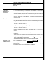
CAUTION
NOTE
The speed controller includes safety devices which, in the event of defects, may cause the speed controller to stop and thereby
stop the motor. This motor can itself sustain stoppage by a mechanical lock. Finally, voltage variations, in particular power cuts,
may also cause stoppages to occur.
The disappearance of causes of stoppage could cause restarting, dangerous to some machines or installations, in particular those
which must be in conformity with the decrees relative to safety.
Therefore, in such cases, the user must take stepsagainst such possibilities of restarting, more particulary by the use of a low
speed detector which, in the event of an unprogrammed stoppage of the motor, will cut off the speed controller supply.
The equipement design must be in conformity with the prescriptions of standard NFC 15-100.
More generally, any action, whether on the electrical part or the mechanical part of the installation or machine,must follow the cutoff
of the speed controller power supply.
SOFTWARE COMPATIBILITY
This type of RECTIVAR is equipped with V3● - version software.
It can replace V1● - or V2● - version RECTIVARs with the following conditions :
1-
RECTIVAR requiring the "vertical motion" cartridge :
use cartridge VW2-RLD221 which is the only one that is compatible with V3● -.
2-
For installations controlled or monitored via a serial link other RECTIVARs using
V1● - or V2● - : version software : use software which corresponds to the RECTIVARs
already installed.
References :
V1● - :
VW2-RZD101
V2● - :
VW2-RZD102
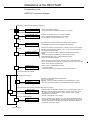
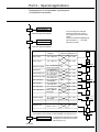
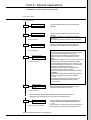
Contents
Part 1
Common applications
Page
Presentation - General
Characteristics- constitution
Control
Local dialogue
Motor selection - general block diagrams
1/4
1/5
1/6
1/7
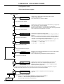
Description of the RECTIVAR
Selection guide
Functional characteristics
Connection terminals
1/8 to 1/11
1/12
1/13 to 1/16
Installation of the RECTIVAR
Mounting precautions
Dimensions and weights
Power connections
Power components layout - internal wiring
Layout of the components on the boards
1/17 -1/18
1/19 to 1/22
1/23 -1/24
1/25 to 1/32
1/33 to 1/37
Utilisations of the RECTIVAR
Presentation of the digital contol
Operating modes
Mode configuration
Assistance with maintenance :
fault processing
list of faults
memorisation of faults
display
Simplified sequence diagrams
Utilisation of the RUN, FORWARD and REVERSE signals
Utilisation of the speed references
1/38 to 1/40
1/41 -1/42
1/43 to 1/45
1/46
1/47
1/48
1/49
1/50 to 1/53
1/54
1/55
Initial setting up
Preliminary checks
Static checks
Dynamic adjustments
1/56
1/57 -1/58
1/59 to 1/64
Spare parts
1/66 to 1/68
Alphabetical index
2/38
For all special applications, see
summary in part 2, on page 2/1.
1/1
1/2
1/3
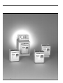
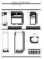
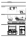
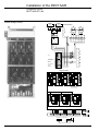
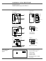
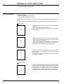
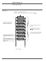
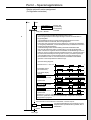
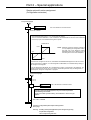
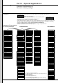
Presentation - General
RTV-74 non-reversing, 2 quadrants
RTV-84 solid state reversing 4 quadrants
The RECTIVAR RTV-74 32 to 3000 A single bridge three phase variable speed controllers are
designed for speed regulation of 6 to 1700 kW DC motors, with separate excitation.
The RECTIVAR RTV-84 16 to 3000 A double bridge three phase variable speed controllers are
designed for the speed regulation of 2,7 to 1300 kW DC motors with separate excitation.
Both series are supplied from an AC three phase mains.
Ratings : I (A)
Mains voltage (V)
Speed range
16, 32, 48, 72, 180, 270, 400, 650, 800, 1250, 1750, 3000
up to 660 ± 10 % - 50/60 Hz ± 5 Hz
1 to 300 - tachogenerator control
1 to 3000 with pulse generator and interface option
1 to 20 by U feedback, but the accuracy depends on the motor.
Characteristics
The RTV-74 speed controllers enable operation in quadrants 1 and 4 or 2 and 3 of the torque/
speed range.
The RTV-84 speed controllers enable operation in all 4 quadrants of the torque/speed range.
From the 800 A rating upwards, both series are fitted with a field current regulator.
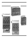
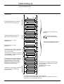
Constitution
The RECTIVAR 74/84 includes for each one of the series :
- 7 compact technology ratings from 32 to 650A, rating 16A is only available in RTV-84
- 4 modular technology ratings from 800 to 3000A.
• Compact technology combines in the same metal enclosure :
- the power part, with a 6 or 12 thyristor bridge and the thyristor protections, the control transformer,
a power interface board and its daughter board in the case of the 12 thyristor bridge, a galvanic
isolation board, the current transformers and the fans, if necessary
- the control rack, located at the front of the speed controller on the 8 ratings, includes the
microprocessor board, the display board and a dialogue keypad on the protective cover.
• The modular technology includes a power chassis and a control module connected by a set of
2 metre long, sleeved screened cables.
- The power chassis includes :
a 6 or 12 thyristor bridge with the thyristor protections, the firing circuits, the control transformer,
the thyristor protection fuses and the fan with its safety devices.
- The module known as the control module :
identical for all 4 ratings, includes :
- the thyristor excitation bridge
- the excitation current sensor
- the excitation control board
- the control transformers
- the power interface board
- the galvanic isolation board
- the control rack, identical to the one described above, located on the front.
For both technologies, the control rack, mounted on hinges, can pivot, enabling access to the part
at the back.
The control is completely isolated from the power part, the maximum voltage being 24 volts DC.
1/4
Presentation - General
Power interface boards
Control rack
Power interface
boards
• 16A rating
This carries : (see details page 1/33)
- the regulated power supplies
- the firing circuits and thyristor protections
- a double complete 12 thyristors bridge
- the control transformer's voltage adaptation link (CAV4)
- the two assignable function output relays : K1 and K2
- the current transformers
- the galvanic isolation board
• Ratings 32 to 650A.
This carries : (see details page 1/33)
-the regulated power supplies
- the firing circuits and thyristor protections
- the (RT) customization module for the speed controller rating
- the control transformer's voltage adaptation link (CAV4)
- the three power/control separation links (CAL) which enable a separate supply for the power and
the control, in position 1
- the two assignable function output relays : K1 and K2
- the galvanic isolation board
- the "6 firing gate" daughter board, for 12 thyristor power bridges.
• Ratings 800 to 3000A
This carries : (see details, page 1/34)
- the regulated power supplies
- the power bridge pulse transformer control circuits
- the customization connector (J4) for the speed controller rating
- the excitation bridge's firing circuit and thyristor protections
- the control transformer supply adaptation link
- the excitation transformer supply adaptation link
- the two excitation power/control separation links
- the two assignable function output relays : K1 and K2
- the galvanic isolation board.
Excitation control
board
(Ratings 800 to 3000A)
Digital control
rack
This carries the following functions : (see page 1/34)
- the field current regulator
- the pulse train firing circuit
- the switch on/off safety devices
- the excitation presence safety devices
- the flux reduction function
- other adjustment and safety circuits not used with digital control.
This includes two or three boards
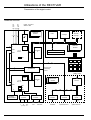
See hardware architecture, page 1/40.
• A microprocessor control board, carrying essentially :
- two 80C32 microprocessors and their associated EPROM programme memory banks
- the common external oscillator
- the communication transfer for communication between the two microprocessors
- the converters and safety devices necessary.
• A display and interface board to which are connected, by flat, disconnectable cable, the keypad
located on the front cover. It also includes :
- the RAM working memory
- the EEPROM backup memory cartridge
- the EPROM memory cartridge for optional additional programmes.
• An optional board with the pulse generator speed feedback functions, the frequency speed refer
ence and other optional utilisation interfaces (see part 2).
• The cover allows the display and the local dialogue keypad to be seen, with a concise serigra
phed label explaining their functions.
1/5
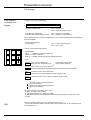
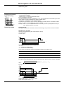
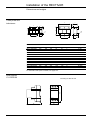
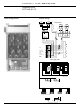
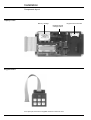
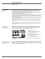
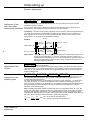
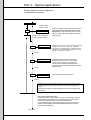
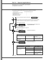
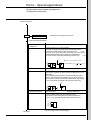
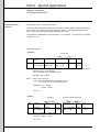
Presentation-General
The dialogue
Local dialogue
via display and
keypad
• 16 digit, 2 line, liquid crystal display
1
2
- In normal operating mode :
line 1 : speed in rpm
line 2 : armature current in amps.
- In configuration, adjustment,
calibration and keypad reference mode :
line 1 : question or parameters
line 2 : response or value (DATA).
Where adjustments are concerned, the flashing of one of the lines indicates that the parameter or
value is accessible.
- For automatic signalling
or fault analysis :
line 1 : number of faults present
line 2 : type of fault .
• Six key, three indicator light keypad.
green
yellow
CLEAR
PAR
red
- Indicator lights
red on
: controller on stop fault (page 1/46)
yellow on : current in limitation
green on : controller operating (RUN and operating direction).
- Keys
ENTER
DATA
ENTER : input of choice validation or
change to next configuration step
memorisation in both cases
of the position displayed
CLEAR : input of revert on incorrect choice or
fault acknowledgement when latching function of faults has been configured
PAR
: connection to the 1st line: Parameters.
This key is only used in Adjustment mode (see page 1/59)
DATA
: connection to the 2nd line : Value or response, or type of fault
Increase of value or response address
(up in menu tables).
Decrease of value or response address
(down in menu tables).
The two last functions are used in three ways :
- by pulse, for step by step scrolling
- by maintained actuation for continuous scrolling
- by maintained actuation with simultaneous maintained actuation of the CLEAR key for fast
scrolling.
LED
1/6
Case of controlled excitation for 800 to 3000A modular products :
- a green LED externally visible in the lower part of the control module, on to indicate when the
field regulator is on.
Presentation-General
Motor selection
The motor must be designed and of the right size for a pulse current supply with variable speed
and torque corresponding to the operation to be assured.
Form factor = 1,05.
It must have separate excitation or permanent magnets. Do not use a series or compound excited
motor.
In the case of controlled excitation, the maximum field voltage will be 0,8 times the mains voltage.
In the case of field weakening, the maximum field voltage will be 0,5 times the mains voltage
example : 190V for a 380V AC mains voltage. However, for machiner with long acceleration and
deceleration times (ramps > 5s), this ratio can be increased up to 0,8.
Recommended armature voltage ≤ mains voltage x 1,05 for RTV-84.
and ≤ mains voltage x 1,16 for RTV-74
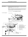
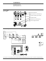
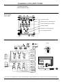
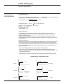
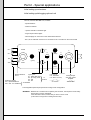
Functional diagrams
• Compact technology
R
I. exc.
U
P
1
TC
DT
M
2
+
A2
N
I
KE
IXI
A1
L.INV
SN
GI
µP
• Modular technology
GI
U
P
1
TC
M
DT
2
+
A2
N
I
KE
IXI
A1
L.INV
µP
IXI
P1
P2
P3
TC
tc
DT
L.INV
R
: 3 phase Graëtz bridge
: 3 phase Graëtz bridge (with RTV-84)
: 2 phase Graëtz bridge
: armature current measurement
: excitation current measurement
: motor speed measurement
: bridge control logic, depending on KE
: rectified field supply
GI
: pulse generator
(with interface option)
RTU
+
I
THRE
+
P3
tc
I. exc.
FID
1/7
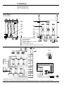
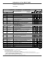
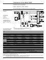
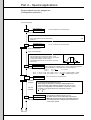
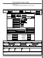
Description of the Rectivar
Selection guide
Motor /speed controller
combination
The speed controller reference which is stated on the delivery note and on the label located on
the left hand side of the device, must be referred to in all communications with our services.
Check the MAINS-CONTROLLER-MOTOR compatibility against the table below.
The values given correspond to an ambient temperature of 40°C. Above this, and up to 60°C,
apply a current derating factor of 1,2 % for each additional °C.
Three phase voltage Un ± 10 %
Mains : 50/60 Hz ± 5 Hz
RTV-74 controller
Max.
DC
Line
current
I rms
A
A
Motor
Maximum motor power with Starting torque/Rated torque = 1,2
220V
380V
415V
kW
kW
kW
480V
500V
660V
kW
kW
kW
kW
Excitation
current
Iex max.
A
440V
RECTIVAR
Reference
Weight
(1)
kg
32
24
6
10
10,5
12
11,5
13
-
15
RTV-74D32•
6,500
48
36
9
15
16
18
17
19,5
-
15
RTV-74D48•
10,000
72
54
13,5
23
24
27
26
30
-
15
RTV-74D72•
10,000
180
135
33,5
57,5
60
67,5
65
75
-
15
RTV-74C18•
11,000
270
203
51
86
90
101
97
112
-
15
RTV-74C27•
13,000
400
300
78
132
138
166
150
171
-
15
RTV-74C40•
47,000
650
488
127
214
224
253
243
278
-
15
RTV-74C65•
47,000
800
600
156
264
275
312
300
342
450
30 (2)
RTV-74C80•
54,000
1250
938
244
413
432
487
469
535
704
30 (2)
RTV-74M12•
54,000
1750
1313
342
578
604
683
657
749
985
30 (2)
RTV-74M17•
60,000
3000
2250
585
990
1035
1170
1125
1285
1690
30 (2)
RTV-74M30•
220,000
260V
220V
Q
440V
380V
Q
460V
415V
Q
520V
440V
Q
500V
480V
S
570V
500V
S
750V
660V
Y
Armature voltage
Mains voltage
Voltage code letter
(1) Basic reference to be completed by the voltage code letter. For C80• to M30• ratings, the
Rectivar includes two sub-assemblies (see page 1/10).
(2) Field regulation incorporated in control module. 3 ratings with 10A - 20A - 30A current
selection by link.
1/8
Description of the Rectivar
Selection guide
Three phase supply Un ± 10 %
Mains : 50/60 Hz ± 5 Hz
RTV-84 controller
Max.
DC
Line
current
I rms
A
A
Motor
Maximum motor power with Starting torque/Rated torque = 1,2
RECTIVAR
Reference
220V
380V
415V
440V
480V
500V
660V
kW
kW
kW
kW
kW
kW
kW
Excitation
current
Iex max.
A
Weight
-
-
2
RTV-84D16Q
6,000
(1)
kg
16
12
2,7
4,7
5
5,3
-
32
24
5,5
9,5
10
10,5
11,5
12
-
15
RTV-84D32•
6,500
48
36
8
14
15,5
16
17,5
18
-
15
RTV-84D48•
10,000
72
54
12
21
23
24
26
27
-
15
RTV-84D72•
10,000
180
135
30,5
54
59,5
63
67
70
-
15
RTV-84C18•
11,000
270
203
46
81
89
93
101
105
-
15
RTV-84C27•
13,000
400
300
69
120
132
138
150
156
-
15
RTV-84C40•
47,000
650
488
112
195
214
224
243
253
-
15
RTV-84C65•
47,000
800
600
138
240
264
275
300
312
408
30 (2)
RTV-84C80•
108,000
1250
938
215
375
413
432
469
487
637
30 (2)
RTV-84M12•
108,000
1750
1313
302
525
578
604
657
683
813
30 (2)
RTV-84M17•
120,000
3000
2250
518
900
990
1035
1125
1170
1530
30 (2)
RTV-84M30•
298,000
Armature voltage
230V
400V
440V
460V
500V
520V
680V
Mains
Voltage code letter
220V
Q
380V
Q
415V
Q
440V
Q
480V
S
500V
S
660V
Y
(1) Basic reference to be completed by the voltage code letter.
For C80• to M30• ratings, the Rectivar includes two sub-assemblies (see page 1/10)
(2) Field regulation incorporated in control module. 3 ratings with 10A - 20A - 30A current
selection by link.
1/9
Description of the Rectivar
Selection guide
Constitution of the
modular controllers
Supply voltages
The following types of Rectivar are modular : RTV-74 and RTV-84 from C80• to M30•
with separate power and control. Each of the 2 parts has its own reference:
Rectivar 74
Reference
RTV-74C80Q
RTV-74C80S
RTV-74C80Y
RTV-74M12Q
RTV-74M12S
RTV-74M12Y
RTV-74M17Q
RTV-74M17S
RTV-74M17Y
RTV-74M30Q
RTV-74M30S
RTV-74M30Y
Power part
Reference
VZ8-DH1C80Q
VZ8-DH1C80S
VZ8-DH1C80Y
VZ8-DH1M12Q
VZ8-DH1M12S
VZ8-DH1M12Y
VZ8-DH1M17Q
VZ8-DH1M17S
VZ8-DH1M17Y
VZ8-DH1M30Q
VZ8-DH1M30S
VZ8-DH1M30Y
Weight (kg)
54
54
54
54
54
54
60
60
60
220
220
220
+Control module
Reference
VW3-RZD1122
VW3-RZD1122
VW3-RZD1122
VW3-RZD1122
VW3-RZD1122
VW3-RZD1122
VW3-RZD1122
VW3-RZD1122
VW3-RZD1122
VW3-RZD1122
VW3-RZD1122
VW3-RZD1122
Weight (kg)
12
12
12
12
12
12
12
12
12
12
12
12
Rectivar 84
Reference
RTV-84C80Q
RTV-84C80S
RTV-84C80Y
RTV-84M12Q
RTV-84M12S
RTV-84M12Y
RTV-84M17Q
RTV-84M17S
RTV-84M17Y
RTV-84M30Q
RTV-84M30S
RTV-84M30Y
Power part
Reference
VZ8-DL1C80Q
VZ8-DL1C80S
VZ8-DL1C80Y
VZ8-DL1M12Q
VZ8-DL1M12S
VZ8-DL1M12Y
VZ8-DL1M17Q
VZ8-DL1M17S
VZ8-DL1M17Y
VZ8-DL1M30Q
VZ8-DL1M30S
VZ8-DL1M30Y
Weight (kg)
108
108
108
108
108
108
120
120
120
298
298
298
+Control module
Reference
VW3-RZD1122
VW3-RZD1122
VW3-RZD1122
VW3-RZD1122
VW3-RZD1122
VW3-RZD1122
VW3-RZD1122
VW3-RZD1122
VW3-RZD1122
VW3-RZD1122
VW3-RZD1122
VW3-RZD1122
Weight (kg)
12
12
12
12
12
12
12
12
12
12
12
12
• Power according to the tables
• Excitation: mains voltage 440V max. Excitation selection: 0,9 U mains with fixed excitation
0,8 U mains with field regulation
0,8 to 0,5 U mains with field weakening
For the S and Y references (480 or 500V or 660V mains) supply the excitation and its control
using a single phase transformer with a 380V or 440V secondary.
Transformer power : P = i exc x 1,10 U secondary (if fixed excitation, use i exc in cold state).
• Control : mains voltage 440V max
the control can be supplied separately from the power (CAL links). It must when using reference
S or Y. Use an auto-transformer, secondary 220/240V or 380/ 415V or 440V. Control circuit
consumption : 120VA for all ratings except ratings C18 and C27 with fan supply : 300 VA.
• Fans (see connections page 1/13)
- ratings D16 to D72 : no fan
- ratings C18 to C27 : fans supplied by the control : 220V/240V bypass the fan resistance on
the J11 connector on the power board (terminals 5 and 10)
- ratings C40 and C65 : One 220V-50/60Hz fan : 185W-0,85A
- ratings C80 to M17 : Two 220V-50/60Hz fans : 370W-1,7A in total, apart from one fan for the
RTV74
- rating M30
: Two 380V-50/60Hz fans : 1100W-2,4A in 50 Hz in total
1580W-2,9A in 60 Hz in total.
1/10
Description of the Rectivar
Selection guide
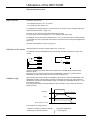
Selecting the speed
controller rating
Td/Tn
DC motor
2
1,75
Motor
compensated
1,5
1,25
Motor noncompensated
Id/In
1,25 1,5
1,75 2
Operating modes
The tables on pages 1/8 and 1/9 enable the speed controller rating to be determined for :
- continuous duty operation,
- starting torque 1,2 times the rated motor torque.
For cyclic operation, see below.
If the required starting torque is greater than 1,2 Tn, use the maximum current taken by the motor
Id (the starting current) to determine the speed controller rating :
- Id must be ≤ maximum DC of the speed controller.
To determine the maximum motor current Id depending on starting torque, consult the machine
curves or, if these are not available, the curves on the left.
Example : Td/tn = 1,6 non-compensated motor. Our curve gives Id/In (starting/rated current) = 2.
I max. speed controller ≥ 2 In motor.
Continuous duty
The speed controller has a maximum continuous DC rating (I max.) which cannot be exceeded.
Standard cyclic operation
Operation can be defined by two current values Io and Ip.
Ip = peak current,
Io = DC = Ip/2
I
Ip
Io
t
0
t1
t2
T
The following time limits must be complied with :
- t2 ≥ 7 t1,
- t1 ≤ 15s for 16 to 650A ratings,
- t1 ≤ 10s for 800 to 3000A ratings.
For Io and Ip, the maximum values for the different ratings are as follows (in A) :
I max cont. (A) 16
32
48
72
180
270
400
650
800
1250 1750 3000
Io
11
22
34
50
125
175
260
425
520
750
Ip
22
44
68
100
250
350
520
850
1040 1500 2100 3600
1050 1800
Particular cyclic operation
For a given known operating cycle, Imte, the equivalent mean thermal current must be calculated.
I21 t1 + I22 t2 + I23 t3 + ... I2n tn
Imte =
where T = t1 + t2 + t3 + ... + tn
T
Example :
I
I3
I4
I2
I5
0
t1
t2
t3
t4
t5
t
T
Imte =
2
2 2
2
3 3
I t + I t + I24 t4 + I25 t5
T
Current Imte must be ≤ 0,8 I maximum (DC).
Check that the peak current is ≤ Ip.
1/11
Description of the Rectivar
Characteristics
Three phase mains supply
voltage and frequency
Maximum, 440V ± 10% for D16, 500V ± 10 % for D32 to C65 660V ± 10% for C80 to M30 50/60 Hz ± 5 Hz
(45-55 / 55-65 Hz)
Recommended armature voltage
depending on the mains voltage
U armature ≤ U mains x 1,05 with the RTV84
U armature ≤ U mains x 1,16 with the RTV74
Excitation supply voltage
Maximum mains voltage 440 V - U excitation (see page 1/10).
Maximum excitation current
2A to 30A depending on the speed controller rating (see page 1/8 - 1/9 - 1/10).
Minimum excitation current
detectable by safety devices
D16 : 0,1A
Armature current limit
Adjustable on the controller from Ip/3 to Ip
(Ip = peak current of controller, see characteristics, page 1/11)
Speed range
1 to 300 with tachogenerator
1 to 3000 with incremental encoder option board
1 to 20 with voltage feedback but the accuracy depends on the motor
Static accuracy with variations :
- of resistive torque
0,2 Tn to Tn
with tachogenerator
with incremental encoder and digital reference
- 0,1 % of the maximum speed
- of mains voltage ± 10 %
- of ambient temperature
20°C ± 20°C
- 0,24 % of the set speed
- 0,066 % of the maximum speed
± 0,2 % of the set speed
± 1 % of the set speed
± 0,1 % of the maximum speed
Speed reference
• Two input voltages :
- by potentiometer
- by analogue signal
• One current input
• By serial link
The 3 inputs are summing and galvanically isolated from the power circuits.
0 to ± 10V, converted into 2000 points resolution + sign
1 to 10 kΩ connected to internal supplies : 0, + 10V ou 0, - 10V
0 to ± 10V, supplied externally. Input impedance 35 kΩ.
0 - 20 mA or 4 - 20 mA by configuration, impedance 100 Ω, resolution : 2000 points
Resolution 1 rpm
Configurable inputs – outputs
(see part 2 pages 2/10 to 2/15)
- 1 analogue input : 0 to ± 10V, impedance 35 kΩ, resolution 2000 points + sign,
- 2 analogue outputs : 0 to ± 10V, maximum load 5 mA, resolution 128 points + sign
- 4 logic inputs (+ RUN) : level 0 ≤ 1,5V/3,5V ≤ level 1 < 26,4V - impedance 2,2 kΩ
- 2 logic outputs : open collector, maximum load : 20 mA with 24 Vac (ex.: CA2 - EN 411)
- 2 relays with voltage free contacts : max 250 V a.c. On control relay : inrush 300 VA max,
sealed 30 VA max - 30 Vdc - 0,5A max, number of operations : 106
Minimum switching power : 24V/20mA a.c. or d.c.
Speed feedback
- by armature voltage : max 750
- by tachogenerator : max 320V
- by incremental encoder with VW1-RZD101 interface option : max 100kHZ
Reversing
(RTV 84)
By external signals on logic inputs or by inversing the reference signal.
Current reversal : dead band 15 ms.
Operation in all four torque/speed quadrants.
Acceleration and
deceleration ramps
(Page 1/54).
Acceleration and deceleration times separately adjustable from 0 s to 999,9 s.
"Overspill" function for automatic recopying of the speed feedback value, if the RECTIVAR is not validated.
Voltages and currents
available on the controller
(cumulative currents)
+ 15V or -15V maximum load 30 mA, for all inputs (control, validation,display, adjustment),
the option boards and all the external functions.
+ 24V maximum load 50 mA or 80 mA if no load on the + 15 V.
Degree of protection
IP00
Ambient temperature :
- for operation
- for storage
- 0°C to + 40°C (operation possible up to 60°C by derating the current by 1,2 % for each additional °C)
- 25°C to + 70°C
D32 to C65 : 0,5A
C80 to M30 : 1A
Derating according to
the altitude
Current derating by 0,7 % for each 100 m above 1000 m.
Qualification standards
See catalogue for RECTIVAR 4 three phase models.
1/12
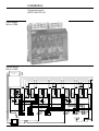
Description of the Rectivar
Connection terminals
Power bridge
Ratings 32 to 3000A
AL1
AL2
AL3
}
mains supply
earth (ground)
M1 +
M2 -
}
motor armature
The layout of the power terminals differs according to the rating (see pages 1/23 - 1/24).
In particular, the fans are supplied from the terminals given below.
Reminder : for ratings C18 and C27 the fans are supplied by the control part of the RECTIVAR.
• Ratings 400 and 650A (C40 and C65)
0 - 220
separate fan supply
220 V single phase voltage - 50/60 Hz
185W power - current : 0,85A.
• Ratings 800 to 1750A (C80 to M17)
0 - 220 (RTV74)
fan supply
0A - 220A
0B - 220B (RTV84)
separate supply for the two fans
voltage 220V single phase - 50/60Hz
unit power 185W - current : 0,85A
9-91
10-101
207-208
fuse breaking
thermo-contact
1 contact ... line peak limiter fault
}
contacts NC
• Rating 3000A (M30)
0 - 380
ventilation presence module supply
Separate module
power terminals
(Ratings 800 to 3000A)
U1, V1, W1
U2, V2, W2
separate supply for the 2 fans - 380V AC
unit power : 550W in 50Hz, 790W in 60Hz
unit current : 1,2A in 50Hz, 1,45A in 60Hz
i.e. for the 2 fans
power : 1100W in 50 Hz - 1580W in 60Hz
current : 2,4A in 50Hz - 2,9A in 60Hz
9 and 91
10 and 101
203-204
fuse breaking
ventilation present
cover in position
FL1
FL2
}
}
contacts NC
single phase supply to excitation bridge
earth (ground)
F1 +
F2 -
excitation bridge positive output
excitation bridge negative output
1/13
Description of the Rectivar
Terminal referencing
Power interface
boards
There are three types of board for the whole range, each fitted systematically with the galvanic
isolation board
- 16A rating
- 32 to 650A range
- 800 to 3000A range
• 16A rating
Marking
P.J1
Function
CL1
CL2
CL3
RNA
RNB
K1A*
K1B
K2A*
K2B
FL1
FL2
F1 +
F2 AL1
AL2
AL3
M1 +
M1 -
1
2
3
4
5
6
7
8
9
control supply (**) - used if the power and control supplies are
separate (U > 440V) - power : 120VA
tachogenerator input
K1 relay voltage free contact
with configurable function
K2 relay voltage free contact
with configurable function
excitation bridge single phase supply
positive excitation bridge output
negative excitation bridge output
power bridge supply, 50/60 Hz three phase mains
motor armature
• 800 to 3000A ratings
Marking
P.J1
CL1
CL2
CL3
RNA
RNB
FTA
FTB
PTE
NTE
K2A*
K2B
K1A*
K1B
FC1
FC2
1
3
5
7
8
9
10
11
12
13
14
15
16
18
20
Function
Control supply - power : 120VA.
Tachogenerator input
+ 24V
sensor presence fault
+ 24V supply (10mA max)
- 24V supply (10mA max)
K2 relay voltage free contact
with configurable function
K1 relay voltage free contact
with configurable function
excitation control supply if power/control supplies
disassociated - power : 70VA.
* Maximum contact characteristics : see page 1/12.
** Special precautions must be taken when using a separate control supply (see page 1/56).
1/14
Description of the Rectivar
Terminal referencing
Power interface
board
• 32 to 650A ratings
Marking
P.J1
Function
CL1
CL2
CL3
RU
RNA
RNB
M1 +
FL1
FL2
F1 +
F2 K1A*
K1B
K2A*
K2B
TTA**
TTB
1
2
3
4
5
6
7
8
9
10
11
12
13
14
15
16
17
control supply (***) - used if the power and control supplies are
separate (U > 440V) - power : 120VA for 32, 48, 72, 400,
650A and 300VA for 180 and 270A (with fan)
armature voltage output
PTE
NTE
NC
18
19
20
tachogenerator input
M1 motor terminal
excitation bridge single phase supply
positive excitation bridge output
negative excitation bridge output
K1 relay voltage free contact
with configurable function
K2 relay voltage free contact
with configurable function
(thermal trip contact), radiator temperature probe
normally open contact, voltage free
(not connected on ratings 32 to 72A)
+ 24V supply
- 24V supply
not connected
screw
terminals
* Maximum contact characteristics : see page 1/12.
** Maximum probe contact characteristics (from the 180A rating).
- Utilisation : a.c. inductive 250V, inrush 300VA max, sealed 30VA max,
d.c. inductive 30V/0,5A max.
*** Special precautions must be taken when using a separate control supply (see page 1/56).
1/15
Description of the Rectivar
Terminal referencing
Control board
C.J1
Marking
Function
1
2
E1
0E1
Speed reference input n°1 : 0 ± 10V
0V of input E1
3
4
E2
0E2
Speed reference input n°2 : 0 ± 10V
0V of input E2
5
6
EC
0EC
Current speed reference input (configuration 0-20mA or 4-20mA)
0V of input EC
7
AI
Configurable analogue input
8
9
P10
N10
+ 10V reference potentiometer supply
– 10V reference potentiometer supply
10
0AI
0V of input AI
11
12
13
P15
N15
0V
+ 15V supply
– 15V supply
0V
14
15
16
AO1
LO1
0V
Configurable analogue output n°1
Configurable logic output n°1
0V
17
RUN
Validation of the controller (gate circuits, loops, ramp)
18
19
AO2
LO2
Configurable analogue output n°2
Configurable logic output n°2
20
21
22
23
PL
LI1
PL
LI2
Logic inputs supply (+ 24V =)
Configurable logic input n°1
Logic inputs supply (+ 24V =)
Configurable logic input n°2
24
25
PL
PL
Logic inputs supply (+ 24V =)
Logic inputs supply (+ 24V =)
26
LI3
Configurable logic input n°3
27
LI4
Configurable logic input n°4
28
29
30
31
+ EM
- EM
+ RE
- RE
Point to point serial link - see part 2, pages 2/34 to 2/37
See input and output characteristics page 1/12.
The configurable input/output assignments are described on pages 2/10 to 2/15.
1/16
Installation of the RECTIVAR
Safety precautions
Reception of the
controller
When unpacking the controller, check that it has not been damaged during transport.
Make sure that the speed controller reference on the label fixed on the left hand side conforms to
the delivery note corresponding to the purchase order, and to the correspondance table
(page1/10) for ratings C80 • to M30•
It is recommended to transport the controller in a horizontal position, or by using the lifting rings
(ratings 400 to 3000A). However the controllers can be placed on the ground in an upright
position, except for ratings 800 to 1750A.
If the controller has been stored or switched off for several months, turn the fan rotor by hand,
where applicable.
Climatic
environment
For ambient temperature and humidity, altitude, vibrations and shocks, and degree of protection,
see characteristics in the three phase RECTIVAR catalogue.
Protect the speed controller against dust, particularly conductive dust, corrosive gases and
splashing liquids.
In the event of danger of condensation :
If the controller is switched off for periods longer than one hour, a heating system must be fitted
(0,2 to 0,5W per square decimeter of the enclosure) automatically active the moment the
controller is switched off. This device maintains the inside of the controller at a temperature
slightly higher than the external temperature, thus avoiding any risk of condensation and dripping
water. When switched on, the heating caused by the internal components is sufficient to produce
this same effect.
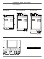
Mounting
precautions
Mounting in a
metal enclosure
Mount the speed controller in the vertical position so that the air circulates from the bottom to the
top of the cooling radiator fins.
Do not install near heat radiating elements.
If the controller must be installed in an enclosure, provide louvres for cooling air flow and, where a
cooling fan is fitted, provide an opening in the top of the enclosure with a protective cover and
filters if necessary.
Degree of protection IP23.
In order to ensure adequate air flow inside the controller :
- leave sufficient space around the unit :
• d ≥ 50 mm,
• D ≥ 100 mm.
- provide ventilation louvres,
- make sure that the ventilation is adequate, if not fit a cooling fan with filter.
D
d
θ° ≤ 40°C
θ° ≤ 40°C
d
D
- air flows :
• 180 and 270A bridges : 360m3/h
• 400 and 650A bridges : 1300m3/h
• 800 to 1750A bridges : 2600 m3/h for RTV-84
1300 m3/h for RTV-74
• 3000A bridges : 3600m3/h
1/17
Installation
Precautions
Mounting in a general
purpose metal
enclosure
Mounting in dust and
damp protected
metal enclosure
- power to be dissipated :
Type of bridge
A
16
32
48
72
180
270
Power
W
110
150
200
270
600
850
Type of bridge
A
400
650
800
1250
1750
3000
Power
W
1200
2000
2400
3710
5250
9000
Degree of protection IP54
Fit a heat exchange device to dissipate the heat generated inside the enclosure.
See power dissipated by speed controller table.
Wiring
; ;;
• Insulation
Apart from the special earth terminal marked
no other conductors connected to terminal
blocks should be connected to earth or the protective earth of the installation.
• Analogue and logic external circuits of CJ1 terminal must be wired using screened and twisted
pairs (pitch ≤ 5 cm) as well as RNA-RNB terminals of PJ1 terminal block.
Keep the control and power cables as separated as possible.
The screenings of cables connected to CJ1 should be wired directly to the 3 earth terminals
specifically provided for that purpose on the speed controller control rack. The tachogenerator
screening should be connected to the earth terminal provided for that purpose near the power
interface board. The maximum length of connections other than the speed reference and
feedback will be 5 m.
Above this, fit an interface circuit.
Filter module
Wrong
Right
wire soldered to the braid
braid wired directly to the terminal earth of
the speed controller
Delivered with the speed controller, connect it directly to the terminals ahead of the line inductances.
Its use is obligatory.
If power and control are supplied separately, connect the module directly to control terminals CL1,CL2
and CL3.
For 16 A and 800 à 3000 A ratings, connect it directly to control terminals CL1,CL2 and CL3.
Speed controller
cover
This serves as an electromagnetic screen for the control board, and as a support plate for the
dialogue keypad.
Avoid operating the controller when the cover is off or open.
1/18
Installation of the RECTIVAR
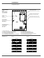
Dimensions and weights
Fixings : 4 x ∅ 6,5
Fixings : 4 x ∅ 6,5
RECTIVAR 270A
G
a
72
c
80 mini
H
b
Ventilateur
H
b
Ventilateur
10
10
RECTIVAR 16 to 180A
80 mini
c
G
a
Cooling spacers for 180A and 270A rated controllers mounted on flat surfaces.
Reference VY1-RZD102, to be ordered separately.
RECTIVAR
RTV-84D16Q
RTV-74/84D32
RTV-74/84D48
RTV-74/84D72
RTV-74/84C18
RTV-74/84C27
Dimensions
a
231
231
231
231
231
231
b
323
323
323
323
323
403
Fixings
H
290
290
290
290
290
370
c
176
220
260
260
260 + (80)*
260 + (80)*
∅
6,5
6,5
6,5
6,5
6,5
6,5
G
200
200
200
200
200
200
Weight
kg
6
6,5
10
10
11
13
Control module VW3-RZD1122
RTV - 74/84 C80• to M30
500
685
370
403
153
10
RECTIVAR 400 and 650A
RTV - 74/84 C40• and C65•
268
350
260
200
231
337
375
Weight : 47 kg
Weight : 12 kg
Fixings : 4 x ∅ 8,5
Fixings : 4 x ∅ 8,5
1/19
Installation of the RECTIVAR
Dimensions and weights
RECTIVAR 800 to 1750A, power bridge : RTV - 84-C80• to M17•
power bridge : RTV - 74-C80• to M17•
=
=
401
335
=
4 x Ø9
110
4 x Ø9
5
8
680
938
680
938
110
=
353
766
700
153
P7
RECTIVAR
RTV-84C80• to M12•
RTV-84M17•
P7
270
278
Weight (kg)
108
120
RECTIVAR
RTV-74C80• to M12•
RTV-74M17•
P7
270
278
Weight (kg)
54
60
RECTIVAR 3000A, power bridges : RTV - 74-M30•
RTV - 84-M30•
a
b
423
330
floor fixings
viewed from A
330
568
8 x Ø12
a
71
330
472
71
139
330
608
705
b
Weight (kg)
139
RTV - 74 1330 1400 220
RTV - 84 1670 1740 298
A
↑
1/20
Installation of the RECTIVAR
Dimensions and weights
Three phase line
inductance
c
a
c
b
b
a
ø
Ø
G
H
G
H
Reference
a
b
c
g
h
ø
Weight (kg)
VZ1-L015UM17T
VZ1-L030U800T
VZ1-L040U600T
VZ1-L070U350T
120
150
180
180
150
180
215
215
80
120
130
150
60
75
85
85
52
76
76
97
6
7
7
7
2,100
4,100
5,100
8,000
VZ1-L150U170T
VZ1-L250U100T
VZ1-L325U075T
VZ1-L530U045T
VZ1-L650U038T
VZ1-LM10U024T
VZ1-LM14U016T
VZ1-LM24U010T
270
270
270
380
390
400
420
420
240
240
240
410
410
410
490
550
170
220
240
225
275
310
340
385
105
105
105
310
310
310
310
310
96
125
138
95
100
125
125
155
11,5
11,5
11,5
9
9
9
9
9
14,900
24,300
28,900
37,000
46,000
66,000
80,000
120,000
For association with speed controller, see page 1/67.
Filter module
VY1 RZD106
90
Mounting on AM1-ED rail
73
45
1/21
Installation of the RECTIVAR
Dimensions and weights
Fuses
Association with
controller (see page 63)
L
ø
L
51
58
ø
14
22
Reference
DF3-NF25002
DF3-NF40002
DF3-NF50002
DF3-QF80002
A
51
51
51
75
B
51
51
51
75
Reference
L
DF3-FF10001 58
C
32
32
32
43
D
66
66
66
77
E
51
51
51
51
F
25,5
25,5
25,5
37,5
ø
22
ø
8
8
8
12
a
d
c
Ø
Reference
DF3-EF04001
DF3-FF05002
For DF3-NF25002 to DF3-QF80002 fuses, use :
- a micro-contact, reference VZ1-P001
f
e
(1) Carriers for fuse sizes 14-51, 22-58 :
DF5-EA and FA.
• Carriers for DF3-NF. to QF fuses
- for separate mounting of the fuses.
WARNING : respect the creepage distances
between fuses
E.g. NFC 20.040
Ø
d
c
Fuse carriers
b
21,2
a
31,2
a
b
e
b
54
Ø 5,2
Ø 6,5
f
110
125
Reference Size
A B C D E F
DF5-EA61 14-51 105 22 48 24 17 85
DF5-FA61 22-58 115 30 55 24 23 90
b
Fuse
DF3-NF25002
DF3-NF40002
DF3-NF50002
DF3-QF80002
a
157
157
157
181
b
90
90
90
102
c
51
51
51
75
ø
8
8
8
12
b
a
a
d
d
Power terminals
protective cover
Reference
DF5-NZ01
DF5-NZ01
DF5-NZ01
DF5-QZ01
c
LA9-F701
Reference
LA9-F701
LA9-F702
LA9-F703
1/22
c
a
26
27
35
b
43
48
58
c
26
34
45
d
72
90
112
LA9-F702/703
Controller
RTV-74/84 D32 to C18
RTV-74/84 C27 (a.c.) and VW3-RZD1122 module
RTV-74/84 C27 (d.c.) and C40 and C65
Installation of the RECTIVAR
Power connections
AL1
29,5
15
J1 AL1
AL3
AL2
Calibre
16 A
F8
AL2
48
RECTIVAR 270A
AL3
AL1
48
15
7,5
†
RECTIVAR 32 to 180A
29,5
15
Ø 6,5
AL2
55
20
AL3
55
20
20
Ø9
10
RECTIVAR 16A
J10 M2 M1
- +
R
J6
F12 F10 F11
8A
F6
F4
J3
F7
A
F5
J2
F1
J8
F9
440 V
F3
380 V
J5
K1
K2
F2
K2B
7,5
15
146
15
Ø 11
48
M2-
M1+
25
142
55
M2-
25
12,5
K2A
K1B
K1A
RNB
RNA
CL3
J4
CL2
220 V/240 V
CL1
FL1
FL2
F1+
F2-
415 V
M1+
RECTIVAR 400 to 650A
S1
AL2
AL3
M2-
RTV-74/84C65
40
M1+
15
40
AL1
RTV-74/84C40
30
30
35
S1
102
102
42
S1
Ø 11
52
1/23
Installation
Power connections
Control module
VW3-RZD1122
105
58
Ø7
15
7
15
FL2
F1
F2
7
FL1
15
15
48
Ø7
98
RECTIVAR
800 to 1750A
8XØ14
S
40
P5 P6
3XØ14
5
8
M1+
M2-
153
116
249
203,5
P1 P2 P3
P7
RECTIVAR
P1
P2
P3
RTV-74/84C80• to M12• 26
RTV-74/84M17•
40
94
80
26
40
P4
P4
P5
RTV 84 RTV 74
516
151
38,5
529
164
41,5
P6
P7
S
26
40
270
278
63
80
RECTIVAR 3000A
AL1
AL2
AL1
AL2
AL3
AL3
M1
M2 M1
229
60
1/24
=
=
172
100
250
50
50
M2
ép 10
75
45
Installation
Component layout
RECTIVAR RTV-74
Power bridge
32 to 180A
AL1
AL2
AL3
1
Current transformer
2
Thermocontact for 180A rating only
3
Thyristor module (3 per controller)
4
Excitation rectifier
5
Résistance for 180A rating only
6
Control supply transformer
(1)
V11
V13
V15
V14
V16
V12
(1)
M2
M1
Internal wiring
16
J8
TH3
J6
TC3-2
TC2-2
TC1-2
TH2
1
18
J9
J5
1
G1
G1
G2
G1
G2
TC2
TC3
1
2
1
1
TC3-1
TC2-1
TC1-1
4
TH1
TC1
2
1
2
G2
1
18
J4
1
(1)
18
1
10
F6 F5
J10
F3 F1
16
J3
F4
F2
AL
AL
+
J11
1
10
A
H
B
C
D
E
F
G
Détail
Cutting
up of
carte puissance
power board
1
RV2
RV1
RH
V1
V2
(1) for 220V, on C18 models only, short out the RH resistance using terminals 6 and 10 of the J11 connector on the power board.
1/25
Installation of the RECTIVAR
Component layout
RECTIVAR RTV-74
Power bridge
270 to 650A
AL1
AL2
AL3
5
2
3
V11
V14
3
V15
V13
V12
V16
4
V11
4
1
2
3
4
5
6
7
M1+
V15
V16
V12
2
6
M2-
V13
V14
5
7
1
6
Resistance for 270A rating only
AL1
AL2
Current transformer
Thermocontact
Thyristor module (3 per controller)
Excitation rectifier
Control supply transformer
Fan connection terminals, ratings 400 and 650A (0 - 220)
AL3
M2-
Internal wiring
TC3-2
TC2-2
TC1-2
J6
TC2
TC3
1
2
1
1
TC3-1
TC2-1
TC1-1
4
J3
1
J10
TC1
2
1
16
2
10
J11
J8
16
1
10
D
E
F
G
A
H
B
C
1
(1)
RV1
TH1
TH2
TH3
RH
RV2
V1
V2
1
J9
18
J5
1
F6 F5
G1
K1
G2
K2
G1
K1
G2
K2
G1
K1
G2
K2
F3 F1
1
F4
F2
18
J4
-
1
Cutting up of
power board
AL
AL
+
18
Ratings 400 and 650A : fans connected to terminals 0 - 220
270A rating : for 220V short out the RH resistance using terminals 6 and 10 of the J11 connector of the power board.
1/26
M1+
Installation of the RECTIVAR
Component layout
RECTIVAR RTV-74
Power bridge
800 to 1750A
Internal wiring
800 to 1750A
208
GV1
207
Network protection
board
Terre
L22
L23 101
10
9
AL1 AL2 AL3
91
0
220
F1
firing gate
board
V11
A
C
A
G
K
G
K
firing gate
board
V13
E
S
E
S
A
C
A
G
K
G
K
N
B
N
R
V14
E
S
E
S
A
C
A
G
K
G
K
N
B
N
R
R
TI2
S1
Bl
S2
AL2
R
Bl
S2
M2AL1
N
B
N
R
F2
F6
S1
E
S
E
S
V12
F4
M1+
firing gate
board
V15
V16
TI1
black
blue
brown
F5
F3
0A
220A
L21
connections to
control module
AL3
1/27
Installation of the RECTIVAR
Component layout
RECTIVAR RTV-74
Power bridge 3000A
Internal wiring
Ventilation
Détecteur
detector
ventilation
Ventilation
Détecteur
detector
ventilation
M
M
B
N
Câblage
Controlcontrôle
wiring
N
B
M20
M21
W1 V1 U1
W2 V2 U2
non raccordé
Terminal
Bornier
B
N
BL
24V T1
0V
T2
M
J/V
N
O
M
J/V
R
BL
B
A1 A2 13 14
R
R
F
M
U1
V1
W1
U2
V2
W2
- Fans
- Ventilateurs
F
O
N
B
F
BL
R
F
- Vent.
control
- Alim.
module
module
supply
contrôle
vent.
0V
380V
9
91
10
101
203
204
- Fuse
- Disjonction
fusibles
contacts
- Présence
- Vent.
presencevent.
- Casing
- Prés. carters
presence
F
R
R
F
Firing gate wiring
V14
GK GK
V16
R
GK GK
N
A1 C A
GK GK
A1 C A
V13
N
R
N
B
B
V11
V12
R
N
N
B
V15
A1 C A
N
V11, V13, and V15
thyristors are
located in front
TI2
TI1
Bl
R
S1
Bl
R
S1
S2
S2
connection to control module
M1+
1/28
M2-
J/V
Installation of the RECTIVAR
Component layout
RECTIVAR RTV-84
Power bridge
32 to 180A
AL1
AL2
AL3
V25
V23
V21
V12
V16
Current transformer
2
Thermocontact, for 180A rating only
3
Thyristor module (6 per controller)
4
Excitation rectifier
5
Resistance, for 180A rating only
6
Control supply transformer
V15
V13
V11
V14
V22
V26
V24
1
M2
M1
Internal wiring
TC3-2
TC2-2
TC1-2
J6
TC2
TC3
1
2
1
Cutting up of
power board
1
TC3-1
TC2-1
TC1-1
4
1
(1)
J3
TC1
2
1
F6 F5
2
F4
F2
F3 F1
10
TH2
K
J5
-
18
AL
G1
TH6
AL
K
+
G1
J8
1
G2
G1
G2
G1
G2
G1
TH4
K
TH2
G1
K~
1
J1
18
G2
TH4
TH6
TH6
16
K~
G2
TH2
J10
K~
TH4
TH1
J9
1
TH1
TH3
G2
K~
J4
16
G2
TH5
TH5
K~
G2
18
G1
G2
G1
G2
G1
16
1
TH3
K~
TH1
G2
K
G2
J11
1
10
A
H
B
C
D
E
F
G
1
J2
16
G1
1
RV1
(1)
RH
TH5
K
RV2
V1
V2
G1
K
TH4
G1
1
(1) for 220V, on C18 models only, short out the RH resistance using terminals 6 and 10 of the J11 connector on the power board.
1/29
Installation
Components layout
RECTIVAR RTV-84
Power bridge
270 to 650A
AL1
AL3
AL2
2
5
3
V24
V22
V26
4
4
V11
V15
V13
5
V21
V23
V25
V14
V16
V12
3
7
1
6
6
M2-
M1+
1
2
3
4
5
6
7
2
Resistance for 270A rating only
Current transformer
AL1
Thermocontact
Thyristor module (6 per controller)
Excitation rectifier
Control supply transformer
Fan connection terminals, ratings 400 and 650 A
Internal wiring
TC3-2
TC2-2
TC1-2
TC2
TC3
1
2
1
AL3 M2-
1
1
J3
Cutting up of
power board
TC1
2
1
M1+
TC3-1
TC2-1
TC1-1
4
J6
AL2
2
10
TH2
K1
F6 F5
J5
18
F3 F1
G1
TH6
K1
AL
G1
K2
K1
K2
K1
K2
K1
G2
G1
G2
G1
G2
G1
TH4
TH2
AL
+
K1
G1
K2
F4
F2
1
J1
18
G2
TH6
K2
G2
TH2
TH4
TH6
K2
TH4
TH1
TH1
TH3
G2
K2
1
J4
J10
16
16
G2
TH5
TH5
K2
G2
G1
G2
G1
G2
G1
G2
K1
K2
K1
K2
K1
K2
TH3
K2
TH1
G2
K1
1
J2
16
J11
1
10
G1
TH5
D
E
F
G
K1
1
G1
RV1
G1
(1)
RH
K1
TH3
A
H
B
C
1
Ratings 400 and 650A : fans connected to terminals 0-220
270A rating : for 220V, short out the RH resistance using terminals 6 and 10 of the J11 connector on the power board.
1/30
RV2
V1
V2
Installation
Component layout
RECTIVAR RTV-84
Power bridge
800 to 1750A
Internal wiring
800 to 1750A
Network protection
board
101
A
C
A
G
K
G
K
θ
V21
A
C
A
G
K
G
K
S N
EB
S N
E
R
A
C
A
G
K
G
K
N
S
B
E
N
S
R
E
V26
V14
S
E
S
E
F15
θ
V23
A
C
A
G
K
G
K
N
B
N
R
θ
V15
A
C
A
G
K
G
K
N
S
B
E
N
S
R
E
V22
R
N
B
N
R
S2
M1+
AL2
207
S
E
S
E
Bl
Bl
GV1
N
B
N
R
R
S2
208
A
C
A
G
K
G
K
S1
S1
AL1
S
E
S
E
θ
V25
V12
F16
V16
F14
V24
θ
V13
F12
θ
V11
F13
F11
9
91
10
M2-
AL3
1/31
Installation of the RECTIVAR
Component layout
RECTIVAR RTV-84
Power bridge 3000A
Ventilation
Détecteur
ventilation
detector
Ventilation
Détecteur
detector
ventilation
M
M
B
N
Câblage contrôle
Control wiring
N
B
M20
M21
W1 V1 U1
W2 V2 U2
non raccordé
Bornier
Terminal
B
N
BL
24V T1
0V
T2
M
J/V
N
O
M
J/V
R
BL
B
J/V
A1 A2 13 14
R
R
F
M
U1
V1
W1
U2
V2
W2
- Fans
- Ventilateurs
F
O
N
B
F
BL
R
F
- Vent.
control
- Alim.
module
contrôle
vent.
module
supply
0V
380V
9
91
10
101
203
204
- Disjonction
- Fuse
fusibles
contacts
- Présence
vent.
- Vent.
presence
- Casing
- Prés. carters
presence
F
R
R
F
Firing gate wiring
V24
GK GK
V26
R
GK GK
B
GK GK
R
N
N
V21
V22
R
V23
A1 C A
B
N
V25
A1 C A
B
A1 C A
N
N
N
V11-V13-V15-V21-V23
and V25 thyristors
are located in front
N
N
A C A1
V14
B
B
V11
N
R
KG KG
N
A C A1
V16
V13
N
R
A C A1
KG KG
V15
N
R
KG KG
Connections to control module
M1+
1/32
V12
B
M2-
Bl
R
Bl
R
S1
TI1
S2
S1
S2
TI2
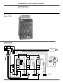
Installation
Components layout
16A power board
VX5-RLD101
J1 AL1
AL3
AL2
J10 M2 M1
- +
J6
Calibre
16 A 8 A
Choice of rating
8 or 16A according
to power motor
F12 F10 F11
F6
F4
F8
J3
Galvanic isolation
board
F7
F5
J2
F1
Adaptation of control
transformer supply
according to network
J8
Assignable K2 relay
F9
440 V
F3
380 V
Assignable K1 relay
J5
K1
Carte interface
puissance 32à 650A
VX5-RZD109
K2
F2
K2B
K2A
K1B
K1A
RNB
RNA
CL3
CL2
220 V/240 V
J4
CL1
FL1
FL2
F1+
F2-
415 V
J8
J7
J6
Adaptation of current reading
according to rating.
Current module, see page 1/66
RT
VH VL
VR
Choice of type of controller.
Set to VL for RTV-84
or VH for RTV-74
A
J5
Adaptation of the control supply
transformer to suit the mains
supply
J9
CAV4 0
Enables seperation of the control
supply from the power supply
in position 1
CAL
0
0
440
415
J12
380
For 220/240V mains on
ratings C18 and C27, add a
link on connector J11.
(see pages 1/25-1/26, 1/29-1/30)
240
220
1
1
J4
1
K2
J10
Assignable relay K2
B
J11
K1
J3
J13
J1
J3
J4-J5
J6
J8
J9
: Thermocontact
: Output to thyristor gate/cathode
: Current transformer reading link
: Power voltage take off
: RC connection to thyristor terminals
Assignable relay K1
J2
J10
J11
J12
A
B
: Supply and output of the control transformer
: Fan supply
: Speed feedback - Adaptation galvanic isolation board
: Reversible firing gate board (for RTV 84 only)
: Galvanic isolation board
1/33
Installation
Components layout
Power interface
board
800 to 3000A
VX5-RZD202
J25
J24
J23
J22
Choice of type of product.
Positionned at RT (RTV74 or RTV84).
J20
10
J11
1
A CA6 CA1
ST ST
RT RT
J7
J6
CA4
ST RT
J14
4
J15
1
J10
380/415
440/480
16
16
Control transformer
supply adaptation
depending on the
mains voltage
J3
220/240
0
Customization connector
for the current rating
to be fitted before
initial setting up
see p. 1/66
Enables disassociation of the control
supply and the excitation power supply
16
J12
1
CAV4
1
Excitation control transformer supply
depending on the mains voltage.
1
220/240
380/415
440/480
0
CAL
EXC
Excitation current
feedback
adaptation link
1 J8 10
CAV5
18
1 J9 10
FL1
1
FC1 J13
J4
10
1
FU
K2
1
K1
FL2
FC2
20
J1
A : galvanic isolation board
J3 : excitation control transformer supply and output
J5 : excitation current transformer reading connections
J8, J9 : excitation control board connections
J10 : control transformer supply and output
J11, J12 : speed feedback and galvanic isolation board adaptation
Customization
connector J4
J21
RTV-74
J13 : excitation power voltage output
J14 : excitations thyristors gate/cathode output
J20 to J23 : to power bridge impulse transformers
J24 : power bridge current transformer reading connections
J25 : armature voltage reading connection.
RTV-84
RTV-C65
RTV-C65
1
J4
1
RTV-C80
RTV-C80
1
J4
1
J4
1
J4
1
1/34
J4
J4
RTV-M30
RTV-M30
1
J4
RTV-M17
RTV-M17
1
J4
RTV-M12
RTV-M12
1
J4
1
J4
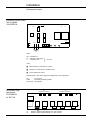
Installation
Components layout
Excitation control board
800 to 3000A
VX4-RZD104
1 J51
1
6
10
J8
1
J9
01
1
6
60 0
RTU I
J52
1
50 F/2 Rout
1
2
J53
6
Rin
Fid THRE G1 G2
ON
U>
0V
i<
3
LEDs :
ON : excitation on
U > : armature overvoltage
I < : excitation fault
non-active
Links :
1
Mains frequency selection 50 or 60 Hz
2
Operation at reduced flux, positionned at 0
3
To be switched to R.OUT.
Potentiometers : Non-active armature voltage loop via microprocessor
Fid
: any position
THRE
: in the fully clockwise position
G1 and G2 : any position.
J1
Reversible firing
gate board
VX2-DB303L
for RTV-84
J1
J2
J2
: Output to thyristor gate/cathode V22, V24 and V26
: Output to thyristor gate/cathode V21, V23 and V25
1/35
Installation of the RECTIVAR
Component layout
Galvanic isolation board VW2-RZD2071
Type of speed controller
Type of strips
RTV-84D16Q
Strip n°2
J1
J10
J61 J62
4
J1 J3
J12-16
J12-15
J12-14
J12-13
J12-12
J12-11
J22-1
J22-2
J22-3
J22-4
J21
(+15V)
(-15V)
(RTN)
(RTU)
(0V)
(0V)
J22
2
VW2J8
4 pin
connector
J4
J12-6
(RNA / R31)
J12-1
(RNB)
16 pin
connector
Strip n°3
32 to 650 A speed controllers
VW2-
Power board
2
J12
J3
J1
J22
(RU)
J3
10 pin
connector
3 pin
connector
J1
3
J13
To be connected to
screw terminal M1 +
on the power board
M1 +
Strip n°4
800 to 3000 A speed controllers
VW24
J11
J12
J1
J3
J1
M1+
RU
10 pin
connector
J3
10 pin
connector
J22
Carte puissance
Switch and offset
potentiometer
layout
2
1234
P1
Connector strip number
• Link to be positioned according to
maximum armature voltage
1 - from 0 to 260V
2 - from 261 to 460V
3 - from 461 to 570V
4 - from 571 to 750 V
Errors may cause faults to appear
on the display
1/36
Installation of the RECTIVAR
Components layout
Control rack
Display board
Control board
Control board
Field weakening
Power interface board
connection
Reversible firing gate
connection (RTV-84)
Display board
connection
Option connection
Customer connection
1/37
Installation
Components layout
Display board
Memory cartridge
Keypad board connection
EPROM optional
cartridge location
Keypad board
As a spare part, this board is supplied mounted on the front cover
1/38
Utilisations of the RECTIVAR
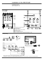
Presentation of the digital control
The RECTIVAR RTV74-84 controllers are fully digitalized for :
- the current and speed loops
- the processing of internal and external faults
- local and remote dialogue.
The task division between the two microprocessors is as follows :
• microprocessor n°1 controls :
- logic inputs and outputs
- the display/keypad and faults
- point to point serial link
- the calculation of speed references
- the acceleration and deceleration ramps
- speed regulation loop.
• microprocessor n°2 includes control of :
- the current regulation loop
- thyristors, via transfer modules
- the analogue inputs and outputs
- the mains safety processes.
For dialogue exchanges, microprocessor n°2 is considered to be the master.
These exchanges are inhibited during the configuration process. In this mode, only micro-processor n°1 is operating which stops, for example, the fault processing during this operation.
The algorhithms used for the calculations transcribe the following adjustment loop diagrams :
Kp - KI
Reference
+
+ k
+
Speed feedback
_
_
_
∫
I
I retour
feedback
I
I
where Kp and KI represent the proportional and integral factors and ∆ I the development of the
current between arch n and arch n-1.
The basic time between index n-1 and n is 3.3 ms at 50 Hz and 2.8 ms at 60 Hz.
1/39
Utilisations of the RECTIVAR
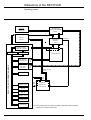
Presentation of the digital control
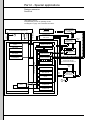
Hardware structure
LI1
K1
LI2
K2
LI3
L01
LI4 RUN L02
POINT TO POINT
SERIAL LINK
4
Optional
EEPROM
CONTROL
BOARD
RAM
EPROM
cartridge
4
cartridge
DISPLAY
IT
RAM
PORT
PORT
BOARD
µ P n°1
80C32
EPROM
µ1
Display
TM0
TRANSFERT
8
Thyristor and
reversibility
control
green
yellow
CLEAR
PAR
ENTER
DATA
red
MULTI-DROP
SERIAL LINK
RAM
EPROM
µ2
µ P n°2
80C 32
IT
OPTIONAL
INTERFACE
BOARD
RS 485
PORT
IT
MAINS
SAFETY
PROCESSES
TM0
TM1
TM2
A/D
converter
D/A
converter
F/D
converter
F/D
converter
Logic
inputs
13
Feedbacks E1 + E2
I
N
EC
(U.TG) AI
1/40
A01
A02
Excitation
reference
N (PG)
feedback
Frequency
speed reference
Digital
speed reference
Utilisations of the RECTIVAR
Operation modes
The digital control RECTIVAR RTV74-84 includes, when switched on, several operating modes,
shown in the diagram on the following page.
This diagram is considered to be in local dialogue mode (keypad and display), that is, when any
serial link interventions which may occur, are not accepted.
If the serial link is used, see part 2 : Special applications, pages 2/25 to 2/37.
Supply failure
Any power switch off, voluntary or involuntary, of the electronic control is supervised by a no-volt
safety device.
A momentary power failure lasting less than 3,3 ms at 50Hz (2,8 ms at 60Hz) has no effect, longer
supply losses are detected and the "Short power fail" alarm fault control locks the firing gates.
Above 10 ms at 50Hz (8,4 ms at 60Hz), the "Mains volt drop" fault appears and can necessitate
resetting (selectable).
In the event of power failure, the digital control board supply has a 50 ms back up, which enables
the assuring of any memorizations necessary (maximum memorization time limited to 20 ms). For
example, short power failures lasting from 3,3 ms to 10 ms (at 50 Hz), which, during
operation,
do not create any major problems despite the short interlock, are memorized in the fault processing (see "Short power failure" page 1/47).
Voltage recovery causes reversion to the stage reached in the diagram, after reinitialisation and
automatic memory test.
Note :
Bearing in mind the fault control, it is recommended to leave the control supply circuits independent from any opening of the line contactor which may occur. Special attention must always be paid
to the RUN signal control (see page1/54).
Procedure
• Access to the question "Operation mode ?" is carried out according to the following procedure :
- turn the key, located in the upper part of the speed controller, to the "Unlock" position, it is then
captive
- then press and simultaneously
• The operating mode menu then appears on the second line of the display. It can be scrolled by
using the keys or and choice of input is validated using ENTER which causes the corresponding parameters to appear. PAR and DATA do not have any effect. As a general rule, the
operating mode output is achieved by pressing ENTER (see detailed procedure for each mode).
• Quitting the operating mode procedure can be performed :
- definitively :
by returning the key to the "Lock" position, the key being taken out or not, whether at the
operation mode selection level, or already in an operation mode.
- temporarily :
by the appearance of stop faults in the RECTIVAR until these faults are acknowledged.
by a 15 second break in all keypad activity but only if the display is showing the question
"Operation mode ?". The mode quit can only either be voluntary, or due to a stop fault. Reversion to the question "Operation mode ?" can then be achieved by pressing any key on the
keypad.
1/41
Utilisations of the RECTIVAR
Operating modes
FACTORY SET
PRODUCT
FIRST SUPPLY
SWITCH-ON
CHANGEOVER
SUPPLY
OFF/ON
WORKING STATE (1)
NORMAL DISPLAY
SPEED AND CURRENT
REVERT TO
CONFIGURATION
CONFIRMATION
AUTO OR KEY
REVERT TO
FACTORY
SETTINGS
CONFIRMATION
SELECTION OF OPERATING MODE
KEY + CODE
1234567890123456789012
12
1234567890123456789012
12
12
12
12
12
12
12
12
12
12
12
12
12
12
12
12
12
12
Initial fault
12
12
AUTOMATIC
12
12
MEMORY
12
12
TESTS
12
12
12
12
12
12
12
12
12
12
12
12
12
12
12
CONFIGURATION
12
12
12
12
12
1234567890123456789012
12
1234567890123456789012
12
12
12
12
12
12
12
12
12345678901234567890123456789012123456789012345678901234567890
12
INITIALISATION
RECOPY PROGRAMME,
VALUES ...
Board or cartridge
change
ADJUSTMENTS
Fault
ack.
ALARM FAULTS
Stop
fault
AUTOMATIC
DISPLAY OF
STOP FAULTS
PAST
FAULTS
RESET PAST
FAULTS
THERMAL STATE
SPEED
CALIBRATION
CURRENT
CALIBRATION
1/42
(1) In the working state, the speed controller is unlocked if the RUN signal
is present. It can then be operated.
Utilisations of the RECTIVAR
Configuration mode
Procedure
This operation mode is accessible locally via the keypad and the display.
During this mode the motor cannot be supplied.
It appears :
a)automatically when the installation is switched on for the first time.
b)from software version V2.1, if installation of the 2 base PROM memories causes modification of
the internal data structure.
This is not systematic and depends on software evolution.
If this does arise, entry into configuration mode is preceded by an obligatory passage through
the factory settings procedure, validated by the only possible answer : ENTER
Factory settings
< ENTER >
c) by deliberate choice of an operating mode having gone through the operating mode selection
access procedure.
In this case, input in the mode Operation mode ?
is achieved by pressing ENTER
Configuration
Without quitting Operation mode, the display shows the confirming question.
Configuration
< CLEAR > < ENTER >
Pressing CLEAR causes reversion to the question "Operation mode ?".
Pressing ENTER causes Working state to be quit and configuration mode to be entered.
Content
This mode is conversational with the display and the keypad. It causes the essential data of the
application to be recorded in the EEPROM memory, whether it concerns :
- the mains, motor, feedback speed reading (sensor or tachogenerator) characteristics, with the
limits due to the speed controller.
- the operation of certain "simple function" options
- the reassigning of configurable input/output roles conforming to the diagram required for the
application.
- the special assignments for processing the faults.
The last three series of assignments can easily be ignored, which simplifies the procedure for
most of the usual applications.
If necessary, see contents of part 2, page 2/1.
Recording
The start of configuration mode is indicated by the display of dialogue language selection :
Dialogue ?
Francais
or
English
or
Deutsch
or
Espanõl or Italiano
or
Portugues
When configuring, only line 2 of the display can be modified, using the scroll-up/down keys or .
The listing of the parameters is sequential and is carried out by pressing ENTER which memorises the answer in the EEPROM memory.
Pressing CLEAR has no effect during configuration except for the final validation (see end of page
1/45) or for rapid scrolling, in association with keys or .
PAR and DATA have no effect.
1/43
Utilisations of the RECTIVAR
Configuration mode
GRAFCET scroll down diagram
The display is shown in standard factory configuration
Dialogue ?
English
Start
Choice of language of dialogue
or Français or Deutsch or Espanõl or Italiano or Portugues
Scroll up/down of answer and/or ENTER
RECTIVAR 74/84 - V3.1
72 amps
Automatic recognition of type 74 or 84 and of software
version of RECTIVAR and rating from 18 to 3000A.
It is completed by the software version (ex. : V3.L)
ENTER
Recognition of any options installed (see relevant user's manuals).
This recognition assumes that the softwares are compatible.
ENTER
F= 50/60 Hz, Voltage?
400 volts
Scroll of answer and/or ENTER
Automatic recognition of mains frequency. Voluntary choice of mains voltage
adaptation from the following values : 48-60-110-127-220-240-260-380-400415-440-460-480-500-600-660.
Caution : the "armature voltage" indication limits below depend on this
choice.
• The mains voltage configuration from 460V to 660V inclusive,
necessitates the use of S or Y voltage reference products.
There is no automatic recognition.
• In the same way, do not configure more than 440V on the RTV84D16Q
which is not recognised other than as a high rating controller with a 16A rating
module, which could be supplied at 500V.
N feedback type ?
Tachogenerator
Choice of type of speed feedback reading :
- or Armature voltage
- or pulse generator if the VW1-RZD101 option board is present
Scroll of answer and/or ENTER
If tachogenerator chosen
Tachogenerator
0,06V/tr/mn
Indication of the tachogenerator characteristics
from 0,01 to 0,20V/rpm
Warning : maximum voltage permissible on the RNA-RNB input : 320V
The product of maximum speed by TG characteristic must be at least 6V
Scroll of answer and/or ENTER
If pulse generator selected (only possible if option board is present).
Pulse generator
1000 pulses/rev
Scroll of answer and/or ENTER
Pulse generator characteristics indication from 100 to 9999 pulses/motor rev
Warning : maximum frequency permissible : 100 kHz at maximum speed.
The minimum permissible frequency at max. speed is 15 kHz, but with
proportional loss of accuracy.
See also : VW1-RZD101 user's manual.
If armature voltage selected
N feedback conn. ?
Direct
Scroll of answer and/or ENTER
(see next page)
1/44
Decision whether to leave as direct, or to reverse the direction of the taking
into account of the speed feedback, encoder or tachogenerator signal. This
enables correction of an inverted speed feedback signal without modifying
the terminal or connector wiring.
Utilisations of the RECTIVAR
Configuration mode
Grafcet scrolldown diagram
From previous page
Rated speed
100 rpm
Indication of the rated speed corresponding to the maximum
armature voltage at full flux.
From 100 to 7000 rpm, 100 rpm by default
Scroll of answer and/or ENTER.
Maximum speed
100 rpm
Indication of the maximum motor speed (in field weakening, if appropriate)
from 100 to 7000 rpm, 100 rpm by default.
The value corresponding to a 10V reference on, for exemple E1.
Maximum speed is equal to 4 times the "Rated speed" ensuring this remains
within the limits of the tachogenerator or encoder.
Scroll of answer and/or ENTER
Armature voltage
... volts
Scroll of answer and/or ENTER
Insulation board
position 4
Indication of the maximum armature voltage
From 0,5 to 1,05 of the mains voltage (1,05 mains voltage by default), for
RTV-84.
From 0,5 to 1,16 of the mains voltage (1,16 mains voltage by default), for
RTV-74. The value shown will act as an armature overvoltage threshold
calculation : 1,10 times the value of armature voltage.
The value can be changed during the adjustment procedure (page 1/61).
Indication of the jumper position on the galvanic isolation board.
1 : 24 to 260 V
2 : 261 to 460 V
3 : 461 to 570 V
4 : 571 to 750 V
Scroll of answer and/or ENTER
Armature voltage feedback configured
Not configured
Armature RI
... Volts
Predisplay of RI compensation adjustment from 0 to 33% of the armature
voltage above, 5% by default.
It can be changed during the adjustment procedure (page 1/61).
Scroll of answer and/or ENTER
Max. arm. current
... amps
Scroll of answer and/or ENTER
Indication of the maximum current permissible by the motor in the
application from 33% to 100% of the RECTIVAR peak current.
(Display by default = controller rating). It can be changed during the
adjustment procedure (page 1/60).
Change to special assignments, page 2/1 (second part of this manual), of the simple function options, the inputs/
outputs and the faults, pages 2/16 - 2/17 (part 2) then reversion to the following validation.
Config. accepted ?
< CLEAR > < ENTER>
Confirm, or revert to configuration mode at the beginning of
page 1/44.
CLEAR - Revert to start of configuration
ENTER - Change in working state. Use of ENTER is not active unless RUN = 0.
Working state
If "RUN = 1" when ENTER is pressed, the display shows this.
The RUN signal must then be switched off.
1/45
Utilisations of the RECTIVAR
Assistance with maintenance
Maintenance
The RECTIVAR series 74 and 84 do not require preventive maintenance.
It is, however, recommended to take the following measures at regular intervals :
- check the state and tightness of the connections,
- ensure that the fan is still effective, that the temperature around the controller remains at an acceptable level and that
there is no accidental condensation.
- remove any dust from the speed controller, if necessary.
In the event of any abnormality during operation, check, in addition to what is indicated on the screen, that the
recommendation relating to the environment and to mounting as regards connections, have been respected.
Fault processing
- The series 74 and 84 RECTIVAR controllers carry out monitoring and provide visual display (and transfer by serial
link) of a certain number of internally accessible faults, as well as two external faults (one stop fault, and one alarm, or
2nd priority fault). Three initial faults ("RAM", "EEPROM", "Module RT") are not memorised, but inhibit entry of
configuration data.
Nota :
- From software version V2.1, the installation of two uncompatible basic PROM cartridges causes the appearance of a
fourth initial fault, which inhibits the entry of configuration data.
This is displayed as
Prom 1 / Prom 2
- After switching off, the compatibility must be corrected according to the memory versions.
- A fifth initial fault may also occur during installation of an optional EPROM cartridge if not compatible with the basic
software.
This is displayed as
Prom 1 / Prom 2
Also refer to the corresponding EPROM manuals.
- A sixth initial fault “5 V option” appears if the 5 V supply wire bundle from the control transformer is not connected on the
VW1-RZD101 board, par ailleurs déjà raccordée à la carte contrôle.
This is displayed as
+ 5V option
This fault is tested only at initialisation. In working state the fault “Nfeedback absent ” is priority in cas of pulse
generator.
- The "EEPROM" fault is permanently retested, and all the other faults are classified in 4 families and 2 levels of priority.
• The 4 families are defined by combining in pairs the concepts stated below :
- Internal faults : concern the adjustment of the RECTIVAR, and its hardware
- External faults : concern the environment and the machine
- Static faults : can be detected with the machine switched off, without command on the RECTIVAR.
- Dynamic faults : appear when the machine is operating.
These families do not appear on the display; they provide an internal means of classifying the faults with differentiated
access for the latching function and, when necessary, an appearance hierarchy when commissioning.
• The two priorities are :
- stop faults : these cause the RECTIVAR to lock and the fault to be displayed automatically.
- alarm faults : these have no effect on the RECTIVAR, but they are memorised and can be retrieved for external
processing by a programmable controller, for example.
Some faults are assignable, as stop or alarm, by configuration.
If required, certain stop faults can be configured without the latching function (see next page).
In the event of displays of inexistant faults or in event of incoherent displays :
- switch off and check that the sceening connections is correctly realised on all circuits.Check also that the filter
module is mounted and the earth connections.
If after switch on the situation is abnormal again, this means that the EEPROM memory has been corrupted by
interferences:
proceded as below
- switch off
- maintened action with simultaneous maintened action on the CLEAR and ENTER key and switch on again without
release the keys,
- release the key.
You are sure to be in “ factory settings ” (see page 2/18).
Take care this procedure is exceptional.
1/46
Utilisations of the RECTIVAR
Assistance with maintenance
List of faults
ST : systematic stop,
TEXT ON THE DISPLAY
LINE 1
-
RAM
EEPROM
RT module
Number of
faults present
As above
Micropr. transfer
As above
As above
As above
EEPROM
A/D converter
24V voltage low
As above
Synchro signal
Number of
faults present
As above
Mains volt. drop
Third phase
As above
Freq over limits
As above
Short power fail
As above
As above
Serial link (1)
Excitation
Number of
faults present
As above
Overcurrent
As above
As above
As above
As above
As above
As above
As above
As above
As above
Display
I = 0 not reached
Thermal protect.
(1)
N = 0 not reached
(1)
Motor stalling (2)
Ramp unfollowed
(2)
Arm circuit open (1)(4)
Overspeed
N Fback reversed (1) (4)
N Fback absent (1) (4)
Ext. stop fault
Ext. alarm fault
Arm overvoltage (2)(5)
Y/N
CF : configurable stop/alarm
Priority
DETECTION CONDITIONS
LINE 2
PROM1/PROM2
Number of
faults present
As above
AL : systematic alarm,
Permanently
On initialisation
ST
AL CF
Latching
Y
N
O/N
(3)
** INITIAL FAULTS **
Incompatible basic memory
Memory test, incorrect reading
Memory test, incorrect write - read
Power rating module faulty or absent
** STATIC INTERNAL FAULTS **
Exceeding of answer time in test loop (> 1,8 ms)
The text is not used except for recorded "previous" faults
On initialisation, no exchanges for the first second or
time between exchanges > 20 µ s
Response time > 18 ms after writing
Conversion time > 50 µ s
24V voltage level internally filtered to 16V lower than 12V
Displayed if voltage level is sufficient to operate the display
Level of 24V established but synchronous clock signal
not appeared within 25 ms
** STATIC EXTERNAL FAULTS **
Level of 24V voltage, reduced to below 18V
for 10 ms at 50 Hz, 9 ms at 60 Hz
Third phase (not used for control supply) not present at initialisation
During operation monitored by excitation connected to third phase
The mains frequency adaptation has exceeded automatic operating
limits : 45/55 Hz or 55/65 Hz
24V voltage failure for more than 3 ms or 3,3 ms and less than
9 ms or 10 ms
Time longer than 1 second between reception of 2 requests
In fixed excitation, excitation current lower than excitation current ref.
In controlled excitation, fault in feedback from excitation control board
Fault not tested in half-flux or during current increase
**INTERNAL DYNAMIC FAULTS **
Current reading higher than 125% of the preset limitation value :
Incorrect adjustment of the armature current loop
Internal current reading data, not zero for more than
30 ms against "inversion limit"
**EXTERNAL DYNAMIC FAULTS **
100% threshold of the motor thermal exceeding : reached
Speed feedback not at zero although speed reference at zero for a
time adjustable from 1 to 360 seconds in configuration
Current in limitation at zero speed feedback for more than 10 seconds
Current in limitation at any speed for a time adjustable from
0 to 360 seconds in configuration
Zero current at zero speed with armature voltage not zero (immediate)
Speed feedback > 110% of maximum speed adjustment (immediate)
Tacho or encoder wiring reversed (immediate at low armature voltage)
Speed feedback zero with armature current and voltage not zero (imm.)
Assignable by configuration on a logic input LI1 to LI4
As above
U armature ≥ 1,10 configured indication
0
1
2
3
4
5
0
1
2
3
4
5
0
1
0
1
2
3
4
5
6
7
8
9
A
Number of bit in fault register (see page 2/28)
N.B : The special application optional memory cartridges provide additional fault processing.
See the relevant user's manual.
(1) No systematic latching in alarm, configurable in stop fault.
(2) No systematic latching in alarm, systematic latching on stop fault.
(3) The (Y/N) reconfiguration of the latching function is not possible except for all the faults concerned at the same time.
By default, latching is configured. Acknowledgement of latched faults must be carried out by the CLEAR function, active if RUN = 0
If RUN = 1 during CLEAR pressing, the display shows this.
(4) Faults not monitored in speed feedback by the armature voltage.
(5) With fixed excitation, this fault can appear in the cold state, with some motors.
1/47
Utilisations of the RECTIVAR
Assistance with maintenance
Fault memorization
Faults are recorded in :
- 3 zones of the RAM operating memory
- 1 zone of the EEPROM back up memory
The RAM zones are accessible by analysis in local mode, or by serial link (see part 2, pages 2/25 to
2/37).
The stop fault zone is automatically accessible on the display when a fault of this kind is shown.
RAM memory
Stop
faults
Actual
faults
Past
faults
• All faults appearing within 13,2 ms before a stop are recorded in
this zone.
They are memorised if they are latching.
If these faults appear, they cause an automatic visual display.
See next page.
• All faults are recorded in this zone, whether stop or alarm faults.
They are not memorised and are therefore visible during their
real development via serial link.
Because of the automatic priority display of stop faults (see
above), the voluntary analysis of this zone only gives access to
alarm faults, hence the name for this operating mode.
• All faults recorded in the "actual faults" zone are memorised in
the "past faults" zone which keeps a record of all faults which
have occured.
The second occurence of a fault only confirms the memorisation; there is no counting.
EEPROM memory
Past
faults
1/48
• A back-up of all development in the above zone is automatically
made in a corresponding zone in the EEPROM memory as a novolt safeguard. The instant a mains failure is detected, a
sequence of 20 ms enables a back-up to be made of the
development of the faults as they occur. A faults analysis
process enables the reset of the two previous faults zones.
Utilisations of the RECTIVAR
Assistance with maintenance
Automatic local
display
On the occurence, during operation, of one or more stop faults (systematic or configured), the
RECTIVAR locks just as if the RUN signal had disappeared. The red keypad indicator light goes
on and the display instantly shows :
nn stop faults
Overspeed
number of stop faults recorded and possible scrolling direction
name of first fault in order given on page 1/47.
The keys and
enable the scrolling of the names of the non-acknowledged faults present.
The scrolling limit is shown by arrows on the first line.
: first fault
: last fault
: intermediate fault
No arrow : one fault only
The other keys have no effect except CLEAR which acknowledges all stop faults present at this
moment if RUN = 0. If RUN = 1 during CLEAR, the display shows it on the first line
You must correct the RUN signal.
The acknowledgement of faults causes reversion to the "working state", with the speed and
current being displayed, provided that all the faults have actually cleared. If this is not the case,
the remaining faults are displayed again.
Voluntary local
display of faults
The access to operating modes process enables three replies to be accessed, relative to fault
analysis.
Input to the replies is achieved by pressing ENTER, just as is reversion to the question "Operation
mode ?".
Operation mode ?
Alarm faults
ENTER
03 Alarm fault
Serial link
ENTER
Operation mode ?
Past faults
ENTER
As a reminder, only the alarm
faults present in the actual
fault zone are concerned.
10 past faults
24V voltage low
ENTER
Operation mode ?
Past fault reset
ENTER
Past fault reset
< CLEAR > < ENTER >
ENTER or CLEAR
• In the first two analysis modes, the number of corresponding faults appears on the first line and
their names, in order given on page 1/47, can be scrolled using or within the limit of their
number, as shown above.
The keys PAR, DATA and CLEAR have no effect.
• Resetting past faults concerns both memory zones for that type of fault (RAM and EEPROM).
- Reset to zero, followed by returning to Operation mode ? is again achieved by pressing ENTER,
- Returning to Operation mode ?
Local display of
thermal exceeding
without action is obtained by pressing CLEAR.
The current thermal exceeding value is visible in this operation mode and can be accessed as
above by pressing the ENTER key (see page 2/17).
Operation mode ?
Thermal state
ENTER
Thermal state
.. %
Value also available
via serial link.
ENTER
1/49
Utilisations of the RECTIVAR
Simplified sequence diagrams
Supply : 380/415V or 440V, 50/60Hz
16 to 72A speed controller with factory configuration d'usine
Recommended circuit
diagram
L1
L2
L3
1
2
E1
S1
1
2
3
4
E2
S2
3
4
5
6
E3
S3
5
6
1
Q1
L1
F3
AL1
AL2
AL3
3
KM1
Q3
2
M1+
M
Q5
A2
4
æ
M2–
F1+
L1
CL1
F2–
T3
L2
CL2
æ
(1)
L3
1
A2
CL3
L1
2
13
L2
Q1
1
2
3
4
Q2
For more complex
sequences, see :
Q1
F2
FL1
FL2
E1
R
Q2
14
95
Assignable
inputs/outputs
(2)
T2
P10
14
13
L3
B
RNA
RNB
Q4
OE1
KA1
96
F3
PL
33
57
23
24
KA1
0,2s
RUN
34
58
S2
A1
(Part 2 of the manual)
13
S1
RTV-74
RTV-84
KA1
PL
14
A2
A2
KA1
LI3
PL
A1
A1
RTV-74
LI3
RTV-84
LI4
KM1
(1) Connections only possible for 16A rating.
(2) Connect transformer T2 or FL1-FL2 between phases 1 and 3. F2, T2, where required depending on AC supply and excitation voltages.
If power and control are supplied separately, connect VY1-RZD106 (A2) module directly to terminals CL1-CL2-CL3 (automatic for RTV-84D16Q).
Nomenclature of the required hardware
Reference
code
Description
Reference
Reference
Reference
Reference
Maximum power with Td/Tn = 1,2 and armature voltage 440V
M
A1
A2
F2
F3
Motor
Speed controller
Suppressor module (5)
Fuse + carrier
Fuse (3)
4,3 kW
10kW/9,1kW
15,5kW/14kW
RTV-84D16Q
RTV-74/84D32Q
RTV-74/84D48Q
VY1-RZD106
VY1-RZD106
VY1-RZD106
Rated at value of excitation current in cold state +DF6-AB10
DF3-EF04001 (2)
DF3-FF05002 (2)
DF3-FF05002 (2)
23kW/21kW
RTV-74/84D72Q
VY1-RZD106
KA1
Control relay
time delay block (3)
Line contactor
CA2-DN140MA65
LA3-D20A65
LC1-D163MA65
CA2-DN140MA65
LA3-D20A65
LC1-D253MA65
CA2-DN140MA65
LA3-D20A65
LC1-D403M
CA2-DN140MA65
LA3-D20A65
LC1-D503M
L11-L21-L31 Line inductances
VZ1 L015 UM17T
VZ1 L030 U800T
VZ1 L040 U600T
VZ1 L070 U350T
Q1
Q2
Q3
Q4
Isolator (1)
+ 3 fuses
Circuit breaker
Circuit breaker
Circuit breaker
GK1-EV
DK1-FB28
DK1-FB28
DK1-GB28
DF3-EF04001
DF3-FF05002
DF3-FF05002
DF3-FF10001
GV1-M..rated at 2 times the value of the primary T2 current in cold state + GV1-A01
GV1-M04
GV1-M04
GV1-M04
GV1-M04
GB2-CB06
GB2-CB06
GB2-CB06
GB2-CB06
R
Potentiometer
SZ1-RV1202
S1-S2
Control
XB2-M or XB2-B units, as required
T2
T3
Transformer
Transformer
Mains ≥ 440V, secondary 220V P (VA) = 1,5 P excitation (W) hot state motor.
Primary : 380V, 415V, 440V or 500V - secondary : 220V - Power 100VA
KM1
SZ1-RV1202
SZ1-RV1202
DF3-FF10001 (2)
SZ1-RV1202
(1) Quick blow fuses incorporated in the isolator.
(2) Fuses mounted on Ferraz carrier, (see page 1/22). For RTV-84D32S products, fit 2 fuses in the armature loop.
(3) For RTV84 only, unnecessary with RTV74.
(4) Connect directly to terminals CL1-CL2-CL3 for RTV-84D16Q
(5) The filter module is supplied with the speed controller
Note : if mains supply is other than 380/415V or 440V a.c., supply the control (CL1/2/3) via an auto-transformer, power ≥ 40 VA, secondary voltage 3
x 380V 50/60Hz.
1/50
Utilisations of the RECTIVAR
Simplified sequence diagrams
Supply : 380/415V or 440V, 50/60Hz
180 to 650A speed controller with factory configuration
Recommended circuit
diagram
L1
L2
L3
1
2 F11
E1
S1
1
2
3
4 F12
E2
S2
3
4
5
6 F13
E3
S3
5
6
Q1
L1
1
F3
AL1
AL2
AL3
CL2
Q3
For more complex
sequences, see :
2
T2
4
1
2
3
4
Q5
L3
Q1
6
5
F2–
æ
B
RNA
RNB
0 (2) P10
Vent E1
Q4
220
Q4
14
13
F11 à F13
F3
14
Q2
13
14
R
OE1
PL
23
TTA
RUN
Q4
24
KA1
TTB
33
57
0,2s
KA1
S2
A1
34
13
S1
KA1
PL
14
RTV-84
A1
RTV-74
A2
KM1
Description
FL2
4
3
2
58
Reference
code
FL1
T4
13
Nomenclature of the
required hardware
F1+
F2
2
1
1
L2
If power and control are
separately supplied, connect
VY1-RZD106 (A2) module
directly to terminals CL1-CL2CL3.
M
Q2
L1
(Part 2 of the manual)
CL3
(1)
T3
A2
Assignable
inputs/outputs
æ
M2–
CL1
KM1
3
M1+
A1
LI3
PL
A2
LI4
LI3
KA1
RTV-84
RTV-74
Note
* connect the T2 or FL1-FL2 transformer between phases 1 and 3
F2, T2 where appropriate, depending on the mains and excitation voltages
** Fan supplied separately for ratings > 270A.
Reference
Reference
Reference
Maximum power with Td/Tn = 1,2 and armature voltage 440V / 400 V
M
A1
A2
F2
Motor
Speed controller
Filter module (3)
Fuse
+ carrier
Fuse (2)
57kW
86kW
RTV-74/84C18Q
RTV-74/84C27Q
VY1-RZD106
VY1-RZD106
Rated at value of excitation current on cold
DF6-AB10
DF6-AB10
DF3-NF25002
DF3-NF40002
132kW / 120kW
RTV-74/84C40Q
VY1-RZD106
214kW / 195kW
RTV-74/84C65Q
VY1-RZD106
DF6-AB10
DF3-NF50002
DF6-AB10
DF3-QF80002
Control relay
+ time delay block (2)
Line contactor
+ coil
CA2-DN140MA65
LA3-D20A65
LC1-FF43
LX1-FF220
CA2-DN140MA65
LA3-D20A65
LC1-FG43
LX1-FG220
CA2-DN140MA65
LA3-D20A65
LC1-FJ43
LX1-FJ220
CA2-DN140MA65
LA3-D20A65
LC1-FK43
LX1-FK220
L11-21-31 Line inductances
F11-12-13 + fuses (1)
VZ1 L150 U170T
DF3-NF25002
VZ1 L250 U100T
DF3-NF40002
VZ1 L325 U075T
DF3-NF50002
VZ1 L530 U045T
DF3-QF80002
Q1
Q2
Q3
Q4
Q5
Isolator
Circuit breaker
Circuit breaker
Circuit breaker
Circuit breaker
DK1-HC2312
DK1-HC2312
DK1-KC2312
GV1-M.. rated at twice the value of the primary T2 current on cold + GV1-A01
GV1-M06
GV1-M07
GV1-M08
GV1-M06 + GV1-A01
GB2-CB06
GB2-CB10
GB2-CB10
DK1-KC2312
R
S1-S2
Potentiometer
Contol
SZ1-RV1202
SZ1-RV1202
XB2-M or XB2-B units, as required
SZ1-RV1202
T2
T3
T4
Transformer
Transformer
Transformer
≥ 440V mains, secondary 220V P (VA) = 1,5 P excitation (W) hot state motor.
250VA
400VA
630VA
630VA
Secondary 220V P = 250VA
F3 (1)
KA1
KM1
SZ1-RV1202
GV1-M08
GV1-M06 + GV1-A01
GB2-CB10
(1) Quick blow fuses to be mounted on DF5 carriers (see page 1/21) or on busbars.
(2) For RTV84 only, unnecessary for the RTV74.
(3) The filter module is supplied with the speed controller.
Nota : if mains supply is other than 380/415V or 440V a.c., fit a three phase auto-transformer, 380V 50/60Hz secondary, power ≥ 40VA for ratings
400 and 650A and 250VA for ratings 180 and 270A, to supply the control (CL1-CL2-CL3).
** RTV-84C40. and C65. : fan supplied separately at 220V single phase, 250VA power.
1/51
Utilisations of the RECTIVAR
Simplified sequence diagrams
Supply : 380/415V or 440V - 50/60Hz
800 to 1750A speed controller with factory configuration
Recommended
circuit diagram
L1
L2
L3
1
Q1
1(Q2)
3(Q2)
1
2
KM1
2
E1
L1
A1
S1
3
4
3
4
E2
S2
5
6
5
6
E3
S3
1
3
2
4
1
AL1 M1+
AL2
AL3 M2-
Q2
3
æ
A1
2
4
M
Q3
FL1 F1+
FL2 F2-
L1
RNA
L2
RNB
L3
P10
B
E1
A2
T3
æ
R
OE1
Q7
1
Q5
Q1
1
2
13
Q4
3
2
Q4
T4
5
6
0
Vent
4
220A (2)
14
1
2
3
4
5
6
PL
CL1
RUN
CL2
24
23
KA1
CL3
n
0 Vent
220B
13 14
33
57
0,2s 58
Q1 (1)
KA1
34
Q2
13 14
Q4
13
14
9
Q7
13
KA1
207
14
RTV-74
A1
A1
A2
KM1
A2
KA1
PL
LI3
91
101
10
S2
S1
RTV-84
RTV-74
PL
RTV-84
208
LI3
LI4
For more complex sequences, see assignable inputs/outputs, in part 2 of this manual.
Connections : respect the phase order given on the diagram.
(1) Circuit breaker contact, if necessary, depending on type of protection.
(2) Single cooling fan for RTV-74 speed controllers
Nomenclature of the
required hardware
Reference
code
A2
F4
KA1
Description
Reference
Filter module (3)
Fuse
Control relay
Time delay block (2)
VY1-RZD106
DF2-CA02 + carrier DF6-AB10
CA2-DN140MA65
LA3-D20A65
KM1
Line contactor
To be rated according to motor power - see paragraph (1)
L11-L21-L31
Line inductances
VZ1-L650 U038T (RTV..C80•)
VZ1-LM10 U024T (RTV..M12•)
VZ1-LM14 U016T (RTV..M17•)
Q4
Circuit breaker
GV1-M07 + GV1 - A01
Q6
Circuit breaker
GV1-M08 + GV1 - A01
Q7
Circuit breaker
GV1-M05 + GV1 - A01
S
Control
XB2-M or XB2-B as required
T4
Transformer
Secondary 220V P = 450VA
The Q1 - Q2 - Q3 - Q5 - T3 components will be selected according to the operating sequence of the speed controller and the
power of the motor with which they are associated.
Note : If the mains is other than 220V - 380/415V or 440V a.c. fit :
- a three phase auto-transformer, power ≥ 40 VA secondary 380V 50/60Hz to supply the control (CL1-CL2-CL3),
- a single phase transformer power (VA) = I excitation (hot state motor) x U transformer secondary, secondary 380V
50Hz, to supply the excitation (FL1-FL2).
(1) The line contactor normally operates at zero current and only opens when the machine is switched off. These stipulations
usually result in a thermal rating. The AC1 operating category according to standard IEC 158-1 for the rms line current,
calculated according to the type of continuous or cyclical duty. Take into account the ambient air temperature and the
possibility of wiring according to the choice of connections (cables or bars), and the capacity of the device's terminations.
(2) For RTV84 only, unnecessary with RTV74.
(3) Always connect the filter module (VY1-RZD106) to terminals CL1-CL2-CL3.
The filter module is supplied with the speed controller.
1/52
Utilisations of the RECTIVAR
Simplified sequence diagrams
Supply : 380/415V or 440V - 50/60 Hz
3000A speed controller with factory configuration
Recommended
circuit diagram
Q1
1(Q2)
3(Q2)
1
2
KM1
E1
2
L1
A1
S1
L1
1
L2
3
4
3
4
E2
S2
L3
5
6
5
6
E3
S3
1
3
2
4
1
AL1 M1+
AL2
AL3 M2-
2
æ
M
Q4
Q3
U1
V1 Vent
W1
T3
1
Q5
2
13
Q1
14
13 14
Q2
13 14
13 14
Q4
4
FL1 F1+
FL2 F2-
L1
RNA
L2
RNB
L3
P10
34
E1
A2
R
OE1
U2
V2 Vent
W2
1
Q7 2
3
4
0
380V
5
6
PL
CL1
RUN
CL2
24
23
KA1
CL3
204
9
RTV-74
PL
LI3
S2
10
S1
A1
B
91
KA1
RTV-84
æ
203
Q7
33
58
A3
2
n
Q1 (1)
0,2s 57
Q2
RTV-74
A2
KM1
13
A1
14
101
PL
RTV-84
LI3
LI4
KA1
A2
KA1
For more complex sequences, see assignable inputs/outputs, in part 2 of this manual
Connections : respect the phase order given on the diagram.
(1) Circuit breaker contact, if necessary, depending on type of protection.
Nomenclature of the
required hardware
Reference
code
A2
Description
Reference
Filter module (3)
VY1-RZD106
KA1
Control relay
Time delay block (2)
CA2-DN140MA65
LA3-D20A65
KM1
Line contactor
To be rated according to the motor power - See paragraph (1)
L11-L21-L31
Line inductances
VZ1 LM 24U010T
Q4
Circuit breaker
GV1-M08 + GV1 - A01
Q7
Circuit breaker
GV1 - M05 + GV1 - A01
S
Control
XB2-M or XB2-B as required
The Q1 - Q2 - Q3 - Q5 - T3 components will be selected according to the operating sequence of the speed controller and the
power of the motor with which they are associated.
Note : If the mains is other than 220V - 380/415V or 440V a.c. fit :
- a three phase auto-transformer, power ≥ 40 VA secondary 380V 50/60Hz to supply the control (CL1-CL2-CL3),
- a single phase transformer, power (VA) = I excitation (hot state motor) x U transformer secondary, secondary 380V
50Hz, to supply the excitation (FL1-FL2).
Fan supply : fit a three phase transformer P ≥ 1100VA if the mains is other than 380V.
(1) The line contactor normally operates at zero current and only opens when the machine is switched off. These stipulations
usually result in a thermal rating. The AC1 operating category according to standard IEC 158-1 for the rms line current,
calculated according to the type of continuous or cyclical duty. Take into account the ambient air temperature and the
possibility of wiring according to the choice of connections (cables or bars), and the capacity of the device's terminations.
(2) For RTV84 only, unnecessary with RTV74.
(3) Always connect the filter module (VY1-RZD106) to terminals CL1-CL2-CL3.
The filter module is supplied with the speed controller.
1/53
Utilisations of the RECTIVAR
RUN, FORWARD, REVERSE signals
Utilisation of the
RUN terminal
Connection of the RUN terminal to PL (+ 24V) assures the RECTIVAR unlocking by validating all
the control logic and the thyristor firing gates.
Absence of the RUN signal locks the RECTIVAR, slowing down is thus carried out in freewheel,
without dynamic braking torque.
The RUN command can be carried out by serial link. See part 2 of the manual page 2/26.
Precautions to take
to avoid unwanted
firings
• 1st case : control and power linked, links CAL at 0.
The RUN command can precede or follow switching on but MUST be cancelled before switching
off (≥ 0,2s).
• 2nd case : control and power separated, links CAL at 1 (or ratings ≥ 800A).
The control must be supplied upstream of the line contactor.
Respect the timing diagram below :
Line contactor (KM1)
RUN signal
t2 ≥ 0,2s
t1≥ 0
The RUN command must not precede the power supply, but its cancellation must be carried out at
least 0,2 seconds before switching off the power.
"Overspill" function
Utilisation of the
FORWARD, REVERSE
commands
When not carrying out a command (RUN and FORWARD or REVERSE or internal operation
command), or during the occurrence of a stop fault, the speed controller carries out an "Overspill"
function, that is, the speed feedback signal is copied in the speed ramp the moment the operation
command reappears. This function enables restarting while running under optimum conditions.
By convention, the FORWARD operation direction corresponds to positive signals.
FORWARD and REVERSE are factory assigned to logic inputs LI3 and LI4.
See special assignments part 2 of the manual, pages 2/9 and 2/14.
Example of connection to input 0/+10V on logic input E1.
FW
P10
LI3 (standard)
S1
2,2 kΩ
E1
PL
S2
0E1
RV
LI4 (standard)
For the RTV 74, FORWARD control is sufficient.
However, the REVERSE can be used with a negative reference connected to the N10 terminal.
1/54
Utilisations of the RECTIVAR
Speed reference inputs
Input functions
The speed controller has :
- two voltage inputs with ± 10V : E1 and E2,
- one current input with 0/20mA : Ec.
It is possible to reconfigure input Ec to 4/20 mA and to use a third on the AI analogue input (see
special assignements part 2, page 2/11).
The three (or four) reference inputs are algebraically summing.
For the Ec input, 20 mA corresponds to a + 10 V voltage on the other inputs.
The algebraic sum of the inputs is peak limited at ± 10V, or maximum limited or minimum limited,
or overridden at a lower configurable value with the low speed function (see special assignments,
page 2/15).
The input characteristics are given on page 1/12.
Utilisation of the inputs
Operating direction control by voltage polarity at E1, for RTV 84.
For example, with the FORWARD direction permanently activated (reversal by S1 when S2 is
closed).
FW
P10
S1
LI3
P10
S2
PR1
PL
E1
0E1
0E1
The same operation is possible with several simultaneous and algebraically additive speed
reference inputs.
With the RTV 74, a negative reference with the FORWARD command or a positive with the
REVERSE command are not taken into account and correspond to 0.
Validation logic
After unlocking, the speed contoller is validated by the presence of either the FORWARD or the
REVERSE command. This operation command is memorised once the logic commands have
disappeared, and until the speed feedback signal is cancelled (non-adjustable threshold < 2 % of
the maximum speed).
This arrangement enables electrical braking and the cancellation of the command if the RUN
signal is present.
FORWARD
Speed
Internal operation command
Two variations on the logic above :
- operation command by reference detector
- brake logic for vertical movement
See special applications
2nd part, page 2/1.
1/55
Initial setting-up
Preliminary checks
The digital control RECTIVAR series 74 or 84 is used, given the external connections, like a series 541 or 641
analogique control speed controller.
It adapts more flexibly to special applications (part 2) and enables clearer dialogue with the operator and the
surrounding system, but this does not detract from its being simple to use.
The RECTIVAR is factory configured and adjusted for the most common operating conditions. Nevertheless,
with the help of this manual, it must be checked that this configuration is suitable for the utilisation defined by
the design office, and if this is not the case, the product must be reconfigured.
Verification of the
kinematic chains
DC drive applications usually call for extremely precise speed regulation. This cannot be obtained without high
quality mechanical drives, which must be checked before connecting to the speed controller : fixing, coupling,
alignment, friction of reduction gears, motors and tachogenerators or incremental encoders.
With the supply
disconnected
Check the rating plates and the labels on the equipment to ensure that the speed controller, the motor and the
mains supply are compatible.
Make sure that the wiring corresponds to the circuit diagram.
Check that all terminals are tight and that the speed controller connectors are fully plugged in and latched.
Where a voltage speed reference is being used, check the connections of the speed reference potentiometer
and measure its resistance using a multimeter :
- suggested value : 2200 Ω (terminals 0E1 and P10 or N10 disconnected),
- recommended value : 1 kΩ ≤ R ≤ 10 kΩ,
- power : P ≥ 3W.
The cover of the RECTIVAR serves as an electromagnetic screen for the control board and as a support for
the dialogue keypad. Avoid operation when the cover is off or open. Control rack opening does not present any
danger as the maximum voltage is 24V for electronic boards.
However, retraction of the control rack does give access to dangerous voltage levels, notably the mains and
armature. Do not retract when ON.
Checking the power
links
Access to the power control board can be gained by retracting the control rack.
Ratings 16 to 650A
Check that the control voltage is compatible with the supply voltage (link CAV4). If the supply voltage is other
than 220/240V, 380/415V or 440V, set the CAL links in position 1 and fit an auto-transformer between the
mains and CL1-CL2-CL3 terminals to supply the control (secondary voltage compatible with a CAV4 position).
For rating 16A, no CAL link, alimentation systématique en CL1-CL2-CL3, check that the switch 8A/16A is in
position corresponding to the motor.
Check that the VH-VL/VR link is in position VH-VL, (upper position 32A to 650A).
Ratings 800 to 3000A
Check that the control and excitation voltages are compatible with the supply voltage (links CAV4 and CAV5).
If the supply voltage is other than 220/240V, 380/415Vor 440V fit :
- an auto-transformer between the mains and CL1, CL2, CL3 terminals to supply the control (secondary
voltage compatible with one of the CAV4 link positions)
- a transformer between the mains and the FC1-FC2 terminals to supply the excitation control ((secondary
voltage compatible with one of the CAV5 link positions). Set the links to positions FC1 and FC2.
Check also that the position of the excitation link (10 - 20 - 30) corresponds to a value slightly higher than
the motor's rated excitation current. For these ratings, fit the power connector (VZ6-DL.or DH..), supplied
with the power bridge (attaché au câble de liaison).
Check that the ST.RT link is in position RT. All ratings : galvanic isolation board, check that the position of the
link corresponds to a value slightly higher than the armature voltage motor.
Notes:
- if it becomes necessary to replace the power interface board, ensure that the adaptations above are
repeated.
- the galvanic isolation board is systematically mounted on the power interface board in the standard factory
assembled controller. In the event of the power interface board being replaced, reinstall the original galvanic
isolation board, respecting the wiring.
Position the link of the galvanic isolation board according to the armature voltage motor.
1 : 24 to 260 V
2 : 261 to 460 V3 : 461 to 570 V4 : 571 to 750 V
- for the 800 to 3000A models, or the associated VW3-RZD1042 regulator module : position the links and
potentiometers on the VX4-RZD104 excitation board as follows :
Links :
Potentiometers :
- 50/60 :
according to the mains frequency
- Fid, G1 and G2 : any position
- 0 - F/2 :
in position 0
- THRE :
in the fully clockwise position
- R IN-R OUT : in position R OUT.
For the optional VW3-RZD1042 module, fit the connecting cables and connectors as shown in the accompanying user's manual, supplied with the product.
Also check the position of the control supply link and of the current selection link (set to the value immediately
above the value of rated motor excitation current).
1/56
Initial setting up
Static adjustments
Equipment required
- One or two multimeters, preferably 20000 ohms/volt. Reminder : the assignment of the 2 analogue
outputs enables access to a certain number of read points ; See configuration in part 2, page 2/13.
- A two channel oscilloscope, if required.
- The electricans standard tools.
- A moving scale ammeter, if required, with shunt if necessary.
As a reminder, the armature current and the motor speed appear on the display as soon as the
speed controller is switched on.
Switching on for
the first time
Having carried out the preliminary checks described in the preceding pages, switch on the device,
without requesting a Forward or Reverse movement via the logic inputs. For ratings 800 to 3000A, the
green ON excitation LED goes on. Conforming to the general operation mode diagram (p.1/42), the
speed controller, on the first occasion it is switched on, carries out an initialisation sequence and an
automatic memory test.
• On testing, any one of the initial faults, described on page 1/46 may appear.
These faults must be corrected, with the controller switched off, by checking the connection
or exchange. Faults "RAM", "Module RT", "PROM1/PROM2"," PROMS/Options" and "5V-Option"
are not rechecked until the next initialisation. They are not monitored in the same way as the
standard faults.
• Establishing the inductor flux - Excitation current fault.
If the product is in controlled excitation, the current reference takes effect as soon as the
initialisation sequence starts.
Every time the controller is switched on, after initialisation, the excitation current is checked
every 50 ms. As soon as this is established, and at maximum, after 2 seconds, the product is
ready for operation.
On the other hand, the fault will not be controlled unless the RUN signal is present and after
configuration, during which the speed controller is locked and no fault test is carried out.
If the speed controller control circuit is energised, when the excitation supply and the RUN
signal appear simultaneously :
- if the flux does not establish, the transfer to working state, speed controller locked, will occur
after 4 seconds and the fault will be processed at the end of 6 seconds.
- if the excitation is broken less than 2 seconds after the appearance of the RUN signal, the
speed controller locks instantly, but the fault is only signalled 2 seconds after the appearance
of the RUN condition.
Configuration
After initialisation, which takes approximately 100 ms, if neither of the faults described above
appear, the two following messages appear on the display :
Dialogue ?
Français
which indicate the start of the configuration process. This process is carried out as described on
pages 1/41 and 1/42 with, if necessary, the special configurations described in part 2, page 2/1.
Pay special attention to the current, voltage and speed indications and the speed feedback
characteristics.
1/57
Initial setting up
Static controls
Possible static
faults
As soon as configuration is complete, the fault processing becomes active in the form of an
automatic visual display of stop faults (and storage), which provides assistance with the preliminary checks before going on to the adjustment procedure as such.
The faults which can appear on the display and cause the red LED on the keypad to go on are,
outside product control, the following types :
- internal or external static, stop faults, in the order given on page 1/45.
When the cause of the fault is displayed, it is essential that it is cancelled, so that the RECTIVAR
can be unlocked. The same applies to any faults which follow, appearing after acknowledgement
of the previous fault causes.
In particular, the excitation current fault becomes active if the RUN signal is present. If the wiring is
correct, it appears, in fixed excitation because of an incorrect adjustment which will be examined
further on pages 1/60 and 1/61.
If the "reduced flux" function is configured, the controlled excitation fault is only active if a RUN
command is present and after the fixed time of 2 seconds required for the current to be established.
For internal static faults, the cancellation of the faults is carried out by replacing the control parts.
If there are no faults present, the display immediately shows the values of the armature current
and motor speed.
Checking the
synchronisation
Reminder : the internal static fault "Synchro signal" internally checks the creation of the signals
necessary for synchronisation, but not the coincidence of the phases between the power and
control, when these are supplied separately (CAL switches on the power interface board at 1).
If this is the case in the installation, check phase coincidence as follows :
Measure AL1-CL1, CL2, CL3.
For the lowest voltage measured, connect
the corresponding wire to CL1.
AL1
AL2
AL3
CL1 CL2 CL3
V
Measure AL2-CL2, CL3.
For the lowest voltage measured, connect
the corresponding wire to CL2.
Connect the remaining wire to CL3.
In the case of the electronic control being internally supplied (CAL at 0), a synchronisation check is
unnecessary.
Synchronisation of the
excitation control
1/58
For 800 to 3000A ratings (or with the VW3-RZD1042 module for lower ratings) the same procedure
as above, if separate supply between the FL1-FL2 a.c. terminals and the FC1-FC2 d.c. terminals.
Measure FL1-FC1 and FL1-FC2 : for the lower of the voltages measured, connect the corresponding
wire to FC1, connect the second wire to FC2.
Initial setting up
Dynamic adjustments
First product command
- Command the signals RUN then FORWARD or REVERSE.
- Set a low speed reference (20 % for example), with low Motor/Brake max. I decrease (current
peak limiting) adjustment values. Never slope under 0,5 I rated motor
By default, these adjustments are the copy of the configuration or adjustment of I armature max. It
is possible to adjust them to a low value for safety reasons on initial starting up in order to prevent
brutal drive rotation.
The faults which can appear on the display, causing the red LED to go on, are more particularly
internal dynamic or external stop faults. They are in the order given on page 1/47.
These safety devices protect the motor against running away, or stalling during initial setting up.
The following faults could, for example, be found :
N Fback absent
Check the tachogenerator or encoder wiring
N Fback reversed
Reverse the tachogenerator or encoder wiring or, without altering
the wiring, use the configurable "Sp. feedback conn." function, see
page 1/44, configuration on Inverse.
and if they were configured as stop faults :
Arm. circuit open
Check the motor armature wiring
Motor stalling
Check the operation of the mechanical brake and the kinematic
chain.
The other dynamic faults which can appear are mainly the result of the standard factory settings
not being suitable for the application. In this case, reset the configuration, reassign the faults
causing problems to alarm faults, and reset the adjustments as described below.
Adjustment
procedure
Conforming to the operation modes general diagram on pages 1/44 and 1/45, access to adjustment
mode is carried out with the question Operation mode ? and pressing ENTER.
Adjustments
The two display lines are accessible using keys PAR and DATA. Scrolling (slowly or quickly, see
page 1/5) of parameters or answers is carried out with or (pressing CLEAR simultaneously).
The recording of the display signal in the EEPROM memory is carried out by pressing ENTER : this
action, then, must not be omitted if storage of the adjustments is required in case of accidental loss
of control voltage.
Each adjustment value must be validated by pressing ENTER.
Furthermore, every time ENTER is pressed, the display offers the possibility of quitting Adjustment
mode, with the question
End of setting ?
<CLEAR> <ENTER>
Pressing CLEAR makes it possible to remain in adjustment mode, and reconnects to the previous
parameter recorded. Pressing ENTER a second time causes reversion to the question Operation
mode ?
NOTE : The adjustments are also accessible by serial link (see part 2, page 2/25).
1/59
Initial setting up
Dynamic adjustments
Parameters
ENTER key : input in adjustment mode
PAR key : enables the Ist line parameters to be changed by using
or
Acceleration
0 x 0,1 seconds
Key
Key
Deceleration
0 x 0,1 seconds
Key
Presentation on the display conditioned by the configuration of the
Rounded ramp function (p 2/8).
Key
Rounding coeff.
1%
Key
Key
Maximum speed
rpm
Key
Key
Max. arm. current
amps
Field curr. ref.
1%
Key
Adjustment not displayed on RTV-74
or the Variable I limit function is configured
(p 2/7), or if AI is assigned to Ext I arm.
decrease (p 2/12)
or if the 2 quadrant function is configured
(p 2/9).
- Recording via ENTER with possibility
of going beyond the adjustments.
Key
Motor max. I decr
amps
Key
Key
Brake max. I decr
amps
Key
From/to next page
1/60
- Scrolling of the answer via the
or
keys (and CLEAR for fast
scrolling)
Key
Key
Adjustment not displayed if the Variable
I limit function is configured (p.2/7)
or if AI is assigned to Ext I arm. decrease
(p.2/12)
- Access to the second line by the
DATA key
Key
Initial setting up
Dynamic adjustments
Parameters
From/to previous page
Key
Key
Speed threshold
rpm
Adjustments displayed if the Variable
I limit function is configured (p 2/7)
Key
Key
I max. at N max.
Amps
Key
Key
Sp. Proport. gain
%
Key
Key
Sp. Integral gain
%
Key
Adjustment displayed if the Speed
gain fading is configured (p 2/7)
Key
I response gain
%
Key
Adjustment from 1 to 100%
By default 3%
Key
P gain at max. Sp.
%
Key
Adjustment from 1 to 100%
By default 10%
Key
- Recording via ENTER with possibility
of escape from adjustment mode.
Key
Key
Internal Sp.ref
0 rpm
Key
Presentation on the display conditioned
by configuration of armature voltage as
speed feedback (p. 1/45).
Key
Armature RI
volts
Key
Key
Armature voltage
volts
Key
Key
Arm. voltage gain
%
Key
Presentation on the display conditioned
by configuration of AO adjustment
function (p. 2/13)
- Scrolling of the answer via the
or keys (and CLEAR for fast
scrolling)
I. Proport. gain
%
Presentation on the display conditioned
by the configuration of the "Internal Sp.
ref." function (p. 2/8).
Presentation on the display conditioned
by configuration of armature voltage as
speed feedback (p.1/45) on of field
weakening function (p. 2/6 and 2/21).
By default, the configuration value is
used as the armature voltage.
- Access to the second line by the
DATA key
Key
AO1 output ?
speed feedback
Key
Presentation on the display conditionned by
the configuration of field weakening fonction
(p. 2/6 and 2/21).
Adjustment from 0 to 225%.
By default 10%.
Key
AO2 output ?
arm. curr. Fback
To special application adjustments, where necessary.
The presence of the special application cartridges can increase the number of
adjustments : see corresponding manuals.
1/61
Initial setting up
Dynamic adjustments
Acceleration
Ramp adjustment
and
Deceleration
Adjustment by default is 0,0 seconds for each of the two times. Acceleration and deceleration can
be adjusted independently from 0,0 seconds to 999,9 seconds.
Precautions : If, after adjustment, the speed controller goes systematically into current limitation
during these phases (yellow indicator lights up on keypad) go to the maximum armature current
adjustment or increase the ramp time so that the current required by the motor to start or brake
the inertias under normal operating conditions, stays within an acceptable limit. for rounded ramp,
or cancellation of the ramp function, see part 2 page 2/8 or 2/14 .
Maximum speed
Maximum speed
adjustment
The adjustment by default of "Maximum speed" corresponds to the configured indicated maximum
speed which must be identical to the motor nameplate (in field weakening if appropriate). It is
possible, using this adjustment, to precisely readjust the correspondance between maximum
motor speed and a maximum speed reference of 10 volts (or 20 mA on the Ec input)
Precautions : the mechanical accuracy of the machine depends on this adjustment (speed,
flux...).
- In fixed excitation, (or controlled excitation) measure the armature voltage of the machine
between M1 + and M2 - of the power bridge. Do not exceed the maximum voltage marked on
the nameplate, the overcurrent fault will appear for an excess of 10 %.
Check that the voltage corresponds correctly to the machine's maximum speed by measuring
the voltage between terminals RNA and RNB of the power interface board.
Example
For a 3000 rpm motor, 400V armature and a 0,06V rpm tachogenerator, make sure that 180V
between RNA and RNB corresponds to about 400V between M1+ and M2 -. If this is not the case,
adjust the excitation current.
- In field weakening, see part 2 of the manual, page 2/21.
- In speed feedback by armature voltage, ensure a perfect offset on the galvanic isolation board
Note
The adjusted value is the same as the corresponding value in configuration mode. Ajustment is
therefore optional.
However, the adjustment above is more easily accessed for any alteration during operation, in
particular, by means of serial link.
It should also be noted that this adjustment scales up the speed feedback analogue signal, hence
the accuracy of the measurement : max speed adjusted above = 1843 points of definition.
Internal sp. ref.
Internal speed
reference adjustment
1/62
This adjustment alters the configured value and operates by replacing the sum of the speed
references if the Internal N ref. is configured; page 2/8.
The commands FORWARD and REVERSE remain necessary. The reference detector function
cannot be fitted. The adjustments in progress are taken into account. The adjustment by default is
0 rpm. The arrows or cause the value to change, which is taken into account immediately,
from 0 to the maximum speed indicated above.
The sign depends on the FORWARD - REVERSE signal.
Use of the ENTER key records the value displayed as long as the Internal Sp ref. function remains configured (p 2/8).
Initial setting up
Dynamic adjustments
Max. arm. current
Adjustment of current
limitation
Adjustment by default of maximum armature current corresponds to the configured value of Max.
arm. current signal which must be identical to the motor nameplate.
It is possible to limit the maximum current delivered by the speed controller using this adjustment,
whatever the operating quadrant, motor or brake.
The adjustment is limited by two stops : 33% and 100 % of the speed controller current peak (see
page 1/8).
Precautions : The mechanical behaviour of the machine depends on this adjustment (permissible
torques)
- do not remain long in current limitation adjusted to a high value, as this may cause overheating
of the motor and commutator segments.
- never exceed the max current indicated on the speed controller label. In the event of cyclical
operation, see p. 1/11
- do not forget to derate the controller by 1,2 % for every °C for ambient air temperatures between
40 and 60°C.
Example :
Take an RTV-84C80Q operating in an ambient temperature of 55°C.
Derating is equal to 1,2 x (55 - 40) = 18 % that is, a derated value of maximum current of :
800 x (100 - 18) = 656A
100
For a motor used with a Td/Tn of 1,2 and η = 0,90 the maximum power available on the motor
shaft becomes :
I max x U armature x n
656 x 400 x 0,90
= 283kW
=
Td/Tn
1,2
Note : Conversion of the current signal and calculation of the current loop are carried out at 2048
points.
But the peak current of the controller is always defined in 1600 points, including a margin
for calculation of the overcurrent foult.
Field curr. ref.
Excitation fault
or reference
This adjustment has two functions
- in fixed excitation : excitation threshold, below which there is a fault. Adjustment by default is
1 %, 100 % corresponding to 15 amps for D32 to C65 ratings. For D16 rating the threshold is
fixed (0,1 A), the adjustment is non active set it to a medium value .
- in controlled excitation or field weakening : excitation current regulation reference with fixed flux,
if these functions are configured (see part two page 2/6).
- Excitation fault. This is always treated as a stop fault, but is only tested if the RUN signal is
present. Adjustment is at 1 % which activates the protection only for genuine supply circuit or
excitation measurement failures. If more accurate monitoring of the excitation current is required,
increase the adjustment value until the fault is activated, then reduce by a margin to cover later
fluctuations due to heating of the motor and of the ambient air around the speed controller. It may
be necessary to reset this adjustment in the hot state, if this margin is inadequate.
- Adjustment of the current reference in controlled excitation or field weakening. When
these functions are configured, p 2/6, a request is made to display the reference value (1 % by
default). The adjustment consists of resetting this indication. The value 100 % represents the
maximum current for the rating, considered to be :
• for ratings ≤ 650A with module VW3-RZD10425167 : 0,3A, 1A or 3A by link,
• for ratings ≤ 650A with module VW3-RZD1042 : 3A, 10A or 30A by link
• for ratings ≥ 800A with control moduleVW3-RZD1122 : 10A, 20A or 30A by link.
The adjustment of the rated excitation current is carried out, therefore, in proportion to the value
selected by the link and by checking this value, using a measuring device.
• For motors with permanent magnets : set the value to 0 %
1/63
Initial setting up
Dynamic adjustments
Motor max. I decr
Adjustment of the
max I decrease
current peak limitations
and
Brake max. I decr
These two adjustments enable differentiation of the current according to the motor or brake
(generator) operating quadrant.
It concerns the peak limiting of Maximum armature current, therefore with the latter value as
maximum limit. The adjustment is Maximum armature current by default.
Precautions : The same as for maximum armature current. However, these three adjustments do
not modify the scaling of the current feedback reading at 1600 definition points. Therefore, the
three adjustments must not be too far from the peak armature current of RECTIVAR to avoid
losing definition of the armature current feedback reading.
Example :
Speed
Brake
max. I decr
Peak current
Max. arm. current
1
2
3
4
Motor
max. I decr
Max. arm. current
Motor
max. I decr
Current
Brake
max. I decr
Peak current
Observations : These two adjustments are without effect when the analogue input AI stays in the
factory pre-set configuration, i.e. ext. arm. current decr (see part 2 page 2/12).
- The adjustment to 0 of Brake max. I decr for the RTV84 gives "2 quadrant" operation
without electrical braking, but this function is easily configured, see page 2/12. It
makes this adjustment invisible.
Adjustment of the
RI term
Armature RI
Alteration of the configured preindication.
Where speed feedback is configured in armature voltage reading, the speed controller automatically carries out a U ± RI calculation depending on the operating quadrant. The RI adjustment is
carried out in volts. Adjustment by default at 5 %; Adjustment limits, 0 to 33 % of the configured
armature voltage value.
Sp. proport. gain
Adjustment of the
amplifier gains
Sp. integral gain
I response gain
I proport. gain
The proportional and integral gains of the speed adjustment loop, and the I response and proportionnal gains of the current loop are factory preset to satisfy the majority of applications not
requiring high performance levels.
For some special applications (unusual divisions of inertia, precise positioning...), it will be necessary either to weaken, or to reinforce the adjustment loop reactions, by balancing the various
gains. Given the multiplicity of the applications, it is impossible to specify adequate adjustments for
each individual case. These adjustments should be optimised on initial setting up, using the
directions on the following page.
Note : Regarding the speed amplifier's proportional gain, the configurable function G = GO - KN
(p.2/7), can extend these adjustments when very good proportional gain at low speed is required.
Obtaining high regulation performance is only possible with fast current loop responses, which
must always be adjusted first, by the I gains. Always check that the dI/dt obtained can be taken by
the motor. As an example, the dI/dt expressed in IN/sec will be limited by :
dI
In
Nn
KO ~ 60 for motors with solid frames
dt ≤ KO I max N max with KO ~ 200 for motors with laminated frames.
Field weakening
adjustment
1/64
See page 2/21.
Initial setting up
Dynamic adjustments
Instructions for
gain adjustments
• Current loop gains
From armature circuit characteristics (resistance in
Ωand inductance in H), we can calculate the
gains which give the greatest speed without instability of the current sloop :
I response gain in % :
R armature x I max
x 300
U mains
Proportional gain in % : 20 x f x
L
with f = mains frequency
R
Example : 400 V 50 Hz mains, I max 100 A
R = 0,1Ω,
L = 0,0005 H
I response gain = 8 %
I proportional gain = 5 %.
• Speed loop gains:
The integral gain is adjustable from 1 to 100% with a standard factory setting of 10% which
corresponds to the most common applications. It improves dynamic performance during fast
changes of speed reference.
The proportional gain is adjustable from 1 to 100% with a standard factory setting of 20 %which
corresponds to the most common applications. It improves static accuracy during slow changes of
speed reference.
Additions for speed loop :
Various adjustment criterea exist, depending on the application. For example: speed response at
constant rate of change, without exceeding its limits, with a medium value of proportionnal gain.
It is not always desirable to supply maximum performance; when this is not necessary mechanical
wear and the appearance of play could adversely affect operation. In many cases, the standard
settings can be suitable.
In the event of instability, ripple frequency provides a great deal of information :
- low frequency (2 Hz for example) can mean that levels of inertia and integral gain are high.
Response can, therefore, be improved by reducing (or by short-circuiting) the integral gain, or by
increasing proportional gain.
- higher frequency (20 Hz, for example), can mean that the level of proportional gain is too high
EXAMPLES OF SPEED RESPONSE
n
n
STABLE
UNSTABLE
t
n
t
n
n
n
RIGID (KI)
NO RIGID
t
t
n
t
t
n
SLOW
FAST (KP)
t
t
65
1/65
Accessories and spare parts
Spare parts
Boards
Description
For RECTIVAR
Control board (1)
with microprocessors
Power interface
board
All ratings
Display board
Complete keypad
Firing gate board
Galvanic isolation
board
Firing gate protection
Mains protection
Protection
+ firing gates
Excitation control
Current module
Current connector
EEPROM cartridge
Unit
reference
Software version V3.1
Software version V1.•• and V2••
D16 (RTV 84 only)
D32 to C65
C80 to M30
All ratings (without EEPROM cartridge)
All ratings, delivered with front cover
D32 to C65 - RTV-84 only
All ratings
VX4-RZD201
VX4-RZD101
VX5-RLD101
VX5-RZD109
VX5-RZD202
VX4-RZD103
VY1-RZD103
VX2-DB303L
VW2-RZD2071
C80 to M17 Q or S
C80 to M17 Y
C80 to M17Q or S
C80 to M17 Y
M30 Q or S
M30Y
C80 to M30
D32 to C65
C80 to M30
All ratings
SF1-LG220
VX5-RZD107
VX5-RZD108
VX5-RZD106
VX5-RZD101
VX5-RZD103
VX4-RZD104
VW2-R•••••(2)
VZ6-D•••(2)
TSXMC70E38 (3)
(1) Never change software version without consulting us.
(2) For the RTV - 74, the reference is VW2 - RHD... or VZ6 - DH..., for the RTV - 84, VW2 - RLD or VZ6 - DL..
The reference is completed with a reminder of the speed controller's max permanent I.
examples : RTV-84D72. and module VW2-RLDD72, RTV-74C65 and module VW2-RHDC65
RTV-84M17. and VZ6-DL1750 connector (current in amps), RTV-74C80 and VZ6-DH800
This should be taken into account when replacing the power interface board.
Do not forget to put the current module back in position.
Note : a VZ6-DH/DL651 connector is available which can be adapted to an 800A bridge for I = 650A and a
VW2-RLD• or RHDD161 module which can be adapted to ratings 32A to 650A for I=16A.
(3) Always leave the switch on WORK and never on MASTER (Read only).
Power
components
Description
For RECTIVAR
Characteristics
Reference
2 thyristors
MODULE
RTV 74 AND 84
RTV-84D16Q (4)
RTV-74/84D32/D48Q
RTV-74/84D72Q
RTV-74/84C18Q
RTV-74/84C27Q
RTV-74/84C40Q
RTV-74/84C65Q
RTV-74/84C80Q
RTV-74/84M12Q
RTV-74/84M17Q
RTV-74/84M30Q
RTV-74/84D32/D48S
RTV-74/84D72S
RTV-74/84C18S
RTV-74/84C27S
RTV-74/84C40S
RTV-74/84C65S
RTV-74/84C80S
RTV-74/84M12S
RTV-74/84M17S
RTV-74/84M30S
RTV-74/84C80Y
RTV-74/84M12Y
RTV-74/84M17Y
RTV-74/84M30Y
26A - 1200V-1000V/µs
55A - 1200V-1000V/µs
90A - 1200V-1000V/µs
130A - 1200V-1000V/µs
160A - 1200V-1000V/µs
250A - 1200V-1000V/µs
540A - 1200V-1000V/µs
900A - 1200V-1000V/µs
1200A - 1200V-1000V/µs
1800A - 1200V-1000V/µs
26A - 1600V-1000V/µs
55A - 1600V-1000V/µs
90A - 1600V-1000V/µs
130A - 1600V-1000V/µs
160A - 1600V-1000V/µs
250A - 1600V-1000V/µs
540A - 1600V-1000V/µs
900A - 1600V-1000V/µs
1200A - 1600V-1000V/µs
1800A - 1600V-1000V/µs
785A - 1800V-1000V/µs
900A - 1800V-1000V/µs
1200A - 1800V-1000V/µs
1800A - 1800V-1000V/µs
VZ3-TM2026M12
VZ3-TM2055M12
VZ3-TM2090M12
VZ3-TM2130M12
VZ3-TM2160M12
VZ3-TM2250M12
VZ3-TP2540M12
VZ3-TP2900M12
VZ3-TP2M12M12
VZ3-TP2M18M12
VZ3-TM2026M16
VZ3-TM2055M16
VZ3-TM2090M16
VZ3-TM2130M16
VZ3-TM2160M16
VZ3-TM2250M16
VZ3-TP2540M16
VZ3-TP2900M16
VZ3-TP2M12M16
VZ3-TP2M18M16
VZ3-TP2785M18
VZ3-TP2900M18
VZ3-TP2M12M18
VZ3-TP2M18M18
The characteristics are only given as a guide, and are not the only factors to be considered when selecting
thyristors.
Note : The power components for the RTV-84D16Q are not sold separately.
Use a complete power board, reference VX5-RLD101.
1/66
Accessories and spare parts
Three phase line
inductances
Description
One three phase choke
per speed controller is required
Dimensions : see page 1/21
Filter module
Fuses as spare
parts
Power fuses
Ultra quick acting
Single pole
carriers
Micro-contact
For RECTIVAR
Characteristics (1)
Reference
RTV..D16•
15A,1700 µH
VZ1 L015 UM17T
RTV..D32•
30A, 800 µH
VZ1 L030 U800T
RTV..D48•
40A, 600 µH
VZ1 L040 U600T
RTV..C72•
70A, 350 µH
VZ1 L070 U350T
RTV..C18•
150A, 170 µH
VZ1 L150 U170T
RTV..C27•
250A, 100 µH
VZ1 L250 U100T
RTV..C40•
325A, 75 µH
VZ1 L325 U075T
RTV..C65
530A, 45 µH
VZ1 L530 U045T
RTV..C80•
650A, 38 µH
VZ1 L650 U038T
RTV..M12•
1025A, 24 µH
VZ1 LM10 U024T
RTV..M17•
1435A, 16 µH
VZ1 LM14 U016T
RTV..M30•
2460A, 10 µH
VZ1 LM24 U010T
All ratings
500 V max.
VY1-RZD106
RTV-84D16Q
6,621CPURGB145140
DF3-EF04001 (2)
RTV-74/84D32Q/S
BUSSMAN 170L2114
DF3-FF05002 (2)
RTV-74/84D48Q/S
BUSSMAN 170L2114
DF3-FF05002 (2)
RTV-74/84D72Q/S
6.621CPURD2258100
DF3-FF10001 (2)
RTV-74/84C18Q/S
6,6URD31TTF250
DF3-NF25002
RTV-74/84C27Q/S
6,6URD31TTF400
DF3-NF40002
RTV-74/84C40Q/S
6,6URD31TTF500
DF3-NF50002
RTV-74/84C65Q/S
6,6URD33TTF800
DF3-QF80002
RTV-84D16Q
SI14 + MC 1,5
DF5-EA61
RTV-84D32Q/S & D72Q/S
SI22 + MC 1,5
DF5-FA61
RTV84D48Q/S
SI2760PRE+MCPS
DF5-SA61
RTV-74/84C18Q/S
DF5-NZ01
RTV-74/84C25Q/S
DF5-NZ01
RTV-74/84C40Q/S
DF5-NZ01
RTV-74/84C65Q/S
DF5-QZ01
RTV-74/84C18 to C65Q/S
VZ1-P001
(1) The type of fuse given is one of several equivalent models which can be supplied under the same reference.
(2) Sold in lots of 10.
67
1/67
Accessories and spare parts
Fuses as spare parts
Description
For RECTIVAR
Characteristics (1)
Reference
All ratings
DF2-DF00401 (2)
RTV-74/84C80Q/S
6,6URD33TTF630
DF3-QF63002
RTV-74/84M12Q/S
6,6URD33TTF900
DF3-QF90002
RTV-74/84M17Q/S
6,6URD33TTF1250
DF3-QFM1202
RTV-74/84M30Q/S
6,6URD2X33TTF2200
DF3-QQFM2202
RTV-74/84C80Y
12,5BODKC3URE73TTC550
DF3-RF55001
RTV-74/84M12Y
10BODKC4URB73TTC900
DF3-RF90001
RTV-74/84M17Y
10BODKC6URG73TTC1100
DF3-RFM1101
RTV-74/84M30Y
10BODKC6URK2x73PLA1800M DF3-RRFM1801
interface board
Power
Ultra fast acting type
Micro contact :
RTV74/84C80 à M30Q/S
VZ1-P001
RTV-74/84C80 à M30Y
VZ1-P002
(1) The type of fuse given is one of several equivalent models which can be supplied under the same reference.
(2) Sold in lots of 10.
Ventilation
Fan
Ventilation detector
RTV-74/84C18. and C27.
SZ1-XH07
RTV-74/84C40. to M17
VZ3-V001
RTV-74/84M30
SZ1-XH09
RTV-74/84M30
LH9-ZD001
Control module detector RTV-74/84M30
VW3-RZD101
Plate mounting
Set of spacers
RTV-74/84C18 and C27.
VY1-RZD102
Excitation
Field excitation
bridge
RTV-74/84D32 to C27
VZ3-DM4025M1201
RTV-74/84C40. and C65
SZ1-DP170
Options
2 thyristor module
RTV-74/84C80. to M30.
26A 1200V
VZ3-TM2026M12
Encoder interface
board
All ratings
with Uni-telway
and MODBUS ®
VW1-RZD101
EPROM cartridge
All ratings RTV-84
vertical movement
VW2-RLD221
RTV-84
unwinder-rewinder
VW2-RLD124
Current regulator
module
Initial setting up
debugging unit
1/68
All ratings
RTV-74/84D48 to C65
VW3-RZD1042
SD2-MB2101
CONTENTS - PART 2
Special applications
Page
Different types of speed controller applications
2/3
Configuration extensions
- Simple optional functions assignment
•faster/slower
• low speed
• controlled excitation - field weakening - reduction flux
• variable current limit. variable speed gain
• integration bypass at zero speed, rounded ramps, internal speed reference
• reference detector - 2 quadrant function
2/4
2/5
2/6
2/7
2/8
2/9
- Reassignment of configurable inputs/outputs
•outputrelays
• AI analogue input
• Ec input
• AO1 - AO2 analogue outputs
• LO1 and LO2 logic outputs
• LI1 to LI4 logic inputs
2/10
2/11 - 2/12
2/12
2/13
2/14
2/15
- Adaptations of fault processing
2/16 - 2/17
Initial setting up extensions. Alternative operating modes
•reverttofactorysettings
• adjustment record form
•displaycalibration
• field weakening
• initial setting up and debugging unit
2/18
2/19
2/20
2/21
2/22
Interface extension. Option card VW1-RZD101
2/23
"Option" cartridges
2/24
Dialogue extensions
-Seriallinks
- Point to point serial link
2/25 to 2/33
2/34 to 2/37
Alphabetical index
2/38
Block diagram
Operation mode diagram
1
2/1
2/2
Part 2 – Special applications
Types of speed controller adaptations
Part 1 looked at the common types of RECTIVAR 74-84 applications.
In addition, the speed controller can satisfy the needs of a wide range of applications which are
examined in the second part of the manual, and in the detailed manuals for the optional EPROM
memory cartridges and for the VW1-RZD101 board.
•
Without any additional hardware, entry into the special assignments during the configuration
procedure (page 1/41) enables :
- utilisation of the simple optional functions
by recording the response
Options assign ?
Yes
+ ENTER
• special case : the controlled excitation or field weakening simple functions for ratings
presuppose that the VW3-RZD1041 optional module is connected.
- the reassignment of configurable logic and analogue inputs/outputs
by recording the response
I/O reassign ?
Yes
This question can be bypassed by some configurations.
- the adaptation of fault processing
by recording the response
Fault reassign ?
Yes
•
≤650A,
+ ENTER
+ ENTER
With the addition of the VW1-RZD101 "Interface option " board, which enables :
- speed feedback via incremental encoder
- the speed reference via frequency signal
- a summing speed reference in pure binary
- connection in RS485 multidrop serial link in UNI-TELWAY or MOBBUS
protocol.
•
With the addition of a single EPROM special application memory cartridge, for applications :
- vertical movements
- rewinder
•
By simple connection of the 0-20 mA serial link to a controller, communication is established in
Telemecanique ASCII point to point protocol.
•
By connecting the 0-20 mA serial link via the VW3-A45103 communication coupler,
communication is established in UNI-TELWAY or MODBUS protocol
(variant to the VW1-RZD101 board for a multipoint serial link).
3
2/3
Part 2 – Special applications
Simple optional function assignment
(Configuration extension)
Note : The other options require additional hardware, automatically involving the appropriate
adaptations during mounting and connection of the EPROM cartridge and/or the VW1-RZD 101
interface option board.
Configuration mode, after display of Max. arm. current, page 1/45.
Options assign ?
No
Yes or No decision to access the
reassignment of simple options
Reply NO + ENTER
Change to reassignment of Inputs/Outputs, page 2/10
Reply YES + ENTER
Faster/slower ?
Non
Yes or No decision to
use this function
Reply YES + ENTER
"Motorised potentiometer" type operation (incompatible with the low
speed function).
When configured, this function automatically assigns inputs LI1 to
Slower and LI2 to Faster. The two inputs can no longer be assigned
in any other way.These two logic signals are sandwiched between the
summing of references E1, E2, EC (and, possibly AI = E3), and the
acceleration/deceleration ramp, for which the the adjustments are
taken into account..
The signal Faster "connects" the positive or negative sum of the ramp
references while the input is activated.
The signal Slower "connects" 0 reference volts to the ramp input while
the input is activated.
Where the two inputs are present simultaneously, only the first to
appear is taken into account.
Changes in the FORWARD / REVERSE logic inputs and the decrease
of the references take priority over the Faster/Slower function (this
reference can only be positive for the RTV-74).
If the Faster/Slower signal is not present :
• absence of Forward and Reverse gives priority to slow-down with
cancellation of the sum of the references
• fast reversal of FW/RV or of the reference gives priority to slowdown, but does not enable acceleration in the opposite direction for
which the Faster signal is required.
Equivalent diagram
E1
E2
EC
FASTER
Σ
N
SLOWER
OV
When changing from YES response to NO response, the change
to reassignment of the inputs/outputs becomes systematicallly in
the current configuration.
Answer NO + ENTER
When changing from YES response to NO response, the LI1 and LI2 inputs
are in the "NOT assigned" condition. Change to inputs/outputs
reassignments mode becomes systematic in the configuration in progress.
Next page
2/4
Part 2 – Special applications
Simple optional function assignment
(Configuration extension)
YES
NON
Low speed ?
No
Reply NO + ENTER
Decision NO
or peak limiting
or base limiting
or override
Low speed control (incompatible with the faster/slower function)
When configured, this function assigns the logic control to LI1 which is then no
longer assignable.
• The peak limiting function consists of setting a top limit to the E1+E2+EC
references while LI1 remains idle, with a run signal present.
In this case, the sign and the sum of the references, confirmed by FORWARD
or changed by REVERSE, or automatically defined by the Reference Detection
function provides the speed sign.
• The base limiting function consists of setting a low limit to the absolute value
of E1+E2+EC references while LI1 remains idle. If LI1 is idle, it is the absolute
value of E1+E2+EC together with the FORWARD or REVERSE sign which is
taken into account. With the Reference Detection function, commands FW and
RV, derived automatically from the sign of E1+E2+EC, provide the speed sign.
• The override function consists of replacing the E1+E2+EC references by an
internal reference while LI1 remains active; the FORWARD or REVERSE
operation command provides the reference sign.
Operation timing diagrams
- Reference at E1 + E2 + Ec
t
- FORWARD signal
(in standard LI3)
t
- Low speed display
(below)
t
Peak limiting
- LI1 : low speed control
t
- Speed value
t
Base limiting
- LI1 : low speed control
t
- Speed value
t
Override
- LI1 : low speed control
t
- Speed value
t
All alteration of the No response to peak limiting, base limiting, or override,
causes the systematic change to the inputs/outputs assignments during the
configuration in progress.
PEAK LIMITING or BASE LIMITING or OVERRIDE + ENTER response
Low speed ?
rpm
Low speed signal taken into account above. From 0 to
the previous max. speed indication, by default, 20% of
this indication.
ENTER
Next page
5
2/5
Part 2 – Special applications
Simple optional function assignment
(Configuration extension)
From previous page
Rating ≥ 800A
Rating ≤ 650A
VW3RZD104•
No
Reply YES and ENTER
Statement of absence (No) or presence (Yes) of the
optional controlled excitation or field weakening module.
Special case : ratings C80 or M12 or M17 or M30
with RT module type VW2-RLD651 or RHD651,
response YES.
Reply NO and ENTER
Field weakening ?
No
Decision Yes of No as to whether to operate with field
weakening (in the event of a No reply, the device
operates with controlled excitation : the field current is
regulated to the reference below irrespective of mains
voltage or temperature variations).
ENTER
Field curr. ref.
1%
ENTER
Flux reduction?
No
Indication of nominal current reference value.
Adjustment from 0 to 100 %, 1 % by default.
100 % values scaled up, see page 1/63 :
this value can be reset in dynamic adjustment.
The value 100 % is the maximum rated current value.
Selection by link.
Yes or No decision for use this function
ENTER
Operation at reduced flux while the operation command is not present : in this
case, the excitation current is reduced to 50 % of the set value in adjustments,
p.1/61.
Flux reduction operates 7 mn after disappearance of the Foward/Reverse
command.
Note concerning the "Excitation" fault
• With fixed excitation, the excitation current (i <) must be higher than the
threshold set in normal adjustments. The fault is not recognized until the
controller is unlocked by RUN, which enables the adjustment.
• In controlled excitation or field weakening (ei >) too large an error on the
excitation current regulation, with non-adjustable threshold, becomes systematic and replaces the fault (i <).
Next page
2/6
Part 2 – Specific applications
Simple optional function assignment
(Configuration extension)
From previous page
Variable I limit ?
No
Yes or No decision to use this function
Reply No and ENTER
Linearly decreasing current limitation function depending on the speed using a
speed threshold and the Max armature current
configuration/adjustment. This function makes
the motor Max I decr. and the brake Max I decr
Max. armature I
invisible. It makes the assignment of AI
I
to Ext. arm. I decr. impossible (p.2/14).
Max I at
When changing from No to Yes, if, AI was
Speed
max. Sp.
assigned to this function, it changes to "Not
threshold
assigned". Any change of response from No to
Yes or vice versa causes the systematic change
to assignments of the inputs/outputs, during the
Sp. max.
configuration in progress.
Possible utilisations :
- Torque motor
- Field weakening
Reply Yes and ENTER
Speed threshold
0 rpm
Presignalling of the adjustment (p 1/61) of the speed threshold,
by which the current limitation will be reduced : from 0 to the max.
speed indication.
• By default : 0 rpm
Max I at max. Sp.
Amps
Presignalling of the adjustment (p 1/60) of the required current
limitation to the max. speed configured :
• from 0 to 100 % of the max arm. current indication
• By default, this indication in amps.
Sp. gain fading ?
No
Yes or No decision to use this function
ENTER
ENTER
Reply No and ENTER
Speed loop proportional gain reduction function, depending on the speed
type G = Go - KN
G G0
P gain at max. Sp.
0
Sp. max
Sp
Utilisation : Precise positioning requiring very good gain at low speed
Reply Yes and ENTER
P gain at max. sp
20 %
ENTER
Pre-indication of the adjustment (p 1/61) of the required proportional gain at max. speed :
• 0 to P gain N value %
• By default, the factory setting of proportional gain i.e. 20 %.
This indication is given depending on the normal proportional
gain set in dynamic adjustment mode, i.e. GO.
P. Gain at max. speed is only active when it is lower than the
Speed proportional gain setting.
Next page
7
2/7
Part 2 – Special applications
Simple optional function assignment
(Configuration extension)
From previous page
Integ. reset/sp=0
No
Yes or No decision to use this function
Yes or No + ENTER
Speed amplifier integration bypass function when the speed is lower than 0,02 x maximum speed.
Note : this bypass function is also possible by assigning to it one of the 4 configurable logic inputs, see
page 2/14.
Rounded ramps ?
No
Yes or No decision to use this function
Reply No and ENTER
Reply Yes and ENTER
Obtaining of acceleration and deceleration ramps
with the beginning and end of the parabolic form,
called rounded ramps, designed to eliminate transient
current peaks. Caution : times t1 and t2,
accessible in adjustments, do not take the rounding
into account
Rounding coeff.
1%
ENTER
N
t
t1
t2
Preindication of rounding coefficient K from 1 to 254%, by default 1%
which is equivalent to traditional ramps. The K coefficient prolongs the
times (acceleration t1, deceleration t2) in the following way :
If aK < t , t'= t + aK
a= 13,3 ms
If aK > t , t'= t 2 √ak.t
Ex 1 : t = 2s, k = 100 : ak = 1,33s < 2s t' = 2 + 1,33 = 3,33s if ramp < 100 s
Ex 2 : t = 1s, k = 200 : ak = 2,66s < 1s t' = 2 √2,66 = 3,26s if ramp ≥ 100 s
Internal sp. ref ?
No
Yes and
ENTER
No and
ENTER
Keypad internal speed reference function.
When configured, this function provides an additional adjustment
of the same name, which replaces references E1, E2, Ec (+AI, if
used). The FORWARD and REVERSE commands remain
necessary. The speed reference is changed by using the
or keys.
Internal sp. ref
0 rpm
ENTER
1
2
Next page
2/8
Yes or No decision to use this function
Pre-indication of reference given on p 1/61.
By default, 0 rpm on each configuration of the function.
Warning, the configured value is immediately taken into
account on quitting the configuration procedure if the run
command is present.
Part 2 – Special applications
Simple optional function assignment
(Configuration extension)
From previous page
1
Reference detect. ?
No
Yes or No decision to use this function
Yes or No + ENTER
The FORWARD and REVERSE signals for operating direction are automatically detected by a non
zero speed reference signal (≥ ± 5 % of the maximum speed).
The 5 % of minimum detection, or 0,5V of reference, are substracted from the sum of the references
at the ramp input, which enables starting at zero speed.
RAMP INPUT
+ 9,5V
- 10V
+ 10V
Σ REF
NOTE : Obtaining maximum speed is possible at
9,5 V by adapting the configuration indication page 1/45 or the "Maximum speed"
adjustment page 1/62 by adding 5,3 % of
the value given on the motor nameplate.
- 9,5V
As the answer changes from No to Yes, FORWARD and REVERSE disappear from the LI3 and LI4
menus respectively. In addition, if LI3 was assigned to FORWARD, as in standard factory setting, it
will change to "No assigned".
If LI4 was assigned to REVERSE, as in standard factory setting, it will change to "No assigned". Any
change of response from No to Yes or vice-versa, causes the systematic entry into assignment of
inputs/outputs, during the configuration in progress.
From previous page
2
RTV-84
RTV-74
2 quadrants
Non
Yes or No decision to use this function
Reversing of the motor/brake thyristors, only occurs at zero speed after
natural braking on the inertias.
There is no further dynamic braking. The brake max. I decr no longer
appears.
Yes or No + ENTER
Change to configurable Inputs/Outputs reassignments
Next page.
Warning : the fitting of the special application option crtridges may prolong
this part of the configuration.
See corresponding manuals.
9
2/9
Part 2 – Special applications
Reassignment of configurable inputs/outputs
(Configuration extension)
As a reminder, the speed controller includes the following configurable inputs/outputs :
- 1 analogue input AI
- 2 analogue outputs AO1 and AO2
- 4 logic inputs LI1 to LI4
- 2 logic outputs LO1 and LO2
- 2 relay contacts K1 and K2
See characteristics page 1/12
"
"
"
"
"
"
"
"
From previous page or reply No to the question Options assign? page 2/4
Change of selection in the configuration in progress of at least one of the following
functions : Faster/Slower - Reference detector - Low speed - Variable I limit
None of the above changes
I/O reassign?
No
Yes or No decision to enter reassignment of
configurable inputs/outputs
Reply NO + ENTER
Change to fault reassignment, page 2/16
Reply YES + ENTER
K1 relay
Motor fed
K1 relay function assignment
Scroll of the reply and/or ENTER
Relay K1 on power interface board operates for :
Standard assignment
Motor fed
Controller unlocked and
controlled,
firing circuits validated
Other possible
assignment
K2 relay
Curr out limit
Drive ready
No stop fault present
K2 relay function assignment
Scroll of the reply and/or ENTER
Relay K2 on power interface board operates for :
Standard assignment
Curr out limit
Other possible
assignments
Motor fed
Drive ready
Speed at zero
Speed out zero
Next page
2/10
Current limitation not
reached, ramps followed
See K1
See K1
Speed lower than 2 % of
the maximum speed set
at start of configuration
Speed higher than 2 %
of this value
Part 2 – Special applications
Configurable inputs/outputs reassignment
(Configuration extension)
From previous page
AI input ?
Add ref. sp ampli
Assignment of AI analogue input function
Scroll of the reply and/or ENTER
Factorystandard
assignment
Add ref. sp ampli
Definition 2000 points
Summing reference on speed amplifier
This function operates as speed reference independent of the
internal ramp speed reference. After division by four (i.e.
± 10V
becomes± 2,5 V) and being made proportional to the ramp output,
it adds itself algebraically to the ramp output. Standard inputs, E1,
E2 and Ec, remain active after peak limiting of their sum to
± 10 V.
AI
Ex. AI = - 4V, E1 + E2 + Ec = 5V
E1
E2
Ec
Possible reassignment
Σ
Σ
N
⇒ ramp output = 5V - ( 4V X 5 )= 4,5V
4
Dir. ref Sp. ampli
10
Definition 2000 points
Direct reference on speed amplifier.
This function operates as speed reference independent of the
internal ramp.
When AI is assigned to this function, the internal ramp is uncoupled
from the speed amplifier and standard inputs E1, E2, Ec no longer
have any effect. Also, the FORWARD and REVERSE logic signals
become unnecessary (systematic reference detector function).
AI
E1
E2
Ec
Possible reassignment
Σ
N
Ref. before ramp
Definition 2000 points
Summing speed reference algebraically before ramp.
This function consists of assigning to AI a third speed reference
input of ± 10V, with a rôle identical to that of inputs E1 and E2.
E1
E2
Ec
AI = E3
Σ
See other assignments on following page
Next page
11
2/11
Part 2 – Special applications
Configurable inputs/outputs reassignment
(Configuration extension)
From previous page : reassignment of AI analogue input, continued
Possible reassignment
Max. I ext decr
Definition 1600 points
External decrease of armature current.
This function acts like the Motor max. I lim or Brake max. I lim
(page 1/64) with peak limiting of the current adjusted by Max.
arm. current (page 1/63).
When AI is assigned to this function, the max. I lim adjustments
are not visible, and instead the absolute value of the analogue
input is taken into account to limit the current peak whatever the
quadrant, during operation.
Value 0 ± 10 V read as an absolute value on the AI input reduces
in a linear way, the current limit adjusted by Max. arm. current.
If AI = 0 V
the limitation = Max. arm. current
If AI = ± 10 V
the limitation = 0.
Example : D32 rating speed controller, 44A peak current.
Max. arm. current is adjustable from 8,8A to 44A.
Given an adjustment of Max. arm. current to 30A.
Input AI is active from 0 to ± 10V that is from 30A to 0.
Therefore, a value of ± 9V peaks the current at 30 - 9 X 30
10
Possible reassignment
=3A
in the motor or brake quadrant currently operating.
Choice impossible if the Variable I limit function is configured (p.2/7)
Dir. ref I ampli
Definition 1600 points
Direct reference on armature current amplifier.
This function acts as a current reference independent from the
speed amplifier.
When AI is assigned to this function, the standard reference
inputs E1, E2, Ec, the speed ramp and the speed amplifier no
longer have any effect.
AI
N
I
If AI = + 10 V, I ref = Max. arm.
current on FORWARD bridge
If AI = - 10 V, I ref = Max. arm.
current on REVERSE bridge
Assignment of current reference input function
Ec input ?
0 - 20 mA
Scroll down of the reply and/or ENTER
Next page
2/12
Standard assignment
0 - 20 mA
0 mA
0V
20 mA
10V
Other assignment
4 - 20 mA
4 mA
0V
20 mA
10V
Part 2 – Special applications
Reassignment of configurables inputs/outputs
(Configuration extension)
From previous page
AO1 output ?
Speed feedback
Function assignment of the two
analogue outputs A01 and A02
The 2 outputs can have the same
function.
They are converted from digital signals
with a resolution of ± 127 points
(8 bit D/A converter)
Scroll of the reply and/or ENTER
AO2 output ?
Arm. curr. Fback
Scroll of the reply and/or ENTER
Text on the display
Scale of
the signal
Factory
Other
assignment assignment
Ramp input
10V = Max ref
A01 / A02
Ramp output
10V = Max ref
A01 / A02
Speed feedback
Speed ampl input
Arm. curr. Fback
Curr. ampl. input
Armature voltage
9V = configured
arm voltage
A01 / A02
A01 / A02
A01 / A02
N
A01
I feedback
retour I
A01 / A02
1
A01 / A02
A01 / A02
I
∆
Curr. ampl. output
1
∆
Arm. curr. error
N feedback
retour N
A02
∆
Speed ampl output
∑
∆
Speed error
9V = speed f'back A01
set to max speed
±9V9/10.2048
= max error/2
ex. Inp 9V, Fb -9V
9V = max sp ref
for max speed
9V = max curr ref
for max arm curr
8V = max arm
A02
current setting
8V = max error
= max arm curr
8V = max curr ref
= max arm curr
10V = 180
° of
firing angle
Ec E1 E2
A01 / A02
Armature
U induitU
∆
1
* Field curr. ref.
10V = excitation
rating = 100 %
A01 / A02
∆
U
* With controlled excitation or field weakening, it is the reference sent to
the excitation control board. In fixed excitation, this signal is at 0V.
Yes/No decision regarding the possible
reassignment of the AOs, in Dynamic
adjustment (p 1/61)
∆
AO adjustment ?
No
I feedback
retour I
I
Next page
13
2/13
Part 2 – Special applications
Reassignment of configurable inputs/outputs
(Configuration extension)
From previous page
Function assignments of logic
outputs L01 and L02.
These two outputs can have the same
function. They are open collector type
outputs. When the chosen assignment is
true, the logic output is non conducting, so
that if a relay is connected between this
output and PL (+24V), it is de-energised.
L01 output ?
Field failure
Scroll down of reply and/or ENTER
L02 output ?
Net voltage drop
Scroll down of reply and/or ENTER
Standard
assignment
Other
assignment
Text on
display
Comments
L01
L02
Fieldfailure
Fixed or controlled
excitationcurrentfault
L02
L01
Net voltage drop
Controlvoltagefault
lower than 75 % of the
rated voltage
L01
L02
Motor quadrant
The speed controller operates
in one of the two motor quadrants
L01
L02
Speed to forward
Speed feedback is a positive
sign, corresponding by
convention to Forward
L01
L02
Speed at zero
Speed feedback at a value lower
than 2 % of maximum speed
L01
L02
Seriallink
The exchanges by serial link are not
carried out
L01
L02
Motorstalling
The speed controller is in
current limitation at zero speed
for more than 10 seconds
L01
L02
Ramp unfollowed
The acceleration or deceleration
ramps are not followed for more
than the time configured, p 2/16
Next page
2/14
L01
L02
Short power fail
Shortcontrolvoltageloss
> 3,3 ms≤ 10 ms for 50 Hz
> 2,8 ms≤ 8,4 ms for 60 Hz
L01
L02
Thermal protect.
(Alarm)
Threshold at 100 % if thermal
protection is an alarm, or 90 % if
thermal protection is stop fault.
L01
L02
Alarmfaults
OR function for all systematic
and configured alarm faults
Part 2 - Special applications
Reassignment of configurable inputs/outputs
(Configuration extension)
From previous page
Faster/Slower function configured
Low speed function configured
LI1 overriden to slower command
LI2 overriden to faster command
LI1 overriden to low speed command
Neither of the two functions is configured
LI1 input ?
Ramp fast reset
Scroll down of the reply and/or ENTER
Function assignments of logic inputs LI1 to LI4
LI2 input ?
Sp. integ. reset
Scroll down of the reply and/or ENTER
• As soon as a function is configured, it no longer appears in the
later choice menus : two logic inputs cannot have the same
function, except "Not assigned".
LI3 input ?
Forward
• Forward only appears in the LI3 menu, Reverse only in
Scroll down of the reply and/or ENTER
LI4 input ?
Reverse
the LI4 menu, these are the standard assignments of these
two inputs.
Scroll down of the reply and/or ENTER
Ramp fast reset
Assignments :
LI1 standard
LI2 to LI4 possible
Fast ramp resetting
When configured, this function resets the ramp when the input is activated with priority over the
references and the speed feedback overspill function.
Sp. integ. reset
Assignments :
LI2 standard
LI1, LI3, LI4 possible
Speed loop integral gain reset
When configured, this function adjusts the speed loop integral gain to zero with priority over the
adjustment value when the input is activated.
Example : Avoiding a speed drift near to the stop zone.
Note : The function can be configured to be active systematically at zero speed without using a logic
input (see configuration page 2/8).
Stop exter. fault
Possible assignment
LI1 to LI4
External stop fault. CAUTION : Not active in logic line mode with serial link.
When configured, this input is involved, under this name, in the processing of stop faults which lock
the RECTIVAR (see page 1/49).
Examples : Radiator and thyristor temperature probes, motor thermistor protection relay
Line fuse blowing …
Alarm ext. fault
Possible assignment
LI1 to LI4
External alarm fault
When configured, this input is involved, under this name, in processing faults which do not cause the
RECTIVAR to stop (see page 1/49).
Example : motor thermistor protection relay…
Ramp bypass
Possible assignment
LI1 to LI4
Ramp function by-pass (times set to zero)
When configured, this input connects the reference calculation output (after input addition) at the
directly to the speed amplifier input (see block diagram at the end of this manual).
Sp. ampli. bypass
Possible assignment
LI1 to LI4
Ramp and speed amplifier by-pass
When configured, this input connects the reference calculation output (after input addition) at the
directly to the current amplifier input = pure current regulator (see block diagram at the end of this
manual).
Clear
Possible assignment
LI1 to LI4
Latching faults acknowledgement function
When configured, this input is involved in fault processing as for the CLEAR key.
The logic input, however, has no effect during the configuration and adjustments procedures using the
display .
Not assigned
The LI1 to LI4 input (or inputs) are not taken into account.
Next page
15
2/15
Part 2 - Special applications
Adaptation of the fault processing
From the previous page or from a "No" reply to Inputs/Outputs special assignments
Page 2/10
Fault reassign ?
No
Yes or No decision to access
modification of faults processing
Reply NO and ENTER
REVERT to configuration validation, foot of page 1/45
Reply YES and ENTER
Serial link ?
Alarm
or stop
Decision to take into account as stop or alarm fault. The
question is asked even where no serial link is used, and/or
the fault is not generated.
Scroll and ENTER
N=0 not reached
Alarm
or Stop
Scroll and ENTER
Time ?
1 second
Decision to take into account as stop or alarm fault.
The fault corresponds to a non-cancellation of speed,
despite a reference command and a ramp output at 0 after
the time set during the next step from 1 to 360 seconds.
1 second, by default.
Scroll and ENTER
Motor stalling ?
Alarm
or Stop
Scroll and ENTER
Ramp unfollowed?
Alarm
or Stop
Decision to take into account as stop or alarm fault.
The fault corresponds to an operation at zero speed, and
with current limitation for more than 10 seconds.
This time is not adjustable.
Decision to take into account as stop or alarm fault.
Scroll and ENTER
Time ?
0 seconds
Scroll and ENTER
Overspeed ?
Stop
orAlarm
The fault corresponds to an operation in current limitation
whatever the speed, for a period longer than the delay
time, from 0 to 360 seconds.
By default : 0 seconds.
Decision to take into account as stop or alarm fault.
Scroll and ENTER
N Fback rever. ?
Stop
orAlarm
Scroll and ENTER
Next page
2/16
Decision to take into account as stop or alarm fault.
Part 2 - Special applications
Adaptation of the fault processing (ctd.)
From previous page
From previous page
N feedback absent ?
Stop
or Stop
Decision whether to take into account as stop fault or
alarmfault.
Arm. circuit open ?
Alarm
or Stop
Decision whether to take into account as stop fault or
alarmfault.
The fault corresponds to no current flowing, despite a
command.
The fault is perceived immediately and at zero speed.
Scroll and ENTER
Thermal protect.
Alarm
or Stop
Scroll and ENTER
Motor use current
... amps
Scroll and ENTER
Arm. overvoltage
Alarm
or Stop
Decision whether to take into account as stop fault or
alarm fault. The stop fault is not active unless RUN = 1
Thermal protection.
The processing recreates thermal exceeding image of
the motor using measured armature current.
The motor use current indication corresponds to the
maximum continuous current which never causes
tripping.
Adjustment is possible in amps, form 10% to 100% of the
Max arm current configuration, this indication by default.
The thermal image increases from 0 to 100% if the real
current exceeds the motor operating I, in a progression
depending on the difference squared.
The thermal image is constantly reduced if the real
current is lower than the motor use current.
The times are based on motor manufacturers' average
characteristics.
The thermal exceeding value is available in thermal state
mode on the display or by a read word in serial link
(p. 2/28).
* This fault processing does not replace monitoring by
thermal probe and LT2SA protection relay, always
recommended
Decision whether to take into account as stop fault or
alarm fault (where there is fixed excitation this fault can
appear in cold state with some motors).
Scroll and ENTER
Change, where appropriate, to faults controlled by the "Special applications" optional
EPROM memory cartridges, then revert. See corresponding manuals.
Fault latching?
Yes
Answer Yes or No and ENTER
Yes or No decision whether to apply the latching function
to all those faults which are not latching as standard (see
p. 1/47).
The CLEAR key must be actuated to acknowledge the
latching faults. This action has no effect unless RUN = 0.
Revert to configuration validation, foot of page 1/45.
17
2/17
Part 2 - Special applications
Extension of initial setting up
Reversion to factory settings
Procedure
As indicated in the diagram on page 1/49, one of the operating modes accessible is the response
Operation mode ?
Factory settings
validated by pressing ENTER
Without quitting the Operation mode, the display presents the confirmation question
Factory settings
<CLEAR> <ENTER>
Pressing CLEAR causes reversion to the question "Operation mode ?".
This procedure can be obligatory when installing new software.
Pressing ENTER causes the operating mode to be quit, the EEPROM memory to be cancelled and checked and the
automatic copying of the standard factory configuration and setting replies (known as "by default", in the manual),
as well as the standard display calibration. DO NOT FORGET TO RECALIBRATE.
In addition, the faults memory zones are reset to zero.
Reversion to Operation mode is carried out by a systematic change to Configuration mode.
Summary of the contents
of "Factory settings"
Dialogue ?
Français
CONFIGURATION
ADJUSTMENTS
Options assign ?
No
I/O reassign. ?
No
Fault reassign. ?
No
Acceleration
0 x 0,1 seconds
Faster/slower ?
No
K1 relay
Motor fed
Serial link
Alarm
Deceleration
0 x 0,1 seconds
Sp. Fback mode ?
Tachogenerator
Low speed ?
No
K2 relay
Curr. out limit
N = 0 not reached
Alarm
Rounding coeff.
1%
(4)
Tachogenerator
0,06V/rpm
Low speed
rpm
Maximum speed
rpm
(4)
Pulse encoder
1000 pulse/rev
F = 50/60 Hz, Voltage
400 volts
(1)
AI input ?
Add ref. sp. ampli.
Delay ?
1 second
VW3-RZD104•
No
Ec input ?
0,20 mA
Motor stalling ?
Alarm
Max. arm. current
amps
(4)
Sp feedback conn.
Direct
Field weakening ?
No
AO1 output ?
Speed feedback
Ramp unfollowed ?
Alarm
Field current ref.
1%
(4)
Rated speed
100 rpm
Field current ref.
1%
AO2 output
Arm. cur. Fback
Time ?
0 seconds
Motor max. I decr.
amps
(4)
Maximum speed
100 rpm
Flux reduction ?
No
AO adjustment ?
No
Arm. circuit open ?
Alarm
Brake max. I decr.
amps
(4)
Variable I limit ?
No
LO1 output ?
Field failure
Overspeed ?
Stop
Speed threshold
rpm
(4)
Speed threshold
0 rpm
LO2 output ?
Net. voltage drop
N Fback rever.
Stop
Max. I at max. sp.
amps
(4)
Armature voltage
volts
(2)
Isolation board
Position 4
(5)
volts
(6)
Max I at max speed
amps (3)
LI1 input ?
Speed integ. reset
N Fback absent
Stop
Sp. proport. gain
20%
Max. armature current
amps
(3)
Sp. gain fading
No
LI2 input ?
Sp. integ. reset
Thermal protection
Alarm
Sp. integral gain
10 %
P gain at max sp
20 %
L3 input ?
Forward
Motor use current
amps (3)
P gain at max. sp
20 %
Integ. reset sp = 0
Non
L02 output ?
Reverse
Arm. overvoltage
Alarm
I response gain
10 %
Armature RI
Rounded ramps ?
No
Fault latching ?
Yes
I proport. gain
3%
Internal sp ref
0 rpm
Rounding coeff.
1%
(4)
(4)
Armature RI
volts (4)
Internal sp. ref ?
Non
Internal sp. ref.
0 rpm
Refer. detection
No
2 quadrants
Non
2/18
Armature voltage
volts (4)
(1) = 50/60 Hz by automatic recognition
(2) = 1,05 mains voltage for RTV-84, 1,16 mains voltage for RTV-74
(3) = rating recognized
(4) = configuration copied
(5) = 20 % of max. speed indication
(6) = 5 % of armature voltage indication
(7) = Armature voltage loop proportional gain with field weakening
Arm. voltage gain
10%
(
AO1 output
(7)
(4)
AO2 output
(4)
RECTIVAR 4 series 74/84
Optional form
for recording configurations/adjustments in local mode
RECTIVAR
RTV-74
RTV-84
Rating
Mains voltage
Mains frequency
Ref. code
A
V
Hz
Product N°
Dialogue
Français
English
Deutsch
Italiano
Español
Potugues
Software V.
CONFIGURATION
U ± RI
TG
encoder
N feedback
Max speed
Rated speed
rpm
rpm
Functions
Characteristic
Direct
Reverse
V/rpm Pulses/rev
Armature voltage
Max arm current
V
A
Isolation
board links
Position
PL BL O
Faster/slower
Low speed
Controlled excitation
Field weakening
Flux reduction
Variable I limit
Sp gain fading
Sp integ. reset
Rounded ramps
Refer detection
Internal sp. ref
2 quadrants
rpm
Field. curr. ref.
%
A
%
rpm
%
rpm
Inputs/outputs assignments
AO adjustment
LI1
LI2
LI3
LI4
L01
L02
K1
K2
Ec
AI
A01
A02
-20 mA
Adjustments
Acceleration
Deceleration
Rounding coeff.
Maximum speed
Max. arm current
Field curr. ref.
Motor max. I decr
Brake max. I decr
x 0,1 s
x 0,1 s
%
rpm
amps
%
amps
amps
Sp. proport. gain
Sp. integral gain
I response gain
I. proport. gain
Internal N ref.
Armature RI
Armature voltage
Arm. voltage gain
%
%
%
%
rpm
Volts
Volts
%
Stop fault assignments and faults adjustments
Serial link
N = 0 not reached
Motor stalling
Ramp unfollowed
Seconds
Arm. overvoltage
Arm. circuit open
Thermal protect.
Seconds
Overspeed
N Feedback reverse
Amps
Latching
of all
stop faults
N Feedback absent
Options / Notes
VW3-RZD1042
Excitation module
VW1-RZD101
Interface board
VW2-RLD221 Vertical
movement cartridge
VW2-RLD124
rewinder/unwinder cartridge
Comments :
19
2/19
Part 2 - Special applications
Initial setting up extensions
Display calibration
Access procedure
The two display calibration operating modes are accessible via each of the following answers, when
validated by the ENTER key :
Operation mode ?
Sp display adj.
or
Operation mode ?
I display adjust
These two operating modes do not quit the working state; the motor can run. After calibration,
reversion to the question "Operation mode ?", is also carried out by the ENTER key which memorizes
the set values.
Note : In the factory, the speed controller display is calibrated, theoretically, according to perfect
current and speed value scaling. In reality, this cannot be the case, because of uncertainty in
the measurement system. One may, in particular, have to slightly correct the display signals
having exchanged the power interface board or the microprocessor control board, and after
reversion to "factory settings".
Speed calibration
procedure
In normal operation, with a high speed reference, the real motor speed is read via the tachogenerator
voltage, or an accurate tachometer.
The
or
keys enable the motor speed to be aligned to the value signalled on the display. The
display appears as follows :
Sp. display adj.
xxxx rpm
Keys PAR and DATA have no effect
Precautions : The motor speed changes, not the display. Avoid, therefore rapid scrolling, and monitor
the machine closely.
Current calibration
procedure
In normal operation, the motor under control but with locked rotor, read the motor armature current
with an accurate measuring device. The motor operates in current limitation, and the
or
keys
enable the real current measurement to be aligned with the display. The display appears as follows :
I display adjust
xxx amps
Keys PAR and DATA have no effect
Precautions : As the motor is operating in current limitation; don'ta take too long over this adjustment.
It is recommended to change the current limitation adjustment to a comparatively low
value, which does not adversely affect the accuracy of the display.
2/20
Part 2 - Special applications
Initial setting up extensions
Field weakening
Principle
As a reminder, this function assumes :
- use of the optional VW3-RZD1042 module for ratings 16 to 650A or use of a 800 to 3000A rating
controller in which the function is incorporated in the VW3-RZD1122 control module.
- to configure, if necessary, the variable I limit function
and the flux reduction function
p.2/7
p.2/8
When using a RECTIVAR RTV 74-84, microprocessor n°2 sends a current reference to the excitation
control board.
This reference is :
- The value of the field curr. ref. adjustment (p. 1/63), as long as the speed is lower than that producing
the configured armature voltage value p. 1/45,
- Half the value of the field curr. ref. adjustment if the run command is absent for 7 minutes,
if the flux reduction function is configured, (p. 2/6).
- A value lower than the field curr. ref. adjustment beyond rated speed and up to maximum speed.
This value is derived by the internal generation of a curve and an armature voltage regulation loop
at its configured/adjusted value. Proportional adjustment of this loop is accessible via Armature
voltage gain.
Setting up
Preset the potentiometers and links as shown on page 1/35.
Apart from the difference of operation with fixed or controlled excitation, the maximum speed reference
(10V or 20mA), should correspond to maximum speed in field weakening, and not to rated speed at
full flux corresponding to rated armature voltage.
Example : given a motor with an armature voltage of 400V and a rated speed of 1000 rpm, which must
be field weakened at a ratio of 2,5 i.e. to 2500 rpm :
- The configurations on p. 1/45 should be, Max speed = 2500 rpm
Armature voltage = 400V
- After configuration, as soon as the device is in the working state, but before controlling
the motor, change to adjustment mode and adjust the excitation current "Field curr. ref."
= X% = rated excitation current as shown on the motor nameplate. See p. 1/62 for scaling.
- Then select RUN and then FORWARD or REVERSE with a speed reference increasing
from 0 to the value corresponding to rated speed at full flux, giving, in the example:
Ref 10V x 1000/2500 = 4V.
- Without changing the commands, adjust "Field curr. ref." to obtain the armature voltage
(400V, in the example) at the rated speed (1000 rpm, in the example).
- By making slight alterations to the speed reference, check that the armature voltage
remains stable (above 4V in the example). If the armature voltage is unstable, adapt,
using the arm. voltage gain adjustment.
- If the mechanical and safety conditions allow (e.g. motor uncoupled), increase the
reference gradually up to 10V, monitoring the stability of the armature voltage. Check that
the required maximum speed is obtained (2500 rpm for 10V in the example), if not, modify
the "Maximum speed" adjustment.
- It may be necessary to change the speed loop adjustments if it is not possible to obtain
perfect stability at high speed.
Note :
A simple way of locking the change to field weakening via an external signal, is to
configure the Low Speed function in peak limitation which would limit the reference to 4V,
in the above example.
2/21
Part 2 - Special applications
Initial setting up extensions
Initial setting up/debugging optional unit
The unit, reference SD2 MB 2101, includes :
- 2 potentiometers
- 4 selector switches
- 1 speed controller on indicator light
- 2 logic output indicator lights
- 4 banana plugs for connection to the measurement devices
- One 1,50 m cable with connector for connection to the J1 terminal on the control board
SLOW
OV
LI1
LI2
m
0
OV
A01
1
ON
(green)
LI3
FAST
A02
LO1
(white)
0
1
M
LI4
LO2
(white)
RUN
Speed reference
on E1
Analogue outputs
A01 - Speed feedback
A02 - Arm. curr. feedback
Logic inputs
LI1 : Ramp fast reset
LI2 : Sp. integ. reset
as
LI3 : FW
standard
LI4 : RV
AI control
AI
Logic outputs
analogue input
LO1 : field failure
LO2 : Mains volt. drop
Add. Ref. speed
amplifier
as standard
As standard
as standard
The assignable inputs/outputs operate according to their configuration.
WARNING : Because the J1 terminal is occupied by the connector, the sequence circuit safety
devices are no longer operational.
If the serial link is active, ensure that you are in LOCAL mode
(or at least not in logic line or analogue line mode)..
2/22
Part 2 - Special applications
Interface extensions
This extension is achieved by fitting and connecting the VW1-RZD101 reference option board in the
lower part, and at the front of the control rack.
The basic configuration is modified, in particular with recognition of the board.
5
4
1
2
1
Connector for connection to the two incremental encoders.
2
Connector for connection to a digital binary input.
3
Connector for connection of the RS485 serial link.
4
Optional interface board internal connector.
5
Connection bundle for the supply from control transformer.
3
This board's functions are :
1 - digital frequency conversion of the two signals F1 and F2, of which F1 is always considered
as a speed feedback and F2 is considered as a frequency speed reference.
2 - direct control of a digital speed reference (12 bits + sign), cumulative on the speed amplifier.
3 - the processing of an RS485 serial link with UNI-TE protocol for the provision of a UNI-TELWAY
bus, or with MODBUS protocol.
For further information, refer to the appropriate technical data (42096).
2/23
Part 2 - Special applications
Concise description of the "option" cartridges
Each of these cartridges is covered by a separate, detailed user's manual.
They are designed to extend the basic RECTIVAR software and make the controller suitable for
certain special applications.
They are only usable with software version V3.1.
They are supplied in the form of an programmed EPROM memory in a plastic casing, to be inserted
into the display board.
Insertion with the supply off and subsequently switching on can cause an initial fault :
Proms/options
which signifies that the basic software version and that of the option are incompatible.
Consult the appropriate user's manual.
Where the two are compatible, there is obligatory change to configuration after change to "Option
factory settings" validated by ENTER, the only reply possible.
Opt. fact. setting
ENTER
Configuration, in particular with cartridge recognition, the adjustments and the fault processing can
be modified with respect to the indications given in this manual.
Vertical movement
VW2-RLD221
This option takes into account the logic controls for a mechanical brake and the possibility of a
second motor configuration.
For further details, refer to the appropriate user's manual.
Unwinder/Rewinder
VW2-RLD124
This option transforms the software and enables it to control current regulation based on the
calculation of a radius, static and dynamic losses, traction corrections and regulation, etc…
2/24
Part 2 - Special applications
Dialogue extensions
Serial link
The RECTIVAR 4 series 84 can be incorporated into automated system architectures in several
ways :
■ By simple connection with the 0-20mA serial link on a controller, communication is established
in Telemecanique ASCII point to point protocol as described on the following pages.
■ By connection with the 0-20mA serial link via a VW3-A45103 communication coupler,
communication is established on UNI-TELWAY bus or in MODBUS® protocol (see coupler
user's manual).
■ By addition of the VW1-RZD101 "Option interfaces" board to the product, communication is
established on UNI-TELWAY bus, or MODBUS protocol (see user's manual for the board).
Whatever the protocol used, adjustments, control, monitoring and supervision of the speed
controller are carried out via data (or objects), whose addresses are independent of the protocol
used.
This concerns :
- Bi bits, for example : B1, B2...
- 16 bit words, called Wi, for example : W1,W2...
The bits of the words above, non-addressable individually, are described in the form Wi, j,
examples W1,3-W36,A with j expressed in hexadecimal from 0 to F, and i expressed in decimal.
- Read
All speed controller data is available at any time by serial link reading (transfer from the
RECTIVAR to the controller for screen display, recording…)
- Write
The speed controller can be commanded (transfer from the controller to the RECTIVAR)
either by serial link in LINE mode, or by local control to terminals and using the keypad in
LOCAL mode, according to the hierarchised access described in the following pages.
2/25
Part 2 - Special applications
Dialogue extension
Serial link
STRUCTURE OF THE SPEED CONTROLLER DATA
Definition of the bits.
Number
Name
Description
Active in state 1,
accessible in read and write.
B0
Access
condition
Reserved
B1
RST*
Acceptance of stop faults,
equivalent of CLEAR key
for fault control
In any LINE mode
B2
CLO*
Commands and adjustments in
LOCAL mode
DLI=ALI=PLI=O
Independant of the
LINE modes
B3
CLI*
Commands and adjustments in
LINE mode by serial link
DLI=ALI=PLI=1
Independant of the
LINE modes
but CLC = 0 (p2/29)
B4
NTO
No serial link control
Independant of the
LINE modes
B5
RUN
RUN signal, in series with RUN
Independant of the
terminal.
LINE modes
Set to 1on initialisation of the speed
controller, if the latter is in local mode.
B6
VER
Equivalent of Stop exter. fault (1)
In logic LINE mode
*These bits initiate the actions described as soon as they are written at 1.
They are reset to 0 by the speed controller. Writting at 0, therefore, has no effect and reading them always
produces 0.
(1) A Stop exter. fault test on LI, active in LOCAL mode, is replaced by B6 in logic line mode.
Partial LINE modes
The partial LINE modes (or command assignments) are controlled by bits B2 and B3 above, as are three
register bits, assigned W25,1-W25,2-W25,3, which are active at 1.
W25,1
DLI
Logic commands are given in
LINE
None
W25,2
ALI
Analogue commands are given in
LINE
None
W25,3
PLI
Adjustments are made in LINE
CLC = 0 (p2/29)
Bits W25,1-W25,2-W25,3 are cumulative, even when in succession.
The rising edge of B3 is equivalent to setting all three to 1.
See LINE mode control, pages 2/32 and 2/33.
2/26
Part 2 - Special applications
Dialogue extension
Serial link
STRUCTURE OF THE SPEED CONTROLLER DATA
Definition of the
adjustment words.
Commands which can be
accessed in read and write.
Adjustments
Number
Write possible if (PLI)=1
Name
W0 to W4
Description
Reserved
Definition of
the unit value
in decimal
-
Access condition
-
W5
GPI
I loop proportional gain
1%
-
W6
GPNM
P gain at maximum N
1%
Variable gain configured
W7
W8
SVIT
IMNM
Speed threshold
Maximum I at maximum N
1 rpm
0,1 A cal < 72 A
1A cal ≥ 72 A
Lim I = f(N) configured
As above
W9
ARR
Rounding coefficient
1%
Rounded ramps configured
W10
N INT
Internal speed reference
1 rpm
Internal speed ref. configured
W11
RI
RI compensation
1 volt
Speed feedback configured
W12
U
Maximum armature voltage
1 volt
Field weakening configured
or armature U feedback
W13
GU
Armature voltage loop prop. gain
1%
Field weakening configured
W14
GPN
Speed loop proportional gain
1%
-
W15
GIN
Speed loop integral gain
1%
-
W16
W17
GRI
DIM
Current response gain
Motor max. I decrease
W18
DIF
Brake max. I decrease
1%
0,1 A cal < 72 A
1A cal ≥ 72 A
0,1 A cal < 72 A
1 A cal ≥ 72 A
if the configuration
enables access
if the configuration
enables access
W19
W20
RIE
I MAX
Excitation current reference
Armature current limitation (1)
1%
0,1 A cal < 72 A
1 A cal ≥ 72 A
-
W21
N MAX
Maximum speed (1)
1 rpm
-
W22
ACC
Acceleration ramp time
0,1 s
-
W23
DEC
Deceleration ramp time
0,1 s
-
Logic commands
W24
Logic command register
Write possible if (DLI)=1
See definition p2/29
Command assignments
W25
Assignment register
Write not conditional
Analogue commands
Write possible if (ALI)=1
See definition p2/29
W26
W27
Reference before ramp (= E1+E2)
Direct reference speed amplifier
± 32767 = max. ref
As above
AI or F2 configured
for this function
W28
Sum reference speed amplifier
As above
-
W29
Direct reference current amplifier
As above
AI configured for this function
These last 4 words are copies of the CJ1 terminal strip if not operating in analogue line mode (ALI = 0).
The complementary word addresses are used by the options. Refer to corresponding technical data.
(1)W20 (I max) and W21 (N max) : change between 2 programme cycles, limited to 10 % of maximum value,
minimum cycle time 500 ms between 2 writing actions.
Analogue commands
True resolution of the command words
W26
Reference before ramp
3600 points
W27
Direct reference speed amplifier
W28
Sum reference speed amplifier
If speed reference frequency = F2 : 28800 points
Otherwise 3600 points
7200 points
W29
Direct reference current amplifier
1600 points
2/27
Part 2 - Special applications
Dialogue extension
Serial link
STRUCTURE OF THE SPEED CONTROLLER DATA
Definition of the
signalling words
accessible in read only
Number
Name
Description
Definition
W30
STR
Speed controller state register
See page 2/29
W31
DVSI
Internal static stop fault register
In order given on p. 1/47
W32
DVSE
External static stop fault register
As above
W33
DVDI
Internal dynamic stop fault register
As above
W34
DVDE
External dynamic stop fault register
As above
W35
S REF.
Reference sum (= A01, A02 menu)
± 4095 (= N max)
W36
RO
Ramp output
"
"
As above
W37
RN
Speed feedback
"
Filtered at 0.5s ± 4095 (= 1,11 N max)
W38
EN
Speed error
"
"
± 4095 (= 2,11 N max)
W39
SAI
Speed ampli input
"
"
± 4095 (= 1,11 N max)
W40
RETI
Armature I feedback "
"
± 4095 (= 1,25 I max)
W41
RU
Armature voltage
"
"
± 4095 (= 1,11 U max) (2)
W42
REFI
Field I reference
"
"
± 4095 (= 100 %)
W43
VISN
Speed display contents
rpm
W44
VISI
Current display contents
1 amp *
W45
THER
Motor thermal exceeding value
1%
W46 to 49
Reserved
W50
Logic input/output state register
W51
Reserved
See page 2/30
±4095 (= ±10 volts)
W52
E12
E1+E2 analogue input
W53
EC
Ec analogue input (according to configuration) ±4095 (= 20 mA)
W54
AI
AI analogue input (according to configuration) ±4095 (= max. value)
W55
A01
AO1 analogue output (according to config.)
As above
W56
A02
AO2 analogue output (according to config.)
As above
W57
CFLO
Configuration of K1, K2, L01, L02
See page 2/30
W58
CFLI
Configuration of LI1 to LI4
See page 2/30
W59
CFAI
Configuration of AI
See page 2/30
W60
CFA0
Configuration of AO1, AO2
See page 2/30
W61
DASI
Internal static actual fault register
In order given on p. 1/47
W62
DASE
External static actual fault register
As above
W63
DADI
Internal dynamic actual fault register
As above
W64
DADE
External dynamic actual fault register
As above
W65
to
Reserved
W127
(*) 0,1 Amp for ratings D16-D32-D48.
The complementary word addresses are used by the options. See the corresponding technical data.
(1) This word is ± 4095 points, but filtered on a time base of 0,17 s from a value of ± 32000
points compatible with the digital speed loop.
(2) See page 1/45.
2/28
Part 2 - Special applications
Dialogue extension
Serial link
STRUCTURE OF THE SPEED CONTROLLER DATA
Contents of
register words
W24
Logic command register
Copy of terminal CJ1 unless in logic line mode (DLI = 0)
W24,0
FW
FORWARD
W24,1
RV
REVERSE
W24,2
PLV
Faster (active if the function is configured)
W24,3
MOV
Slower (active if the function is configured)
W24,4
LS
Low speed (active if the function is configured) LS = LI1
W24,5
RZR
Ramp fast reset
W24,6
SIN
Speed amplifier integ reset
W24,7
BPN
Ramp and speed amplifier bypass
W24,8
BPR
Ramp bypass
W24,9 to F
Reserved
W25
Assignments register
W25,0
RST
Acknowledgement of stop faults, equivalent to B1 page 2/26
W25,1
DLI
Line logic commands by serial link
W25,2
ALI
Line analogue commands by serial link
W25,3
PLI
Line adjustments by serial link
W25,4
NTO
No serial link control
W25,5
RUN
RUN signal, in series with RUN terminal, equivalent to B5 page 2/26
W25,6
MEM
Storage condition (see note, below)
W25,7 to F
Reserved
W30
State register
W30,0
LOC
All commands in LOCAL mode
W30,1
RDY
Speed controller ready : with RUN present, no faults
W30,2
FAI
Stop fault
W30,3
REN
Reset authorisation; latching fault already disappeared
W30,4
ODM
Internal operation command
W30,5
CLC
Local keypad occupation
W30,6
NTO
Serial link control not established
W30,7
CFA T
Correctable faults (non systematic latching)
W30,8
RNG
Operating, motor supplied
W30,9
NFW
Speed in FORWARD direction
W30,A
QMO
Operation in motor quadrants
W30,B
NNUL
Zero speed (< 2% of maximum speed)
W30,C
CLE
Speed controller key on LOCK
W30,D
LIMI
Speed controller in current limitation
W30,E
ALA
OR function of all alarm faults
W30,F
REC
Writing of a non-formatted adjustment (clipped)
NOTE : W25 assignments register : Bit W25,6 conditions the storage of a change of value in the EEPROM
memory. If the bit is at zero, the adjustment values remain in the RAM working memory while the control voltage
is present. It is strongly recommended only to enter adjustments with W25,6 =1 where this is absolutely
necessary, in order to prolong the life of the EEPROM memory.
2/29
Part 2 - Special applications
Dialogue extension
Serial link
STRUCTURE OF THE SPEED CONTROLLER DATA
2/30
W50
W50,1
W50,2
W50,3
W50,4
W50,0
W50,5
W50,6
W50,7
W50,8
W50,9
W50,A to
W50,F
Speed controller logic input/output state recording
LI1
LI1 logic input (depending on its configuration)
LI2
LI2 logic input
"
"
"
LI3
LI3 logic input
"
"
"
LI4
LI4 logic input
"
"
"
RUN
RUN on terminal CJ1
Reserved
LO1
LO1 logic output (depending on its configuration)
LO2
LO2 logic output
"
"
"
K1
K1 output relay
"
"
"
K2
K2 output relay
"
"
"
Reserved
Reserved
W57
W57,0
W57,1
W57,2
W57,3
W57,4
W57,5
W57,6
W57,7
W57,8
W57,9
W57,A
W57,B
W57,C
W57,D
W57,E
W 57,F
Configuration of K1.K2. LO1.LO2
For each logic output, decimal value on 4 bits
CK1 defining the assignment according to the following codes :
K1 :
0 = Motor fed
1 = Speed controller ready
K2 :
0 = Motor fed
4 = Speed not zero
CK2
1 = Drive ready
2 = Outside limit
3 = Zero speed
LO1 and LO2 :0 = Excitation
8 = Short interrrupt
CL01
1 = Mains voltage drop
9 = Thermal alarm
2 = Motor quadrant
10 = Alarm faults
3 = Zero speed
4 = Forward speed
CL02
5 = Serial link
6 = Motor stalling
7 = Ramp unfollowed
Part 2 - Special applications
Dialogue extension
Serial link
STRUCTURE OF THE SPEED CONTROLLER DATA
W58
W58,0
W58,1
W58,2
W58,3
W58,4
W58,5
W58,6
W58,7
W58,8
W58,9
W58,A
W58,B
W58,C
W58,D
W58,E
W58,F
Configuration of LI1 to LI4
W59
W59,0
W59,1
W59,2
W59,3
W59,4
W59,5
W59,6
W59,7
W59,8
W59,9
W59,A
W59,B
W59,C
W59,D
W59,E
W59,F
Configuration AI
W60
W60,0
W60,1
W60,2
W60,3
W60,4
W60,5
W60,6
W60,7
W60,8
W60,9
W60,A
W60,B
W60,C
W60,D
W60,E
W60,F
CLI1
For each logic input, decimal value on 4 bits defining
the assignment according to the following codes
0 : FORWARD
CLI2
CLI3
CLI4
CAI
Not
used,
are at 0
only for LI3 - LI4
1 : REVERSE
2 : Ramp fast reset
3 : Speed integ. reset
4 : Ramp bypass
5 : Sp. ampli bypass
6 : Ext. stop fault
7 : Ext. alarm fault
8 : CLEAR
9 : Input not assigned
10 : Slower only for LI1
11 : Low speed only for LI1
12 : Faster only for LI2
Decimal value on 4 bits defining the assignment
according to the following code :
0 : Not assigned
1 : Ref. before ramp
2 : Add ref speed ampli
3 : Direct ref speed ampli
4 : Armature I ext. lim
5 : Direct ref I ampli
Configuration of A01 - A02
CA01
CA02
Not
used.
are at 0
Decimal value on 5 bits defining the assignment
according to the following code :
0 : Ramp input
1 : Ramp output
2 : Speed feedback
3 : Speed error
4 : Speed ampli. input
5 : Speed ampli. output
6 : Armature I feedback
7 : Armature I error
8 : I ampli. input
9 : Armature voltage
10 : Field I ref.
11 : I ampli. output
2/31
Part 2 - Special applications
Dialogue extension
Serial link
LINE MODE CONTROL :
Complementary access to operating modes.
The diagram on page 1/42 is extended as follows.
FACTORY SET PRODUCT
FIRST TIME
SWITCH ON
INITIALISATION
COPY PROGRAM.
VALUES 12
...
12
1234567890
12
1234567890
12
12
12
12
12
12
12
12
CHANGEOVER
12
12
12
12
FROM
12
12
12
12
OFF TO ON
12
Memory
12
12
fault
12
AUTOMATIC
WORKING STATE
12
MEMORY TEST
12
12
12
SPEED AND CURRENT
12
12
NORMAL DISPLAY
12
12
12
KEY + CODE
12
AUTO/KEY
12
12
12
12
CONFIGURATION
12345678901234
12
12345678901234
12
P 32
REVERT TO
12
12
CONFIGURATION
12
12
12
123456789012345678901234567890121234567
12345678901234567890123456789012123456712
REVERT TO
UNLOCKING
+ WRITING OF
THE LINE MODES
WRITE
TOTAL
LINE MODE
TOTALE
LINE MODE
LOGIC
Confirmation
LINE MODE
ANALOGUE
LINE MODE
AJUSTEMENTS
CHOICE OF OPERATING MODE
FACTORY SETTINGS
Confirmation
READ
A
ACCORDING TO
LINE MODE
PRIORITY INTERVENTION
OF THE REMOTE CONTROLLER
CHANGE OF BOARD
OR CARTRIDGE OR MODULE
ADJUSTMENTS
FAULT
ACK.
ALARM FAULTS
PAST FAULTS
AUTOMATIC
DISPLAY OF
STOP FAULTS
STOP
FAULT
PAST FAULTS
RESET
RETURN TO
LOCAL
Confirmation
THERMAL STATE
SPEED
CALIBRATION
CURRENT
CALIBRATION
LINE MODE
2/32
LOCAL MODE
A
Part 2 - Special applications
Dialogue extension
Serial link
The types of
assignments of
commands
• On the first occasion the RECTIVAR is switched on after leaving the factory, the speed controller
has LOCAL mode as its priority position.
In this mode, the serial link can only read the speed controller data.
remote controller can, at any moment, request changeover to line mode or return to local mode
• The
via bits B2, B3 and W25,1, W25,2 or W25,3 (for the latter, if CLC = 0).
other occasions when the controller is switched on, the possible validation of bits W25,1 (DLI),
• On
W25,2 (ALI), and W25,3 (PLI) is stored in EEPROM : the speed controller repositions itself in the
corresponding mode.
The partial modes
• W25,1 (DLI) = 1
(with W25,2 and W25,3 = 0)
- Logic LINE mode : enables the writing of logic commands via the link : the assigned and assignable
analogue controls remain active on the controller's CJ1 connector, the internal adjustments are not
modifiable via this link.
• W25,2 (ALI) = 1
(with W25,1 and W25,3 = 0)
- Analogue LINE mode : enables the writing of analogue commands via the link : the RUN logic
commands and assignable inputs remain active on the controller's CJ1 connector.
• W25,3 (PLI) = 1
(with W25,1 and W25,2 = 0)
- Adjustment LINE mode : enables the writing of adjustments via the link : the local adjustment
procedure is locked; all the logic and analogue commands are active on the controller's CJ1
connector.
This request is not taken into account if bit W30,5 (CLC) is at one.
In any one of the above line modes, it is still possible to access operation mode local access
procedure, but :
- whatever the LINE mode, reversion to configuration, reversion to factory settings and display
calibrations becomes impossible.
- in adjustment LINE mode, adjustment mode is accessible but for parameter read only. Actuation
of the DATA key giving access to adjustment modifications via keys and
on the keypad, is
inactive. Only the controller can write adjustments.
- The Faults analysis, Reset past faults and Thermal state modes remain available.
Modification of the
keyboard procedure
Whatever the LINE mode, a new operation mode appears
which, via ENTER, brings the confirmation
Operation mode ?
Return to local
Return to local
<CLEAR> <ENTER>
CLEAR brings back the question "operation mode
?", without any other effect.
Confirmation by ENTER causes bits W25,1 , W25,2 and W25,3 to be reset to zero and thus a priority
return to local mode.
The remote controller must renew its request for change to LINE mode.
2/33
Part 2 - Special applications
Dialogue extension
Serial link
ASCII code
Definition of the
link
In this protocol, exchanges with the controller (programmable controller, microprocessor,
computer), are made in ASCII.
Dec
Hex Character
Dec Hex Character
10
13
32
43
45
48
49
50
51
52
53
54
55
0A
OD
20
2B
2D
30
31
32
33
34
35
36
37
56
57
62
63
64
65
66
67
68
69
77
78
89
LF line feed
CR carriage return
SP space
+
0
1
2
3
4
5
6
7
38
39
3E
3F
40
41
42
43
44
45
4D
4E
59
8
9
>
?
@
A
B
C
D
E
M
N
Y
Isolated and passive 0-20 mA current loop :
the supply is not provided by the speed controller .
Asynchronous serial link at 9600 baud, see wiring diagram on the following page.
Format of a word : 1 start bit
8 data bits
1 parity bit : Odd
1 stop bit
All these parameters are fixed.
The link is of the master/slave type, the speed controller being the slave.
Speed controller response time : 10 ms < t < 100 ms
Only one of the two stations can transmit at a given moment (half duplex link).
2/34
Part 2 - Special applications
Dialogue extension
Point to point serial link
Hardware installation
Connection
Control board
OPTO
>
<
LED
<
CJ1
+ - + TR EM TR RE
➙
To programmable controller or computer
The use of cable with two screened twisted pairs is recommended.
The minimum cross section of the conductors is 0,5 mm2.
Under these conditions and in order ro respect the speed of 9600 baud :
- limit the length of the link to 500 metres.
The cable screening should be connected at the programmable controller or computer end.
Voltage
charateristics
- Maximum and typical loop supply voltage : 24 Volts d.c.
- Minimum loop supply voltage : 12 Volts d.c.
- Voltage drop at receiver terminals at 20mA : supply voltage.
- Voltage drop at transmitter terminals at 20mA : less than 1V.
- Provision to be made for current limitation on the supply side.
2/35
Part 2 - Special applications
Dialogue extension
Point to point serial link
Communication
protocol
The dialogue is in the question/answer form:
The master asks a question and waits for the answer to be given within a certain time limit (less
than 100 ms). In the event of any doubt (parity error, frame…), the speed controller does not
reply. In this case, check that all the link parameters are correct.
The messages are delimited by a start character : ? for a question, > for an answer, and two end
characters : LF CR.
MESSAGE FORMAT
• Question
In write only
Start
Question
code
Data 1
Separator
Data 2
End
?
See table
on next page
Number of
word or bit
1 or 2 characters
< SP > or @
Value
< LF >
< CR >
Data 1 : Bit or word number, or first word in a table of ten consecutive words is a whole number
between 0 and + 32767 inclusive.
The + is optional, as are the leading zeros.
Example : 55 or + 00055
Data 2 : Value of the word or bit :
- word : whole number between - 32768 and + 32767.
The + is optional, as are the leading zeros.
Examples : 55 or + 00055
- 2345 or - 02345
- bit : 0 or 1
• Answer
In read only
9 times in table reading only
Start
Answer
code
Data 3
End
Separator
Data
4 to 13
End
>
See table
on next page
Value
< LF >
< CR >
1 or 2 characters
< SP > or @
Value
< LF >
< CR >
Data 3: - word : 6 characters, fixed format.
Example : + 00034, - 21254
- bit : 0 or 1.
2/36
Part 2 - Special applications
Dialogue extension
Point to point serial link
Request table
Question
code
Answer code
Positive
Negative
Read bit
Write bit
A
B
A
Y
N
N
Read word
Write word
C
D
C
Y
N
N
Read table of
10 consecutive words
E
E
N
Mirror
M
M
N
Case of negative reply by speed controller to request from the master controller.
They are general to all communication protocols but considered as follows :
- question code does not exist or incorrect question format,
- attempt to write a bit at a reserved address or where the access conditions are not satisfied, or
where the value of the entry is outside the limit
- attempt to write a word at an address which is reserved or greater than 29 or where the access
condition is not satisfied. For adjustment words ≤ W23 where the attempt to write is outside the
configured adjustment limits or that calculated by the speed controller, the input is accepted but
peak limited. Limiting of any word is visible by bit W30,F = 1 until the next data input within the
limits,
- attempt to write a table of words, where the group of words is in the refusal conditions above.
Writing of a table of words is accepted if at least one word can be written, within the limit of words
accepted by the above conditions. If W25 is included in the table, writing of the table is always
accepted with W25 written first, which validates the selection of line mode for the writing operation
in progress.
Communication
monitoring
When the speed controller is in LINE mode (total or partial), and if bit W25,4 (NTO) = 0, exchange
monitoring is carried out permanently. The speed controller must receive at least one byte every
second. If the link between the control system and the speed controller is interrupted, the "serial
link" fault appears.
2/37
Alphabetical index
Pages
A
Access code
Actual faults
Addresses (words/bits)
Adjustments
Alarm (faults)
Analogue (inputs/outputs)
Aarm. ciruit open
Armature RI
Armature voltages
Assignments
ASCII (code)
Automatic recognition
B
Bypass (functions)
Gains
14/1
94/1- 84/1
312/ - 262/
601/-591/
491/-481/
21 / 1
51/2 - 1/2
172/-471/
641/-591/
91/-81/
152/ot 42/
43/2
44/1
41/2
C
Calibrations
Clear
Compact (technology)
Component layout
Configuration
Converters A/N - N/A
Current
Current ratings
95/1
6/1
4/1
371/ot251/
34/1
93/1
91/-81/
121/ot 81/
D
Data
Deceleration (ramp)
Dialogue
Dialogue languages
Dimensions
Dissipated power
Dynamic (faults)
6/1
621/ - 601/
6/1
44/1
21/ot 191/
171/ - 11/
64/1
E
EEPROM (memory)
Enter
EPROM (memories)
Excitation
F
Factory settings
Fan flow
Faster/slower
Faults
Field current ref
Field weakening
Forward/reverse
Frequency
Freq. out limits
Fuses
G
2/38
Pages
5/1
461/-381/
6/1
32/ - 51/
101/ - 81/
65/1
182/-581/
61/1
4/2
74/1
631/-601/
12/2 - 6/2
51/-541/
101/ - 81/
44/1
74/1
618/ -617/
641/ -611/
56/1
H/I
Hoisting (vertical movement) 42/2
Incremental encoder
32/2
Inductances
671/-201/
Initial setting up/
22 / 2
debugging unit
Inputs/outputs
01 /1
Integration reset
9/2
Interface puissance
321/ - 51/
J/K/L
Keypad
Latching (faults)
Line modes
Links
Low speed
6/1
71/2- 84/1
322/ - 262/
351/ot31/
65/1
01/1
152/ot 142/
5/2
M
Man
i tenance(asssitancewthi)
Max. arm current
Max. speed
Memories
Microprocessors
Micro transfer
Modes (operation)
Modular (technology)
Motor
Motor/brake max. I lim.
Motor stalling
Multimeter
491/ot461/
631/-601/
621/ - 601/
401/ - 51/
401/ - 51/
74/1
24/1 - 14/1
4/1
91/ot71/
641/ -601/
162/-471/
75/1
Logic (inputs/outputs)
N
Network voltage drop
N feedback reverse
N = 0 unreached
94/1
591/-41/
162/-471/
O
Operating power
Operation (modes)
Options
Oscilloscope
Output relay
Overcurrent
Overspeed
Over spill (function)
91/-81/
501/ - 411/
42/2 - 32/2
75/1
01 / 2
74/1
74/1
45/1
P
PAR (parameters)
Past (faults)
Past fault reset
Power connections
Power interface
6/1
491/-471/
94/1
42/1 - 2/1
31/-51/
Pages
Precautions
Product form
Q/R
RAM (memory)
Ramps
Ramp acceleration
Ramp unfollowed
Reference detector
References (inputs)
Regulation
Requests
Rounded ramps
RT module
RUN
S
Scrolldown
Sequence circuit diagrams
Serial link (fault)
Short interrupt
Short power failures
Speed feedback
Static (faults)
Stop (faults)
Supply voltages
Synchronisation
Synchro signal
171/-161/
91/2
391/-51/
74/1
621/ - 601/
621/ - 601/
162/-471/
9/2
21 / 1
21/2 - 1/2
83/1
73/2
8/2
61/-51/
45/1
6/1
531/ot501/
162/-471/
74/1
14/1
471/-41/
95/1
581/-471/
501/-471/
21/1 - 01/1
85/1
74/1
T
Tachogenerator
Terminals
Thermal protection
Third phase
Thyristors
44/1
151/ot 131/
172/-471/
74/1
66/1
U/V
Unstable supplies
Unwinder/rewinder
Validation (logic)
Variable current limitation
Variable gain (speed)
Ventilation
74/1
42/2
55/1
7/2
71/2
161/ - 131/
W/X/Y/Z
Weights
Winder
9/1 ,8/1
21/ot 191/
42/2
RG
CF
CF = configuration
•••
•••
1 : type of speed feedback
2 : speed feedback reversal
3 : assignment of analogue input AI
4 : assignment of analogue outputs AO1-AO2
5 : assignment of current reference
6 : selection of low speed function
7 : selection of faster/slower function
RG = adjustments
8 : selection of rounded ramps function
9 : complement AI to dir. ref. sp. amp assignment
10 : Selection of integration reset at zero speed
11 : complement AI to dir. ref. I amp assignment
12 : complement AI to max arm I ext lim aasign.
or to selection of function I lim = f (N)
13 : selection of function I lim = f (N)
14 : incremental encoder configuration
15 : tachogenerator configuration
17 : assignment of logic outputs AO1-AO2 and
relays K1-K2
18 : assignment of logic inputs LI1 to LI4
19 : selection of reference detector function
20 : configuration of fault processsing
•••
•••
1 : acceleration
2 : deceleration
3 : maximum speed
4 : speed proportional gain
5 : speed integral gain
6 : motor quadrants current limiting
7 : brake quadrants current limiting
8 : current response gain
9 : adjustment of RI term
10 : maximum current adjustment (4Q)
JUILLET 1994
VD0C21A301
42085