1
P
R
O
F
E
S
S
I
O
N
A
L
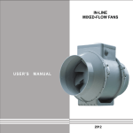
IN-LINE MIXED-FLOW
FANS
VENTS TT PRO
USER'S MANUAL
www.ventilation-system.com
2012
!
ATTENTION
Deenergize the fan power circuit prior to all connection, adjustment, servicing and repair operations.
Mounting and maintenance are allowed by duly qualified electricians with valid electrical work permit for
electric operations at the units up to 1000 V after careful study of the present user's manual.
The single-phase power grid must comply with the acting local electrical norms and standards.
The fixed electrical wiring must be equipped with an automatic circuit breaker.
The fan must be connected to power mains through an automatic circuit breaker integrated into the
fixed wiring system with the gap between the breaker contacts on all poles not less than 3 mm.
Check the fan for any visible damages of the impeller and the casing before starting installation.
The casing internals must be free of any foreign objects which can damage the impeller blades.
Misuse of the product or any unauthorized modification is not allowed.
The fan is not to be used by children and persons with reduced physical, mental or sensory capacities,
without proper practical experience or expertise, unless they are controlled or instructed on the product
operation by the person(s) responsible for their safety. Do not leave children unattended and do not
let them play with the product.
Take steps to prevent ingress of smoke, carbon monoxide and other combustion products into the room
through open chimney flues or other fire-protection devices. Sufficient air supply must be provided for
proper combustion and exhaust of gases through the chimney of fuel burning equipment to prevent
back drafting.
Transporting medium must not contain any dust or other solid impurities, sticky substances or
fibrous materials. Do not use the fan in the environment containing hazardous or explosive materials
and vapours, i.e. spirits, gasoline, insecticides, etc. Do not close or block the fan intake or extract vents
in order to ensure the most effective air passage. Do not sit on the fan and do not put objects on the fan.
Fulfill the requirements stated in this user's manual to ensure long service life of the product.
Recycle at the end of the service life.
Do not dispose the product with unsorted
municipal trash.
2
Read the present user's manual carefully before proceeding with installation works.
Compliance with the manual requirements ensures reliable operation and long
!
service life of the product. Keep the user's manual available as long as you use
the product. You may need to re-read the information on the product servicing.
ATTENTION
DELIVERY SET
The delivery set includes:
1. Fan - 1 pce;
2. Screws and dowels - 4 pcs;
3. Plastic screwdriver (only for modifications with timer) - 1 pce;
4. User's manual;
5. Packing box.
SHORT DESCRPTION
The product described herein is a mixed-flow inline fan for supply or extract ventilation of premises
heated during winter time.
The fan is rated for connection to 100, 125, 150, 160, 200, 250 and 315 mm.
The fan is equipped with a two-speed motor.
VENTS TT PRO XXX - basic modification;
VENTS TT PRO XXX V - modification with a built-in speed switch;
VENTS TT PRO XXX RV - modification with a built-in speed switch and power cable with a plug (fig. 32);
VENTS TT PRO XXX T - modification with a off-delayed timer regulated from 2 to 30 minutes (fig. 31);
VENTS TT PRO XXX U(U1) - modification with a speed controller with electronic thermostat,
built-in temperature sensor and power cable with a plug (fig. 33);
VENTS TT PRO XXX Un (U1n) - modification with a speed controller with electronic thermostat,
external temperature sensor and power cable with a plug (fig. 33);
VENTS TT PRO XXX P - modification with a speed controller and a power cord with a plug (fig. 34).
XXX - spigot diameter.
Due to constant improvements the design of some models may slightly differ from that one described in this manual.
3
OPERATION RULES
The fan is rated for connection to single-phase AC 220-240 V / 50/60 Hz power mains.
The fan is designed for continuous operation always connected to power mains.
Air motion direction in the system must match the pointer on the fan casing.
Ingress protection rating IP X4.
The fan is rated for operation at the ambient temperature ranging from +1°C up to +45°C.
The transporting medium temperature must not exceed +60°C.
ELECTRONICS CONTROL LOGIC
The fan with the timer T is turned into operation after control voltage is supplied by the external switch
(e.g., by the light switch) to the input terminal LT. After the control voltage is off the fan continues to
operate within the timer period set by the timer from 2 to 30 minutes.
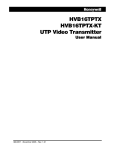
To adjust there off-delay timer rotate the potentiometer control knob T clockwise to increase and
counter-clockwise to decrease the off-delay time respectively (fig. 31).
Warning! The timer circuit is under mains voltage. All adjustments are allowed after disconnection from
power mains. The fan delivery set includes a specially designed plastic screwdriver for fan settings
adjustments. Use the screwdriver to alter the turn-off delay time or the humidity threshold.
Do not use a screwdriver, knife, etc. for adjustment operations not to damage the circuit board.
The fan model TT PRO U(U1) (fig. 33) is equipped with electronic TSC module (speed controller with
electronic thermostat) for automatic fan speed (air flow) control depending on air temperature.
The electrical compartment incorporates 2 control knobs:
for setting the motor speed;
for setting the electronic thermostat.
The fan cover incorporates a LED-light thermostat indicator.
To adjust the thermostat set point rotate the thermostat control knob clockwise to increase the set
point and counter clockwise to decrease the thermostat set point. To adjust the fan speed (air flow) rotate
the speed control knob in the same way.
The fan has two operating logics - temperature-based and timer-based operating logics.
temperature-based operating logic (TT PRO U):
This logic is used to keep air temperature to within 2°C. In this case the fan switches are rare.
The motor sets to maximum speed as the temperature reaches the thermostat set point.
The fan runs with the speed set by the speed controller if the temperature drops 2°C below the set point or
if the initial temperature us below the set point.
4
timer-based operating logic (TT PRO U1):
This logic is used for exact air temperature control. The motor changes its speed more often as
compared to the temperature pattern, but one speed interval continues at least 5 minutes.
The motor sets to maximum speed as the temperature reaches the thermostat set point.
If the temperature drops below the set thermostat point, the motor sets to set by the speed controller
speed 5 min. after the timer countdown. If the initial temperature is less, the motor starts operating
at set speed immediately.
The fan TT PRO P (fig. 34) is equipped with a speed controller that enables switching the fan on/off,
smooth speed (air flow) regulation from minimum to maximum value.
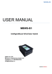
MOUNTING
The fan is suitable both for horizontal or vertical mounting on the floor, on the wall or on the ceiling
(fig. 2) as one unit or included into connected in parallel or in series sets (fig. 3).
In case of the horizontal fan mounting install a straight air ducts segment on side of the intake vent
not less than 1 m; in case of the vertical fan mounting install an outer hood to prevent water ingress
inside the fan. The exhaust pipe must be connected to the air duct.
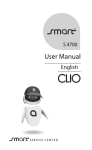
The mounting sequence is shown in fig. 4-12 and 25-30.
Wiring diagrams are shown in fig. 13-24.
Designation of the automatic circuit
breaker on wiring diagram
Automatic
circuit breaker
QF
Designations:
L1 - low speed terminal;
L2 - high speed terminal;
QF - automatic circuit breaker;
S - external speed switch;
ST - external switch (e.g., light switch);
X - input terminal.
Designation of the external
switch on wiring diagram
S
External switch
S/ST
1
5
MAINTENANCE
Clean the product surfaces regularly (once in 6 months) from dust and dirt (fig. 35-42).
Disconnect the fan from power mains prior to any maintenance operations.
To clean the fan use a soft cloth and a brush wetted in a mild detergent water solutions.
Avoid water dripping on the electric components (fig. 41). Wipe the surfaces dry after cleaning.
STORAGE AND TRANSPORTATION RULES
Transport the product by any transportation vehicle in the original manufacturer's package.
Store the delivered product in the manufacturer's original packing box in a dry ventilated premise with the
temperature range from +50C up to + 400C and relative humidity less than 80%.
The storage environment must not contain dust, acid or alkali vapours that may cause corrosion of the
product parts.
WARRANTY
The fan is manufactured at the factory of "Ventilation systems" PrJSC (hereinafter referred to as the
Manufacturer).
By purchasing this product the customer confirms to have read and agreed to the terms, rules and
requirements related to operation, storage, transportation, mounting, adjustment, connection,
maintenance and repair as well as warranty obligations with respect to this product as set forth in the
manufacturer's accompanying documentation to the product.
6
The manufacturing company sets forth the warranty period (service life) of the product as 24 months
following the sale date via retail network subject to the customer's ensuring compliance with the rules
of transportation, storage, mounting and operation of the product.
In case of any malfunction of the product through the fault of the Manufacturing company within the
warranty period (service life), the customer shall have the right to elimination of the manufacturing
defects by means of warranty servicing performed free of charge.
The warranty servicing implies performance of activities related to elimination of defects in the product
aimed to provide intended use of the product by the customer. The defects are eliminated either by
replacing or repairing such a product or a part (component) thereof.
With the purpose of performing warranty servicing please contact the trade company where you
purchased the product. If warranty servicing on the spot proves impossible, you will be provided with
the necessary information regarding rendering of this service.
Manufacturer's warranty shall not apply in the following cases:
- in case the customer fails to provide the product in complete according to the package contents specified
- in the User Manual or other relevant substituting document, including any components disassembled
by the customer;
- in case of incompliance of the model or marking of the product with data specified on the product
packaging and in the User Manual or other relevant substituting document;
- in case of non-timely technical maintenance of the product by the customer (dust, mud, oil condensate,
foreign particles);
- in case of causing external damage to the product by the customer ('damage' shall not apply to external
changes of the product required for the product mounting);
- in case of altering the product design or further reworking of the product;
- in case of replacing and using parts, units and components of the product not prescribed by the
manufacturing company;
- in case of other use of the product other than intended use;
- in case of the customer's violating product operation rules;
- in case of connecting the product to electric mains of voltage exceeding voltage value specified in the
User Manual;
- in case of step voltage that resulted in the product failure;
- in case of the customer's performing unauthorised repair of the product;
- in case of performing repair of the product by third persons unauthorized by the manufacturing company;
- in case of warranty period (service life) expiry;
- in case of the customer's violating transportation rules assuring prevention of damaging and/or
destruction of the product;
- in case of the customer's violating product storage rules;
- in case of performing unlawful actions by third persons with respect to the product;
- in case of force majeure (fire, flood, earthquake, war, hostilities of any kind, blockade);
- in case of absent seals, provided such seals are prescribed by the User Manual or other relevant
substituting document;
- in case of unavailable warranty card;
- in case of unavailable payment document to confirm the purchase with indication of the sale date.
7
The manufacturing company shall be responsible for defects arising through its fault prior to the
moment of transferring the product to the ownership of the customer. The manufacturing company shall
not be responsible for defects arising after transferring the product to the customer and caused by
the customer's violating the rules of transportation, storage, assembly and operation of the product,
or by actions of third persons, an accident or force majeure circumstances.
The manufacturing company shall not be responsible for damage to health and property of the customer
caused by the customer's violating the User Manual or other relevant substituting document;
other use of the product by the customer other than its intended use, or by failure of the customer to
comply with warnings and other information on the product specified in the User Manual or other
relevant substituting document, or by the customer's violating the rules of transportation, storage,
mounting, maintenance and operation of the product.
8
min 1 м
2
3
9
MOUNTING
QF
10
4
5
6
7
8
10
9
11
12
11
TT PRO 100/125
X
X
N
14
MAX
QF
L1
L
MAX / MIN
X
X
L1
L
~
N
~
L2
N
N
15
L2
~
N
13
L
L2
N
QF
L
~
N
L1
S
QF
MIN
16
TT PRO 150/160/200/250/315
X
X
L1
QF
L
~
N
N
MAX
18
X
L1
X
QF
L1
L
~
N
12
MIN
L
~
MAX / MIN
L2
19
QF
N
17
S
L2
N
L2
N
20
L
~
N
TT PRO 100 T/125 T/150 T/160 T/200 T/250 T/315 T
X
X
QF
QF
N
N
N
N
~
L
L
ST
~
L
LT
L
ST
LT
L2
terminal block for 4 contacts
terminal block for 5 contacts
MAX
X
QF
N
~
L
LT
S
L2
L
L1
N
~
L
ST
S
L1
X
QF
N
L
~
L
N
L
ST
LT
LT
L1
L1
MIN
LT
terminal block for 4 contacts
X
QF
23
ST
terminal block for 5 contacts
MAX / MIN
N
22
N
~
L
L
ST
X
QF
N
N
21
terminal block for 4 contacts
terminal block for 5 contacts
X
N
~
L
L2
L1
24
13
QF
25
28
14
26
27
29
30
-
2 min
+
30 min
Х
31
MIN
STOP
MAX
32
15
ÒÒ PRO U (U1)
speed control
knob
ÒÒ PRO Un (U1n)
thermostat control
knob
33
~
~
~
min
speed control
knob
34
16
max
35
36
37
38
17
18
39
40
41
42
ACCEPTANCE INFORMATION
Fan is ready for using.
Acceptance stamp
Date of production
100
125
V
150
RV
TT PRO 160
200
Ò
250
P
1
n
U
315
Sold
(name of trade enterprise and stamp of the shop)
Date of sale
(mark the proper model only)
www.ventilation-system.com
V77EN-01