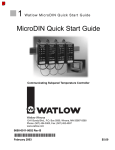
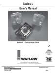
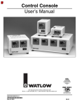
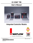
1
How to Reach Us
To be automatically connected to the nearest North American
Technical and Sales Office call:
E-SAFE® II Hybrid Power Switch
User’s Manual
1-800-WATLOW2
International Technical and Sales Offices:
Australia +61-3-9335-6449
China
+86-21-3950-9510
France +33 (01) 3073-2425
Germany +49 (0) 7253-9400-0
Italy
+39 (02) 458-8841
Japan
+81-3-3518-6630
Korea
+82-2-575-9804
Malaysia +60-3-7980-7741
Mexico +52 (442) 217-6235
Singapore +65-6777-1266
Spain
+34 916 751 292
Sweden +46 35-27-11-66
Taiwan +886-7-288-5168
United Kingdom +44 (0) 115-964-0777
Your Authorized Watlow Distributor:
1241 Bundy Boulevard, Winona, Minnesota USA 55987-5580
Phone: +1 (507) 454-5300 Fax: +1 (507) 452-4507
Internet: http://www.watlow.com
English
For other product information:
Watlow FAX REPLY: +1 (732) 885-6344, outside the U.S.; or +1 (800)
367-0430, inside the U.S.
0600-0055-0001 Rev C
June 2008
About Watlow
Watlow Electric Mfg. Co., has been manufacturing industrial electric
heating products since 1922 and is located in St. Louis, Missouri. Watlow
products include electric heaters, sensors, controllers and switching
devices. Watlow's facility in Winona, Minnesota has been designing
solid-state electronic control devices since 1962, and has earned the
reputation as an excellent supplier to original equipment manufacturers.
These OEMs and end users depend upon Watlow to provide compatibly
engineered controls that they can incorporate into their products with
confidence. The controls operation resides in a 100,000-square-foot
marketing, engineering and manufacturing facility in Winona, Minnesota.
Warranty
The Watlow ESAFE® II Hybrid Power Switch is warranted to be free of
defects in material and workmanship for 24 months after delivery to the
first purchaser for use, providing that the units have not been misapplied.
Since Watlow has no control over their use, and sometimes misuse, we
cannot guarantee against failure. Watlow's obligations hereunder, at
Watlow's option, are limited to replacement, repair or refund of purchase
price, and parts which upon examination prove to be defective within
the warranty period specified. This warranty does not apply to damage
resulting from transportation, alteration, misuse, or abuse.
Returns
• Call or fax your distributor or the nearest Watlow sales office for best
information about returns. (See outside back cover.)
• To return directly to Watlow in the U.S., first call or fax Customer
Service for a Return Material Authorization (RMA) number
(telephone: +1 (507) 454-5300; fax: +1 (507) 452-4507).
Multiple U.S. and international patents pending.
Safety Information
ç
CAUTION or
WARNING
Ó
Electrical
Shock Hazard
CAUTION or
WARNING
We use note, caution and warning symbols throughout this
book to draw your attention to important operational and
safety information.
A “NOTE” marks a short message to alert you to an important
detail.
A “CAUTION” safety alert appears with information that is
important for protecting your equipment and performance. Be
especially careful to read and follow all cautions that apply to
your application.
A “WARNING” safety alert appears with information that
is important for protecting you, others and equipment from
damage. Pay very close attention to all warnings that apply to
your application.
The safety alert symbol, ç (an exclamation point in a triangle) precedes a general CAUTION or WARNING statement.
The electrical hazard symbol, Ó (a lightning bolt in a
triangle) precedes an electric shock hazard CAUTION or
WARNING safety statement.
Technical Assistance
If you encounter a problem with your Watlow controller,
review your configuration information to verify that your
selections are consistent with your application: inputs; outputs; alarms; limits; etc. If the problem persists after checking
the configuration of the controller, you can get technical assistance from your local Watlow representative (see back cover),
or in the U.S., dial +1 (507) 494-5656.
Please have the following information available when calling:
• Put the RMA number on the shipping label, along with on a written
description of the problem.
• Complete model number
• A restocking charge of 20% of the net price is charged for all standard
units returned to stock.
Your Comments
Quality and Mission Statement:
Watlow will be the world’s best supplier of superior thermal solutions by exceeding the expectations of our customers, shareholders, and employees.
• User’s Manual
We welcome your comments or suggestions on this user’s
manual. Please send them to: Technical Writer, Watlow, 1241
Bundy Blvd., P.O. Box 5580, Winona, Minnesota, USA 559875580; telephone: +1 (507) 454-5300; fax: +1 (507) 452-4507. ©
Copyright 2007 by Watlow, Inc. All rights reserved.
Neutral
L3
L3
240VÅ L2
480VÅ L2
L1
Fuse
Breaker
Series SD
SD3_-_K_ _-_ _RG
1 2 3 4 5 6
L1
Fuse
Input
120V Å
A1 A2
CR1
L3
5
L2
3
T2
4
T1
2
T3
6
L3
5
E-SAFE® II
Hybrid Power
Switch
ES2X-3XX0-0000
120VÅ
Series SD
SD3_-_K_ _-_ _RG
1 2 3 4 5 6
L2
3
L1
1
7
E-SAFE® II
Hybrid Power
Switch
ES2X-2XX0-0000
Delta
Connected
Heater
Fuse
Fuse
Fuse
Fuse
480VÅ
L1
1
7
120VÅ
8 9 10 11
Breaker
CR1
240VÅ
Input
120V Å
8 9 10 11
A1 A2
T2
4
T1
2
T3
6
T3
N
4-Wire Wye
Connected Heater
Fuse
Fuse
T2
T1
4-Wire Wye
Connected Heater
Series LV
LVC6KW-4542500A
Reset
1
2
6
7
3
8
4
5
T3
Control
Thermocouple
CR1
Coil
Fuse
Reset
High Limit
Thermocouple
T2
9
10
Wye
T1
Connected
Heater
Series LV
LVC6KW-4542500A
1
2
CR1
Coil
6
7
3
Fuse
8
4
5
9
10
Fuse
System Wiring Example 240 volt, 3-phase, 3 pole
with ac input control
Note:
ES2X-2XX0-0000 is powered via L1, L2
N
High Limit
Thermocouple
Control
Thermocouple
Fuse
System Wiring Example 277/480 volt, 3-phase, 3
pole with ac input control, 4-wire Wye connected
heater only
Note:
ES2X-3XX0-0000 is powered via terminal (7) and L1
240VÅ L2
120VÅ L1
L1
Breaker
L1
1
7
Input
120V Å
8 9 10 11
Fuse
Fuse
A1 A2
T1
2
T2
4
Series SD
SD3_-_K_ _-_ _RG
T3
6
1 2 3 4 5 6
E-SAFE® II
Hybrid Power
Switch
ES21-1HV0-0000
Series LV
LVC6KW-4542500A
1
2
3
4
5
6
7
8
Control
Thermocouple
CR1
Coil
Fuse
Reset
High Limit
Thermocouple
1
2
4
5
System Wiring Example 120 volt, single-phase, 1
pole with ac input control
6
7
8
A1 A2
T1
2
L3
5
L2
3
T2
4
T3
6
E-SAFE® II
Hybrid Power
Switch
ES22-2HV0-0000
Control
Thermocouple
CR1
Coil
Fuse
High Limit
Thermocouple
9
10
Fuse
Input
120V Å
8 9 10 11
L1
1
7
120VÅ
Series LV
LVC6KW-4542500A
3
9
10
CR1
Fuse
Fuse
Reset
Fuse
240VÅ
L3
5
L2
3
Series SD
SD3_-_K_ _-_ _RG
1 2 3 4 5 6
Fuse
Breaker
CR1
Fuse
System Wiring Example 240 volt, single-phase, 2
pole with ac input control
ç∫
WARNING:
Wiring must conform to National Electric Code (NEC) safety standards, as well as locally applicable codes. Failure to do so could result in
personal injury or loss of life. See the product rating curve for wire gauge selection, ambient temperature and current restrictions.
∫
WARNING:
Only authorized and qualified personnel should install and service the E-SAFE II Hybrid Power Switch. Failure to comply with these recommendations may result in damage to equipment and property and injury to personnel.
Torque Guidelines:
Properly torque line and load terminals to 2.25 nm (20 in-lbs).
NOTE:
Do not use an RC snubber on the temperature control command signal output. The leakage current through
a snubber circuit can turn the E-SAFE II relay on, even when the command signal is off.
Snubbers
Snubbers
Snubbers
U.L. Conditions of Acceptability
Applications must be tested as described below for specific wire insulation or specific wire gauge sizes. Tests
shall be performed in the end application under worstcase operating conditions.
Test Procedure
A.
B.
Monitor the temperature of terminals, using
thermocouples between the ring terminal and
connectors L1, L2 or L3. The temperature must
not exceed 95°C.
Monitor the temperatures of wire insulation,
using a thermocouple located 3 inches from the
connector. The temperature must not exceed the
insulation rating of the wire.
ç∫
WARNING: Thermocouples attached to terminals will be at load
voltage potential, measurements need to be taken with isolated
equipment or isolate the sensor from the terminal with suitable
insulation.
These ratings apply to 3-phase units with cycle times of 30 seconds or more. Consult the factory for 1- and 2-phase unit ratings.
ç∫
ç∫
WARNING: Wiring must conform to National Electric Code (NEC)
safety standards, as well as locally applicable codes. Failure to do
so could result in personal injury or loss of life.
WARNING: Do not use an ungrounded wye- or delta-wired heater
configuration at 400 or 480VÅ (ac).
See the product rating curve for wire gauge selection, ambient temperature and current restrictions.
Failure to follow all specifications and wiring instructions may result
in property damage, personal injury and/or loss of life.
ç
∫
WARNING: Only authorized and qualified personnel should install
and service the E-SAFE II Hybrid Power Switch. Failure to comply
with these recommendations may result in damage to equipment
and property and injury to personnel.
CAUTION: Provide proper enclosure ventilation to maintain an operating environment less than 70°C (158°F) maximum ambient rating.
Failure to do so could cause damage to equipment and property.
Torque Guidelines:
Properly torque line and load terminals to 2.25 nm (20
in-lbs).
Unit Dimensions
6.35 mm
(0.25 in)
Side
Top
46.99 mm
(1.85 in)
23.88 mm
(0.94 in)
97.03 mm
(3.82 in)
82.55 mm
(3.25 in)
14.88 mm
(0.586 in)
48.51 mm
(1.910 in)
140.72 mm
(5.54 in)
#10-32 (7x)
1/4 x 0.032
male Q.D. (2x)
holes and slots for fit
with #10 screws
Specifications
Ordering Information
Output voltage
• 100/120VÅ (ac) +10/-15 percent, 50/60Hz
• 200/240VÅ (ac) +10/-15 percent, 50/60Hz
• 230/277VÅ (ac) +10/-15 percent, 50/60Hz
Output amperage
• Up to 35 amperes single, dual and three-phase
• 30 A @ 277VÅ (ac)
Operating environment
• 0 to 70°C (32 to 158°F) operating temperature
• 0 to 90 percent RH, non-condensing
• Operational life: Four million switching cycles
• Installation category III, Pollution degree 2
Control mode
• “No-arc” hybrid contactor
Input command signal
• 3 to 32VÎ (dc), 24VÅ (ac) +20/-20 percent
• 100 to 240VÅ (ac) +10/-15 percent, [85 to 264VÅ (ac)]
Input command signal terminals
• 1⁄4 inch fast on appliance
Line and load terminals
• No. 10 screw will accept ring terminals, locking fork terminals or block
fork terminals, 1⁄4 in. (6.35 mm) by 10-32
• Wire insulation temperature can be determined through testing
described in the U.L. Conditions of Acceptability.
ES2_ -___0-0___
Number of Poles
1 1 pole
2 2 poles controlled
3 3 poles controlled
Load Voltage
1 100 to 120VÅ (ac)
2 200 to 240VÅ (ac)
3 230/277VÅ (ac) (400/480VÅ (ac) with
wye/star, neutral connected to center
required)
Command Signal Voltage
LV Low voltage 3 to 24VÎ (dc) or 24VÅ (ac)
HV High voltage 100 to 240VÅ (ac) +10/-15
percent, [85 to 264VÅ (ac)]
Future Option
Future Option
Custom Parameters
000 Standard product
Mounting
• Back panel mount
• Horizontal or vertical mounting options with equal product
performance
NOTE:
Do not use an RC snubber on the temperature control
command signal output. The leakage current through
a snubber circuit can turn the E-SAFE II relay on, even
when the command signal is off.
Snubbers
Declaration of Conformity
Series Esafe II Relay
Watlow Winona, Inc.
1241 Bundy Blvd.
Winona, MN 55987 USA
Declares that the following product:
Designation:
Model Numbers:
Classification:
Rated Voltage and Frequency:
Rated Power Consumption:
Series Esafe II Relay
ES2 (1, 2 or 3) – (1, 2 or 3)(LV or HV)0 – 0 (any three letters or numbers)
AC51 Semiconductor Direct-on-line contactor,
Installation Category III, Pollution degree 2, IP00
100-120 Vac, 200-240 Vac, 230-277 Vac*
*Star or Wye with Center connected Neutral required.
35A Resistive Load Maximum
Meets the essential requirements of the following European Union Directives by using the relevant standards show
below to indicate compliance.
2004/108/EC Electromagnetic Compatibility Directive
EN 60947-4-1
EN 60947-4-3
2004
2000
CRGD,
2005
EN
EN
EN
EN
EN
EN
EN
1996
2002
2004
1995
1996
1994
2004
A2, 2001
61000-4-2
61000-4-3
61000-4-4
61000-4-5
61000-4-6
61000-4-8
61000-4-11
A2, 2001
A3, 2005
A1, 2001
Low-Voltage switchgear and controlgear Part 4-3: Contactors and
motor-starters AC semiconductor controllers and contactors for
non-motor loads. Class B Emissions
Electrostatic Discharge Immunity
Radiated Field Immunity
Electrical Fast-Transient / Burst Immunity
Surge Immunity
Conducted Immunity
Magnetic Field Immunity
Voltage Dips, Short Interruptions and Voltage Variations Immunity
IEC 61000-3-12
2004
Harmonic Current Emissions > 16A < 75A
2
IEC 61000-3-11
2000
Voltage Fluctuations and Flicker > 16A < 75A
NOTE 1: To comply with flicker requirements cycle time may need to be greater than 12 seconds if Load
Power is = 16A to comply with standard, or the maximum source impedance needs to be determined. Source
impedance shall meet EN 61000-3-11 requirements for load currents > 16A.
2
2006-95-EC Low-Voltage Directive
EN 60947-1
EN 60947-4-3
2004
2000
CRGD,
2005
Low-Voltage switchgear and controlgear Part 4-3: Contactors and
motor-starters AC semiconductor controllers and contactors for
non-motor loads.
Compliant with 2002/95/EC RoHS Directive
2002/96/EC WEEE Directive
Equipment Requires Recycling
Raymond D. Feller III
Name of Authorized Representative
Winona, Minnesota, USA
Place of Issue
General Manager
Title of Authorized Representative
February 2008
Date of Issue
Signature of Authorized Representative