
1
L2K1500
USER MANUAL
020-000387-01
✽ Lens not included.
User’s Manual
Features and Design
This Multimedia Projector is designed with most advanced technology for portability, durability, and
ease of use. This projector utilizes built-in multimedia features, a palette of 1.07 billion colors, and matrix
liquid crystal display (LCD) technology.
◆
Functionally Rich
◆
Projection lens can be moved up, down, right and
left with the motor-driven lens shift function. This
function makes it easy to provide projected image
where you want. Zoom and focus can also be
adjusted with a motor-driven operation. (p.28)
*Z oom and focus functions may not operate
depending on the optional lens.
This projector has many useful functions such
as lens shifting, ceiling and rear projection,
perpendicular omnidirectional projection, variety of
lens options, etc. ◆
Simple Computer System Setting
The projector has the Multi-scan system to
conform to almost all computer output signals
quickly (p.35). Supported resolution up to WUXGA.
◆
◆
Power Management
The Power management function reduces power
consumption and maintains lamp life (p.63).
◆
Picture-in-Picture
This projector is capable of projecting two images
simultaneously by using either built-in picture-inpicture mode or picture-by-picture mode (pp.56-57).
◆
Multilanguage Menu Display
Operation menu is available in 12 languages;
English, German, French, It alian, Spanish,
Portuguese, Dutch, Swedish, Russian, Chinese,
Korean, and Japanese (p.54).
◆
Hot-Swap Lamps
Hot-swap lamps enable you to replace the failed
lamp with a new one without turning off the
projector.
Shutter Function
The projector is equipped with the shutter that
provides complete blackness for a while the
projected image is not needed with keeping the
projector on. The Shutter management function
allows you to set the timer. It prevents leaving
the projector on with the shutter closed for a long
time. (p.66)
Security Function
The Security function helps you to ensure security
of the projector. With the Key lock function, you can
lock the operation on the side control or remote
control (p.64). PIN code lock function prevents
unauthorized use of the projector (pp.64–65).
◆
Motor-driven Lens Shift
◆
Multi Versatile Platform
This projector applies various input/output
terminals and 2 terminal slots for expansion to
tune to diversity of signals from computers and
video equipment (pp.19-21). For optional interface
boards, contact sales dealer where you purchased
the projector.
◆ Wired
LAN Function
This projector is loaded with a wired LAN function
to control and set-up the projector remotely via
network. For details, refer to the user’s manual
“Network Set-up and Operation”.
◆ Active
Maintenance Cleaner (AMC) unit
The built-in filter cleaning unit with a brush
automatically removes large particles from the
mesh filter, and the electrostatic honeycomb filter
and electrostatic pleated filter capture medium
and small particles. In addition, with the use of the
smoke resistant filter (optional), you can filter out
even oil smoke.
✔Note:
•The On-Screen Menu and figures in this manual may differ slightly from the product.
•The contents of this manual are subject to change without notice.
2
L2K1500 User Manual
020-000387-01 Rev.1 (05-2011)
Table of Contents
Features and Design . . . . . . . . . . . . . . . .
Table of Contents . . . . . . . . . . . . . . . . . . .
To The Owner . . . . . . . . . . . . . . . . . . . . . .
Safety Instructions . . . . . . . . . . . . . . . . .
2
3
4
5
Air Circulation
6
Installing the Projector in Proper Directions
7
Moving the Projector
8
Compliance . . . . . . . . . . . . . . . . . . . . . . . 9
Part Names and Functions . . . . . . . . . . 10
Front
10
Back
10
Bottom
10
Terminals and Connectors
11
Side Control and Indicators
12
Side Control
12
Indicators
13
LAMP 1/2/3/4 REPLACE indicators
13
Remote Control
14
Remote Control Battery Installation
15
Remote Control Receivers and Operating Range
15
Wired Remote Control
15
Remote Control Codes
16
Installation . . . . . . . . . . . . . . . . . . . . . . . 17
Input Selection . . . . . . . . . . . . . . . . . . . . 33
Direct Operation
33
Computer Input Source Selection
34
Video Input Source Selection
35
Computer Input . . . . . . . . . . . . . . . . . . . 36
Computer System Selection
36
Auto PC Adjustment
37
Manual PC Adjustment
38
Image Selection
40
Image Adjustment
41
Screen Size Adjustment
44
Video Input . . . . . . . . . . . . . . . . . . . . . . . 47
Video System Selection
47
Image Selection
48
Image Adjustment
49
Screen Size Adjustment
52
Settings . . . . . . . . . . . . . . . . . . . . . . . . . 54
Settings
54
How To Overlap the Projection Images . . . 70
How to Overlap the Projection Images on a Screen 70
Maintenance and Care . . . . . . . . . . . . . 72
Maintaining the AMC unit
72
Replacing the Filters
73
74
Lens Installation
17
Resetting the Filter Counter
Positioning Projector
17
Lamp Management
75
Picture Level and Pitch Adjustment
17
Lamp Replacement
76
Lens Shift Adjustment
18
Cleaning the Projection Lens
78
Terminals of Projector
19
Cleaning the Projector Cabinet
78
Connecting to Computer
20
Warning Indicators
79
Connecting to Video Equipment
21
Attaching the Cable Tie
22
Troubleshooting
80
Connecting the AC Power Cord
23
Menu Tree
83
Indicators and Projector Condition
86
Basic Operation . . . . . . . . . . . . . . . . . . . 24
Appendix . . . . . . . . . . . . . . . . . . . . . . . . 80
Turning On the Projector
24
Compatible Computer Specifications
89
Turning Off the Projector
25
Supported Signal Format for Optional Board
91
How to Operate the On-Screen Menu
26
Technical Specifications
92
Main Menu 27
Optional Parts
93
Operating with Projector Control
28
PJ Link Notice
93
Operating with Remote Control
29
Configurations of Terminals
94
32
PIN Code Number Memo
95
Dimensions
96
List of Picture in Picture
97
Keystone Correction
Trademarks
Each name of corporations or products in this book is either a registered trademark or a trademark of its respective corporation.
L2K1500 User Manual
020-000387-01 Rev.1 (05-2011)
3
To The Owner
Before installing and operating the projector, read this
manual thoroughly.
The projector provides many convenient features and
functions. Operating the projector properly enables you to
manage those features and maintains it in good condition for
many years to come.
Improper operation may result in not only shortening the
product life, but also malfunctions, fire hazard, or other
accidents.
If your projector seems to operate improperly, read this
manual again, check operations and cable connections and
try the solutions in the “Troubleshooting” section in the
back of this manual. If the problem still persists, contact the
dealer where you purchased the projector or the service
center.
CAUTION
RISK OF ELECTRIC SHOCK
DO NOT OPEN
CAUTION:TO REDUCE THE RISK OF ELECTRIC
SHOCK, DO NOT REMOVE COVER (OR
BACK). NO USER-SERVICEABLE PARTS
INSIDE EXCEPT LAMP REPLACEMENT.
REFER SERVICING TO QUALIFIED SERVICE
PERSONNEL.
THIS SYMBOL INDICATES THAT DANGEROUS
VOLTAGE CONSTITUTING A RISK OF ELECTRIC
SHOCK IS PRESENT WITHIN THIS UNIT.
THIS SYMBOL INDICATES THAT THERE ARE
IMPORTANT OPERATING AND MAINTENANCE
INSTRUCTIONS IN THE USER’S MANUAL WITH
THIS UNIT.
Safety Precaution
WARNING: lTHIS APPARATUS MUST BE EARTHED.
lTO REDUCE THE RISK OF FIRE OR ELECTRIC
SHOCK, DO NOT EXPOSE THIS APPLIANCE TO
RAIN OR MOISTURE.
– This projector produces intense light from the projection lens.
Do not stare directly into the lens, otherwise eye damage could
result. Be especially careful that children do not stare directly
into the beam.
– Install the projector in a proper position. Otherwise it may
result in a fire hazard.
– Allowing the proper amount of space on the top, sides, and
rear of the projector cabinet is critical for proper air circulation
and cooling of the unit. The diagrams shown here indicates the
minimum space required. If the projector is to be built into a
compartment or similarly enclosed, these minimum distances
must be maintained.
SIDE and TOP
REAR
3.3' (1m)
3.3' (1m)
3.3' (1m)
– Do not cover the ventilation slots on the projector. Heat buildup can reduce the service life of your projector, and can also be
dangerous.
– If the projector is unused for an extended time, unplug the
projector from the power outlet.
– Do not project the same image for a long time. It may be
burned into the LCD panels.
CAUTION ON HANGING FROM THE CEILING
FOR EU USERS
The symbol mark and recycling systems described below
apply to EU countries and do not apply to countries in other
areas of the world.
Your product is designed and manufactured with high quality materials and components which can be recycled and/or
reused.
The symbol mark means that electrical and electronic
equipment, batteries and accumulators, at their end-of-life,
should be disposed of separately from your household
waste.
Note:
If a chemical symbol is printed beneath the symbol mark,
this chemical symbol means that the battery or accumulator contains a heavy metal at a certain concentration. This
will be indicated as follows: Hg: mercury, Cd: cadmium, Pb:
lead.
In the European Union there are separate
collection systems for used electrical and
electronic equipment, batteries and accumulators.
Please, dispose of them correctly at your
local community waste collection/recycling
centre.
Please, help us to conserve the environment
we live in!
4
hen hanging the projector from the
W
ceiling, clean the air intake vent and
top of the projector periodically with a
vacuum cleaner. If you leave the projector
unclean for a long time, the cooling fans
can be clogged with dust, and it may
cause a breakdown or a disaster.
Do not set the projector in greasy, wet, or
smoky conditions such as IN a kitchen to
prevent A Breakdown or a disaster. If the
projector comes in contact with oil or
chemicals, it may become deteriorated.
CAUTION
Not for use in a computer room as defined in the
Standard for the Protection of Electronic Computer/Data
Processing Equipment, ANSI/NFPA 75.
READ AND KEEP THIS USER’S MANUAL FOR LATER
USE.
L2K1500 User Manual
020-000387-01 Rev.1 (05-2011)
Safety Instructions
All the safety and operating instructions should be read
before the product is operated.
Read all of the instructions given here and retain them for
later use. Unplug this projector from AC power supply
before cleaning. Do not use liquid or aerosol cleaners. Use a
damp cloth for cleaning.
This projector should be operated only from the type of
power source indicated on the marking label. If you are not
sure of the type of power supplied, consult your authorized
dealer or local power company.
Follow all warnings and instructions marked on the projector.
Do not overload wall outlets and extension cords as this
can result in fire or electric shock. Do not allow anything to
rest on the power cord. Do not locate this projector where
the cord may be damaged by persons walking on it.
For added protection to the projector during a lightning
storm, or when it is left unattended and unused for long
periods of time, unplug it from the wall outlet. This will
prevent damage due to lightning and power line surges.
Do not attempt to service this projector yourself as opening
or removing covers may expose you to dangerous voltage
or other hazards. Refer all servicing to qualified service
personnel.
Do not expose this unit to rain or use near water... for
example, in a wet basement, near a swimming pool, etc...
D o n o t u s e a tt a ch m e n t s n o t r e c o m m e n d e d by t h e
manufacturer as they may cause hazards.
Do not place this projector on an unstable cart, stand, or
table. The projector may fall, causing serious injury to a child
or adult, and serious damage to the projector. Use only with
a cart or stand recommended by the manufacturer, or sold
with the projector. Wall or shelf mounting should follow the
manufacturer's instructions, and should use a mounting kit
approved by the manufacturers.
An appliance and cart combination
should be moved with care. Quick
stops, excessive force, and uneven
surfaces may cause the appliance and
cart combination to overturn.
Slots and openings in the back and bottom of the cabinet are
provided for ventilation, to ensure reliable operation of the
equipment and to protect it from overheating.
Unplug this projector from wall outlet and refer servicing to
qualified service personnel under the following conditions:
a. When the power cord or plug is damaged or frayed.
b. If liquid has been spilled into the projector.
c. If the projector has been exposed to rain or water.
d. If the projector does not operate normally by following
the operating instructions. Adjust only those controls
that are covered by the operating instructions as
improper adjustment of other controls may result in
damage and will often require extensive work by a
qualified technician to restore the projector to normal
operation.
e. If the projector has been dropped or the cabinet has
been damaged.
f. When the projector exhibits a distinct change in
performance-this indicates a need for service.
When replacement parts are required, be sure the service
technician has used replacement parts specified by the
manufacturer that have the same characteristics as the
original part. Unauthorized substitutions may result in fire,
electric shock, or injury to persons.
Upon completion of any service or repairs to this projector,
ask the ser vice technician to perform routine safety
checks to determine that the projector is in safe operating
condition.
The openings should never be covered with cloth or other
materials, and the bottom opening should not be blocked
by placing the projector on a bed, sofa, rug, or other similar
surface. This projector should never be placed near or over a
radiator or heat register.
This projector should not be placed in a built-in installation
such as a book case unless proper ventilation is provided.
Never push objects of any kind into this projector through
cabinet slots as they may touch dangerous voltage points
or short out parts that could result in a fire or electric shock.
Never spill liquid of any kind on the projector.
NOTE FOR CUSTOMERS IN THE US
Hg LAMP(S) inside this product contain mercury
and must be recycled or disposed of according
to local, state or federal laws.
Do not install the projector near the ventilation duct of airconditioning equipment.
L2K1500 User Manual
020-000387-01 Rev.1 (05-2011)
5
Safety Instructions
Air Circulation
IMPORTANT!
Openings in the cabinet are provided for ventilation. To
ensure reliable operation of the product and to protect
it from overheating, these openings must not be
blocked or covered.
CAUTION
Hot air is exhausted from the exhaust vents. When
using or installing the projector, the following
precautions should be taken.
– Do not put any flammable object or spray can near
the projector, hot air is exhausted from the air vents.
– Keep the exhaust vents at least 3’ (1 m) away from
any objects.
– Do not touch peripheral parts of the exhaust vents,
especially screws and metallic parts. These areas will
become hot while the projector is being used.
– Do not put anything on the cabinet. Objects put on
the cabinet will not only get damaged but also may
cause fire hazard by heat.
– Do not cover vents with papers or other materials.
– Make sure that there are no objects under the
projector. An object under the projector may prevent
the projector from taking cooling air through bottom
vent.
– When detaching the adjustable feet, always keep at
least 50 mm between the bottom of the projector
and installation surface.
Cooling fans are provided to cool down the projector.
The fans’ running speed is changed according to the
temperature inside the projector.
EXHAUST VENTS
Filter Maintenance!!
The projector uses a lamp which generates
significant heat. The cooling fans and air vents are
provided to dissipate the heat by drawing air into the
housing and the filter is located in the intake vent to
prevent dust from getting inside of the projector.
In order to care for the projector appropriately,
regular cleaning is required. Remove any dirt or dust
that has accumulated on the projector.
If the projector reaches a time set in the timer
setting, the icon as shown in Fig. 1 appears on the
screen and WARNING FILTER indicator lights up (see
below), indicating that cleaning or replacing the filter
is necessary.
If the projector detects that the filter is clogged, the
icon as shown in Fig. 2 appears on the screen and
WARNING FILTER indicator lights up (see below).
Stop using the projector immediately and replace the
electrostatic honeycomb filter and the electrostatic
pleated filter.
Blocking the air vents and leaving the projector
uncleaned for a long time may not only damage the
projector and may require costly repairs but may also
cause accidents or fire.
For maintenance of the filter, refer to “Filter counter”
on page 68 and “Maintenance and Care” on pages
72-74.
Damages to the projector caused by using an
uncleaned filter or improper maintenance will
void the warranty on the projector.
Top Panel
Fig.1
AIR INTAKE VENT
(Bottom)
Fig.2
WARNING FILTER
indicator
6
L2K1500 User Manual
020-000387-01 Rev.1 (05-2011)
Safety Instructions
Installing the Projector in Proper Directions
Use the projector properly in specified positions. Improper positioning may reduce the lamp life and result in
severe accident or fire hazard.
This projector can project the picture in upward, downward, or inclined position in perpendicular direction to the
plane.
✔Note:
•To inverse or reverse the image, set the ceiling function to “On.” (pp. 46, 53)
•The projector can not be operated at an altitude above 3,000 meters.
Positioning Precautions
Avoid positioning the projector as described below when installing.
10˚
Do not roll the projector more
than 10 degrees from side to
side.
10˚
10˚
In upward projection, do
not tilt the projector over 10
degrees right and left.
10˚
In downward projection, do
not tilt the projector over 10
degrees right and left.
Do not put the projector
on either side to project an
image.
10˚
10˚
CAUTION ON CEILING MOUNTING
For ceiling mounting, you need the ceiling mount kit designed for this projector. When not mounted
properly, the projector may fall, causing hazards or injury. For details, consult your dealer. The warranty
on this projector does not cover any damage caused by use of any non-recommended ceiling mount kit
or installation of the ceiling mount kit in an improper location.
Cautious use of equipment with laser technology
Do not radiate strong light such as laser light on the projection lens directly, as this may degrade the
functionality of the projector. Failure to do so will void any applicable warranties.
L2K1500 User Manual
020-000387-01 Rev.1 (05-2011)
7
Safety Instructions
Moving the Projector
Retract the adjustable feet to prevent
damage to lens and cabinet. For
safety, holding the carrying handles
on both sides by 2 or more people is
recommended to move the projector
because the projector is heavy. Moving
it improperly may result in damage of
cabinet or person's injury.
CAUTION
IN CARRYING OR
TRANSPORTING THE PROJECTOR
–Do not drop or bump the projector, otherwise
damages or malfunctions may result.
–When carrying the projector, use a suitable
carrying case.
–Do not transport the projector by courier or any
other transport service in an unsuitable transport
case. This may cause damage to the projector. For
information about transporting the projector by
courier or any other transport service, consult your
dealer.
–Do not put the projector in a case before it is
cooled enough.
–Do not transport the projector with a replacement
lens installed.
8
L2K1500 User Manual
020-000387-01 Rev.1 (05-2011)
Compliance
Federal Communications Commission Notice
This equipment has been tested and found to comply with the limits for a Class A digital device,
pursuant to Part 15 of FCC Rules. These limits are designed to provide reasonable protection against
harmful interference when the equipment is operated in a commercial environment. This equipment
generates, uses, and can radiate radio frequency energy and, if not installed and used in accordance
with the instruction manual, may cause harmful interference to radio communications. Operation of
this equipment in a residential area is likely to cause harmful interference in which case the user will be
required to correct the interference at his own expense.
Do not make any changes or modifications to the equipment unless otherwise specified in the
instructions. If such changes or modifications should be made, you could be required to stop operation
of the equipment.
Canadian Radio Interference Regulations
This Class A digital apparatus meets all requirements of the Canadian ICES-003.
WARNING
This is a Class A product. In a domestic environment this product may cause radio interference in which
case the user may be required to take adequate measures.
AC Power Cord Requirement
The AC Power Cord supplied with this projector meets the requirement for use in the country you purchased it.
AC Power Cord for the United States and Canada:
AC Power Cord used in the United States and Canada is listed by the Underwriters
Laboratories (UL) and certified by the Canadian Standard Association (CSA).
AC Power Cord has a grounding-type AC line plug. This is a safety feature to be sure
that the plug will fit into the power outlet. Do not try to defeat this safety feature.
Should you be unable to insert the plug into the outlet, contact your electrician.
GROUND
THE SOCKET-OUTLET SHOULD BE INSTALLED NEAR THE EQUIPMENT AND EASILY ACCESSIBLE.
L2K1500 User Manual
020-000387-01 Rev.1 (05-2011)
9
Part Names and Functions
qLens Mount Cover
wAMC (Active Maintenance Cleaner) Unit
e Projection Lens (Optional)
rIndicators
tInfrared Remote Receivers (Front&Top)
y Terminals and Connectors
u Carrying Handles
i Side Control
Front
q
i
vKensington* Security Slot
This slot is for a Kensington lock used to
deter theft of the projector.
w
e
Back
rt
y
v
*Kensington is a registered trademark of ACCO Brands
Corporation.
u
o Exhaust Vents
!0 Lamp Covers
!1 Power Cord Connector
!2 Main On/Off Switch
!3 Infrared Remote Receiver (Rear)
!0
o
CAUTION
!1 !2
!3
Bottom
Hot air is exhausted from the exhaust
vents. Do not put heat-sensitive objects
near this side.
u
!4
!4 Adjustable Feet
!5 Air Intake Vent
!5
10
L2K1500 User Manual
020-000387-01 Rev.1 (05-2011)
Part Names and Functions
Terminals and Connectors
q
w
e
r
t
!0
o
i
qSERIAL PORT IN TERMINAL
If you control the projector from a computer, you
must connect a cable (not supplied) from your
computer to this RS-232C terminal.
wSERIAL PORT OUT TERMINAL
This terminal outputs signal from SERIAL PORT IN.
More than two projectors can be controlled with
one computer by connecting SERIAL PORT IN of
another projector to this RS-232C terminal.
u
y
u5 BNC JACK
Connects the component or composite video
output signal from video equipment to VIDEO/Y,
Pb/Cb, and Pr/Cr jacks or connect the computer
output signal (5 BNC Type [Green, Blue, Red,
Horiz. Sync, and Vert. Sync.]) to G, B, R, H/HV, and
V jacks (pp.20–21).
eUSB CONNECTOR (series B)
i ANALOG TERMINAL
Connects the computer (or RGB scart) output
signal to this terminal (pp.20–21).
rR/C JACK
oHDMI TERMINAL
USB connector is to used to service the projector.
When using the wired remote control, connect the
wired remote control to this jack with a remote
control cable (not supplied).
tLAN PORT
Connecting the Ethernet cable See the user’s
manual of “Network Set-up and Operation” for
details.
Connects the HDMI output signal from video
equipment to this terminal. (pp.20-21)
!0 DIGITAL (DVI-D) TERMINAL
Connects computer output (Digital/DVI-D type) to
this terminal (p.20).
HD (HDCP Compatible) signal can be also
connected (p.21).
yS-VIDEO JACK
Connects the S-VIDEO output signal from video
equipment to this jack (p.21).
L2K1500 User Manual
020-000387-01 Rev.1 (05-2011)
11
Part Names and Functions
Side Control and Indicators
Indicators
Terminal Lights Side Control
Side Control
q
i
w
e
o
r
t
!0
y
!1
u
qON/STAND-BY button
Turns the projector on or off. (pp.24,25)
wSHUTTER button
Closes and opens up the built-in shutter. (p.28)
!2
uAUTO PC ADJ. button
Automatically adjusts the computer image to its
optimum setting. (pp.28, 37)
iLIGHT button
Lights the side control and terminals. (p.28)
eZOOM button
Zooms in and out the images. (p.28)
oLENS SHIFT button
Selects the LENS SHIFT function. (p.28)
rFOCUS button
Adjusts the focus. (p.28)
!0INPUT button
Selects an input source Input 1, Input 2, Input 3 or
Input 4. (pp.33-35)
tMENU button
Opens or closes the On-Screen MENU. (pp.26, 27)
yPOINT buttons
-S
elect an item or adjust the value in the OnScreen MENU. (p.26)
-P
an the image in DIGITAL ZOOM + mode. (p.45)
12
!1 SELECT button
Used to execute the selected item. (p.26) It is also
used to make the image larger in DIGITAL ZOOM +
mode and smaller in DIGITAL ZOOM - mode. (p.45)
!2 INFORMATION button
Displays the input source information (p.28).
L2K1500 User Manual
020-000387-01 Rev.1 (05-2011)
Part Names and Functions
Indicators
q
w
e
r
t
y
qPOWER indicator
This indicator lights green when the projector
is ready to be turned on in standby mode. And
it flashes green in Power Management mode.
(pp.63, 86-88)
wLAMP Indicator
This indicator is dim when the projector is turned
on. And bright when the projector is in stand-by
mode. (pp.86-88)
eWARNING TEMP. indicator
This indicator flashes red when internal projector
temperature is too high. (pp.79, 86-88)
rWARNING FILTER indicator
– Lights orange when the clogging of the filter
is detected or the filter counter reaches a time
set in the timer setting, urging immediate filter
replacement. (pp.68, 73, 88)
– Blinks orange during a filter cleaning process.
tSHUTTER indicator
Lights blue when the shutter is closed. (p. 86)
y LAMP REPLACE indicator
Lights orange when any of the projection lamps
reaches its end of life. (pp.76, 87)
LAMP 1/2/3/4 REPLACE indicators
- When any of the LAMP 1/2/3/4 REPLACE indicators lights:
The corresponding lamp is approaching its end.
- When any of the LAMP 1/2/3/4 REPLACE indicators flashes:
The corresponding lamp needs to be replaced.
L2K1500 User Manual
020-000387-01 Rev.1 (05-2011)
13
Part Names and Functions
Remote Control
w
e
q
r
!5
t
!6
!7
y
!8
u
!9
@0
i
@1
o
!0
!1
!2
!3
@2
!4
@3
@4
@5
@6
14
qSTAND-BY button
Turns the projector off. (p.25)
wSIGNAL EMISSION indicator
Lights red while a signal is being sent from the remote control unit
to the projector.
eON button
Turns the projector on. (p.24)
rSHUTTER button
Closes the built-in shutter for light blocking. (pp.28, 29)
t MENU button
Opens or closes the On-Screen MENU. (pp.26, 27)
y Point ed 7 8 buttons
–Select an item or adjust the value in the ON-SCREEN MENU. (p.26)
–Pan the image in DIGITAL ZOOM +/– mode. (p.45)
uLENS SHIFT button
Selects the LENS SHIFT function. (p.29)
iZOOM buttons
Zoom in and out the images. (p.29)
oD.ZOOM button
Selects the Digital zoom +/- mode and resize the image. (pp.29, 45)
!0FREEZE button
Freezes the picture on the screen. (p.31)
!1KEYSTONE button
Corrects keystone distortion. (pp.32, 46, 53)
!2P-TIMER button
Operates the P-TIMER function. (pp.31, 69)
!3 INFO. button
Displays the input source information. (p.29)
!4 FILTER button
To schedule a filter cleaning task. (p.31)
!5SCREEN button
Selects the screen size. (pp.44-46, 52-53)
!6LIGHT button
Lights the buttons on the remote control for about 10 seconds.
!7AUTO PC button
Automatically adjusts the computer image to its optimum setting.
(pp.29, 37)
!8SELECT button
–Executes the selected item. (p.26)
–Expands or compress the image in the DIGITAL ZOOM +/-mode.
(p.45)
!9IMAGE ADJUST button
Enters the image level adjustment mode. (pp.29, 41-43, 49-51)
@0 FOCUS buttons
Adjusts the focus. (p.29)
@1IMAGE SEL. button
Selects the image level. (pp.31, 40, 48)
@2INPUT 1, 2, 3, and 4 buttons
Select an input source. (pp.33-35)
@3PIP button
Operates the Picture In Picture function. (p.31)
@4 ON/OFF switch
When using the remote control, set this switch to “ON”.
@5 Wired Remote Jack
Connects the remote control cable (not supplied) to this jack
when using as a wired remote control.
@6 Number buttons
Use these buttons when setting the remote control codes (p.16)
or when entering the PIN code numbers (pp. 24, 61, 65).
L2K1500 User Manual
020-000387-01 Rev.1 (05-2011)
Part Names and Functions
Remote Control Battery Installation
1
Open the battery
compartment lid.
2
Install new batteries into
the compartment.
3
Replace the
compartment lid.
Two AAA size batteries
For correct polarity (+ and –),
be sure battery terminals are
in contact with pins in the
compartment.
Pull up the lid
and remove it.
To ensure safe operation, please observe the following precautions :
● Use two (2) AAA or LR03 type alkaline batteries.
● Always replace batteries in sets.
● Do not use a new battery with a used battery.
● Avoid contact with water or liquid.
● Do not expose the remote control to moisture or heat.
● Do not drop the remote control.
● If the battery has leaked on the remote control, carefully wipe the case clean and install new batteries.
● Risk of an explosion if battery is replaced by an incorrect type.
● Dispose of used batteries according to the instructions or your local disposal rule or guidelines.
Remote Control Receivers and Operating Range
Point the remote control toward the projector (to Infrared
Remote Receivers). The operating distance and angle
between the receivers and the remote control must be
shorter than 16.4’ (5 m) and less than 60 degrees.
Infrared Remote Receivers are located on the front,
rear, and top panels. You can activate only necessary
receivers. (pp. 10, 63).
16.4’
(5 m)
✔Note:
• When hanging the projector from the ceiling, select the
Infrared Remote Receiver which is located farther away
from the fluorescent light (p.63).
• When placing the projector in the horizontal position, as
fluorescent light may negatively affect the remote control
signals, it is recommended to select either “Back” or
“Front” to prevent the receiver on top of the projector from
picking up the signals from the remote control. (p.63)
16.4’
(5 m)
Wired Remote Control
The remote control can be used as a wired remote control. Wired remote control helps you use the remote control outside
of the operating range (16.4’/ 5 m). Connect the remote control and the projector with the remote control cable (sold
separately). Connected with the remote control cable, the remote control does not emit wireless signal.
L2K1500 User Manual
020-000387-01 Rev.1 (05-2011)
15
Part Names and Functions
Remote Control Codes
When controlling several projectors from each remote control at the same time, you can assign a remote
control code (Code 1 - Code 8) to individual projectors and remote controls to prevent remote control
interference. Assign the same code the you specified for the projector to the remote control. See “Remote
Control” on page 62 for assigning a remote control code to the projector. Follow the procedures below to select
the assigned code.
Press and hold the MENU and a number button (1–8)
for more than five seconds to switch between the
codes. To reset it to the default code number (Code 1),
use the button combination of the MENU button and
the 0 number button ( press for 5 seconds).
MENU button
Number buttons
✔Note:
To ensure safe operation, observe the following precautions:
•Do not bend, drop, or expose the remote control to moisture or
heat.
•For cleaning, use a soft dry cloth. Do not apply benzene, thinner,
spray, or any other chemical materials.
16
L2K1500 User Manual
020-000387-01 Rev.1 (05-2011)
Installation
Lens Installation
Before setting up the projector, install Projection Lens on the projector.
efore installation, check where the projector is used and prepare a suitable lens. For the specifications of
B
Projection Lens, contact sales dealer where you purchased the projector.
- Lens installation and replacement should be performed by the qualified service personnel.
- When setting the projector after lens installation, be sure to replace a Lens Cap to protect a
surface.
- When carrying or holding up the projector, be careful not to put your hands on lens part. It may
damage lens, cabinet, or mechanical parts.
Positioning Projector
SCREEN
This projector is designed to project on a flat projection
surface.
✔Note:
• Brightness in room has a great influence on picture
quality. It is recommended to limit ambient lighting in
order to provide the best image.
Picture Level and Pitch Adjustment
The projection angle is adjustable up to 3 degrees upward
and downward respectively by rotating front and back feet
.
To raise the projector, rotate the feet clockwise.
To lower the projector or to retract the adjustable feet,
rotate the feet counterclockwise.
To correct keystone distortion, press the KEYSTONE
button on the remote control or select Keystone from the
menu (see pages 32, 46, 53).
Do not rotate the adjustable feet when you
see the red line on the adjustable feet. The
adjustable feet may fall off.
L2K1500 User Manual
020-000387-01 Rev.1 (05-2011)
Red line
Adjustable feet
ADJUSTABLE
FEET
17
Installation
Lens Shift Adjustment
Projection lens can be moved from side to side and up and down with the motor-driven lens shift function. This
function makes the positioning of images easy on the screen. (See page 28)
When the lens is shifted to top
The display position can be
shifted upward up to 50%
elevation of the display.
When the lens is shifted to leftmost
The display position can be
shifted to the left in up to
10% width of the display.
18
When the lens is shifted to bottom
The display position can be
shifted downward up to 50%
low level of the display.
When the lens is shifted to rightmost
The display position can be
shifted to the right in up to
10% width of the display.
L2K1500 User Manual
020-000387-01 Rev.1 (05-2011)
Installation
Terminals of Projector
The projector has two replaceable Interface board slots. The projector's functions can be extended by installing
the optional interface boards into the terminal slots. 2 vacant slots (Input 3 and 4) are provided in your
purchasing the projector. For the Optional Interface Boards, contact sales dealer where you purchased the
projector.
2 TERMINAL SLOTS (Factory set)
INPUT/OUTPUT
TERMINALS
Replacement of Terminal
✔Note:
• In the replacement of interface board, turn off the
projector, press the Main On/Off Switch to Off and
unplug the AC power cord from the AC outlet.
1
Remove 2 screws from an interface board.
2
Pull out the interface board.
3
Replace the interface board. Insert a new interface
4
Tighten screws to secure the interface board.
Screws
board along Guide to fit Socket to inside Plug.
Guide
NOTES ON ORDERING OR USING
OPTIONAL INTERFACE BOARD
Socket
When ordering or using Optional Interface Board, contact
your sales dealer. When contacting the sales dealer, tell the
Option Control Number (Op.cont.No.) in the menu that is
located on the bottom of the information menu.
(See page 29)
Plug
L2K1500 User Manual
020-000387-01 Rev.1 (05-2011)
As an example, this figure shows how to
install a Dual-SDI Board.
19
Installation
Connecting to Computer
Cables used for connection
• DVI-D cable
• Serial cross cable
• DVI/HDMI cable
• USB cable
• VGA Cable (D-sub 15 pin) *
( *One cable is supplied; Other cables are not supplied with this projector.)
• BNC Cable (BNC x 5)
Laptop type
Monitor Output
DVI-D Cable
Monitor Output
DVI/HDMI
VGA
Cable
Cable
DIGITAL
(DVI-D)
HDMI
ANALOG
Desktop type
Monitor Output
BNC Cable
G
B
Serial out USB port
Serial Cross
cable
R H/HV V
USB
cable
SERIAL PORT IN
USB
Terminals of
the projector
Unplug the power cords of both the
projector and external equipment from
the AC outlet before connecting cables.
20
L2K1500 User Manual
020-000387-01 Rev.1 (05-2011)
Installation
Connecting to Video Equipment
Cables used for connection
• Video Cable (BNC x 3, BNC x 1)
• HDMI Cable
• SCART-VGA Cable • DVI-D Cable
• S-Video Cable
( Cables are not supplied with the projector.)
Video Source (example)
Digital Output
(HDCP compatible)
DVI-D Cable
HDMI
Output
HDMI Cable
DIGITAL
(DVI-D)
Component video output equipment.
Video Disc Player
Professional Digital VCR
RGB SCART
21-pin Output
SCART-VGA
Cable
HDMI
Composite
Video
Output
BNC
Cable
(such as DVD player or
high-definition TV source.)
Component
Video Output
BNC
Cable
S-Video
Output
S-video
cable
ANALOG VIDEO VIDEO/Y, Pb/Cb, Pr/Cr S-VIDEO
Terminals of
the projector
Unplug the power cords of both the
projector and external equipment from the
AC outlet before connecting cables.
L2K1500 User Manual
020-000387-01 Rev.1 (05-2011)
21
Installation
Attaching the Cable Tie
Cable tie holders
You can dress and secure all cables to a cable tie (supplied).
The cable tie is reusable and can be loosened and tightened
as many times as needed.
To loosen the cable tie
Cable tie
2
1
Cable tie
2. Loosen the cable tie in the arrow direction.
Tab
1. Pull the tab in the arrow direction.
22
L2K1500 User Manual
020-000387-01 Rev.1 (05-2011)
Installation
Connecting the AC Power Cord
This projector uses nominal input voltages of 200-240 V AC. It
is designed to work with single-phase power systems having a
grounded neutral conductor. To reduce the risk of electrical shock,
do not plug into any other type of power system.
If you are not sure of the type of power being supplied, consult
your authorized dealer or service center.
Connect the projector with all peripheral equipment before turning
on the projector.
Holes
1
A power cord clamp is designed to prevent the AC power cord
from coming loose. Attach the power cord clamp and AC power
cord to the projector by following these steps.
1
Insert the both ends of the power cord clamp into the
holes and tilt the clamp.
2
Connect the AC power cord to the projector.
3
Secure the power cord connector with the clamp.
Power cord clamp
2
3
CAUTION
The AC outlet must be near this equipment and must be easily
accessible.
✔Note:
•Unplug the AC power cord or turn off the MAIN ON/OFF
Switch when the projector is not in use. When the projector
is in stand-by mode, it consumes a little electric power.
NOTE ON THE POWER CORD
AC power cord must meet the requirements of the country where you use the projector.
Confirm the AC plug type with the chart below and proper AC power cord must be used.
If the supplied AC power cord does not match your AC outlet, contact your sales dealer.
Projector side
AC Outlet side
For the U.S.A. and Canada
For Continental Europe
Ground
To POWER CORD
CONNECTOR on your
projector.
L2K1500 User Manual
020-000387-01 Rev.1 (05-2011)
To the AC Outlet.
(200-240 V AC)
To the AC Outlet.
(200–240 V AC)
23
Basic Operation
Turning On the Projector
1
Complete peripheral connections (with a computer, VCR,
etc.) before turning on the projector.
2
Connect the projector’s AC power cord into an AC outlet.
The LAMP indicator lights red and the POWER indicator
lights green.
3
Press the ON/STAND-BY button on the side control
or the ON button on the remote control. The LAMP
indicator dims and the cooling fans start to operate.
The preparation display appears on the screen and the
countdown starts.
After the countdown, the input source that was selected
the last time and the Lamp control status icon (see the
page 75) appear on the screen.
4
If the projector is locked with a PIN code, PIN code input
dialog box will appear.
✔Note:
• When the Logo select function is set to Off, the logo will not be
shown on the screen (p.66).
• When Countdown off or Off is selected in the Display function,
the countdown will not be shown on the screen (p.54).
• If you press the ON/STAND-BY button on the side control or
the remote control during the countdown period, you can skip
the countdown and go to the normal operations. In this case,
however, the brightness of the image needs some time to
stabilize after turning on the projector. The display may flicker
after turning on the lamps for the characteristics of the lamps.
This is normal operation and not a malfunction.
16
The preparation display will disappear after
20 seconds.
Selected Input Source and Lamp control
Lamp control status
(See page 75 for Lamp control status.)
✔Note:
• The Lamp replacement icon and the Filter
replacement may appear on the screen depending
on the usage state of the projector.
• When the filter replacement icon keeps appearing
on the screen at turning on the projector for some
time and no action is taken to replace the filter,
the projector will be automatically shut down in 3
minutes after turning on to protect the projector.
(p.68)
• When the Picture in Picture function is set to
Mode(1-5), Mode(1-5), Input source, Lamp control
status, Lamp replacement icon and Filter warning
icon will appear on the screen for 10 seconds.
Enter a PIN code
Use the Point ed7 8 buttons on the side control or
Number buttons on the remote control to enter a number.
PIN Code Input Dialog Box
When using side control
Use the Point ed buttons on the side control to select a
number. Press the Point 8 button to fix the number and
move the red frame pointer to the next box. The number
changes to ✳. Repeat this step to complete entering a fourdigit number. After entering the four-digit number, move the
pointer to “Set”. Press the SELECT button so that you can
start to operate the projector.
After the OK icon disappears, you can operate the projector.
When using remote control
Press the Number buttons on the remote control to enter
a number (p.16). When you complete entering a four-digit
number, the pointer moves to “Set”. Press the SELECT
button so that you can start to operate the projector.
If you fixed an incorrect number, use the Point 7 button to
move the pointer to the number you want to correct, and
then enter the correct number.
✔Note:
• If the PIN code number is not entered within three
minutes after the PIN code dialog box appeared, the
projector will be turned off automatically.
• The "1234" is set as the initial PIN code at the
factory.
If you entered an incorrect PIN code, “PIN code” and the
number (✳✳✳✳) will turn red for a moment. Enter the correct
PIN code all over again.
24
L2K1500 User Manual
020-000387-01 Rev.1 (05-2011)
Basic Operation
What is PIN code?
PIN (Personal Identification Number) code is a security code
that allows the person who knows it to operate the projector.
Setting a PIN code prevents unauthorized use of the projector.
A PIN code consists of a four-digit number. Refer to the PIN
code lock function in the Setting Menu on pages 64, 65 for
locking operation of the projector with your PIN code.
CAUTION ON HANDLING PIN CODE
If you forget your PIN code, the projector can no
longer be started. Take a special care in setting
a new PIN code; write down the number in a
column on page 95 of this manual and keep it
on hand. Should the PIN code be missing or
forgotten, consult your dealer or service center.
Turning Off the Projector
1
Press the ON/STAND-BY button on the side control or
the STAND-BY button on the remote control, and Power
off? appears on the screen.
2
Press the ON/STAND-BY button on the side control or
the STAND-BY button on the remote control again to
turn off the projector. The LAMP indicator lights bright
and the POWER indicator turns off.
3
When the projector has cooled down enough, the
POWER indicator lights green and then you can turn on
the projector.
4
Unplug the AC power cord from the AC outlet.
Power off? disappears after 4 seconds.
TO MAINTAIN THE LIFE OF THE LAMP, ONCE YOU
TURN THE PROJECTOR ON, WAIT AT LEAST FIVE
MINUTES BEFORE TURNING IT OFF.
DO NOT UNPLUG THE AC POWER CORD WHILE
COOLING FANS ARE RUNNING OR BEFORE THE
READY INDICATOR LIGHTS GREEN AGAIN.
OTHERWISE IT WILL RESULT IN SHORTENING OF
THE LAMP LIFE.
DO NOT OPERATE THE PROJECTOR CONTINUOUSLY
WITHOUT REST. CONTINUOUS USE MAY RESULT IN
SHORTENING THE LAMP LIFE.
✔Note:
• When the Direct On function is set to On, the projector will
be turned on automatically by connecting the AC power cord
to an AC outlet (p.63).
• The running speed of cooling fans is changed according to the
temperature inside the projector.
• Do not put the projector in a case before the projector is
cooled enough.
• If the WARNING TEMP. indicator blinks red, see “Warning
Indicators” on page 79.
• The projector cannot be turned on during the cooling period
with the POWER indicator turned off. You can turn it on again
after the POWER indicator becomes green again.
L2K1500 User Manual
020-000387-01 Rev.1 (05-2011)
Direct OFF function
You can disconnect the power cord from the wall
outlet or turn off the breaker even during projection
without pressing the ON/STAND-BY button.
✔Note:
• When using the Direct OFF function, you cannot
restart the projector immediately after the power is
disconnected. If the external power supply is suddenly
cut off, the fan stops immediately. The lamp remains
high temperature and needs to be cooled.
25
Basic Operation
How to Operate the On-Screen Menu
The projector can be adjusted or set via the on-screen
menu. The menu has a hierarchical structure, with
a main menu that is divided into submenus, which
are further divided into other submenus. For each
adjustment and setting procedure, refer to respective
sections in this manual.
1
Press the MENU button on the side control or the
remote control to display the on-screen menu.
2
Use the Point ed buttons to highlight or select a main
menu item. Press the Point 8 or the SELECT button
to access the submenu items. (The selected item is
highlighted in orange.)
3
Use the Point ed buttons to select the desired
submenu item and press the SELECT button to set or
access the selected item.
4
Use the Point ed7 8 buttons to adjust the setting or
switch between each option and press the SELECT
button to activate it and return to the submenu.
5
Press the Point 7 button to return to the main menu.
Press the MENU button to exit the on-screen menu.
Side Control
MENU button
SELECT button
POINT buttons
Remote Control
MENU button
POINT buttons
SELECT button
On-screen menu
Point 8
The
or
currently
SELECT button set item is
marked.
26
The selected item is
highlighted in orange.
L2K1500 User Manual
020-000387-01 Rev.1 (05-2011)
Basic Operation
Main Menu
For detailed functions of each menu, see “Menu Tree” on pages 83-85.
Main Menu
Sub-Menu
q
w
e
r
t
y
u
i
o
q Input
Used to select an input source (Input 1, Input 2, Input 3, or Input 4) (p.33-35).
w PC adjust
Used to adjust the parameters to match with the input signal format (pp.37-39).
e Image select
For computer source, used to select an image level among Dynamic, Standard, Real, and Image 1-10 (p.40).
For Video source, used to select an image level among Dynamic, Standard, Cinema, and Image 1-10 (p.48).
For computer source, used to adjust the computer image. [Contrast/Brightness/Color management/Color temp./
White balance (R/G/B)/Offset(R/G/B)/Auto picture control/Advanced color/Sharpness/Gamma/Reset/Store]
(pp.41-43).
For video or HDMI source, used to adjust the video image. [Contrast/Brightness/Color/Tint/Color management/
Color temp./White balance (R/G/B)/Offset (R/G/B)/Auto picture control/Advanced color/Sharpness/Gamma/
Noise Reduction/Progressive/Reset/Store] (pp.49-51).
r Image adjust
t Screen
For computer source, used to adjust the size of the image. [Normal/Full/Wide(16:9)/Zoom/True/Custom/Custom
adj./Digital zoom +/-/Keystone/Ceiling/Rear/Screen aspect/Reset] (pp.44-46).
For video or HDMI source, used to adjust the size of the image. [Normal/Full/Wide(16:9)/Zoom/Natural
wide/Custom/Custom adj./Keystone/Ceiling/Rear/Screen aspect/Reset] (pp. 52-53).
y Setting
Used to set the projector’s operating configurations (pp.54-69).
u Information
Displays the input source information: Input, H-sync freq., V-sync freq., Screen, Lamp mode, Lamp control, Lamp
interval, Lamp 1, Lamp 2, Lamp 3, Lamp 4, Language, Filter counter, Power management, Key lock, PIN code
lock, Shutter management, Remote control, SERIAL NO. and Option control No. (p.30).
i Network
See the user’s manual of “Network Set-up and Operation”.
o Guide
The key operation is displayed.
L2K1500 User Manual
020-000387-01 Rev.1 (05-2011)
27
Basic Operation
Operating with Projector Control
Light Function
Side Control
Light function is used to turn on the lights on the side
control and around terminals. To turn off the lights, press
the Light button again.
SHUTTER button
LIGHT button
ZOOM button
FOCUS button
✔Note:
• The buttons on the side control except for the LIGHT button
and ON/STAND-BY button do not light up when the projector
is in stand-by mode or during the cooling down period.
LENS SHIFT button
Auto PC Adjustment
SELECT button
POINT buttons
Operates the Auto PC Adj. function. The computer screen
adjustment can be done easily by pressing this button.
See page 37 for details.
INFORMATION
button
AUTO PC ADJ. buttons
Zoom Adjustment
Press the ZOOM button and “Zoom” will be displayed on the
screen. And then press the Point ed buttons to zoom in and
out the image.
Focus Adjustment
Press the FOCUS button and “Focus” will be displayed on the
screen. And then press the Point ed buttons to adjust the
focus of the image.
Lens Shift Adjustment
Press the LENS SHIFT button and “Lens shift” will be displayed
on the screen. Use the Pointed ed7 8 buttons to position
the projection image to the desired point without having picture
distortion.
Press and hold the LENS SHIFT button for more than 5 seconds
to return the lens to the central position. See page 18 for details.
Shutter Function
Shutter function allows you to completely block out light to the
screen. Press the SHUTTER button to close the shutter inside
the projector. To open up the shutter, press the SHUTTER button
again. Refer to p.66 for detail of setting for the Shutter function.
Information
Information display can be used to confirm the current operating
condition of the projector and the signal being projected through
the projector.
Press the INFORMATION button to toggle between the current
and next Information menus and the cancellation of menu
display.
The Information menu can also be selected from the menu.
28
✔Note:
• The arrow disappears at the maximum lens shift in each
direction.
• The arrows turn red when the lens shift comes to the
center position of the screen.
✔Note:
• The SHUTTER button on the side control and the remote
control cannot be effective when Shutter Protection is On
in the Setting menu. (p.66)
• The SHUTTER indicator on the projector's top lights blue
when the shutter is closed. (pp.13, 86)
• The projector will shut down automatically when the set
time on shutter management has passed. (p.66)
• The Power management function does not work when the
shutter is closed. (p.63)
L2K1500 User Manual
020-000387-01 Rev.1 (05-2011)
Basic Operation
Operating with Remote Control
Using the remote control for some frequently used operations is advisable. Just pressing one of the buttons
enables you to make the desired operation quickly without calling up the On-Screen Menu.
SHUTTER button
See page 28 for details.
Remote Control
MENU button
Press the MENU button to show the main menu. Press the
button again to hide the menu.
LENS SHIFT button
See page 28 for details.
ZOOM buttons
SHUTTER button
MENU button
IMAGE ADJUST
button
LENS SHIFT
button
Press the ZOOM buttons on the remote control to zoom in
and out the image.
D.ZOOM button
Press the D.ZOOM button on the remote control to enter to
the Digital zoom +/– mode. See page 45 for details.
ZOOM
buttons
FOCUS
buttons
D.ZOOM
button
INFO. button
SCREEN button
Press the SCREEN button on the remote control to select
the desired screen size. The selected screen size symbol
appears on the screen for 4 seconds. See pages 44 to 46
and 52 to 53 for details.
Press and hold the SCREEN button for more than 5 seconds
to return all the screen size adjustment setting to the factory
default setting.
SCREEN
button
AUTO PC
button
✔Note:
See the next page for the description of other buttons.
AUTO PC button
Press the AUTO PC button on the remote control to operate
the Auto PC adj. function. The computer screen adjustment
can be done easily by pressing this button. See page 37 for
details.
IMAGE ADJUST button
Press the IMAGE ADJUST button to show the IMAGE
ADJUST menu. Press this button again to hide the menu.
FOCUS buttons
Press the FOCUS buttons on the remote control to adjust
focus of the image.
L2K1500 User Manual
020-000387-01 Rev.1 (05-2011)
29
Basic Operation
INFO. button
Information Menu
Press the INFO. button to confirm the current settings
of the projector and the signals being transmitted to the
projector. Use the Point 7 8 buttons or INFO. button
to toggle back and forth between the current and next
Information menus and the cancellation of menu display.
✔Note:
• The H-sync freq. and V-sync freq. values shown in the menu
list may be different from the actual values.
• SERIAL NO. is used to service the projector.
30
L2K1500 User Manual
020-000387-01 Rev.1 (05-2011)
Basic Operation
LIGHT button
Remote Control
Press the LIGHT button to turn on/off Keypad backlight.
LIGHT
button
FREEZE button
Press the FREEZE button on the remote control to
freeze the picture on the screen. To cancel the FREEZE
function, press the FREEZE button again or press any
other button.
Fig.1 will appear when the Freeze function is working.
IMAGE SEL.
button
Fig.1
P-TIMER button
Press the P-TIMER button on the remote control to
operate the Count up/Count down function. Refer to
p.68 for detail of Setting for the P-timer function for
a few seconds. To stop the count time, press the PTIMER button. To cancel the P-timer function, press
and hold the P-TIMER button.
FREEZE button
P-TIMER button
KEYSTONE
button
FILTER button
PIP button
FILTER button
Press and hold the FILTER button for more than five
seconds to schedule a filter cleaning task.
✔Note
See the previous page for the description of other buttons.
User 1 of PIP (example)
IMAGE SEL. button
Main
picture
Press the IMAGE SEL. button on the remote control to
select a desired image level of the screen.
For more detail, see pp.40, 48.
Sub
picture
KEYSTONE button
See page 32 for details.
PIP button
User 2 of PIP (example)
Press the PIP button on the remote control several
times until the desired mode of Picture in Picture
appears. Each user mode (User 1-5) appears only
when it has stored data.
Press and hold the PIP button for more than 3
seconds to display the setting dialog box of Picture
in Picture. See pages 56-57 for details of Picture in
Picture function.
Sub
picture
Main picture
L2K1500 User Manual
020-000387-01 Rev.1 (05-2011)
31
Basic Operation
Keystone Correction
Press the KEYSTONE button on the remote control to switch
the Standard (for Vertical/Horizontal) /Corner correction
adjustment. The Standard or Corner correction adjustment
dialog box appears. Use the Point ed 7 8 buttons to
correct the Standard or Corner distortion. The Standard or
Corner correction adjustment can be stored (see pages 46,
53).
Remote Control
POINT buttons
Standard
KEYSTONE button
Reduce the upper width
with the Point e button.
Reduce the lower width
with the Point d button.
✔Note:
Reduce the right part with
Point 8 button.
Reduce the left part with
Point 7 button.
Corner correction
Press the KEYSTONE button on the remote control to switch
Corner correction adjustment, press the SELECT button on
the remote control to select the corner you want to adjust.
Reduce the top left corner part Reduce the top right corner
with the Point 8d buttons. part with the Point 7d
buttons.
•The white arrows indicate that there is no
correction.
•A red arrow indicates the direction of correction.
•An arrow disappears at the maximum correction.
•If you press and hold the KEYSTONE button for
more than 3 seconds while the Standard or Corner
correction dialog box is being displayed, the
Standard or Corner correction adjustment will be
released.
•The Corner pattern can be set to Off, Red, White or
Blue in the Corner pattern function. See "Keystone"
on pages 46, 53.
•The adjustable range is limited depending on the
input signal.
•Standard and Corner correction functions cannot
be adjusted at the same time. If one of the
functions is adjusted, and then the other one will
be reset automatically.
The top left corner adjustment as an example:
Press the
SELECT button
Press the Point
d button
Keystone
Press the
SELECT button
Keystone
Press the
SELECT button
Press the
SELECT button
Keystone
Reduce the bottom left corner
part with the Point 8e
buttons.
32
Press the Point 8
button
Reduce the bottom right
corner part with the Point 7e
buttons.
L2K1500 User Manual
020-000387-01 Rev.1 (05-2011)
Input Selection
Direct Operation
Side Control
Side Control
INPUT button
The input source changes each time you press the INPUT button on the side control as follows:
Input 1→Input 2→ ...
Before using the INPUT button on the side control or the remote control, you must select a correct input source
by On-Screen Menu and the latest input source will be displayed.
Remote Control Operation
Press the INPUT 1, INPUT 2, INPUT 3 or INPUT 4 button on the remote control. The input source appears on
the screen as you press each button. Select the connected input source.
INPUT 1 button
INPUT 2 button
Input 1
Input 2
RGB (PC analog)
RGB
RGB (Scart)
Y,Pb/Cb,Pr/Cr
RGB(PC digital)
Video
RGB(AV HDCP)
S-video
Remote Control
INPUT 1/2/3/4
buttons
HDMI
✔Note:
•“Input 3” and/or “Input 4” are selectable only when interface
board(s) are connected to either or both of the slots.
L2K1500 User Manual
020-000387-01 Rev.1 (05-2011)
33
Input Selection
Computer Input Source Selection
Menu Operation
1
Press the MENU button to display the On-Screen
Menu. Use the Point ed buttons to select Input and
then press the Point 8 or the SELECT button.
2
Use the Point ed buttons to select the desired input
and then press the Point 8 button to access the
submenu items.
3
Use the Point ed buttons to select the desired
source and then press the SELECT button.
INPUT MENU
✔Note:
•“Input 3” and/or “Input 4” are selectable only when interface
board(s) are connected to either or both of the slots.
WHEN SELECTING INPUT 1
(COMPUTER INPUT TERMINALS )
RGB(PC analog)
When your computer is connected to the INPUT 1
(ANALOG) terminal, select RGB (PC analog).
✔Note:
•Input source changes if the INPUT 1 button on the remote
control is pressed.
WHEN SELECTING INPUT 2 (5 BNC INPUT JACKS )
INPUT 2 MENU
When connecting the computer output [5 BNC Type (Green,
Blue, Red, Horiz. Sync, and Vert. Sync.)] from the computer
to G, B, R, H/HV, and V jacks:
RGB
When your computer is connected to the INPUT 2 (5
BNC INPUT JACKS) terminal, select RGB.
34
L2K1500 User Manual
020-000387-01 Rev.1 (05-2011)
Input Selection
Video Input Source Selection
Menu Operation
1
Press the MENU button to display the On-Screen
Menu. Use the Point ed buttons to select Input and
then press the Point 8 or the SELECT button.
2
Use the Point ed buttons to select the desired input
and then press the Point 8 button to access the
submenu items.
3
Use the Point ed buttons to select the desired
source and then press the SELECT button.
WHEN SELECTING INPUT 1 (COMPUTER INPUT
TERMINALS )
When connecting to video equipment, select the type of
Video source in the Source Select Menu.
INPUT 1 MENU
RGB(Scart)
When scart video equipment is connected to the INPUT 1
(ANALOG) terminal, select RGB (Scart).
RGB(PC digital)
When your computer is connected to INPU T 1 (DIGITAL)
terminal, select RGB (PC digital).
RGB(AV HDCP)
If the HDCP-compatible signal source is connected to the
INPUT 1 (DIGITAL) terminal, select RGB (AV HDCP).
HDMI
When the video signal is connected to the HDMI terminal,
select HDMI.
WHEN SELECTING INPUT 2 (5 BNC INPUT JACKS )
When connecting to video equipment, select the type of
Video source in the Source Select Menu.
INPUT 2 MENU
Y, Pb/Cb, Pr/Cr
When the video input signal is connected
to the Y, Pb/Cb, Pr/Cr jacks, select Y, Pb/
Cb, Pr/Cr.
Video
When the video input signal is connected
to the VIDEO jack, select Video.
S-Video
When the video input signal is connected to
the S-VIDEO jack, select S-Video.
✔Note:
• When the video input signal is connected to the Y-Pb/Cb-Pr/
Cr jacks, Y,Pb/Cb,Pr/Cr takes precedence of RGB.
• Y,Pb/Cb,Pr/Cr input can accept the component signal and
the analog RGB signal. When analog RGB signal is not
recognized in Y,Pb/Cb,Pr/Cr input source, set to RGB input
manually.
L2K1500 User Manual
020-000387-01 Rev.1 (05-2011)
35
Computer Input
Computer System Selection
Automatic Multi-Scan System
This projector automatically tunes to various types of computers with its Multi-scan system and Auto PC
adjustment. If a computer is selected as a signal source, this projector automatically detects the signal format
and tunes to project a proper image without any additional settings. (Signal formats provided in this projector
are shown on pages 89-91)
Selecting Computer System Manually
PC system can also be selected manually.
1
Press the MENU button to display the on-screen menu.
Use the Point ed buttons to select Input and then
press the Point 8 or the SELECT button.
2
Use the Point ed buttons to select System and then
press the Point 8 or the SELECT button.
3
Use the Point ed buttons to select the desired system
and then press the SELECT button.
PC System Menu
Selected system is
displayed.
One of the following messages may appear when:
Auto
-----
When the projector cannot recognize the
connected signal conforming to the provided
PC Systems, Auto is displayed on the System
Menu box and the Auto PC adjustment function
works to display proper images. If the image is
not projected properly, a manual adjustment is
required (pp.38, 39).
PC System Menu
Customized Mode (110) set in the PC adjust
menu (pp.38, 39).
There is no signal input from the computer.
Check the connection between your computer
and the projector. (See “Troubleshooting” on
pp.80-82.)
Mode 1
The preset system is manually adjusted in the PC
adjust menu. The adjusted data can be stored in
Mode 1-10 (pp.38, 39).
SVGA 1
PC Systems provided in this projector is chosen.
The projector chooses a proper system provided
in the projector and displays it.
Systems in this dialog box
can be selected.
*Mode 1 and SVGA 1 are examples.
36
L2K1500 User Manual
020-000387-01 Rev.1 (05-2011)
Computer Input
Auto PC Adjustment
Auto PC Adjustment function is provided to automatically adjust Fine sync, Total dots, Position H and Position V
to conform to your computer.
Direct Operation
The Auto PC adjustment function can be operated directly
by pressing the AUTO PC button on the remote control.
Remote Control
AUTO PC button
Menu Operation
Auto PC adj.
1
Press the MENU button to display the On-Screen
Menu. Use the Point ed buttons to select PC adjust
and then press the Point 8 or the SELECT button.
2
Use the Point ed buttons to select Auto PC adj. and
then press the SELECT button.
To store the adjusted parameters.
The adjusted parameters from the Auto PC Adjustment
can be stored in the projector. Once the parameters are
stored, the setting can be done just by selecting Mode in
PC System Menu (p.36). See “Manual PC Adjustment” on
pages 38, 39.
✔Note:
• Fine sync, Total dots, Position H and Position V of certain
computers cannot be fully adjusted with the Auto PC Adjustment
function. When the image is not provided properly with this
operation, manual adjustments are required. (pp.38, 39)
Use the Point ed buttons to
select “Auto PC adj.” and press
the SELECT button.
Please wait... appears while the
Auto PC adjustment is in process.
• The Auto PC adjustment cannot be operated when 480i, 575i,
480p, 575p, 720p, 1035i, 1080i or 1080p is selected in the PC
System Menu (p.36), or when the signal is coming from the
HDMI/DVI-D terminal.
• Depending on the condition of signals and the type and length
of cables, the signals may not be properly viewed.
L2K1500 User Manual
020-000387-01 Rev.1 (05-2011)
37
Computer Input
Manual PC Adjustment
Some computers employ special signal formats which may not be tuned by Multi-Scan system of this projector.
Manual PC Adjustment enables you to precisely adjust several parameters to match those special signal formats.
The projector has 10 independent memory areas to store those parameters manually adjusted. It allows you to
recall the setting for a specific computer.
1
Press the MENU button to display the On-Screen Menu.
Use the Point ed buttons to select PC adjust and then
press the Point 8 or the SELECT button.
2
Use the Point ed buttons to select the desired item
and then press the SELECT button to display the
adjustment dialog box. Use the Point 7 8 buttons to
adjust the setting value.
Fine sync
Use the Point 7 8 buttons to adjust the value, eliminating a
flicker from the image displayed (from 0 to 31).
Total dots
Use the Point 7 8 buttons to adjust the number of total dots
in one horizontal period to match your PC image.
Position H
Use the Point 7 8 buttons to adjust the horizontal picture
position.
Position V
Use the Point 7 8 buttons to adjust the vertical picture
position.
Current mode
Press the SELECT button to show H-sync freq. and V-sync
freq. of the connected computer.
Clamp
Use the Point 7 8 buttons to adjust the clamp level. When
the image has dark bars, try this adjustment.
Display area H
Use the Point 7 8 buttons to adjust the horizontal area
displayed by this projector.
Display area V
Use the Point 7 8 buttons to adjusts the vertical area
displayed by this projector.
38
L2K1500 User Manual
020-000387-01 Rev.1 (05-2011)
Computer Input
Reset
To reset the adjusted data, select Reset and press the
SELECT button. A confirmation box appears and then select
Yes. All adjustments will return to their previous figures.
Mode free
Mode free
To clear the stored data, select Mode free and then press
the Point 8 or the SELECT button. Move the highlight to the
Mode that you want to clear and then press the SELECT
button.
Store
To store the adjusted data, select Store and then press the
Point 8 or the SELECT button. Move the highlight to one
of the Modes 1 to 10 in which you want to store, and then
press the SELECT button.
This mode has stored parameters.
Values of Total dots, Position H,
Position V, Display area H and
Display area V.
Store
✔Note
• Display area (H/V) cannot be selected when 480i, 575i, 480p,
575p, 720p, 1035i , 1080i or 1080p is selected in the PC
System Menu (p.36).
Press the MENU button
to close this dialog box.
Press the SELECT
button to clear the
stored data.
No parameters stored
Press the SELECT button
to store the data.
• When input computer signal to the projector, PC adjust
function will become available.
L2K1500 User Manual
020-000387-01 Rev.1 (05-2011)
39
Computer Input
Image Selection
Menu Operation
1
Press the MENU button to display the On-Screen
Menu. Use the Point ed buttons to select Image
select and then press the Point 8 or the SELECT
button.
2
Use the Point ed buttons to select the desired item
and then press the SELECT button.
Image select
Standard
Normal picture level preset on the projector.
Real
Picture level with improved halftone for graphics.
Dynamic
For viewing pictures in a bright room.
Image 1–10
User preset picture adjustment in the Image adjust Menu.
(pp.41-43)
40
L2K1500 User Manual
020-000387-01 Rev.1 (05-2011)
Computer Input
Image Adjustment
1
Press the MENU button to display the On-Screen
Menu. Use the Point ed buttons to select Image
adjust and then press the Point 8 or the SELECT
button.
2
Use the Point ed buttons to select the desired item
and then press the SELECT button to display the
adjustment dialog box. Use the Point 7 8 buttons to
adjust the setting value.
Image Adjust Menu
Contrast
Press the Point 7 button to decrease the contrast; press the
Point 8 button to increase the contrast (from 0 to 63).
Selected Image mode
Brightness
Press the Point 7 button to decrease the brightness; press
the Point 8 button to increase the brightness (from 0 to 63).
Color management
The Color Management function can be used to adjust the LEVEL,
PHASE, and GAMMA of the selected display colors (except for
black, white, and gray) on the screen and replace these colors with
other colors if required.
You can store up to eight (8) color management data.
1
Select and highlight Color Management by using the Point
ed buttons and press the SELECT button. The projected
image freezes, and the COLOR MANAGEMENT POINTER
appears.
2
Use the Point ed7 8 buttons to move the pointer to the
spot where you want to adjust the color and then press the
SELECT button. The COLOR SELECTION window appears,
and the color in the center of the pointer is selected and you
can adjust the color.
3
Use the Point ed7 8 buttons to adjust the LEVEL and
PHASE of the color, and then press the SELECT button to
confirm the setting. Then use the Point ed buttons to adjust
the GAMMA for the color and press the SELECT button to
accept the setting. After adjusting, press the SELECT button
to go to the COLOR MANAGEMENT LIST.
Use the Point 7 8 buttons
to adjust the setting value.
✔Note
When White balance Red, Green or Blue is adjusted,
Color temp. will change to Adj.
POINTER MODE
COLOR SELECTION MODE
LIST
Go to the COLOR MANAGEMENT LIST.
COLOR MANAGEMENT
POINTER
COLOR M.
Return to the COLOR MANAGEMENT POINTER. (If you press
the MENU button on the side control or the remote control ,
it returns to the COLOR MANAGEMENT POINTER and you
will need to reselect and readjust the color.)
L2K1500 User Manual
020-000387-01 Rev.1 (05-2011)
41
Computer Input
MENU
Return to the IMAGE ADJUST Menu. Any settings that
have been changed will not be stored. To store the changed
settings, be sure to select “LIST” and go to the COLOR
MANAGEMENT LIST.
4
COLOR SELECTION MODE
Level and phase
adjustment palette.
Gamma
adjustment palette.
In the COLOR MANAGEMENT LIST, the adjusted color data
are checkmarked. You can decide whether or not to apply the
adjusted color data in the list to the projected image (see
below).
LIST MODE
Clear the check mark if you do not want to apply the adjusted
color data; select the check mark and then press the SELECT
button. The check mark disappears.
COLOR PALETTE
LIST
COLOR M.
MENU
Return to the COLOR SELECTION mode so that you can
readjust the setting for the color in that line. (This option is
not available if the check mark is cleared.)
DEL
LIST MODE
Select the DEL box if you want to delete the adjusted data.
Press the SELECT button and a confirmation box appears and
then select [Yes].
COLOR PALETTE
DEL
ALL DEL
Delete all the data in the list. Press the SELECT button and a
confirmation box appears and then select [Yes].
MENU
The same function as stated above.
COLOR M.
The same function as stated above.
Color temp.
Use the Point 7 8 buttons to select the desired Color temp.
level (XLow, Low, Mid or High).
ALL DEL
MENU
COLOR M.
White balance (Red)
Press the Point 7 button to lighten red tone; press the Point
8 button to deepen red tone (from 0 to 63).
White balance (Green)
Press the Point 7 button to lighten green tone; press the
Point 8 button to deepen green tone (from 0 to 63).
White balance (Blue)
Press the Point 7 button to lighten blue tone; press the
Point 8 button to deepen blue tone (from 0 to 63).
42
L2K1500 User Manual
020-000387-01 Rev.1 (05-2011)
Computer Input
Offset (Red/Green/Blue)
Press the Point 7 button to lighten red/green/blue tone
of the black level of an image; press the Point 8 button to
deepen red/green/blue tone of the black level of an image.
Auto picture control
Use the Point 7 8 buttons to select the desired Auto picture
control option (Off, L1 or L2).
Off���������Auto picture control OFF position.
L1 ���������Auto picture control LEVEL 1 position.
L2 ���������Auto picture control LEVEL 2 position.
Advanced color*
Use the Point 7 8 buttons to select the advanced color mode.
Off���������Advanced color mode is “Off”.
Auto�������Advanced color according to the type of image.
*This function controls the operation of the Color Control
Devic, which independently and automatically regulates the
amount of yellow light passing through the LCD panel, to
accurately reproduce both image color and image brightness.
Normally leave Auto (default setting).
✔Note:
• White balance may change depending on the image.
Sharpness
Press the Point 7 button to decrease the sharpness of the
image; press the Point 8 button to increase the sharpness
of the image (from 0 to 31).
Gamma
Use the Point 7 8 buttons to adjust the gamma value to
obtain a better balance of contrast (from 0 to 15).
Reset
To reset the adjusted data, select Reset and press the
SELECT button. A confirmation box appears and then select
Yes. All adjustments will return to their previous figures.
Store
To store the adjusted data, select Store and press the
Point 8 or the SELECT button. Use the Point ed buttons
to select one from Image 1 to 10 and press the SELECT
button.
A confirmation box appears and then select Yes. Stored data
can be called up by selecting an Image (1-10) in the Image
Mode Selection on page 40.
A confirmation box appears and then select Yes.
L2K1500 User Manual
020-000387-01 Rev.1 (05-2011)
43
Computer Input
Screen Size Adjustment
Select the desired screen size that conforms to the input signal
source.
Press the MENU button to display the On-Screen
Menu. Use the Point ed buttons to select Screen and
then press the Point 8 or the SELECT button.
Screen menu
1
2
Use the Point ed buttons select the desired item and
then press the SELECT button.
Normal
Provides the image within a screen size keeping its original
aspect ratio.
Full
Provides the image to fit full screen size.
Wide (16:9)
Provides the image at the 16:9 wide screen ratio.
Zoom
Scales the image proportionally to fit the entire screen.
Either side of image may go over the screen.
True
Displays an image based on the output resolution from the
computer
- Less than the panel resolution (2048x1080)
The image is centered on the screen.
- Equal to the panel resolution (2048x1080)
"Normal" appears at a corner of the screen.
- Higher than the panel resolution (2048x1080)
Panning mode begins with "True" displayed on the screen.
In this case, the Zoom function is not available.
✔Note
•The projector cannot display any resolution higher than
2048 x 1080. If your computer’s screen resolution is
higher than 2048 x 1080, lower the resolution before
connecting the projector.
•The image data other than 2048 x 1080 is modified to fit
the screen size in initial mode.
•Full, Wide(16:9), Zoom, True and Digital zoom +/– cannot
be selected when no signal is detected in the PC
System Menu. (p.36)
•You cannot zoom out an image smaller than normal size
for display in Custom mode.
When the original image size is larger than the panel size
(2048x1080), the projector enters to the panning mode
automatically. Use the Point ed7 8 buttons to pan the image.
When adjusted, the arrows will turn red. When reached to the
correction limits, the arrows will disappear.
Custom
Provides the last stored aspect screen image.
44
L2K1500 User Manual
020-000387-01 Rev.1 (05-2011)
Computer Input
Custom adj.
Adjust the screen scale and position manually with this
function.
Press the Point 8 button or the SELECT button at Custom
adj. and Custom adj. is displayed on the screen, you can
use the Point ed buttons to choose the item you want to
adjust.
Scale H/V����������� Adjusts the Horizontal/Vertical screen
scale.
H&V������������������� When set to On, the aspect ratio is
fixed. Scale V appears dimmed and
becomes unavailable. Adjust Scale H,
then the screen scale is automatically
modified based on the aspect ratio.
Position H/V������� Adjusts the Horizontal/Vertical screen
position.
Common������������ Saves the adjusted scale to all the
inputs. Press the SELECT button at
Common to display a confirmation box.
To save the scale, press the SELECT
button at Yes. When Custom is selected,
the saved scale is used.
Reset����������������� Resets the all adjusted values. Press
the SELECT button at Reset to display
a confirmation box. To reset, press the
SELECT button at Yes.
✔Note
• When no signal is detected, Normal is set automatically
and the Aspect dialog box disappears.
• The adjustable range for Scale H/V and Position H/V is
limited depending on the input signal.
Digital zoom +
Selects Digital zoom +. The On-Screen Menu disappears and
D. zoom + appears. Press the SELECT button to expand the
image size. Use the Point ed7 8 buttons to pan the image.
The Panning function can work only when the image is larger
than the screen size.
You can also enter the Digital zoom + mode by pressing the
D.ZOOM button on the remote control.
Digital zoom –
Selects Digital zoom – . The On-Screen Menu disappears and
D. zoom – appears. Press the SELECT button to compress
image size.
The projected image can be also compressed by pressing
the D.ZOOM button on the remote control.
You can also enter the Digital zoom - mode by pressing the
D.ZOOM button on the remote control.
To return to the previous screen size, select a screen size
from the Screen Size Adjustment Menu or select an input
source from the Input Source Selection Menu (see pages 3335) again or adjust the screen size with the D.ZOOM button.
L2K1500 User Manual
020-000387-01 Rev.1 (05-2011)
✔Note:
• The panning function may not operate properly if the
stored Mode in the PC adjust Menu is used (p.39).
• The minimum compression ratio is limited depending on
the input signal, when the Keystone function is working
or when the custom is selected for the screen size.
• True and Digital zoom +/– cannot be selected when
480i, 575i, 480p or 575p is selected in the PC System
Menu (p.36).
• Digital zoom +/- cannot be selected when True is
selected.
• Digital zoom – cannot be operated when Custom is
selected.
45
Computer Input
Keystone
This function is used to adjust keystone distortion of the
projected image. Use the Point ed buttons to choose the
item you want to adjust.
Standard
Adjusts the Horizontal/Vertical keystone distortion of the
projected image.
Corner correction
Adjusts the corner distortion of the projected image.
Corner pattern
Choose a Corner pattern mode among Red, White, Blue,
and Off.
Store
Store........... Keeps the keystone correction even when the
AC power cord is unplugged.
Reset.......... Releases the keystone correction when the AC
power cord is unplugged.
Press the KEYSTONE button on the remote control to switch
the Standard (for Vertical/Horizontal) /Corner correction
adjustment. The Standard or Corner correction adjustment
dialog box appears. Use the Point ed7 8 buttons to correct
the Standard or Corner distortion. (p.32)
Ceiling
Ceiling
When this function is set to On, the picture will be top/
bottom and left/right reversed. This function is used to
project the image from a ceiling-mounted projector.
Rear
Rear
When this function is set to On, the picture will be left/right
reversed. This function is used to project the image from
rear of the screen.
Screen aspect
This function is used to scale the input source to fit the
screen. Select one of the following aspect ratio which is
suitable for your cable and computer. Select “Full” if you do
not want to set aspect ratio.
Full........Flexible aspect ratio
16:9.......16:9 aspect ratio
16:10.....16:10 aspect ratio
4:3........4:3 aspect ratio
✔Note
• When the 16:9 function is selected, Wide(16:9) is not
available in the PC and AV screen (pp.44, 52).
Reset
This function returns all adjusted values to the factory default
settings. Press the SELECT button at Reset to display a
confirmation box. To reset, press the SELECT button at Yes.
46
L2K1500 User Manual
020-000387-01 Rev.1 (05-2011)
Video Input
Video System Selection
1
Press the MENU button to display the On-Screen Menu.
Use the Point ed buttons to select Input and then
AV System menu (Video or S-video)
press the Point 8 or the SELECT button.
2
Use the Point ed buttons to select System and then
press the Point 8 or the SELECT button.
3
Use the Point ed buttons to select the desired system
and then press the SELECT button.
Video Jack or S-video Jack
Auto
The projector automatically detects an incoming video
system, and adjusts itself to optimize its performance.
When Video System is PAL-M or PAL-N, select the
system manually.
PAL/SECAM/NTSC/NTSC4.43/PAL-M/PAL-N
If the projector cannot reproduce proper video image,
select a specific broadcast signal format from among PAL,
SECAM, NTSC, NTSC 4.43, PAL-M, and PAL-N.
Y, Pb/Cb, Pr/Cr Jacks
AV System menu (Y, Pb/Cb, Pr/Cr)
Auto
The projector automatically detects an incoming video signal,
and adjusts itself to optimize its performance.
When the Video System is 1035i, 1080i or 1080p, select the
system manually.
Y, Pb/Cb, Pr/Cr SIGNAL FORMAT
If the projector cannot reproduce proper video image, select
a specific component video signal format from among 480i,
575i, 480p, 575p, 720p, 1035i, 1080i, and 1080p.
✔Note:
The AV System Menu cannot be selected when selecting RGB
(Scart).
L2K1500 User Manual
020-000387-01 Rev.1 (05-2011)
47
Video Input
Image Selection
Menu Operation
1
Press the MENU button to display the On-Screen Menu.
Use the Point ed buttons to select Image select and
then press the Point 8 or the SELECT button.
2
Use the Point ed buttons to select the desired item
and then press the SELECT button.
Image select menu
Standard
Normal picture level preset on the projector.
Cinema
Picture level adjusted with fine tone.
Dynamic
For viewing pictures in a bright room.
Image 1–10
User preset picture adjustment in the Image adjust
Menu. (p.51)
48
L2K1500 User Manual
020-000387-01 Rev.1 (05-2011)
Video Input
Image Adjustment
1
Press the MENU button to display the On-Screen
Menu. Use the Point ed buttons to select Image
adjust and then press the Point 8 or the SELECT
button.
2
Use the Point ed buttons select the desired item
and then press the SELECT button to display the
adjustment dialog box. Use the Point 7 8 buttons to
adjust the setting value.
Image adjust
Contrast
Press the Point 7 button to decrease the contrast; press
the Point 8 button to increase the contrast (from 0 to 63).
Brightness
Selected Image mode
Press the Point 7 button to decrease the brightness;
press the Point 8 button to increase the brightness (from
0 to 63).
Color
Press the Point 7 button decrease the intensity of the
color; press the Point 8 button increase the intensity of
the color (from 0 to 63).
Tint
Press the Point 7 8 buttons to adjust the tint value to get
a proper color balance (from 0 to 63).
Use the Point 7 8
buttons to adjust
the setting value.
Color management
Refer to pages 41 and 42.
Color temp.
Use the Point 7 8 buttons to select the desired Color temp.
level (XLow, Low, Mid or High).
White balance (Red)
Press the Point 7 button to lighten red tone; press the
Point 8 button to deepen red tone (from 0 to 63).
White balance (Green)
Press the Point 7 button to lighten green tone; press the
Point 8 button to deepen green tone (from 0 to 63).
White balance (Blue)
Press the Point 7 button to lighten blue tone; press the
Point 8 button to deepen blue tone (from 0 to 63).
L2K1500 User Manual
020-000387-01 Rev.1 (05-2011)
49
Video Input
Offset (Red/Green/Blue)
Press the Point 7 button to lighten red/green/blue tone
of the black level of an image; press the Point 8 button to
deepen red/green/blue tone of the black level of an image
(from 0 to 63).
✔Note
• When White balance Red, Green or Blue is adjusted, the
Color temp. level will change to Adj..
• Tint cannot be selected when the video system is PAL,
SECAM, PAL-M or PAL-N (p.47).
Auto picture control
Use the Point 7 8 buttons to select the desired Auto picture
control option (Off, L1 or L2).
Off���������Auto picture control OFF position.
L1 ���������Auto picture control LEVEL 1 position.
L2 ���������Auto picture control LEVEL 2 position.
Advanced color*
Use the Point 7 8 buttons to select the advanced color mode.
Off���������Advanced color mode is “Off”.
Auto�������Advanced color according to the type of image.
*This function controls the operation of the Color Control
Device, which independently and automatically regulates the
amount of yellow light passing through the LCD panel, to
accurately reproduce both image color and image brightness.
Normally leave Auto (default setting).
✔Note:
• White balance may change depending on the image.
Sharpness
Press the Point 7 button to decrease the sharpness of the
image; press the Point 8 button to increase the sharpness
of the image (from 0 to 31).
Gamma
Use the Point 7 8 buttons to adjust the gamma value to
obtain a better balance of contrast (from 0 to 15).
50
L2K1500 User Manual
020-000387-01 Rev.1 (05-2011)
Video Input
Noise reduction
Noise interference on the screen can be reduced. Press the
Point 7 8 buttons to change the noise reduction mode.
Off���������Noise reduction mode is Off.
On����������Noise reduction mode is On.
Progressive
An interlaced video signal can be displayed in progressive
mode. Press the Point 7 8 buttons to change the
progressive scan mode.
Off���������Progressive scan mode is Off.
On����������Progressive scan mode is On.
Film��������For watching a film. With this function, the
projector reproduces pictures faithful to the
original film quality.
Reset
To reset the adjusted data, select Reset and press the
SELECT button. A confirmation box appears and then select
Yes. All adjustments will return to their previous figures.
Store
To store the adjusted data, select Store and press the
Point 8 or the SELECT button. Use the Point ed buttons
to select one from Images 1 to 10 and press the SELECT
button.
A confirmation box appears and then select Yes. Stored data
can be called up by selecting an Image (1-10) in the Image
Mode Selection on page 48.
✔Note
• Progressive cannot be selected when 480p, 575p, 720p, or
1080p is selected (p.47).
• Noise reduction cannot be selected with the computer input
and when the video signal format is 1080p. (p.47).
A confirmation box appears and then
select Yes.
L2K1500 User Manual
020-000387-01 Rev.1 (05-2011)
51
Video Input
Screen Size Adjustment
1
Press the MENU button to display the on-screen
Menu. Use the Point ed buttons to select Screen and
then press the Point 8 or the SELECT button
2
Use the Point ed buttons to select the desired item
and then press the SELECT button.
Normal
Provides the image within a screen size keeping its original
aspect ratio.
Full
Provides the image to fit full screen size.
Wide (16:9)
Provides the image at the 16:9 wide screen ratio.
Zoom
Scales the image proportionally to fit the entire screen.
Either side of image may go over the screen.
Natural wide
Expands the right and left side of images naturally without
changing the center areas.
Custom
Provides the last stored aspect screen image.
Custom adj.
Adjusts the screen scale and position manually with this
function.
Press the Point 8 button at Custom adj. and the Custom
adjustment menu is displayed on the screen, you can use the
Point ed buttons to choose the item you want to adjust.
Scale H/V����������� Adjusts the Horizontal/Vertical screen
scale.
H&V������������������� When set to On, the aspect ratio is
fixed. Scale V appears dimmed and
becomes unavailable. Adjust Scale H,
then the screen scale is automatically
modified based on the aspect ratio.
Position H/V.......� Adjusts the Horizontal/Vertical screen
position.
Common������������ Saves the adjusted scale or position to
all the inputs. Press the SELECT button
at Common to display a confirmation
box. To save the scale or position, press
the SELECT button at "Yes", When
Custom is selected, the saved scale or
position is used.
Reset����������������� Resets the all adjusted values. Press
the SELECT button at Reset to display
a confirmation box. To reset, press the
SELECT button at Yes.
52
✔Note:
• When no signal is detected, Normal is set
automatically and the Aspect dialog box disappears.
• The adjustable range for Scale H/V and Position H/V
are limited depending on the input signal.
•Natural wide cannot be selected when 720p, 1035i,
1080i or 1080p is selected on AV System Menu (p.47).
L2K1500 User Manual
020-000387-01 Rev.1 (05-2011)
Video Input
Keystone
This function is used to adjust keystone distortion of the
projected image. Use the Point ed buttons to choose the
item you want to adjust.
Standard
Adjusts the Horizontal/Vertical keystone distortion of the
projected image.
Corner correction
Adjusts the corner distortion of the projected image.
Corner pattern
Choose a Corner pattern mode among Red, White, Blue,
and Off.
Store
Store....... Keeps the keystone correction even when the AC
power cord is unplugged.
Reset����� Releases the keystone correction when the AC
power cord is unplugged.
Press the KEYSTONE button on the remote control to switch
the Standard (for Vertical/Horizontal) /Corner correction
adjustment. The Standard or Corner correction adjustment
dialog box appears. Use the Point ed 7 8 buttons to correct
the Standard or Corner distortion. (p.32)
Ceiling
Ceiling
When this function is set to On, the picture will be top/
bottom and left/right reversed. This function is used to
project the image from a ceiling-mounted projector.
Rear
When this function is set to On, the picture will be left/right
reversed. This function is used to project the image from
rear of the screen.
Rear
Screen aspect
This function is used to scale the input source to fit the
screen. Select one of the following aspect ratio which is
suitable for your cable and computer. Select “Full” if you do
not want to set aspect ratio.
Full........Flexible aspect ratio
16:9.......16:9 aspect ratio
16:10.....16:10 aspect ratio
4:3........4:3 aspect ratio
Reset
This function returns all adjusted values to the factory default
settings. Press the SELECT button at Reset to display a
confirmation box. To reset, press the SELECT button at “Yes.”
L2K1500 User Manual
020-000387-01 Rev.1 (05-2011)
✔Note:
• Natural wide cannot be selected when 720p, 1035i,
1080i or 1080p is selected on AV System Menu (p.47).
• When the 16:9 function is selected, Wide(16:9) is not
available in the PC and AV screen (pp.44, 52).
• When the 4:3 function is selected, Natural wide is not
available in the AV screen (p.52).
53
Settings
Settings
This projector has a Setting menu that allows you to set up
the other various functions described below.
1
Press the MENU button to display the On-Screen
Menu. Press the Point ed buttons to select Setting
and press the Point 8 or the SELECT button to access
the submenu items.
2
Use the Point ed buttons to select the desired item
and then press the Point 8 or the SELECT button to
access the selected item.
3
Use the Point ed buttons to select the desired item
and then press the SELECT button.
Language
Language
The language used in the On-Screen Menu is available in English,
German, French, Italian, Spanish, Portuguese, Dutch, Swedish,
Russian, Chinese, Korean and Japanese.
Menu
This function is used to adjust the On-Screen Menu display
position. Press the SELECT button and the adjustment screen
appears (arrows appear). Use the Point ed7 8 buttons to adjust
the position. After making the adjustment, press the SELECT
button to return to the Menu screen. To resize the menu, select
Normal (for normal size) or Double (for double size). Even after
selecting Double, the Startup Logo size doesn’t change.
Display
Menu
This function decides whether to display On-Screen Displays.
On������������������������ Shows all the On-Screen displays. Use this
function when you want to project images
after the lamp becomes bright enough. The
factory default setting is in this option.
Countdown Off����� Shows the input image instead of the
countdown when turning on the projector.
Use this function when you want to project
the image as early as possible even when the
lamp is not bright enough.
Off������������������������ Hides the On-Screen Displays, but there are
exceptions:
• On-Screen Menu
• The "Power off?” message (p.25)
• Time counter displayed when the Power
Management and/or P-Timer function works
• Orange arrows for repositioning a menu .
• The ”Please wait ...” message (except for the filter
warning message)
• Warning messages displayed when configuring
Video delay control settings and pressing a button
unavailable in Picture in Picture mode.
• In Picture in/by Picture mode, warning frame (red)
displayed when using the unavailable combination
of Input buttons on the remote control or inputting
unacceptable signals.
• White Arrows in panning mode (p.44)
• Corner patterns (p.32)
54
L2K1500 User Manual
020-000387-01 Rev.1 (05-2011)
Settings
Background
Select the background color or image when no input signal is
detected. Press the Point ed buttons to switch between each
option.
Blue������������������� Projects a blue background.
User������������������� Projects a captured image.
Black������������������ Projects a black background.
Lamp mode
Allows you to select a lamp mode.
4-Lamps................. Uses four lamps.
3-Lamps................. Uses three lamps.
2-Lamps................. Uses two lamps.
Auto: In 3-lamps or 2-lamps mode,
automatically and preferentially uses a
lamp with shorter cumulated lighting time.
Constant mode...... Automatically switches between the lamp
modes, or performs digital processings like
modulation of the light from the lamps to
keep the target brightness by switching
the lamp modes.
Target: Allows you to specify the desired
target brightness (up to 1024). Follow
these steps below: 1) Select Target and
press the SELECT button. 2) Set Target
brightness by using the Point ed buttons
and press the SELECT button. 3) Select
Yes in the confirmation dialog box to
activate Constant mode.
Current: Displays current brightness. If
luminance level of lamp does not reach
the target brightness, the parameter is
displayed in red.
Lamp control
Lamp control
This function allows you to change among the lamp
modes: Auto, Normal, Eco 1, and Eco 2
Auto���������Brightness according to the input signal.
Normal�����Normal brightness.
Eco 1�������Lowers brightness and decrease of fan
speed. Lower brightness reduces the
lamp power consumption and extends
the lamp life.
Eco 2�������Lowers brightness and increase of fan
speed. Lower brightness reduces the
lamp power consumption and extends
the lamp life. It is recommended to
use Eco 2 when using the projector
continuously over a long period of time.
The fan noise becomes louder in Eco 2
than in Eco 1. Select the suitable mode
for the used environment.
L2K1500 User Manual
020-000387-01 Rev.1 (05-2011)
✔Note
• In Constant mode, some Setting menu items are not
available.
• You can use the Real Color Manager Pro CD-ROM
(supplied) except in Constant mode.
• In this example, the Target value is specified to 820, but
as it is not absolute luminance, you can specify a value
in the 0 - 1024 range.
✔Note
The fan noise becomes louder in Eco 2 than in Eco 1.
Select the suitable mode for the used environment.
55
Settings
Lamp life control
Select the lamp operation when the total lighting time of a lamp
exceeds the recommended total hours of use.
Mode 1������������ A lamp can be turned on even after
exceeding the recommended total hours of
use.
Mode 2������������ A lamp can be turned on even after
exceeding the recommended total hours of
use. But the projector turns off automatically
after 3 minutes.
✔Note
• Lamp mode cannot be changed for a while after turning on the
projector. Lamp needs some time to stabilize after the power
is turned on. Stored lamp mode will be active after the lamp is
stabilized.
• If Mode 2 has been selected and the projection lamp exceeds the
recommended total hours of use, the replacement icon will be
displayed at the time of power-on. Then the projector will turn off
after 3 minutes.
Lamp interval
In 2-lamps or 3-lamps mode, this function allows you to specify the
timing of switching between the lamps.
Off��������������������� Turns off the lamp switching function
XXXXH������������� When the cumulated lighting time of the lamp
reaches the specified time, automatically
chooses the lamp of which total operation time
is shortest. (Options: 24H, 200H, 500H, 1000H,
2000H)
✔Note
The projector cannot switch between the lamps at exactly the same
time as you specified. The time specified here is approximate.
Picture in Picture
This function is used to project two images simultaneously by
placing a separate small sub screen within or next to the main
screen.
Use the Point ed buttons to select Picture in Picture and then
press the SELECT button to display a dialog box. You can also
display the dialog box by pressing and holding the PIP button on
the remote control for more than 3 seconds.
( In P in P, the larger picture is main picture, and the smaller one is
sub picture; in P by P, the left picture is main picture, and the right
one is sub picture.)
Picture in Picture
hows the selected mode (Off/User 1-5) and its status (Stored
S
/Free/ Adj.). User 1 and User 2 have stored default values. See
page 31 for details.
56
L2K1500 User Manual
020-000387-01 Rev.1 (05-2011)
Settings
Mode
Status (Stored /Free/ Adj.) of the selected mode
P in P: Provide the images of Main picture and Sub picture
at the ratio of Screen aspect in the Screen Menu.
P by P: Provide the images of Main picture and Sub picture
at the ratio of 4:3.
Selected Mode
Main picture / Sub picture
Input......Select an input from Input 1-4.
Source...Select an input source. The display varies depending
on the selected input.
Size........Select the display size. Main picture can be changed
between 10 and 100%, and Sub picture can be
changed between 10 to 50% in increments of 10%.
When P by P is selected in Mode, the projection
size is fixed to 50%.
Position..Press the SELECT button at Position and the display
position setting screen appears.
Use the Point ed 7 8 buttons to adjust the display position
of active frame indicated in white. The frame will disappear
after 10 seconds or when the SELECT button is pressed.
Selecting the Main picture or Sub picture
During Picture in Picture mode, and being undisplayed On
Screen Menu, press the SELECT button to select Main or
Sub picture. (A red frame will be displayed on the selected
picture.)
Switching Input and Source
When selecting Main picture or Sub picture, input and source
can be set by pressing the INPUT button on the side control
or INPUT 1/2/3/4 button on the remote control. Operation on
the On Screen Menu is not necessary.
✔Note
• P by P is not available when the 4:3 function is
selected in Screen aspect (p.46, 53).
• When P by P is selected in every User 1-5 and
the 4:3 function is selected in Screen aspect, PIP
button on the remote control is not available. To
set Picture in Picture, select Full, 16:10, or 16:9 in
Screen aspect (p.46, 53).
Display position setting screen
Active frame
Frame lock
(White)
Set the Frame Lock to Main picture or Sub picture.
Center line
Store
Store the adjusted data in the User 1-5. Use the Point ed
buttons to select Store and press the SELECT button to
show the Where to store? dialog box. Move the highlight
to one of the mode (User1 - 5) which you want to store
and press the SELECT button. Then the confirmation box
appears. To store adjusted data, select Yes.
Reset
Press the SELECT button at Reset to display a confirmation
box. To reset, press the SELECT button at Yes.
Mode free
display
✔Note
• The Picture in Picture function is not available
depending on the input signals and the selected
input terminals. Refer to List of Picture in Picture
for details. (p.97)
• When the input signal(s) is/are incompatible, X
mark will be displayed on the Main/Sub picture.
Delete the data stored in the Mode and return to Free. Use
the Point ed buttons to select Mode free and press the
SELECT button to show the Where to free? dialog box.
Move the highlight to one of the mode (User1 - 5) which
you want to delete and press the SELECT button. Then the
confirmation box appears. To delete, select Yes.
Back
Returns to the Picture in Picture menu.
L2K1500 User Manual
020-000387-01 Rev.1 (05-2011)
57
Settings
Edge blending
This function allows multiple projector images to be seamlessly
overlapped.
Use the Point ed buttons to select Edge blending and then
press the SELECT button to display a dialog box. Use the Point
ed7 8 buttons to adjust the setting value.
On/Off. . . . . . . . . Set to On to activate the Edge blending
function.
Start. . . . . . . . . . . The point at which edge blending starts.
The edges of a green frame around an
image shift in accordance with the values
specified here. Specify a value in the 0
- 1024 range for Left and Right and a value
in the 0 - 540 for Top and Bottom.
Width. . . . . . . . . . Adjusts the width of correction.
Right/Left: Set the width. (from 0 to 1024).
Top/Bottom: Set the width. (from 0 to 540).
Black level. . . . . . Adjusts the black level of projected image.
All:
The values of R, G, and B will be
changed simultaneously.
R/G/B: Adjusts the value (up to ± 127).
Test pattern. . . . . Select On to display a suitable pattern
(white: 50%).
Menu off. . . . . . . Closes the menu and hides all edge lines
(in green, red, and gray) temporarily.
Reset. . . . . . . . . . Select Reset and press the SELECT
button. Then Return to factory default of
Edge Blending? message appears . To
reset, press the SELECT button at [Yes].
Back. . . . . . . . . . . Hides the Edge blending setting menu and
returns to the Setting menu.
✔Note:
• The overlapping areas might become uneven depending
on the images. In such a case, it is recommended to
decrease the contrast of the images in the Image Adjust
Menu.
• See “How to adjust multiple screens” on pages 70, 71 for
further information.
Color matching
When displaying multiple screens, eliminates the difference
in color between the images that are projected from the
projectors.
When multiple sets are used simultaneously, this projector
allows the user to correct the difference of colors among the sets.
Use the Point ed buttons to select Color matching and then
press the SELECT button to display a dialog box. Use the Point
ed7 8 buttons to adjust the setting value.
Color matching. . . . . .Set to ‘On‘ to activate the Color matching
function. When the color matching is
set to Off, all items except for Advanced
color matching and Back are displayed in
grayout and cannot be adjusted.
Color adjustment. . . . Adjusts the color setting of Red/Green/
Blue/White. The chromatic coordinate
(X,Y) of Red, Green, Blue, and White can
be adjusted respectively. The adjustable
range is from 0.000 to 1.000.
Auto test pattern. . . . Select On to display a suitable pattern
when setting items.
58
L2K1500 User Manual
020-000387-01 Rev.1 (05-2011)
Settings
Advanced
color matching. . . . . . Select Advanced color matching and press
the SELECT button for more detailed
settings. Another setting screen will
appear.
Reset. . . . . . . . . . . . . Select Reset and press the SELECT button.
Then the confirmation message appears.
Press the SELECT button at Yes to reset to
the previously stored values.
Store. . . . . . . . . . . . . Select Store and press the SELECT button
to display the Confirmation box. To store
adjusted data, select Yes.
Advanced color matching
Advanced color matching: Press the POINT ed buttons to switch
between “On” and “Off”. Selecting On
displays the values which link to the Color
Match values.
Measured Information: When selecting “Measured Information”,
the window shown right appears. Current
image level is shown. To go back to the
“Advanced color matting” window, press
any key.
Measured: Displays the measured values of Red,
Green, and Blue.
Target: Adjusts the chromatic coordinate (X,Y)
and the gain value (g) of Red, Green, Blue,
Cyan, Magenta, Yellow, and White. Use
the Point ed buttons to move the red
frame pointer to an item of which you
want to adjust the value and then press
the SELECT button. Use the Point ed
buttons to adjust the value. To move to
the next digit, use the Point ed buttons.
Press the SELECT button to set the value.
Auto test pattern: Select On to display a suitable pattern
when setting items.
Menu off:
Close the menu temporarily.
Factory default:
Select Factory default and press the
SELECT button. Then Return to factory
default of Color matching? message
appears. To reset the selected Measured
value and Target value, select Yes. Then,
the confirmation box appears. Press the
SELECT button at Yes again.
Reset:
Select Reset and press the SELECT
button. Then the confirmation message
appears. Press the SELECT button at Yes.
to reset to the previously stored values.
Store:
Select Store and press the SELECT
button. Then the Confirmation box
appears. To store adjusted data, select Yes.
Test pattern:
Displays the “Test pattern” menu.
Back: Cancels the “Advanced color matching”
menu display.
L2K1500 User Manual
020-000387-01 Rev.1 (05-2011)
Advanced color matching
Measured information
Test pattern
59
Settings
HDMI setup
Select Normal or Enhanced according to the output signal
of video equipment. Press the Point ed buttons to switch
between each option.
Normal ������� When the output of video equipment is set to
“STANDARD.”
Enhanced ��� When the output of video equipment is set to
“ENHANCED.”
✔Note:
• The names for the output setting of video equipment vary
from equipment to equipment. For details, refer to the
manual of video equipment.
Logo (Logo and Logo PIN code lock settings)
This function allows you to customize the screen logo with
Logo select, Capture, Logo PIN code lock and Logo PIN code
change functions.
Logo select
Logo select
✔Note
When On is selected in the Logo PIN code lock function,
Logo select, Capture and Logo PIN code change cannot be
selected.
This function decides on the starting-up display from among
following options.
User........... Shows the image you captured.
Default....... Shows the factory-set logo.
Off.............. Shows the countdown display only.
Capture
Capture
This function enables you to capture an image being projected
to use it for a starting-up display or interval of presentations.
Select Capture and press the SELECT button. A confirmation
box appears and select Yes to capture the projected image. After
capturing the projected image, go to the Logo select function
and set it to User. Then the captured image will be displayed
the next time you turn on the projector. To cancel the capture
function, select Yes in the "Quit?" confirmation box.
✔Note
• Before capturing an image, select Standard in the Image
Select Menu to capture a proper image (pp.40, 48).
• When capturing the image that has been adjusted by the
Keystone function, the adjusted data is automatically reset
and the projector captures an image without keystone
correction.
• When Logo PIN code lock is set to On, Capture cannot be
selected.
• When starting to capture a new image, the previously stored
image is cleared even if you cancel the capturing.
• When there is no captured image or it is interrupted while
capturing an image, User can not be selected, you can only
switch between Default and Off.
• Capture function is not available when the Picture in Picture
function is set to User1-5.
• When changing a PIN code, the new PIN code numbers
don't appear as asteriskmarks.
60
L2K1500 User Manual
020-000387-01 Rev.1 (05-2011)
Settings
Use the Point ed buttons on the side control or
Number buttons on the remote control to enter a
number.
Logo PIN code lock
To enter a Logo PIN code lock
This function prevents an unauthorized person from
changing the screen logo.
Off������������� The screen logo can be changed freely from
the Logo Menu (p.60).
On������������� The screen logo cannot be changed without a
Logo PIN code.
If you want to change the Logo PIN code lock setting,
press the SELECT button and the Logo PIN code dialog
box appears. Enter a Logo PIN code by following the steps
below. The initial Logo PIN code is set to "4321" at the
factory.
To change the Logo PIN code lock setting, follow
these steps:
1. Enter a Logo PIN code
Use the Point ed buttons on the side control or Number
buttons on the remote control unit to enter a number.
When using side control
Use the Point ed buttons on the side control to select a
number. Press the Point 8 button to fix the number and
move the red frame pointer to the next box. The number
changes to “✳.” Repeat this step to complete entering a
four-digit number. After entering the four-digit number, move
the pointer to “Set.” Press the SELECT button so that you
can change the Logo PIN code lock setting.
When using remote control
Press the Number buttons on the remote control unit to
enter a number (p.16). When you complete entering a fourdigit number, the pointer moves to “Set.” Press the SELECT
button so that you can change the Logo PIN code lock
setting.
To change the Logo PIN code
If you fixed an incorrect number, use the Point 7 button to
move the pointer to the number you want to correct, and
then enter the correct number.
If you entered an incorrect PIN code, “Logo PIN code” and
the number (✳✳✳✳) will turn red for a moment. Enter the
correct PIN code all over again.
2. Change the Logo PIN code lock setting
Use the Point ed buttons to switch On or Off, and then
press the SELECT button to close the dialog box.
3. Change Logo PIN code
Logo PIN code can be changed to your desired four-digit
number. Press the SELECT button to select Logo PIN code
change. Current logo PIN code dialog box appears, use the
Point edbuttons to enter the correct code. The New Logo
PIN code input dialog box appears. Set a new Logo PIN
code, confirmation box appears, choose Yes to set the new
Logo PIN code.
L2K1500 User Manual
020-000387-01 Rev.1 (05-2011)
61
Settings
Filter control
This function allows you to schedule a filter cleaning task. Select
Filter control from the Setting menu and Yes in the confirmation
box, or press the FILTER button on the remote control for
approximately 5 seconds.
✔Note
• The filter cleaning icon and “Cleaning is scheduled” message
disappear 4 seconds after a filter cleaning task was scheduled.
• If a filter cleaning task is discontinued during the filter cleaning
process, the filter cleaning unit resumes cleaning where it left
off when the projector is turned on again.
• A filter cleaning task cannot be scheduled while filter cleaning
is in progress.
• Normally, the filter cleaning unit automatically starts cleaning
the mesh filter either while cooling down the projector after the
power was turned off or after restarting the projector.
• The Filter control function is not available when you use an
optional smoke resistant filter.
A confirmation box appears and then select Yes.
Fan control
Choose the running speed of cooling fans from the following
options.
Normal����� Operates in this mode under normal conditions.
Max��������� Use this mode when you want to increase the
cooling effect when operating the projector in
high ambient temperature environment. Fan
noise is louder than Normal.
The filter cleaning icon and “Cleaning is scheduled”
message appear.
Remote control
The eight different remote control codes (Code 1-Code 8) are
assigned to the projector; the factory-set, initial code (Code 1)
and the other seven codes (Code 2 to Code 8).
The same code should be set on both the projector and the
remote control. For example, operating the projector in Code
7, the remote control code also must be switched to Code 7.
To change the code for the projector:
Select a remote control code in this Setting Menu.
To change the code for the remote control:
Press and hold the MENU button and a number button (1-8)
on the remote control for more than five seconds to switch
between the codes. See “Remote Control Codes” on page
16.
✔Note
• When different codes are set on the projector and on the remote
control, any operation cannot be made. In that case, switch the
code on the remote control to fit the code on the projector.
• If the batteries are removed from the remote control for a long
period of time, the remote control code will be reset.
62
L2K1500 User Manual
020-000387-01 Rev.1 (05-2011)
Settings
RC sensor
Select a location of the infrared remote receiver of the
remote control. See “Remote Control Receivers and
Operating Range” on page 15 for details.
All..................... Activates all of the receivers
Front & Top....... Activates both the front and top receivers
Top & Back....... Activates both the top and back receivers
Front & Back..... Activates both the front and back receivers
✔Note
• When placing the projector in the horizontal position, as
fluorescent light may negatively affect the remote control
signals, it is recommended to select either “Back” or “Front” to
prevent the receiver on top of the projector from picking up the
signals from the remote control.
Front................. Activatesonly the front receiver.
Top.................... Activatesonly the top receiver
Back................. Activates only the back receiver.
Power management
For reducing power consumption as well as maintaining
No signal
the lamp life, the Power management function turns off the
projection lamp when the projector is not operated for a
certain period.
Timer left before Lamp is off.
Select one of the following options:
Ready����������������� When the lamp has been fully cooled
down, the POWER indicator changes
to green blinking. In this condition, the
projection lamp will be turned on if the
input signal is reconnected or any button
on the side control or remote control is
pressed.
Shut down��������� When the lamp has been fully cooled
down, the power will be turned off.
Off��������������������� Power management function is off.
Timer����������������� If the input signal is interrupted and
no button is pressed for more than 30
seconds, the timer display with No signal
appears. It starts the countdown until
the lamp is turned off. Use the Point ed
buttons to set the Timer(1~30Min).
4 : 50
✔Note
• Factory default is Ready: 5 Min.
• When the shutter is closed while the Power management
function is working, the Power management function is
released.
Direct on
When this function is set to On, the projector will be
automatically turned on just by connecting the AC power
cord to the wall outlet.
✔Note
• Be sure to turn off the projector properly (see “Turning Off
the Projector” on page 25). If the projector is turned off in the
incorrect sequence, the "Direct on" function does not work
properly.
L2K1500 User Manual
020-000387-01 Rev.1 (05-2011)
63
Settings
Security (Key lock and PIN code lock)
This function allows you to use the Key lock and PIN code
lock function to set the security for the projector operation.
Key lock
This function locks the side control and remote control
buttons to prevent operation by unauthorized persons.
. . . . . . Unlocked.
. . . . . . Locks the operation of the side control.
To unlock, use the remote control
. . . . . . Locks the operation of the remote
control. To unlock, use the side control.
If the side control accidentally becomes locked and you do
not have the remote control nearby or there is something
wrong with your remote control, contact the dealer where
you purchased the projector or the service center.
PIN code lock
This function prevents the projector from being operated
by unauthorized persons and provides the following
setting options for security.
Off . . . . Unlocked.
On 1 . . . . Enter the PIN code every time turning on
the projector.
On 2 . . . . Enter the PIN code to operate the projector
once the power cord is disconnected; as
long as the AC power cord is connected,
the projector can be operated without a
PIN code.
Whenever you change the PIN code lock setting or the
PIN code (the four-digit number), you are required to
enter the PIN code. The "1234" is set as the initial PIN
code at the factory.
If you want to change the PIN code lock setting, Press
the SELECT button and the PIN code dialog box appears.
64
L2K1500 User Manual
020-000387-01 Rev.1 (05-2011)
Settings
To enter a PIN code
When using side control
Use the Point ed buttons on the side control to select a number.
Press the Point 8 button to fix the number and move the red
frame pointer to the next box. The number changes to “✳.”
Repeat this step to complete entering a four-digit number. After
entering the four-digit number, move the pointer to “Set.” Press
the SELECT button so that you can change the PIN code lock
setting.
When using remote control
Press the Number buttons on the remote control to enter a
number (p.16). When you complete entering a four-digit number,
the pointer moves to “Set.” Press the SELECT button so that you
can change the PIN code lock setting.
If you fixed an incorrect number, use the Point 7 button to move
the pointer to the number you want to correct, and then enter the
correct number.
If you entered an incorrect PIN code, “PIN code” and the number
(✳✳✳✳) will turn red for a moment. Enter the correct PIN code all
over again.
To change the PIN code lock setting
When the projector is locked with a PIN code, the
PIN code lock symbol appears in the Guide.
To change the PIN code
Use the Point ed buttons to select OFF, On 1 or On 2.
Press the SELECT button to close the dialog box.
To change PIN code
The PIN code can be changed to your desired four-digit
number. Press the Point d button to select PIN code change
and press the SELECT button. The Current PIN code dialog
box appears. Use the Point ed buttons or the Number
buttons on the remote control to set the current PIN code.
The New PIN code dialog box appears. Set a new PIN code,
the confirmation box appears, and choose Yes to set the
new PIN code.
caution:
when you have changed THE PIn code, write down
the new pin code in column of the pin code no.
memo on page 95, and keep it securely. If you forget
your PIN code, the projector can no longer be
started.
L2K1500 User Manual
020-000387-01 Rev.1 (05-2011)
65
Settings
Projector ID
This feature allows users to set serial communication
configuration (Projector ID) when several projectors are
connected via the RS-232C terminal (serial port) of the
projector.
Use the Point ed buttons to adjust the Projector ID.
Projector ID ... 1 - 999. (Factory default setting : Projector ID 1)
Shutter
Shutter function is available to block out light to the screen,
so that the screen can be used for the other presenters.
Protection
Prohibits the shutter operation from the remote control and
the projector's side control.
Remote control. . . Selecting "On" prohibits the shutter
operation from the remote control.
Projector . . . . . . . . Selecting "On" prohibits the shutter
operation from the side control.
It is possible to prohibit the shutter operation from both of the
remote control and the side control.
Effect
Choose the image effect at opening or closing the shutter from
the following options.
Off������������� Disable.
L1�������������� The Image will fade in and out at opening or
closing the shutter.
L2�������������� The Image will fade in and out more slowly
compared with L1.
Release key
Choose the active buttons to release the shutter when the
shutter is closed from the following options.
Any������������ By pressing any buttons on the remoter control
and the side control when the shutter is closed,
the shutter will be released.
SHUTTER�� Only the SHUTTER button on the remote control
and the side control can be released the shutter
when the shutter is closed.
Only the following buttons are active when the
shutter is closed;
- INPUT button and INPUT 1/2/3/4 button
- ON/STAND-BY button
Management
The Shutter Management function turns off the projection lamp
when the projector is left with the shutter closed and the set
time has passed away. The count-down time can be set between
5 and 480 minutes. When the count-down time has elapsed,
the shutter will be opened up automatically and the lamp will be
turned off to cool itself down. The SHUTTER indicator is blinking
blue during this cooling-off period. When the lamp has been fully
cooled down, the POWER indicator turns green lighting and the
SHUTTER indicator keeps blinking. Should the ON / STAND-BY
button be pressed in this condition, the projection lamp will be
turned on and the SHUTTER indicator turns off.
66
L2K1500 User Manual
020-000387-01 Rev.1 (05-2011)
Settings
Video delay control
When you want to make a digital processing of a projected
image faster, set this function.
Use the Point ed buttons, select an item of Off/Low/Mid/
High.
Digital processing speed becomes fast by order of Low →
Mid → High. High is the fastest.
Fig.1
✔Note:
• The following functions are not available respectively when
Video delay control is set to Low/Mid/High.
Low......Keystone can not be selected.
Mid....... Progressive and Noise reduction can not be selected.
High...... Keystone, Progressive and Noise reduction can not be
selected.
• When Video delay control function is set to Low or High and
press the KEYSTONE button on the remote control, “Video delay
:On” will be displayed on the left lower area of the screen (Fig.1).
Closed caption
Closed Caption is a function that displays the audio portion
of a TV program as text on the screen. If the input signal
contains closed captions, you can turn on the feature
and switch the channels. Press the Point ed buttons to
select Off, CC1, CC2, CC3 or CC4.
If the Closed caption is not clear, you can change the text
from Color to White.
L2K1500 User Manual
020-000387-01 Rev.1 (05-2011)
67
Settings
Filter counter
This function is used to set a frequency for the filter
replacement.
Use the Point ed buttons to select Filter counter and
then press the Point 8 or the SELECT button to access the
submenu items.
Filter counter . . . . . . . . . Shows the total used filter time.
The filter counter is displayed in
red when filter counter exceeded
the time specified for Filter counter
timer, or filter clogging was
detected.
Filter counter remaining....Shows the remaining time every
10% until the specified time
comes. (p.74). When the remaining
time reached 10%, it is displayed in
red.
Filter counter timer . . . . . To set the timing of replacing with
a new filter. The filter replacement
icon appears when filter counter
exceeded the specified time or
filter clogging was detected.
(Options available for the mesh
filter: Off/4000H/8000H/12000H/16000H,
Options available for an optional
smoke resistant filter: Off/10H/15H/
Press the SELECT button to select Filter counter
timer and use the Point ed buttons to set
the timer. Select from (Off/ 4000H/ 8000H/
12000H/16000H) depending on the use
environment.
20H)
Filter counter reset . . . . . To reset the filter counter. Select
Reset, press the SELECT button,
and select Yes in the confirmation
box (p.74).
Auto cleaning timer . . . . . To schedule a filter cleaning task
when the length of time you used
the filter reached the specified
time. (Options: 50H, 100H(default),
150H).
Fig.1
This icon is warning you that the
remaining time has exceeded the
specified time.
Fig.2
Fig.3
✔Note:
• Normally, the filter cleaning unit automatically starts cleaning
the mesh filter either while cooling down the projector after
the power was turned off or after restarting the projector.
• When the icon as shown in Fig.3 appeared for the first time,
replace the filters as soon as possible. If you turn off the
projector before you replace the filters, the projector will turn
off 3 minutes after the power is turned on next time.
68
This icon is warning you that the
remaining time has reached 10%.
This icon is warning you that the
remaining time has reached 0% and
the filters need to be replaced as soon
as possible.
✔Note:
• Fig.1, Fig. 2, and Fig. 3 appear at turning on and selecting input
source.
• Fig.1, Fig. 2, and Fig. 3 will not appear when the Display
function is set to Off (p.54) or during “Freeze” (p.31).
L2K1500 User Manual
020-000387-01 Rev.1 (05-2011)
Settings
P-timer
This function allows you to change the presentation of the Ptimer and execute it.
P-TIMER
Select one of the following options:
Count up������������ The P-timer display 000:00 appears on
the screen and the count starts (000:00–
180:00)
Count down������� The time set in the Timer setting appears
on the screen and the countdown starts.
Timer����������������� Use the Point ed buttons to set the
Timer (1–180 Min). Only set to Count
down, Timer is active. Factory default
value is 10 Min.
Start������������������� Executes the count up or count down
function. Press the SELECT button at
Start, Start changes to Stop in the Screen
Menu. At that time, press the SELECT
button at Stop to stop Count up or Count
down, and Stop changes to Restart in the
Screen Menu. Press the SELECT button
at Restart to resume Count up or Count
down.
Reset����������������� Resets the P-timer values. Press the
SELECT button at Reset to return to the
following value;
Count up ... "000:00"
Count down ... Timer that you set
Exit�������������������� To exit the P-timer operation.
Stop or Cancel the P-timer via Remote Control
To stop the P-timer, press the P-TIMER button.
To cancel the P-timer, press and hold the P-TIMER button for
a few seconds.
Test pattern
Various test pattern are available for use when setting up the
projector.
Factory default
This function returns all setting values except for User
logo, PIN code lock, Logo PIN code lock, Filter counter and
Network setting to the factory default settings.
L2K1500 User Manual
020-000387-01 Rev.1 (05-2011)
69
How To Overlap the Projection Images
How to Overlap the Projection Images on a Screen
You can obtain a seamless image by using the Edge Blending function which blends the images projected from multiple
projectors and digitally dims the edges of the images and the Color Matching function which eliminates color unevenness.
Follow the steps from 1 to 5 (or 8 if necessary) below to adjust multiple projector images.
Edge blending
1
2
Configure the settings for screen size, image level, and lamp mode. These settings must match those for the rest
of the projectors. Select Constant mode from the Lamp mode menu and then specify the same Target value as the
projectors.
Display the images to be edge-blended on a screen.
(In the following example, two projectors: Projectors A and B are used.)
Image A
Image B
Screen
Projector A
3
Projector B
If black horizontal and/or vertical bar(s) on four sides of the images appear, adjust the Start values until they become
invisible and specify the values for Width to adjust the width of the area where the images overlap. (Refer to pages 58,
59 for operation procedure.)
Change the Right width to 100.
Set to On.
Change the Left width to 100.
Green frame
Green frame
Image A
Red line
Red line
Image B
• The blending widths for each projector (e.g., the Right width of Image A and the Left width of Image B) must be set
to the same value.
• The values in the figures are example .
• The frame around an image is displayed in green, and red line(s) appear at the specified position(s).
• The areas to be overlapped are displayed in shaded color.
4
Adjust the position, focus and zoom of each image if necessary, and then overlap the shaded areas by using the lens
shift function. When the shaded areas are overlapped with each other correctly, the red lines turn yellow.
Green frame
Yellow lines
70
L2K1500 User Manual
020-000387-01 Rev.1 (05-2011)
How to Overlap the Projection Images
5
Set Test pattern to On to display a 50 % white image. The overlap area will be brighter than the non-overlapping area.
Adjust the Black level in the Edge blending dialog box to increase the brightness of the non-overlapping area so that
the unevenness is reduced.
✔Note:
• The overlapping area might become uneven depending on the images. In such a case, it is recommended to
decrease the contrast of the images in the Image Adjust Menu.
If the colors of the left and right images do not match, then follow the next step.
Color matching
6
Select Color matching in the setting menu and display the Color matching dialog box.
Then, set Color matching to On and adjust the color settings (Red/Green/Blue).
(Refer to pages 57, 58 for operation procedure.)
7
Select Advanced color matching if you need further adjustment.
In the Advanced color matching dialog box, set Advanced color matching to On and adjust the values of Target (Red/Green/
Blue/ Cyan/ Magenta/ Yellow/ White).
Set to On.
✔Note:
• When you change the values of Target, make sure that each
Target value should be within the range of Measured value.
(e.g., In the case of the Fig.1, the X value of Target-Red
should be within 0.674 which is the X value of MeasuredRed.)
8
If color unevenness is still detected between the left image
and right image, measure chromaticity coordinates and
luminance of Red, Green, and Blue by using a colorimeter,
and then input the measured values by following the steps
below.
1.Ensure that the Advanced color matching function is set
to “On”.
2.Highlight “Test pattern” appearing at the lower part of the
window and press the SELECT button to display the Test
pattern window.
3.Select Red, Green, or Blue and press the SELECT button
to display the test pattern.
4.Measure chromaticity coordinates (X and Y) and
luminance (Lx) by using a colorimeter.
5.Highlight “Exit” in the Test pattern window and press the
SELECT button to return to the Advanced color matching
window.
6.Highlight the color of the coordinates and luminance that
you measured at the step 4, in the Measured section, and
press the SELECT button.
7.Input the measured chromaticity coordinates and
luminance values in the x and y fields.
8.The values to be input in the L fields can be calculated
according to the following formula:
L = Measured luminance of the color ÷ total measured luminance of all colors (Red, Green, and Blue).
9.Readjust the Target values.
10.Highlight “Store” appearing at the lower part of the
Advanced color matching window and press the SELECT
button to store the values.
L2K1500 User Manual
020-000387-01 Rev.1 (05-2011)
71
Maintenance and Care
Maintaining the AMC unit
1
Press the ON/STAND-BY button on the side control
or the STAND-BY button on the remote control, flip
the Main On/Off Switch off, and then unplug the AC
power cord from the AC outlet.
2
3
Remove the dust on the projector and air vents.
4
Overturn the AMC unit and loosen the 2 screws that
secure the filter cleaning unit.
5
After opening the filter cleaning unit cover, take out
the dust bin from the filter cleaning unit, empty the
dust bin by discarding the dust into a trash bin or
carefully sucking up the dust with a vacuum cleaner,
clean the brush, place back the dust bin, and then
close the cover.
6
7
3
AMC unit
Loosen the 2 screws that secure the AMC unit and
pull it out.
Place the AMC unit back into the projector and fix it
with the 2 screws.
Plug the power cord and power on the projector.
Screws
AMC unit
4
Filter cleaning unit
Screws
5
Filter cleaning
unit cover
Dust bin
Brush
Mesh filter
✔Note:
•Do not reset the filter counter if the filters were not replaced.
Close the dust tray
slowly and dispose
the dust.
RECOMMENDATION
We recommend avoiding dusty/smoky environments when
operating the projector. Usage in these environments may
cause a poor image quality.
When using the projector under dusty or smoky conditions,
dust may accumulate on a lens, liquid crystal panels, or optical
elements inside the projector. Such condition may degrade the
quality of the projected image.
When the symptoms above are noticed, contact your authorized
dealer or service center for proper cleaning.
72
Dust tray
Dust collects here.
When you suck
up the dust with
a vacuum cleaner,
use a crevice tool.
L2K1500 User Manual
020-000387-01 Rev.1 (05-2011)
Maintenance and Care
Replacing the Filters
1
Press the ON/STAND-BY button on the side control
or the STAND-BY button on the remote control, flip
the Main On/Off Switch off, and then unplug the AC
power cord from the AC outlet.
2
3
Remove the dust on the projector and air vents.
4
Slide forward a pair of the holders: A and B, loosen the 3
screws that secure the holders, and remove the holders.
5
After inserting your fingers through the slits and lifting
the filters on the mesh filter to remove them easily,
remove the filters one by one, and if necessary, suck up
the dust accumulated on the mesh filter and the frame
with a vacuum cleaner.
6
Put the new electrostatic honeycomb filter on the
mesh filter, the new electrostatic pleated filter on
the honeycomb filter, the holders on the electrostatic
pleated filter, respectively, and then fix with the screws.
3
AMC unit
Loosen the 2 screws that secure the AMC unit and
pull it out.
7
Slide backward the holders until the arrow marks on the
holders are aligned with those on the AMC unit.
8
Place the AMC unit back into the projector and fix it
with the 2 screws.
9
Plug the power cord, power on the projector and reset
the filter counter.
Screws
4
Holder B
Screws
5
6
Holder A
Slit
Holder B
Slit
Holder A
CAUTION
• After cleaning or replacing the filter, insert the AMC unit
completely. If not, the projector cannot be turned on.
• Do not put anything into the air vents. Doing so may
result in malfunction of the projector.
• Do not wash the filters in water or any other liquid.
Otherwise the filters may be damaged.
• When using a vacuum cleaner to remove the dust on
the mesh filter, be careful as the filter tears easily.
Electrostatic
pleated filter
Electrostatic
honeycomb filter
• When the mesh filter gets too dirty, contact your authorized
dealer or service center.
ORDER REPLACEMENT FILTER
Replacement filter can be ordered through your dealer. When ordering, give the following
information to the dealer.
● Model No. of your projector:
L2K1500
● Replacement Filters (sold as a set): 003-001937-01 (service parts code)
An Electrostatic Pleated Filter
An Electrostatic Honeycomb Filter
L2K1500 User Manual
020-000387-01 Rev.1 (05-2011)
73
Maintenance and Care
Resetting the Filter Counter
Be sure to reset the Filter counter after replacing the filters.
1
Press the MENU button to display the On-Screen
Menu. Use the Point ed buttons to select Setting and
then press the Point 8 or the SELECT button.
2
Use the Point ed buttons to select Filter counter and
then press the SELECT button. Use the Point ed
buttons to select Filter counter reset and then press
the SELECT button. Filter counter Reset? appears.
Select Yes to continue.
3
Another confirmation dialog box appears, select Yes to
reset the Filter counter.
Filter counter
Filter counter Reset?
appears.
Select Yes, then another
confirmation box
appears.
Select Yes again to reset
the Filter counter.
✔Note:
•Whenever the filters have been replaced, reset the Filter
counter, but if the filters were not replaced, do not reset
the filter counter, as this could cause product damage.
74
L2K1500 User Manual
020-000387-01 Rev.1 (05-2011)
Maintenance and Care
Lamp Management
This Projector is equipped with 4 Projection Lamps to
ensure brighter image and those lamps are controlled by
the Lamp Management Function. The Lamp Management
Function detects the status of lamps and shows the
status on screen or on the LAMP REPLACE indicators.
This function also automatically controls the Lamp
Mode when any of lamps is out for the end of life or
malfunctions.
LAMP REPLACE indicator
LAMP REPLACE Indicator
- When the LAMP REPLACE indicator lights:
Any of the projection lamps is approaching its end
- When the LAMP REPLACE indicator flashes:
The lamp reached its end.
LAMP REPLACE indicator
LAMP 1/2/3/4 REPLACE indicators
LAMP 1/2/3/4 REPLACE Indicators
- When any of the LAMP 1/2/3/4 REPLACE indicators lights:
The corresponding lamp is approaching its end.
- When any of the LAMP 1/2/3/4 REPLACE indicators flashes:
The corresponding lamp needs to be replaced
Lamp Status Display
The lamp status icons as shown right appears on
screen when the projector is turned on or the input
source (input 1, input 2, Input 3 or input 4) is switched.
You can also check lamp status by using the
Information window. To display the Information
window, see pages 27 and 30.
Lamp Mode Changeover
The Lamp mode function automatically changes the
lighting lamp (Lamp Mode) by detecting the status of
lamp. For example, in 4-lamps mode, if one of the 4
lamps failed, the projector operates with the rest of the
lamps, and the lamp mode automatically switches to the
3-lamps mode. To change the lamp mode manually, use
the Lamp mode function. The illustrations shown right
are the examples of on-screen lamp status in each lamp
mode. Refer to the SETTING section on pages 55, 56.
Yellow Lamp
Projection Lamp lights normally.
Dim Lamp
Projection Lamp is turned off.
Red Lamp
Projection lamp is nearing its end. When the
image becomes darker or the color becomes
unnatural, replace lamp. (LAMP REPLACE
indicator lights orange.)
X Mark on Lamp
(LAMP REPLACE indicator flashes orange.)
Projection lamp is defective or fails to be turned
on. Restart the projector on, and make sure
lamp is on. If this mark still appears, replace
lamp corresponding with number marked X.
4-LAMPS MODE
3-LAMPS MODE
2-LAMPS MODE
When lamps 1 and 4 When Lamp 1 is
are approaching their burnt out in 4-lamps
ends.
L2K1500 User Manual
020-000387-01 Rev.1 (05-2011)
mode.
75
Maintenance and Care
Lamp Replacement
When the projection lamp of the projector reaches its end of life, the Lamp replacement icon appears on the
screen and LAMP REPLACE indicator lights orange. Replace the lamp with a new one after it has cooled down.
The timing when the LAMP REPLACE indicator lights up is depending on the mode that you specified for the Lamp
control function.
LAMP REPLACE indicator
Lamp replacement icon
WARNING:
TURN OFF THE UV LAMP BEFORE
OPENING THE LAMP COVER.
CAUTION
LAMP REPLACE indicator
LAMP 1/2/3/4 REPLACE indicators
Allow the projector to cool for at least 20 minutes
before you open the lamp cover. The temperature
inside the projector becomes very hot.
CAUTION
- For continued safety, replace with a lamp assembly
of the same type.
- Do not drop the lamp assembly or touch a glass
bulb! The glass can shatter and may cause injury.
CAUTION
- When replacing the lamp, do it within 30 minutes after
opening the lamp cover.
- Do not insert hand in the empty lamp compartment after
the lamp is removed.
When replacing the lamp because it has stopped illuminating, there is a possibility that the lamp may be broken.
If replacing a lamp of the projector which has been installed on the ceiling, you should always assume that the
lamp is broken, and you should stand to the side of the lamp cover, not underneath it. Remove the lamp cover
gently. Small pieces of glass may fall out when the lamp cover is opened. If pieces of glass get into your eyes or
mouth, seek medical advice immediately.
LAMP COVER
Follow these steps to replace the lamp.
1
Check the LAMP 1/2/3/4 REPLACE indicators on top
of the projector. When any of the indicators blinks
rapidly, wait at least 20 minutes until it blinks slowly.
After that, go to the next step. When any of the
indicators blinks slowly, go to the next step.
2
Loosen the screw on the lamp cover. Open the lamp
cover. (See the right upper figure.)
3
Loosen the two screws that securing the lamp and
pull out the lamp by using the handle. (See the right
lower figure.)
4
Replace the lamp with a new one and tighten the
two screws. Make sure the lamp is set properly.
5
Close the lamp cover and tighten the screw.
76
SCREW
LAMP 3
LAMP 4
LAMP 2
SCREW HANDLE
SCREW
LAMP 1
L2K1500 User Manual
020-000387-01 Rev.1 (05-2011)
Maintenance and Care
ORDER REPLACEMENT LAMP
Replacement Lamp can be ordered through your dealer. When ordering a Projection Lamp, give the following
information to the dealer.
● Model
No. of your projector:
● Replacement Lamp Type No.:
L2K1500
003-120599-01
(Service Parts No. 610 350 9051)
LAMP HANDLING PRECAUTIONS
This projector uses high-pressure lamps which must be handled carefully and properly.
Improper handling may result in accidents, injury, or create a fire hazard.
● Lamp lifetime may differ from lamp to lamp and according to the environment of use. There is no
guarantee of the same lifetime for each lamp. Some lamps may fail or terminate their lifetime in a
shorter period of time than other similar lamps.
● If the projector indicates that the lamp should be replaced, i.e., if the LAMP REPLACE indicator
lights up, replace the lamp with a new one after the lamps have cooled down. (Follow carefully the
instructions in the Lamp Replacement section of this manual.) Continuous use of the lamp with the
LAMP REPLACE indicator lighted may increase the risk of lamp explosion.
● Lamp may explode as a result of vibration, shock or degradation as a result of hours of use as its
lifetime draws to an end. Risk of explosion may differ according to the environment or conditions in
which the projector and lamp are being used.
IF A LAMP EXPLODES, THE FOLLOWING SAFETY PRECAUTIONS SHOULD BE TAKEN.
If a lamp explodes, disconnect the projector’s AC plug from the AC outlet immediately. Contact an
authorized service center for a checkup of the unit and replacement of the lamp. Additionally, check
carefully to ensure that there are no broken shards or pieces of glass around the projector or coming out
from the cooling air circulation holes. Any broken shards found should be cleaned up carefully. No one
should check the inside of the projector except those who are authorized trained technicians and who
are familiar with projector service. Inappropriate attempts to service the unit by anyone, especially those
who are not appropriately trained to do so, may result in an accident or injury caused by pieces of broken
glass.
L2K1500 User Manual
020-000387-01 Rev.1 (05-2011)
77
Maintenance and Care
Cleaning the Projection Lens
Turn off the projector, press the Main On/Off Switch to Off
and unplug the AC power cord from the AC outlet before
cleaning.
Gently wipe the projection lens with a cleaning cloth that
contains a small amount of non-abrasive camera lens
cleaner, or use a lens cleaning paper or commercially
available air blower to clean the lens.
Avoid using an excessive amount of cleaner. Abrasive
cleaners, solvents, or other harsh chemicals might scratch
the surface of the lens.
Cleaning the Projector Cabinet
Turn off the projector, press the Main On/Off Switch to Off
and unplug the AC power cord from the AC outlet before
cleaning.
Gently wipe the projector body with a soft dry cleaning
cloth. When the cabinet is heavily soiled, use a small amount
of mild detergent and finish with a soft dry cleaning cloth.
Avoid using an excessive amount of cleaner. Abrasive
cleaners, solvents, or other harsh chemicals might scratch
the surface of the cabinet.
When the projector is not in use, put the projector in an
appropriate carrying case or cover to protect it from dust and
scratches.
CAUTION
Do not use any flammable solvents or air sprays
on the projector and in its vicinity. The explosion or
fire hazard may occur even after the AC power cord
is unplugged because the temperature inside the
projector is extremely high due to the lamps.
In addition, there is a risk that the internal parts
may be damaged not only by the flammable air
spray but also by the cold air.
78
L2K1500 User Manual
020-000387-01 Rev.1 (05-2011)
Maintenance and Care
Warning Indicators
The WARNING indicators show the state of the function which protects the projector. Check the state of the
WARNING TEMP. indicator and the LAMP indicator to take proper maintenance.
The projector is shut down and the WARNING TEMP.
indicator is blinking red.
Indicators
When the temperature inside the projector reaches a
certain level, the projector will be automatically shut down
to protect the inside of the projector. The LAMP indicator
turns red brighter and the WARNING TEMP indicator
blinks while the projector is being cooled down. When the
projector has cooled down enough (to its normal operating
temperature), it can be turned on again by pressing the ON/
STAND-BY button.
✔Note:
•The WARNING TEMP. indicator continues to blink even after the
temperature inside the projector returns to normal. When the projector
is turned on again, the WARNING TEMP. indicator stops blinking.
WARNING TEMP.
blinking red
Then check the matters below:
–Did you provide appropriate space for the projector to be
ventilated? Check the installing condition to see if the air
vents of the projector are not blocked.
–Has the projector been installed near an Air-Conditioning/
Heating Duct or Vent? Move the installation of the
projector away from the duct or vent.
–Is the filter clean? Replace the filter with a new one.
The projector is shut down; and the LAMP indicator is
lighting and other indicators are blinking.
Indicators
When the projector detects an abnormal condition, it
will be automatically shut down to protect the inside of
the projector and the LAMP indicator lights on and other
indicators blink. In this case, unplug the AC power cord and
plug it, and then turn on the projector once again to verify
operation. If the projector cannot be turned on and these
indicators are still lighting and blinking, unplug the AC power
cord and contact the service center.
CAUTION
DO NOT LEAVE THE PROJECTOR WITH THE
AC POWER CORD CONNECTED UNDER AN
ABNORMAL CONDITION. IT MAY RESULT IN FIRE
OR ELECTRIC SHOCK.
L2K1500 User Manual
020-000387-01 Rev.1 (05-2011)
LAMP indicator lights on
and other indicators blink.
79
Appendix
Troubleshooting
Before calling your dealer or service center for assistance, check the items below once again.
1. Make sure you have properly connected the projector to peripheral equipment as described on pages 20–21.
2.Check the cable connection. Make sure that all computers, video equipment, and power cords are properly
connected.
3.Make sure that all power is switched on.
4.If the projector still does not produce an image, restart your computer.
5.If an image still does not appear, disconnect the projector from your computer and check your computer
monitor’s display. A problem may be noticed with your graphics controller rather than with the projector.
(When you reconnect the projector, be sure to turn the computer and monitor off before you turn on the
projector. Turn on equipment in the order of the projector and computer.)
6.If a problem still persists, check the following solutions.
Problem:
Solutions
No power.
– Plug the power cord of the projector into the AC outlet.
– Turn the MAIN ON/OFF switch to ON.
– Press the ON/STAND-BY Button to ON.
– Make sure the POWER indicator lights.
– Check the indicators. If the LAMP indicator lights and the other indicators blink, the
projector cannot be turned on. (Refer to page 79.)
– Check the projection lamp. (Refer to pages 76, 77.)
– Unlock the key lock function. (See page 64)
PIN code dialog box appears
at start-up.
– PIN code lock is being set. Enter a PIN code; the “1234” or numbers you have set (see
pages 24, 64, 65)
The initial display is not
shown.
– Make sure “Off ” or “Countdown Off” are not chosen at Display function.
(See page 54)
The initial display is not
same with the default one.
– Make sure “User” or “Off” are not chosen at Logo select function.
(See page 60)
When the projector is on and
you press the input button,
– That is the Filter warning icon. Refer to page 68.
an icon other than the Lamp
mode icon appears.
80
An icon other than Input
mode or Lamp mode icon
appears.
– That is the Lamp replacement icon or the Filter warning icon. See pages 76, 68.
No image.
– Check the connection between your computer or video equipment and the projector.
– See if the input signal is correctly output from your computer. Some laptop computers
may need to be changed the setting for monitor output when connected to the
projector. See your computer’s instruction manual for the setting.
– It takes about 20 seconds to display an image after turning on the projector.
– See if the selected system is corresponding with your computer or video equipment.
– Select correct input source once again through menu operation (See pages 33-35).
– Make sure the temperature is not out of Operating Temperature (41˚F–104˚F [5˚C–
40˚C]).
– Make sure that the shutter is open. (See pages 28, 66)
L2K1500 User Manual
020-000387-01 Rev.1 (05-2011)
Appendix
appears on the screen
or
appears on the screen
– The end of lamp life is approaching. Replace the lamp with a new one after it has
cooled down. (See page 76)
–T
he remaining time exceeded the specified time or reached 0%. In the latter case,
replace the filter with a new one promptly. (See pages 73, 74)
The image is out of focus.
– Adjust the focus of the projector.
– Check Projection Lens to see if it needs cleaning.
✔Note: Moving the projector from a cool temperature location to a warm temperature
location may result in moisture condensation on Projection Lens. In such cases,
leave the projector OFF and wait until condensation evaporates.
– Projecting from excessive slant angle to the screen may cause keystone distortion and
partial imperfect focus.
The image is not bright
enough.
– Check if “Contrast” or “Brightness” are adjusted properly. (See pages 41, 49)
– Check if “Image level” is selected properly. (See pages 40, 48)
– Check the Lamp control function. ( See “SETTING” section on page 55)
– Check the LAMP REPLACE indicator. If it lights, the end of lamp life is approaching.
Replace the lamp with a new one after it has cooled down. (See page 76)
– The image is darker when 2-lamps mode is selected, compared with 3-lamps mode.
Check the lamp mode at SETTING section on page 55.
The color is strange.
The image is Left/Right
reversed.
The image is Top/Bottom
reversed.
The image is distorted or
runs off.
– Check the Input signal, color system, video system, or computer system mode.
– Check the Ceiling / Rear function. (See pages 46, 53)
– Check the Ceiling function. (See pages 46, 53)
– Check “PC Adjust” menu or “ Screen” menu and adjust them.
Auto PC adjustment function
does not work.
– Check the Input signal. Auto PC Adjustment function cannot work when 480p, 575p,
720p, 480i, 575i, 1035i, 1080p, or 1080i is selected or when the digital signal is input
into HDMI/DVI-D terminal. (See page 37)
Some displays are not seen
during the operation.
– Check the Display function (see page 54).
The setting does not remain
after turning off power.
– Make sure you selected “Store” after adjusting settings. Some settings cannot be
stored if not registered with “Store”.
Power management function – Power management function cannot work while “Freeze” function is running or the
shutter is closed.
does not work.
Image disappears
– Check the power management function in the Setting. The power management is set
to "On" at the factory.
automatically.
Capture function does not
work.
– Check the connection to see if there is signal.
– Capture function is not available when the Picture in Picture function is set to one of
User1 - 5.
Some menus cannot be
selected.
– Each of the Video Input and Computer Input has a limit on selectable menus.
L2K1500 User Manual
020-000387-01 Rev.1 (05-2011)
81
Appendix
The shutter does not
work.
– Check “Protection” or “Release Key” of the shutter function. (See page 66)
The power is turned off
automatically.
– Power management function runs by initial setting. Check “SETTING” section on page
63.
– When the filter replacement icon keeps appearing on the screen at turning on the
projector for some time and no action is taken to replace the filter, the projector will
be automatically shut down in 3 minutes after turning on to protect the projector. (See
pages 68, 88)
– Do not cover the ventilation slots on the projector. (See pages 4, 6)
– Projector may be used in high ambient temperature environment. Make sure the
temperature is not out of Operating Temperature (41˚F–104˚F [5˚C–40˚C]). (See page 92)
You cannot operate with
the side control.
– The side control is not available If the side control is locked at “Key lock” under
“Security” of SETTING section. Please check “SETTING” section on page 64.
The Remote Control does
not work.
– Check the batteries.
– Check if the RC sensor is set properly. (See page 63)
– Make sure no obstruction is between the projector and remote control.
– Make sure you are not too far from the projector when using the remote control.
M
aximum operating range is 16.4’ (5m).
– Make sure that the remote control code conforms to the projector’s code.
(See page 62.)
– Check if the ON/ OFF switch on the remote control is set to ON.
– Unlock the Key lock function for the remote control. (See page 64)
– Wireless remote control does not work when the remote control cable is connected to
the projector. (See page 15)
Indicators blink or light.
– Check the status of the projector with referring to “ INDICATORS AND PROJECTOR
CONDITION” on pages 86-88.
– Your operation is invalid. Operate correctly.
appears on the screen
Unable to unlock the Logo
PIN code lock, Security
– Contact the dealer where you purchased the projector or the service center.
key lock or Security PIN
code lock.
Forget the Logo PIN code
or Security PIN code.
When brightness (Current
value) continuously
goes down to a certain
rate from Target value in
Constant mode.
– Contact the dealer where you purchased the projector or the service center.
–C
heck the lamp status and replace the lamp, or decrease Target value in Constant
mode.
WARNING:
High voltages are used to operate this projector. Do not attempt to open the cabinet.
If problems still persist after following all operating instructions, contact the dealer where you purchased the projector
or the service center. Specify the model number and explain about the problem. We will advise you how to obtain
service.
82
L2K1500 User Manual
020-000387-01 Rev.1 (05-2011)
Appendix
Menu Tree
Computer Input/HDMI Input/Video Input
Input
Input 1
Information
RGB (PC analog)
RGB (Scart)
RGB (PC digital)
RGB (AV HDCP)
HDMI
Input 2
RGB
Y, Pb/Cb,Pr/Cr
Video
S-video
Input 3 (For Optional Interface Boards)
Input 4 (For Optional Interface Boards)
Input
H-sync freq.
V-sync freq.
Screen
Lamp mode
Lamp control
Lamp interval
Lamp 1
Lamp 2
Lamp 3
Lamp 4
Language
Filter counter
Power management
Key lock
PIN code lock
Shutter management
Remote control
SERIAL NO.
Option control No.
Remote control
Projector
Effect
Release key
Computer Input
Image select
Standard
Real
System (1)
Dynamic
Image 1 - Image 10
Mode 1
Mode 10
SVGA 1
PC Adjust
SVGA 2
Auto PC adj.
Fine sync.
SVGA 3
0–31
Total dots
Position H
Position V
Current mode
Image adjust
Contrast
Brightness
Color
management
Color temp.
Red
Green
Blue
Offset
Auto picture
control
Advanced color
Sharpness
Gamma
Reset
Store
0–63
0–63
COLOR
GAMMA
LIST
COLOR M.
MENU
H-sync freq.
V-sync freq.
Clamp
Display area H
Display area V
ALL DEL
Mid
MENU
Low
COLOR M.
XLow
High
Low
Mid
Mid
Low
High
Adj.
0–63
0–63
0–63
Red/Green/Blue
Off/L1/L2
Auto/Off
0–31
0-15
Yes / No
Image 1 - Image 10
Screen
Reset
Yes/No
Mode free
Mode 1 - Mode 10
Store
Mode 1 - Mode 10
Normal
Full
Wide (16:9)
Zoom
True
Custom
Custom adj.
Digital zoom+
Digital zoom-
Keystone
Ceiling
Rear
✔Note:
Screen aspect
Reset
Scale
H /V
On/Off
H &V
H /V
Position
Common
Reset
Standard
Corner correction
Corner pattern
Red/White/Blue/Off
Store
Store/Reset
On/Off
On/Off
Full/16:9/16:10/4:3
Yes/No
•The Menu display varies depending on the input signal.
L2K1500 User Manual
020-000387-01 Rev.1 (05-2011)
83
Appendix
HDMI Input/Video Input
Image adjust
Contrast
Brightness
Color
Tint
Color management
0–63
0–63
COLOR
GAMMA
LIST
COLOR M.
MENU
Color temp.
XLow
High
Low
Mid
Mid
Low
High
Adj.
Red
0–63
0–63
0–63
Red/Green/Blue
Off/L1/L2
Auto/Off
0–31
0-15
Off/ On
Off/On/Film
Yes / No
Green
Blue
Offset
Auto picture control
Advanced color
Sharpness
Gamma
Noise reduction
Progressive
Reset
Store
ALL DEL
Mid
MENU
Low
COLOR M.
Image 1 - Image 10
Video Input
System (2)
Auto
Image select
Standard
Cinema
PAL
Dynamic
SECAM
Image 1 - Image 10
NTSC
NTSC 4.43
PAL-M
PAL-N
Screen
Normal
Full
System (3)
Wide (16:9)
Zoom
Auto
Natural Wide
1080p
Custom
Custom adj.
1080i
Aspect
Scale H
Scale V
H &V
Position H
Position V
Common
Reset
1035i
720p
575p
480p
575i
480i
84
Keystone
Standard
Corner correction
Corner pattern
Store
Ceiling
Rear
On/Off
On/Off
Screen aspect
Reset
Full/16:9/16:10/4:3
Yes/No
On/Off
Red/White/Blue/Off
Store/Reset
L2K1500 User Manual
020-000387-01 Rev.1 (05-2011)
Appendix
Computer Input/HDMI Input/Video Input
Setting
Language
12 languages
Filter control
Menu
Position
Menu size
Yes/No
Fan control
Normal/Max
Code 1 - Code 8
Display
Background
Lamp mode
Lamp control
Normal
Double
On
Countdown Off
Off
Blue
User
Black
4-Lamps
3-Lamps
2-Lamps
Constant mode
Power management
Target
Current
Auto
Normal
Lamp control
Lamp life control
Mode1
Mode 2
Off
Projector ID
Shutter
Video delay control
Closed caption
Filter counter
Picture in Picture
Off/User 1 - User 5
Mode
P in P/P by P
Input
Source
Main picture/Sub picture
P-Timer
Size
Position
Edge blending
Frame lock
Main picture/Sub picture
Store
Yes/No
Reset
Mode free
Back
Yes/No
Yes/No
On/Off
Ready/Shut down/Off
On/Off
Key lock
PIN code lock
PIN code change
1-999
1–30 Min.
Off/Projector/Remote control
Off/On1/On2
Protection
Remote control/Projector
Effect
Release key
Management
Off/L1/L2
Any/SHUTTER
5-480
Off/Low/Mid/High
Closed caption
Color
Filter counter
Off/CC1/CC2/CC3/CC4
Color/White
Filter counter remaining
Filter counter timer Off/4000H/8000H/12000H/16000H
Filter counter reset Yes/No
Auto cleaning timer 50H/100H/150H
24H/200H/500H/1000H/2000H
Picture in Picture
All/Front&Top/Top&Back/Front & Back/Front/Top/Back
Timer
Direct on
Security
Eco1
Eco2
Lamp interval
Remote control
RC sensor
Test patter
Factory default
Count up
Count down
Timer
Start/Stop/Restart
Reset
Exit
1-180
8 test patterns
Yes/No
Left/Right Start
Top/Bottom Start
Left/Right Width
Top/Bottom Width
Black level
Test pattern
Menu off
Reset
Back
Color matching
All
R/G/B
On/Off
Yes/No
On/Off
Red/Green/Blue/White
Auto test pattern
On/Off
Advanced color matching
Reset
On/Off
Measured Information
Measured
Store
Back
Target
Auto test pattern
Menu off
Test pattern
Red/Green/Blue
R/G/B/C/M/Y/W
On/Off
Factory default
Store
Reset
Back
HDMI setup
Normal
Enhanced
Logo
Logo select
Capture
Logo PIN code lock
Off/Default/User
Yes/No
On/Off
Logo PIN code change
L2K1500 User Manual
020-000387-01 Rev.1 (05-2011)
85
Appendix
Indicators and Projector Condition
Check the indicators for the projector condition.
The projector is operating normally.
Indicators
POWER
green
LAMP
red
WARNING WARNING
SHUTTER
TEMP.
FILTER
blue
red
orange
Projector Condition
LAMP
REP.
orange
The projector is off. (The main On/Off switch is OFF
position or the AC power cord is unplugged.)
✽
The projector is in stand-by mode. Press the ON/
STAND-BY button to turn on the projector.
✽
✽
The projector is operating normally.
(The Shutter is open)
✽
✽
The projector is operating normally.
(The Shutter is closed)
✽
The projector is preparing for stand-by or the
projection lamp is being cooled down. The projector
cannot be turned on until cooling is completed and
the POWER indicator lights green.
✽
✽
The projection lamp is being cooled down in the
Power management mode.
✽
✽
The projector is in the Power management mode.
✽
✽
The projection lamp is being cooled down in the
Shutter management mode.
✽
The projector is in the Shutter management mode.
Press the ON/STAND-BY button to turn on the
projector.
✽
The projector is cleaning the filter.
✽
✽
✽
✽
✽
✽
• • • on
•••b
linking at the normal rate
(approx. 1 second ON,
1 second OFF)
•••b
linking slowly
(approx. 2 seconds ON,
2 seconds OFF)
• • • dim
• • •blinking fast
•••b
linking slowly
(approx. 1 second ON,
5 seconds OFF)
• • • off
86
✽
(approx.
0.5 seconds ON, 0.5
seconds OFF)
✽ • • • Differs according to conditions.
L2K1500 User Manual
020-000387-01 Rev.1 (05-2011)
Appendix
The projector is detecting abnormal condition.
Indicators
POWER
green
LAMP
red
WARNING WARNING
SHUTTER
TEMP.
FILTER
blue
red
orange
✽
✽
✽
✽
✽
✽
✽
✽
✽
✽
✽
✽
✽
✽
✽
✽
✽
LAMP
REP.
orange
✽
✽
✽
Projector Condition
The temperature inside the projector is elevated
close to the abnormally high level.
The temperature inside the projector is abnormally
high. The projector cannot be turned on. When
the projector is cooled down enough and the
temperature returns to normal, the POWER
indicator lights green and the projector can be
turned on. (The WARNING TEMP. indicator keeps
blinking.)
The projector has been cooled down enough and
the temperature returns to normal. When turning on
the projector, the WARNING TEMP. indicator stops
blinking. Check and replace the filter.
The lamp won’t light up. (The projector is preparing
for stand-by or the projection lamp is being cooled
down. The projector cannot be turned on until
cooling is completed.)
The lamp won’t light up. (The lamp has been cooled
down enough and the projector is in stand-by mode
and ready to be turned on with the ON/STAND-BY
button.)
✽
✽
✽
✽
One of the lamps failed. As the lamps are too hot to
replace the lamp safely, the lamps are being cooled
down.
✽
The lamps has been cooled down so that you can
replace the lamp safely. To find out which lamp fails,
check the LAMP 1/2/3/4/ REPLACE indicators on top
of the projector (p.76)
✽
One of the lamps has been operated for more than
the total lamp operation time which you specified
for the Lamp interval function (P56).
✽
✽
WARNING FILTER
When the filter detects clogging, the WARNING FILTER indicator lights orange. When this indicator lights orange, replace the
filter with a new one promptly. Reset the Filter counter. (p.74).
L2K1500 User Manual
020-000387-01 Rev.1 (05-2011)
87
Appendix
The projector is detecting abnormal condition.
Indicators
POWER
green
LAMP
red
WARNING WARNING
SHUTTER
TEMP.
FILTER
blue
red
orange
✽
✽
LAMP
REP.
orange
Projector Condition
✽
If the Filter counter reached a time set in the timer
setting, the icon as shown in Fig.1 appears on the
screen and the WARNING FILTER indicator on the
top panel lights up. Replace the filter as soon as
possible. If the projector reaches a time set in the
timer setting, the icon shown in Fig. 2 appears on
the screen and the WARNING FILTER indicator
lights up. Replace the filter as soon as possible.
If the filter is clogged, the icon as shown in Fig.3
appears on the screen and the WARNING FILTER
indicator lights up. Replace the filter as soon as
possible.
Fig.1
Fig.2
✔Note:
•Fig.1, Fig.2 and Fig.3 icon will not appear when
the Display function is set to “Off” (p.54), or during
“Freeze” (p.31).
Fig.3
The projector detects an abnormal condition and
cannot be turned on. Unplug the AC power cord and
plug it again to turn on the projector. If the projector
is turned off again, unplug the AC power cord and
contact the dealer or the service center. Do not
leave the projector on. It may cause an electric
shock or a fire hazard.
✽
✽
✽
✽
✽
88
✽
The shutter is out of control.
✽
The shutter is out of control. (The projector is in the
cooling mode.)
✽
The shutter is out of control. (The projector is in the
stand-by mode.) In that case, contact the service
center immediately.
L2K1500 User Manual
020-000387-01 Rev.1 (05-2011)
Appendix
Compatible Computer Specifications
Basically this projector can accept the signal from all computers with the V- and H-Frequency mentioned below
and less than 230 MHz of Dot Clock.
ON-SCREEN RESOLUTION
DISPLAY
VGA 1
VGA 2
VGA 3
VGA 4
VGA 5
VGA 6
VGA 7
MAC LC13
MAC 13
480p
575p
575i
480i
SVGA 1
SVGA 2
SVGA 3
SVGA 4
SVGA 5
SVGA 6
SVGA 7
SVGA 8
SVGA 9
SVGA 10
SVGA 11
MAC 16
XGA 1
XGA 2
XGA 3
XGA 4
XGA 5
XGA 6
XGA 7
XGA 8
XGA 9
XGA 10
XGA 11
XGA 12
XGA 13
XGA 14
XGA 15
MAC 19
SXGA 1
SXGA 2
SXGA 3
SXGA 4
SXGA 5
SXGA 6
SXGA 7
SXGA 8
SXGA 9
SXGA 10
SXGA 11
SXGA 12
SXGA 13
640x480
720x400
640x400
640x480
640x480
640x480
640x480
640x480
640x480
640x480
768x575
768x576 i
640x480 i
800x600
800x600
800x600
800x600
800x600
800x600
800x600
800x600
800x600
800x600
800x600
832x624
1024x768
1024x768
1024x768
1024x768
1024x768
1024x768
1024x768
1024x768
1024x768 i
1024x768
1024x768
1024x768 i
1024x768
1024x768
1024x768
1024x768
1152x864
1280x1024
1280x1024
1280x1024
1280x1024
1280x1024
1280x1024
1280x1024
1280x1024
1280x960
1152x900
1152x900
1280x1024 i
H-Freq.
(kHz)
31.470
31.470
31.470
37.860
37.860
37.500
43.269
34.970
35.000
31.470
31.250
15.625
15.734
35.156
37.880
46.875
53.674
48.080
37.900
34.500
38.000
38.600
32.700
38.000
49.720
48.360
68.677
60.023
56.476
60.310
48.500
44.000
63.480
36.000
62.040
61.000
35.522
46.900
47.000
58.030
60.240
64.200
62.500
63.900
63.340
63.740
71.690
81.130
63.980
79.976
60.000
61.200
71.400
50.000
V-Freq.
(Hz)
59.880
70.090
70.090
74.380
72.810
75.000
85.000
66.600
66.670
59.880
50.000
50.000
60.000
56.250
60.320
75.000
85.060
72.190
61.030
55.380
60.510
60.310
51.090
60.510
74.550
60.000
84.997
75.030
70.070
74.920
60.020
54.580
79.350
87.170
77.070
75.700
86.960
58.200
58.300
72.000
75.080
70.400
58.600
60.000
59.980
60.010
67.190
76.107
60.020
75.025
60.000
65.200
75.600
86.000
ON-SCREEN RESOLUTION
DISPLAY
SXGA 14
SXGA 15
SXGA 16
SXGA 17
SXGA 18
SXGA 19
SXGA 20
SXGA+ 1
SXGA+ 2
SXGA+ 3
SXGA+ 4
SXGA+ 5
SXGA+ 6
SXGA+ 7
MAC 21
MAC
MAC
WXGA 1
WXGA 2
WXGA 3
WXGA 4
WXGA 6
WXGA 7
WXGA 8
WXGA 9
WXGA 10
WXGA 11
WXGA 12
WUXGA 1
WUXGA 2
WSXGA+ 1
WXGA+ 1
WXGA+ 2
UXGA 1
UXGA 2
UXGA 3
UXGA 4
UXGA 5
720p
720p
1035i
1080i
1080p
1080psf/30
1080psf/25
1080psf/24
1280x1024 i
1280x1024
1280x1024
1152x900
1280x1024 i
1280x1024
1280x1024
1400x1050
1400x1050
1400x1050
1400x1050
1400x1050
1400x1050
1400x1050
1152x870
1280x960
1280x1024
1366x768
1360x768
1376x768
1360x768
1280x768
1280x768
1280x768
1280x800
1280x800
1280x800
1280x800
1920 x 1200
1920 x 1200
1680 x 1050
1440 x 900
1440 x 900
1600x1200
1600x1200
1600x1200
1600x1200
1600x1200
1280x720
1280x720
1920x1035 i
1920x1080 i
1920x1080 i
1920x1080
1920x1080
1920x1080
1920x1080
1920x1080
1920x1080
1920x1080
1920x1080
H-Freq.
(kHz)
50.000
63.370
76.970
61.850
46.430
63.790
91.146
63.970
65.350
65.120
64.030
62.500
64.744
65.317
68.680
75.000
80.000
48.360
47.700
48.360
56.160
47.776
60.289
68.633
49.600
41.200
49.702
63.980
74.556
74.038
65.290
55.935
74.918
75.000
81.250
87.500
93.750
106.250
45.000
37.500
33.750
33.750
28.125
33.750
28.125
27.000
67.500
56.250
33.750
28.125
27.000
V-Freq.
(Hz)
94.000
60.010
72.000
66.000
86.700
60.180
85.024
60.190
60.120
59.900
60.010
58.600
59.948
59.978
75.060
75.080
75.080
60.000
60.000
60.000
72.000
59.870
74.893
84.837
60.050
50.000
59.810
60.020
59.885
59.950
59.954
59.887
60.000
60.000
65.000
70.000
75.000
85.000
60.000
50.000
60.000
60.000
50.000
30.000
25.000
24.000
60.000
50.000
60.000
50.000
48.000
]
]
]
]
]
✔Note:
•
Alphabet letter "i" placed beside some of the resolutions represents interlace signal.
] “True” cannot be selected.
L2K1500 User Manual
020-000387-01 Rev.1 (05-2011)
89
Appendix
When an input signal is digital from the HDMI or DVI-D terminal, refer to the chart below.
ON-SCREEN
DISPLAY
D-VGA
D-480i
D-575i
D-480p
D-575p
D-SVGA
D-XGA
D-WXGA 1
D-WXGA 2
D-WXGA 3
D-WXGA 4
D-WXGA 5
D-WXGA 6
D-WXGA 7
D-WXGA 8
D-WXGA 9
D-WXGA 10
D-WXGA 11
D-WXGA 12
D-SXGA 1
D-SXGA 2
D-SXGA+ 1
D-SXGA+ 2
D-SXGA+ 3
D-SXGA+ 4
D-SXGA+ 5
D-SXGA+ 6
D-SXGA+ 7
D-UXGA
RESOLUTION
640x480
720x480 i
720x576 i
720x480
720x575
800x600
1024x768
1366x768
1360x768
1376x768
1360x768
1366x768
1280x768
1280x768
1280x768
1280x800
1280x800
1280x800
1280x800
1280x1024
1280x1024
1400x1050
1400x1050
1400x1050
1400x1050
1400x1050
1400x1050
1400x1050
1600x1200
H-Freq.
(kHz)
31.470
15.734
15.625
31.470
31.250
37.879
43.363
48.360
47.700
48.360
56.160
46.500
47.776
60.289
68.633
49.600
41.200
49.702
63.980
63.980
60.276
63.970
65.350
65.120
64.030
62.500
64.744
65.317
75.000
V-Freq.
(Hz)
59.940
60.000
50.000
60.000
50.000
60.320
60.000
60.000
60.000
60.000
72.000
50.000
59.870
74.893
84.837
60.050
50.000
59.810
60.020
60.020
58.069
60.190
60.120
59.900
60.010
58.600
59.948
59.978
60.000
ON-SCREEN
DISPLAY
h
h
D-WUXGA 2
D-WSXGA+ 1
D-WXGA+ 1
D-720p
D-720p
D-1035i
D-1080i
D-1080psf/30
D-1080psf/25
D-1080psf/24
D-1080p
RESOLUTION
1920x1200
1680x1050
1440x900
1280x720
1280x720
1920x1035 i
1920x1080 i
1920x1080 i
1920x1080
1920x1080
1920x1080
1920x1080
1920x1080
1920x1080
1920x1080
1920x1080
H-Freq.
(kHz)
74.038
65.290
55.935
45.000
37.500
33.750
33.750
28.125
33.750
28.125
27.000
33.750
28.125
27.000
67.500
56.250
V-Freq.
(Hz)
59.950
59.954
59.887
60.000
50.000
60.000
60.000
50.000
60.000
50.000
48.000
30.000
25.000
24.000
60.000
50.000
h D-480i and D-575i signals are acceptable only when transferred via an HDMI cable.
✔Note:
• Depending on the condition of signals and the type and length of cables, these signals may not be properly viewed.
• Specifications are subject to change without notice.
• You might be able to project images even when signals other than above are inputted, however the functions of the
projector could be limited.
• Depending on your PC settings, the digital signals of your PC may not be projected correctly. In such a case, confirm
your PC settings.
• When you project a DVI signal, connect the cables, turn the projector on, then select the input. Finally, turn on your PC.
Be sure to follow this procedure, otherwise an image may not be projected on the screen. If an image is not projected
correctly, restart your PC.
• Do not disconnect the cable while the projector is running. If the cable has been disconnected and then reconnected,
an image may not be correctly projected.
90
L2K1500 User Manual
020-000387-01 Rev.1 (05-2011)
Appendix
Supported Signal Format for Optional Board
When using the optional board (DVI) “103-134109-01”, refer to the chart on the previous page.
When using other optional boards, refer to the charts below.
Dual SDI Board “103-132107-01”
ON-SCREEN
DISPLAY
D-480i
D-575i
D-1035i
D-1080i
D-720p
D-1080psf/24
RESOLUTION H-Freq.(kHz) V-Freq.(Hz)
720x480
720x576
1920x1035 i
1920x1080 i
1920x1080 i
1280x720
1280x720
1920x1080
15.734
15.625
33.750
33.750
28.125
37.500
45.000
27.000
60.000
50.000
60.000
60.000
50.000
50.000
60.000
48.000
ON-SCREEN
DISPLAY
D-1080psf/25
D-1080psf/30
D-1080p
RESOLUTION H-Freq.(kHz) V-Freq.(Hz)
1920x1080
1920x1080
1920x1080
1920x1080
1920x1080
28.125
33.750
27.000
28.125
33.750
50.000
60.000
24.000
25.000
30.000
Dual Link SDI Board “103-137102-01”
ON-SCREEN
DISPLAY
D-480i
D-575i
D-1035i
D-1080i
D-720p
D-1080psf/24
D-1080psf/25
D-1080psf/30
RESOLUTION H-Freq.(kHz) V-Freq.(Hz)
720x480
720x576
1920x1035 i
1920x1080 i
1920x1080 i
1280x720
1280x720
1920x1080
1920x1080
1920x1080
15.734
15.625
33.750
33.750
28.125
37.500
45.000
27.000
28.125
33.750
60.000
50.000
60.000
60.000
50.000
50.000
60.000
48.000
50.000
60.000
ON-SCREEN
DISPLAY
D-1080p
D-1080psf/24(2K)
D-1080psf/25(2K)
D-1080psf/30(2K)
D-1080p/24(2K)
RESOLUTION H-Freq.(kHz) V-Freq.(Hz)
1920x1080
19820x100
1920x1080
1920x1080
1920x1080
2048x1080
2048x1080
2048x1080
2048x1080
27.000
28.125
33.750
56.250
67.500
27.000
28.125
33.750
27.000
24.000
25.000
30.000
50.000
60.000
48.000
50.000
60.000
24.000
5 BNC, S Board “103-133108-01”
ON-SCREEN
DISPLAY
480i
575i
480p
575p
1035i
1080i
720p
RESOLUTION H-Freq.(kHz) V-Freq.(Hz)
720x480
720x576
720x480
720x575
1920x1035
1920x1080
1920x1080
1280x720
1280x720
L2K1500 User Manual
020-000387-01 Rev.1 (05-2011)
15.734
15.625
31.470
31.250
33.750
33.750
28.125
37.500
45.000
60.000
50.000
59.880
50.000
60.000
60.000
50.000
50.000
60.000
ON-SCREEN
DISPLAY
1080psf/24
1080psf/25
1080psf/30
1080p
RESOLUTION H-Freq.(kHz) V-Freq.(Hz)
1920x1080
1920x1080
1920x1080
1920x1080
1920x1080
1920x1080
1920x1080
1920x1080
27.000
28.125
33.750
27.000
28.125
33.750
56.250
67.500
48.000
50.000
60.000
24.000
25.000
30.000
50.000
60.000
91
Appendix
Technical Specifications
Mechanical Information
Projector Type
Multi-media Projector
Dimensions (W x H x D)
25.59” x 13.74” x 32.09” (650.0 mm x 349.0 mm x 815 mm)
Net Weight
102.5 lbs (46.5 kg)
Feet Adjustment
±3.0˚
Panel Resolution
LCD Panel System
1.64” TFT Active Matrix type, 3 panels
Panel Resolution
2,048 x 1,080 dots
Number of Pixels
6,635,520 (2,048 x 1,080 x 3 panels)
Signal Compatibility
Color System
HDTV Compatible
SDTV Compatible
Input Scanning Frequency
PAL, SECAM, NTSC, NTSC4.43, PAL-M, and PAL-N
720p, 1035i, 1080i, 1080p and 2K
480i, 480p, 575i and 575p
H-sync. 15 kHz–120 kHz, V-sync. 48 Hz–120 Hz Optical Information
Projection Lamp
380 W NSHA lamp x 4
Interface
Input 1
DVI-D Terminal (Digital), Mini D-Sub 15-pin Terminal (Analog), HDMI (v.1.3 with Deep Color)
Input 2
BNC Type x 5 (VIDEO/Y/G, B/Pb/Cb, R/Pr/Cr, H/HV and V), S-Video
Other JacksSerial port in (D-sub 9), Serial port out (D-sub 9), USB port, LAN port (RJ-45),
and Wired Remote Jack
Power
Voltage and Power Consumption
AC 200–240 V (11.0 A Max. Ampere), 50/60 Hz Operating Environment
Operating Temperature
Storage Temperature
41˚F–104˚F (5˚C–40˚C)
14˚F–140˚F (-10˚C–60˚C)
Remote Control
Battery
Operating Range
Dimensions
Net Weight
AAA or LR03 Type x 2
16.4’ (5 m/ ±30˚)
1.9” (W) x 1.1” (H) x 5.7” (D) (48 mm x 27 mm x 145 mm)
3.6 oz (102 g) (including batteries)
Accessories
q Remote Control and Batteries
q AC Power Cord
q VGA Cable
q Real Color Manager Pro (CD-ROM)
q Mounting Clamp (for lens mount)
q CableTies
q Lens Attachment (1 type) (For optional lens)
q Light Block Plates (3 types) (For optional lens)
q Spacers (For optional lens)
q Power Cord Clamp (for AC power cord)
q Owner’s Manual (CD-ROM)
q Quick Reference Guide
q PIN Code Label
92
L2K1500 User Manual
020-000387-01 Rev.1 (05-2011)
Appendix
●The specifications are subject to change without notice.
●LCD panels are manufactured to the highest possible standards. Even though 99.99% of the pixels are effective, a tiny
fraction of the pixels (0.01% or less) may be ineffective by the characteristics of the LCD panels.
● Each projector has its own characteristics.
When projecting with several projectors on the same screen or side by side, you may recognize different white balance
and color uniformity on each projector.
Optional Parts
The parts listed below are optionally available. When ordering those parts, specify the item name and Model No.
to the sales dealer.
Model No.
Optional Interface Board (Dual-SDI)
: 103-132107-01
Optional Interface Board (Dual-Link SDI)
: 103-137102-01
Optional Interface Board (DVI / D-sub 15)
: 103-134109-01
Optional Interface Board (5-BNC / VIDEO)
: 103-133108-01
Smoke Resistant Filter Unit
: 003-003704-01
Smoke Resistant Filter (Replacement Filter)
: 003-003705-01
PJ Link Notice
This projector is compliant with PJLink Standard Class 1 of JBMIA (Japan Business Machine and Information System
Industries Association). The projector supports all commands defined by PJLink Class 1 and is verified conformance with
PJLink Standard Class 1.
Projector Input
INPUT 1
INPUT 2
INPUT 3
INPUT 4
RGB (PC analog)
RGB (Scart)
RGB (PC Digital)
RGB (AV HDCP)
HDMI
INPUT 1
Video
Y, Pb/Cb, Pr/Cr
RGB
S-Video
INPUT 2
INPUT 3
INPUT 4
PJLink Input
RGB 1
RGB 2
DIGITAL 1
DIGITAL 2
DIGITAL 3
AUX1
VIDEO 1
VIDEO 2
RGB 3
VIDEO 5
AUX 2
AUX 3
AUX 4
Parameter
11
12
31
32
33
46
21
22
13
25
47
48
49
PJLink is a registered trademark of JBMIA and pending trademark in some countries.
L2K1500 User Manual
020-000387-01 Rev.1 (05-2011)
93
Appendix
Configurations of Terminals
ANALOG TERMINAL(Mini D-sub 15 pin)
4
5
10
15
1
2
3
4
5
6
7
8
14
2
3
9
8
13
USB PORT(Series B)
1
2
3
4
1
7
12
6
11
Red Input
Green Input
Blue Input
--Ground (Horiz. sync.)
Ground (Red)
Ground (Green)
Ground (Blue)
9
10
11
12
13
14
15
+5V Power
Ground (Vert. sync)
Ground
DDC data
Horiz. sync.
Vert. sync.
DDC Clock
HDMI TERMINAL(19 pin Type A)
2
1
3
4
CONTROL PORT CONNECTOR (D-sub 9 pin)
T.M.D.S. Data 2+ Input
Ground(T.M.D.S. Data 2)
T.M.D.S. Data 2– Input
T.M.D.S. Data 1+ Input
Ground (T.M.D.S. Data 1)
T.M.D.S. Data 1– Input
T.M.D.S. Data 0+ Input
Ground (T.M.D.S. Data 0)
T.M.D.S. Data 0– Input
T.M.D.S. Clock+ Input
1
2
3
4
5
6
7
8
9
Serial
--RXD
TXD
--SG
---------
1
2
3
4
5
6
7
8
TX+
TX–
RX+
----RX–
-----
LAN PORT (RJ-45)
1 3 5 7 9 11 13 15 17 19
2 4 6 8 10 12 14 16 18
1
2
3
4
5
6
7
8
9
10
Vcc
– Data
+ Data
Ground
11 Ground (T.M.D.S. Clock)
12 T.M.D.S. Clock– Input
--13
--14
SCL
15
SDA
16
Ground (DDC/CEC)
17
+5V Power
18
19 Plug insert detection
87654321
DIGITAL (DVI-D) TERMINAL (DVI 24 PIN)
1 2 3 4 5 6 7 8
9 10 11 12 13 14 15 16
17 18 19 20 21 22 23 24
94
1
2
3
4
5
6
7
8
T.M.D.S. Data2–
T.M.D.S. Data2+
T.M.D.S. Data2 Shield
----DDC Clock
DDC Data
---
9
10
11
12
13
14
15
16
T.M.D.S. Data1–
T.M.D.S. Data1+
T.M.D.S. Data1 Shield
----+5V Power
Ground (for +5V)
Hot Plug Detect
17
18
19
20
21
22
23
24
T.M.D.S. Data0–
T.M.D.S. Data0+
T.M.D.S. Data0 Shield
----T.M.D.S. Clock Shield
T.M.D.S. Clock+
T.M.D.S. Clock–
L2K1500 User Manual
020-000387-01 Rev.1 (05-2011)
Appendix
PIN Code Number Memo
Write down the PIN code number in the column below and keep it with this manual securely. If you forgot or
lost the number and unable to operate the projector, contact the service center.
PIN Code Lock No.
Factory default set No: 1 2 3 4*
Logo PIN Code Lock No.
Factory default set No: 4 3 2 1*
*S hould the four-digit number be
changed, the factory set number will
be invalid.
While the projector is locked with the PIN code...
Put the label below (supplied) on in a prominent place of
the projector’s body while it is locked with a PIN code.
This symbol on the nameplate means the product is Listed by Underwriters
Laboratories Inc. It is designed and manufactured to meet rigid U.L. safety
standards against risk of fire, casualty, and electrical hazards.
The CE Mark is a Directive conformity mark of the European Community (EC).
Licensed under USP5,717,422 USP6,816,141
L2K1500 User Manual
020-000387-01 Rev.1 (05-2011)
95
Appendix
Dimensions
349(13.74)
3º
35(1.38)
Unit: mm (inch)
198.5(7.82)
188.5(7.42)
25(0.98)
650(25.59)
144(5.67) 143(5.63)
25(0.98) 82(3.23)
815(32.09)
301(11.85)
48(1.89)
349(13.74)
224(8.82)
115(4.53)
420(16.54)
620(24.41)
95(3.74)
213(8.39)
40(1.58)
570(22.44)
550(21.65)
137(5.39) 183(7.21)
37(1.46)
Threaded bores (for the ceiling mount)
Diameter: M8
Depth: 32 mm (1.2598 inch)
Threaded bores (for the adjustable feet and ceiling
mount)
Diameter: M10
Depth: 40 mm (1.5748 inch)
✔Note:
When installing the projector on the ceiling, remove the
adjustable feet and use the threaded bores to secure
the ceiling mount.
148(5.83)
96
420(16.54)
312(12.28)
4–M8
4–M10
L2K1500 User Manual
020-000387-01 Rev.1 (05-2011)
Appendix
List of Picture in Picture
On-Board
Input1
Component
-S-video
SDI
Dual
Link
SDI
Digital
Analog
PC
Component
Video/
S-Video
Analog
PC
Scart
Digital
Analog
PC
Component
Video/
S-video
Digital
Digital
o
o
o
o
o
o
o
o
o
o
Scart
o
o
o
o
o
o
o
o
o
o
o
o
o
o
o
o
o
o
o
o
o
o
o
Scart
o
Analog
PC
o
Digital
o
o
Analog PC
o
o
o
o
o
o
o
o
o
o
o
o
o
o
o
o
o
o
o
o
o
o
o
o
o
o
o
o
o
o
o
o
o
On-Board
Component
Input2
Video/
S-Video
Input2
Analog PC
On-Board
Input1
Optional Interface Board
Dsub
-DVI
o : Picture in Picture combinations are enabled
- : Picture in Picture combinations are disabled
✔Note:
• As for Input 3 and Input 4, combination of digital signals for Main picture and Sub picture is not available.
• When the input signal(s) is/are incompatible, X mark will be displayed on the Main/Sub picture.
• Depending on the frequency or signal type of PC/AV input, the display resolution may be lowered or images may not be
displayed on the Main/Sub picture.
<Display resolution is lowered when;>
• Inputting PC analog signals: More than 165 MHz
<Images are not displayed and X mark appears when;>
• Inputting PC digital signals: More than 165MHz
L2K1500 User Manual
020-000387-01 Rev.1 (05-2011)
97
Americas
USA
Christie Digital Systems USA, Inc.
10550 Camden Drive
Cypress CA 90630
PH: 714-236-8610
FX: 714-503-3375
Customer Service: 1-866-880-4462
[email protected]
Canada
Christie Digital Systems Canada, Inc.
809 Wellington St. N.
Kitchener, Ontario N2G 4Y7
PH: 519-744-8005
FX: 519-749-3321
Customer Service: 1-800-265-2171
[email protected]
Chile
Representative Office
Christie Digital Systems USA, Inc.
Av. Pedro Fontova 7619 of 60
Santiago
PH: 56-2-721 11 75
Mobile: 5699 436 6555
United Kingdom
Branch Office
Christie Digital Systems Canada, Inc.
ViewPoint
200 Ashville Way
Wokingham
Berkshire, U.K.
RG41 2PL
PH: +44 (0) 118 977 8000
FX: +44 (0) 118 977 8100
[email protected]
France
Representative Office
Christie Digital Systems Canada, Inc.
Bâtiment D-Hall 4
Parc Louis Roche
96/114 Avenue Louis Roche
F-92230 Gennevilliers
France
PH: +33 (0)1 41 21 44 04
FX: +33 (0)1 41 21 00 36
[email protected]
Germany
Representative Office
Christie Digital Systems Canada, Inc.
Willicher Damm 129
D-41066
Mönchengladbach
PH: +49 2161 664540
FX: +49 2161 664546
[email protected]
Eastern Europe
Representative Office
Christie Digital Systems Canada, Inc.
Regus Bank Centre
Szabadsag ter 7.
H-1054 Budapest
Hungary
PH: +36 (0)1 47 48 100
FX: +36 (0)1 47 48 452
[email protected]
Middle East
Representative Office
Christie Digital Systems Canada, Inc.
C/O Emirates Group Security
Building,
C Block, Room 207, 208, 209
Airport Free Zone
PO Box 293762
Dubai, UAE
PH: +971 (0) 4 299 7575
FX: +971 (0) 4 299 8077
Spain
Christie Authorized Reseller
Antonio Abad
Polígono Industrial Ventorro Del
Cano
Esquina C/ Aldea del Fresno, 3
3ª Puerta. Izqda
28925 Alcorcón, Madrid
PH: + 34 91 633 9990
FX: + 34 91 633 9991
Italy
Christie Authorized Reseller
Angelo Tacca
Via Garibaldi, 88
20024 Garbagnate Milanese (MI)
PH: +39 02 9902 1161
FX: +39 02 9902 2641
Africa
Representative Office
Christie Digital Systems Canada, Inc.
4 Patricia Road
Gillitts
KwaZulu Natal
3610
Republic of South Africa
PH: +27 (0) 317 671 347
FX: +27 (0) 317 671 347
MB: +27 (0) 823 045 442
Singapore
Branch Office
Christie Digital Systems USA, Inc.
627A Aljunied Road
# 05-02 Biz Tech Centre
Singapore, 389842
PH: +65 6877-8737
FX: +65 6877-8747
[email protected]
China - Beijing
Representative Office
Christie Digital Systems USA, Inc.
7B15, Hanwei Plaza
Guanghua Road
Chaoyang District,
Beijing, 100004
PH: +86 10 6561 0240
FX: +86 10 6561 0546
[email protected]
China - Shanghai
Representative Office
Christie Digital Systems USA, Inc.
Room 1109--1116 Shartex Plaza
No. 88 Zun Yi South Road
Shanghai 200336
PH: +86 21 6278 7708
FX: +86 21 6278 5816
[email protected]
Japan
Representative Office
Christie Digital Systems USA, Inc.
A-bldg., 2nd Floor
Ariake Frontier Building
3-1-25, Ariake, Koto-ku
Tokyo, 135-0063
PH: 81-3-3599-7481
FX: 81-3-3599-7482
[email protected]
South Korea
Representative Office
Christie Digital Systems USA, Inc.
6F, ILSIN Building, 15-15
Yeouido-dong,
Yeongdeungpo-gu, Seoul,
150-872 South Korea
PH:+82 2 702 1601
FX: +82 2 702 1602
India
Representative Office
Christie Digital Systems USA, Inc.
Unit No. 03, Navigator Building
International Technology Park
Whitefield Road
Bangalore 560 066
India
PH: (080) 41468941 – 48
FX: (080) 41468949
Europe, Middle East & Africa
Asia Pacific
KL8K
Corporate offices
Worldwide offices
USA – Cypress
ph: 714-236-8610
United Kingdom
ph: +44 118 977 8000
Eastern Europe
ph: +36 (0) 1 47 48 100
Singapore
ph: +65 6877-8737
Japan
ph: 81-3-3599-7481
Canada – Kitchener
ph: 519-744-8005
France
ph: +33 (0) 1 41 21 00 36
Middle East
ph: +971 (0) 4 299 7575
Beijing
ph: +86 10 6561 0240
South Korea
ph: +82 2 702 1601
Germany
ph: +49 2161 664540
Spain
ph: + 34 91 633 9990
Shanghai
ph: +86 21 6278 7708
For the most current technical documentation, please visit www.christiedigital.com


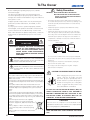
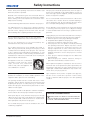
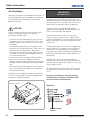
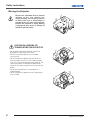
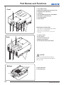
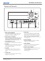

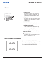
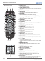
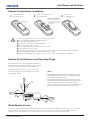
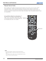
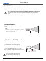
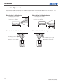
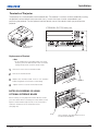

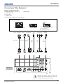
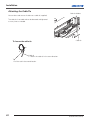
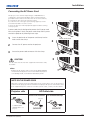
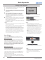

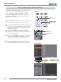
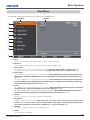
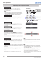


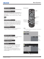
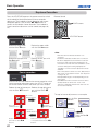
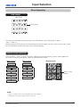

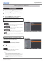
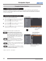
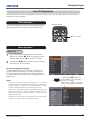
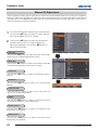
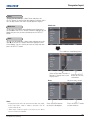
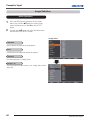
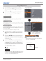

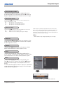
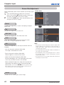
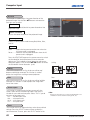
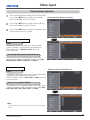
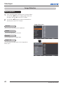
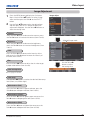
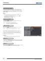
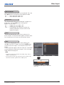

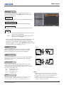
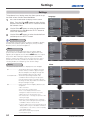
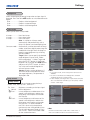
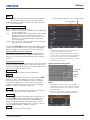
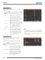
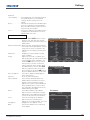
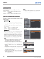
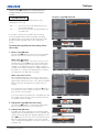


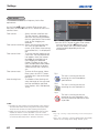
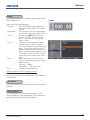
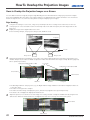
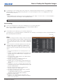
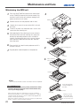
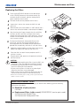
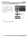
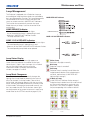

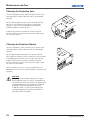
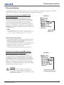
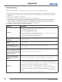
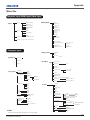
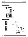
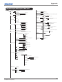
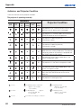
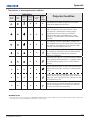
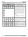
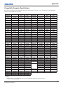
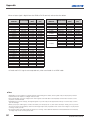
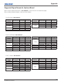
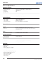
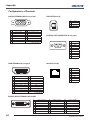
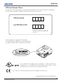
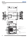
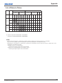


![Network Set-up and Operation [LX505/LX605]](http://vs1.manualzilla.com/store/data/005961160_1-7c70f8cf6199dbe368f392203d85e61b-150x150.png)
![CCM-LX [103-115108-01] QUICK SETUP GUIDE](http://vs1.manualzilla.com/store/data/005977333_1-ac67f3228bf0f13da08c247c088ce509-150x150.png)