1
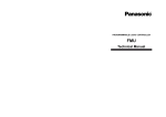
PROGRAMMABLE CONTROLLERS FP7 Digital I/O Units User’s Manual ACGM0704V1EN 09/2014 Before beginning Liability and copyright for the hardware This manual and everything described in it are copyrighted. You may not copy this manual, in whole or part, without written consent of Panasonic Electric Works Europe AG (PEWEU). PEWEU pursues a policy of continuous improvement of the design and performance of its products. Therefore we reserve the right to change the manual/product without notice. In no event will PEWEU be liable for direct, special, incidental, or consequential damage resulting from any defect in the product or its documentation, even if advised of the possibility of such damages. We invite your comments on this manual. Please e-mail us at: [email protected]. Please direct support matters and technical questions to your local Panasonic representative. Limited warranty If physical defects caused by distribution are found, PEWEU will replace/repair the product free of charge. Exceptions include: When physical defects are due to different usage/treatment of the product other than described in the manual. When physical defects are due to defective equipment other than the distributed product. When physical defects are due to modifications/repairs by someone other than PEWEU. 2 When physical defects are due to natural disasters. FP7 Digital I/O Units User's Manual Warnings used in this manual One or more of the following warnings may be used in this documentation: DANGER Indicates a hazardous situation which, if not avoided, will result in death or serious injury. WARNING Indicates a hazardous situation which, if not avoided, could result in serious or moderate injury. CAUTION Indicates a hazardous situation which, if not avoided, could result in minor or moderate injury. NOTICE Indicates a property damage message. FP7 Digital I/O Units User's Manual 3 Scope of this manual This manual covers: unit types parts and functions input and output specifications input time constant setting function wiring instructions Please refer to the FP7 CPU Hardware User's Manual for information on: restrictions on unit combinations I/O allocation methods operating instructions troubleshooting information maintenance instructions error codes unit dimensions Please refer to the FP Series Programming Manual or to the online help of Control FPWIN Pro for information on: system instructions special internal relays data registers system variables memory area tables programming examples For documentation on other units used with the FP7, please refer to the hardware manual for that unit. All manuals can be downloaded from the Panasonic Web site (http://www.panasonic-electric-works.com). 4 FP7 Digital I/O Units User's Manual Safety measures Operating environment After installing the unit, make sure to use it within the range of the general specifications: Ambient temperature: 0°C to +55°C Ambient humidity: 10%–95% RH (at 25°C, non-condensing) Pollution degree: 2 Do not use the unit in the following environments: Direct sunlight Sudden temperature changes causing condensation Inflammable or corrosive gases Excessive airborne dust, metal particles or salts Benzine, paint thinner, alcohol or other organic solvents or strong alkaline solutions such as ammonia or caustic soda Vibration, shock or direct drop of water Influence from power transmission lines, high voltage equipment, power cables, power equipment, radio transmitters, or any other equipment that would generate high switching surges. Maintain at least 100mm of space between these devices and the unit. Static electricity Before touching the unit or equipment, always touch some grounded metal to discharge any static electricity you may have generated (especially in dry locations). The discharge of static electricity can damage parts and equipment. Protection of power supply Use a twisted power supply wire. Isolate the wiring systems to the CPU, input/output devices, and mechanical power apparatus. An insulated power supply with an internal protective circuit should be used (FP power supply). The power supply for the CPU is a non-insulated circuit, so if an incorrect voltage is directly applied, the internal circuit may be damaged or destroyed. FP7 Digital I/O Units User's Manual 5 If using a power supply device without an internal protective circuit, always make sure power is supplied to the unit through a protective element such as a fuse. Be sure to supply power to a CPU and an expansion unit from the same power supply, and turn the power on and off simultaneously for both. Power supply sequence Make sure the power supply of the CPU turns off before the power supply for input and output. If the power supply for input and output is turned off first, the CPU will detect the input fluctuations and may begin an unexpected operation. Before turning on the power When turning on the power for the first time, be sure to take the precautions given below. During installation, check that there are no scraps of wiring, particularly conductive fragments, adhering to the unit. Verify that the power supply wiring, I/O wiring, and power supply voltage are all correct. Sufficiently tighten the installation and terminal screws. Set the operation mode selector to PROG mode. Request concerning program storage To prevent the accidental loss of programs, the user should consider the following measures: Backing up programs: To avoid accidentally losing programs, destroying files, or overwriting the contents of a file, use the backup or export functions of Control FPWIN Pro and store the files in a safe place. Additionally, you can print out the entire project documentation. Specifying passwords: The password setting is designed to avoid programs being accidentally overwritten. If the password is forgotten, however, it will be impossible to overwrite the program even if you want to. Also, if a password is forcibly bypassed, the program is deleted. Therefore, please note the password in a safe location. 6 FP7 Digital I/O Units User's Manual Table of contents Table of contents 1. 2. Overview .................................................................................................................................... 9 1.1 Unit types ......................................................................................................... 9 1.2 Parts and functions ...........................................................................................10 Specifications ......................................................................................................................... 12 2.1 General specifications ........................................................................................12 2.2 Current consumption .........................................................................................13 2.3 Input unit specifications .....................................................................................13 2.3.1 16 inputs (AFP7X16DW) ...........................................................................13 2.3.2 32 inputs (AFP7X32D2) ............................................................................14 2.3.3 64 inputs (AFP7X64D2) ............................................................................16 2.4 Output unit specifications ...................................................................................18 2.4.1 16 relay outputs (AFP7Y16R) ....................................................................18 2.4.2 16 sink (NPN) outputs (AFP7Y16T) ............................................................20 2.4.3 16 source (PNP) outputs (AFP7Y16P) .........................................................21 2.4.4 32 sink (NPN) outputs (AFP7Y32T) ............................................................23 2.4.5 32 source (PNP) outputs (AFP7Y32P) .........................................................25 2.4.6 64 sink (NPN) outputs (AFP7Y64T) ............................................................27 2.4.7 64 source (PNP) outputs (AFP7Y64P) .........................................................29 2.5 Mixed I/O unit specifications...............................................................................33 2.5.1 32 inputs/32 sink (NPN) outputs (AFP7XY64D2T) ........................................33 2.5.2 32 inputs/32 source (PNP) outputs (AFP7XY64D2P) .....................................38 2.6 3. Input time constant setting function ....................................................................43 Wiring ...................................................................................................................................... 44 3.1 Before wiring ....................................................................................................44 3.2 Input wiring .....................................................................................................44 3.2.1 Photoelectric and proximity sensors ...........................................................44 3.2.2 Input wiring precautions ...........................................................................47 3.3 Output wiring ...................................................................................................50 3.3.1 Protective circuit for inductive loads ...........................................................50 3.3.2 Protective circuit for capacitive loads ..........................................................51 3.3.3 Overload protection .................................................................................51 3.3.4 Grounding of AFP7Y16R ............................................................................52 3.4 Wiring the terminal block ...................................................................................53 3.5 Wiring the MIL connector ...................................................................................54 3.5.1 Connectors for wire-pressed terminal cables ...............................................54 FP7 Digital I/O Units User's Manual 7 Table of contents 3.5.2 Flat cable connectors ............................................................................... 57 8 FP7 Digital I/O Units User's Manual Overview Chapter 1 Overview 1.1 Unit types Input unit Type Inputs Connection Description Product no. DC input 16 Terminal block 12–24V DC ±COM terminal Response time configurable AFP7X16DW 32 MIL connector 24V DC ±COM terminal Response time configurable AFP7X32D2 64 MIL connector 24V DC ±COM terminal Response time configurable AFP7X64D2 Output unit Type Outputs Connection Description Product no. Relay 16 Terminal block Load current: 2A/output, 5A/common; 16 outputs/common; without relay socket AFP7Y16R Transistor, sink (NPN) 16 Terminal block Load current: 1A/output, 5A/common; 16 outputs/common AFP7Y16T 32 MIL connector Load current: 0.3A/output, 3.2A/common; 32 outputs/common AFP7Y32T 64 MIL connector Load current: 0.3A (8 outputs, Y0–Y7) and 0.1A (56 outputs, Y8–Y3F), 3.2A/common; 32 outputs/common AFP7Y64T 16 Terminal block Load current: 1A/output, 5A/common; 16 outputs/common AFP7Y16P 32 MIL connector Load current: 0.3A/output, 3.2A/common; 32 outputs/common AFP7Y32P 64 MIL connector Load current: 0.3A (8 outputs, Y0–Y7) and 0.1A (56 outputs, Y8–Y3F); 3.2A/common; 32 outputs/common AFP7Y64P Transistor, source (PNP) FP7 Digital I/O Units User's Manual 9 Overview Mixed I/O unit Type I/Os Connection Description Product no. DC input Transistor output, sink (NPN) Inputs: 32 MIL connector 24V DC ±COM terminal Response time configurable AFP7XY64D2T Outputs: 32 MIL connector Load current: 0.3A (8 outputs, Y0–Y7) and 0.1A (24 outputs: Y8–Y1F); 3.2A/common; 32 outputs/common Inputs: 32 MIL connector 24V DC ±COM terminal Response time configurable Outputs: 32 MIL connector Load current 0.3A (8 outputs: Y0–Y7) and 0.1A (24 outputs: Y8–Y1F); 3.2A/common and 32 outputs/common DC input Transistor output, source (PNP) AFP7XY64D2P 1.2 Parts and functions Terminal block type, 16 inputs MIL connector type, 32 inputs MIL connector type, 64 inputs Q Input status LEDs/Output status LEDs 10 FP7 Digital I/O Units User's Manual Overview Indicate the ON/OFF status of each input and output. W Terminal block release lever By lowering this lever, the terminal block can be removed from the unit without disconnecting the wiring. After installation, push in the lock button at the bottom of the unit to lock in the terminal block. E DIN rail attachment lever Used for easy attachment to a DIN rail. R Expansion connector Used to connect the internal circuits of two or more units. T Terminal block Connect power supplies for the purpose of operating and driving I/O circuits. Y 40-pin MIL connector Connect power supplies for the purpose of operating and driving I/O circuits. Connectors for wire-pressed terminal cables or flat cable connectors can be used. U Input/output LED selector Switches between the first 32 LEDs and the second 32 LEDs of the display for units with 64 I/Os. I Expansion hook Used to fix expansion units. FP7 Digital I/O Units User's Manual 11 Specifications Chapter 2 Specifications 2.1 General specifications Item Description Ambient temperature 0 to +55°C Storage temperature -40 to +70°C Ambient humidity 10%–95% RH (at 25°C, non-condensing) Storage humidity 10%–95% RH (at 25°C, non-condensing) Breakdown voltage (Cutoff current: 5mA) DC input Transistor output Insulation resistance (measured with a 500V DC megger) Vibration resistance – Output terminals Output terminals (of different COM terminals) 500V AC for 1min 2300V AC for 1min Input terminals Power supply terminal/Function earth 500V AC for 1min – Output terminals Power supply terminal/Function earth 500V AC for 1min 2300V AC for 1min Input terminals Output terminals Min. 100 – Output terminals Output terminals (of different COM terminals) Min. 100 Min. 100 Input terminals Power supply terminal/Function earth Min. 100 – Output terminals Power supply terminal/Function earth Min. 100 Min. 100 1) 147m/s2, 3 times on 3 axes (in X, Y, and Z direction) Noise immunity DC input/Transistor output: 1000Vp-p with pulse widths 50ns and 1s (based on in-house measurements) Relay output: 1000Vp-p with pulse widths 50ns and 1s (based on in-house measurements) Operation conditions Free from corrosive gases and excessive dust Conformity to CE Directives EMC: EN 61131-2, LVD: EN 61131-2 Overvoltage category II Pollution degree 2 1) 12 Input terminals Output terminals 500V AC for 1min 5–8.4Hz, amplitude of 3.5mm 8.4–150Hz, constant acceleration of 9.8m/s2, 10min on 3 axes (1 octave/min) 1) Shock resistance Relay output Based on JIS B 3502 and IEC 61131-2 FP7 Digital I/O Units User's Manual Specifications 2.2 Current consumption Type of unit I/Os Internal current Product no. consumption (24V DC) DC input 16 25mA AFP7X16DW 32 30mA AFP7X32D2 64 35mA AFP7X64D2 Relay output 16 180mA AFP7Y16R Transistor output, sink (NPN) 16 35mA AFP7Y16T 32 50mA AFP7Y32T 64 75mA AFP7Y64T 16 35mA AFP7Y16P 32 50mA AFP7Y32P 64 Transistor output, source (PNP) 75mA AFP7Y64P Mixed I/O unit Input: 32 DC input/Transistor output, Output: 32 sink (NPN) 55mA AFP7XY64D2T Mixed I/O unit Input: 32 DC input/Transistor output, Output:32 source (PNP) 55mA AFP7XY64D2P 2.3 Input unit specifications 2.3.1 16 inputs (AFP7X16DW) Item Description Insulation method Optical coupler Rated input voltage 12–24V DC Rated input current 6mA (at 24V DC) Input impedance 3.6k Operating voltage range 10.2–26.4V DC Min. ON voltage/min. ON current 9.6V DC/2mA Max. OFF voltage/max. OFF current 2.5V DC/1mA Response time FALSE TRUE 0.1ms (input time constant configurable) TRUE FALSE 0.2ms (input time constant configurable) Input points per common 8 Input status LEDs 16 (lit in ON state) Connection Terminal block (Terminal screw M3) Weight 125g FP7 Digital I/O Units User's Manual 13 Specifications Internal circuit diagram Q Internal circuit Terminal layout 2.3.2 32 inputs (AFP7X32D2) 14 Item Description Insulation method Optical coupler Rated input voltage 24V DC Rated input current 2.7mA (at 24V DC) Input impedance 8.2k Operating voltage range 20.4–26.4V DC Min. ON voltage/min. ON current 19.2V DC/2.5mA Max. OFF voltage/max. OFF current 5V DC/1.5mA Response time FALSE TRUE 0.2ms (input time constant configurable) TRUE FALSE 0.2ms (input time constant configurable) Input points per common 32 Input status LEDs 32 (lit in ON state) Connection 40-pin MIL connector Weight 95g FP7 Digital I/O Units User's Manual Specifications Internal circuit diagram Q Internal circuit Terminal layout The COM terminals of the input circuits are connected internally. FP7 Digital I/O Units User's Manual 15 Specifications 2.3.3 64 inputs (AFP7X64D2) Item Description Insulation method Optical coupler Rated input voltage 24V DC Rated input current 2.7mA (at 24V DC) Input impedance 8.2k Operating voltage range 20.4–26.4V DC Min. ON voltage/min. ON current 19.2V DC/2.5mA Max. OFF voltage/max. OFF current 5V DC/1.5mA Response time FALSE TRUE 0.2ms (input time constant configurable) TRUE FALSE 0.2ms (input time constant configurable) Input points per common 32 Input status LEDs 32 (lit in ON state) Connection 40-pin MIL connector Weight 110g Inputs that are TRUE simultaneously Keep the number of inputs per common which are simultaneously TRUE within the following range as determined by the ambient temperature. x Ambient temperature y Number of inputs per common that are TRUE simultaneously Q At 26.4V DC W At 24V DC 16 FP7 Digital I/O Units User's Manual Specifications Internal circuit diagram Q Internal circuit Terminal layout The COM terminals of each connector are connected internally. FP7 Digital I/O Units User's Manual 17 Specifications 2.4 Output unit specifications 2.4.1 16 relay outputs (AFP7Y16R) Item Description Insulation method Relay Nominal switching capacity (resistive load) 2A 250V AC, 2A 30V DC (5A/common) Minimum load current 1mA 100mV (resistive load) Response time FALSE TRUE 10ms TRUE FALSE 8ms Mechanical lifetime 20 000 000 operations (switching frequency: 180 operations/min) Electrical lifetime 100 000 operations (switching frequency at nominal switching capacity: 20 operations/min) Surge absorber Snubber circuit (Leakage current: 0.2mA) Relay sockets – Outputs per common 16 Operation indicator 16-point LED indicator (lit in ON state) Connection Terminal block (M3 terminal screws) Weight 180g Internal circuit diagram Q Internal circuit 2 Load In order to avoid the effects of noise, be sure to ground the function earth terminal. 18 FP7 Digital I/O Units User's Manual Specifications Restriction on power supply voltage Refer to the following figure and reduce the supply voltage according to the ambient temperature. x Ambient temperature y Power supply voltage Terminal layout FP7 Digital I/O Units User's Manual 19 Specifications 2.4.2 16 sink (NPN) outputs (AFP7Y16T) Item Description Insulation method Optical coupler Output type Open collector Rated load voltage 5–24V DC Operating load voltage range 4.75–26.4V DC Max. load current 1A/output (max. 5A/common) Max. inrush current 3A OFF state leakage current 1A ON state voltage drop 0.5V Response time External power supply FALSE TRUE 0.05ms (load current: 0.5mA) TRUE FALSE 0.3ms (load current: 0.5mA) Voltage 4.75–26.4V DC Current 70mA (at 24V DC) Surge absorber Zener diode Short circuit protection – Outputs per common 16 Operation indicator 16-point LED indicator (lit in ON state) Connection Terminal block (M3 terminal screws) Weight 125g Internal circuit diagram Q Internal circuit 2 Load 20 FP7 Digital I/O Units User's Manual Specifications Terminal layout 2.4.3 16 source (PNP) outputs (AFP7Y16P) Item Description Insulation method Optical coupler Output type Open collector Rated load voltage 5–24V DC Operating load voltage range 4.75–26.4V DC Max. load current 1A/output (max. 5A/common) Max. inrush current 3A OFF state leakage current 1A ON state voltage drop 0.5V Response time External power supply FALSE TRUE 0.05ms (load current: 0.5mA) TRUE FALSE 0.3ms (load current: 0.5mA) Voltage 4.75–26.4V DC Current 70mA (at 24V DC) Surge absorber Zener diode Short circuit protection – Outputs per common 16 Operation indicator 16-point LED indicator (lit in ON state) Connection Terminal block (M3 terminal screws) Weight 125g FP7 Digital I/O Units User's Manual 21 Specifications Internal circuit diagram Q Internal circuit 2 Load Terminal layout 22 FP7 Digital I/O Units User's Manual Specifications 2.4.4 32 sink (NPN) outputs (AFP7Y32T) Item Description Insulation method Optical coupler Output type Open collector Rated load voltage 5–24V DC Operating load voltage range 4.75–26.4V DC Max. load current 0.3A/output (20.4–26.4V DC) and 30mA/output (4.75V DC) (max. 3.2A/common) Max. inrush current 0.6A OFF state leakage current 1A ON state voltage drop 0.5V Response time FALSE TRUE 0.1ms (load current: 1mA) TRUE FALSE 0.3ms (load current: 1mA) External power supply Voltage 4.75–26.4V DC Current 110mA (at 24V DC) Surge absorber Zener diode Short circuit protection – Outputs per common 32 Operation indicator 32-point LED indicator (lit in ON state) Connection 40-pin MIL connector Weight 95g Internal circuit diagram Q Internal circuit 2 Load FP7 Digital I/O Units User's Manual 23 Specifications Restrictions on load current Refer to the following figure and reduce the load current according to the external power supply voltage. x External power supply voltage y Max. load current Terminal layout Although the positive and negative terminals are connected internally, connect these terminals externally as well. 24 FP7 Digital I/O Units User's Manual Specifications 2.4.5 32 source (PNP) outputs (AFP7Y32P) Item Description Insulation method Optical coupler Output type Open collector Rated load voltage 5–24V DC Operating load voltage range 4.75–26.4V DC Max. load current 0.3A/output (20.4–26.4V DC) and 30mA/output (4.75V DC) (max. 3.2A/common) Max. inrush current 0.6A OFF state leakage current 1A ON state voltage drop 0.5V Response time FALSE TRUE 0.1ms (load current: 2mA) TRUE FALSE 0.5ms (load current: 2mA) Voltage 4.75–26.4V DC Current 130mA (at 24V DC) External power supply Surge absorber Zener diode Short circuit protection – Outputs per common 32 Operation indicator 32-point LED indicator (lit in ON state) Connection 40-pin MIL connector Weight 95g Internal circuit diagram Q Internal circuit 2 Load FP7 Digital I/O Units User's Manual 25 Specifications Restrictions on load current Refer to the following figure and reduce the load current according to the external power supply voltage. x External power supply voltage y Max. load current Terminal layout Although the positive and negative terminals are connected internally, connect these terminals externally as well. 26 FP7 Digital I/O Units User's Manual Specifications 2.4.6 64 sink (NPN) outputs (AFP7Y64T) Item Description Insulation method Optical coupler Output type Open collector Rated load voltage 5–24V DC Operating load voltage range 4.75–26.4V DC Max. load current Y0–Y7 0.3A/output (20.4–26.4V DC) and 30mA/output (4.75V DC) (max. 3.2A/common) Any other output 0.1A/output (20.4–26.4V DC) and 15mA/output (4.75V DC) (max. 3.2A/common) Max. inrush current 0.6A OFF state leakage current 1A ON state voltage drop 0.5V Response time FALSE TRUE 0.1ms (load current: 2mA) TRUE FALSE 0.3ms (load current: 2mA) External power supply Voltage 4.75–26.4V DC Current 70mA/common (at 24V DC) Surge absorber Zener diode Short circuit protection – Outputs per common 32 Operation indicator 32-point LED indicator (lit in ON state) Connection 40-pin MIL connector x2 Weight 115g Internal circuit diagram Q Internal circuit 2 Load FP7 Digital I/O Units User's Manual 27 Specifications Restrictions on load current Refer to the following figure and reduce the load current according to the external power supply voltage. Y0–Y7, 0.3A/output: x External power supply voltage y Max. load current Any other output, 0.1A/output: x External power supply voltage y Max. load current 28 FP7 Digital I/O Units User's Manual Specifications Terminal layout Although the positive and negative terminals are connected internally, connect these terminals externally as well. 2.4.7 64 source (PNP) outputs (AFP7Y64P) Item Description Insulation method Optical coupler Output type Open collector Rated load voltage 5–24V DC Operating load voltage range 4.75–26.4V DC Max. load current Y0–Y7 0.3A/output (20.4–26.4V DC) and 30mA/output (4.75V DC) (max. 3.2A/common) Any other output 0.1A/output (20.4–26.4V DC) and 15mA/output (4.75V DC) (max. 3.2A/common) Max. inrush current 0.6A OFF state leakage current 1A ON state voltage drop 0.5V Response time FALSE TRUE 0.1ms (load current: 2mA) TRUE FALSE 0.5ms (load current: 2mA) Voltage 4.75–26.4V DC Current 90mA/common (at 24V DC) External power supply Surge absorber Zener diode Short circuit protection – Outputs per common 32 FP7 Digital I/O Units User's Manual 29 Specifications Item Description Operation indicator 32-point LED indicator (lit in ON state) Connection 40-pin MIL connector x2 Weight 115g Outputs that are TRUE simultaneously Keep the number of outputs per common which are simultaneously TRUE within the following range as determined by the ambient temperature. x Ambient temperature y Number of outputs per common that are TRUE simultaneously Q At 24V DC W At 26.4V DC Internal circuit diagram Q Internal circuit 2 Load Restrictions on load current Refer to the following figure and reduce the load current according to the external power supply voltage. 30 FP7 Digital I/O Units User's Manual Specifications Y0–Y7, 0.3A/output: x External power supply voltage y Max. load current Any other output, 0.1A/output: x External power supply voltage y Max. load current FP7 Digital I/O Units User's Manual 31 Specifications Terminal layout Although the positive and negative terminals are connected internally, connect these terminals externally as well. 32 FP7 Digital I/O Units User's Manual Specifications 2.5 Mixed I/O unit specifications 2.5.1 32 inputs/32 sink (NPN) outputs (AFP7XY64D2T) Input Item Description Insulation method Optical coupler Rated input voltage 24V DC Rated input current 2.7mA (at 24V DC) Input impedance 8.2k Operating voltage range 20.4–26.4V DC Min. ON voltage/min. ON current 19.2V DC/2.5mA Output Max. OFF voltage/max. OFF current 5V DC/1.5mA Response time FALSE TRUE 0.2ms (input time constant configurable) TRUE FALSE 0.2ms (input time constant configurable) Input points per common 32 Insulation method Optical coupler Output type Open collector Rated load voltage 5–24V DC Operating load voltage range 4.75–26.4V DC Max. load current Y0–Y7 0.3A/output (20.4–26.4V DC) and 30mA/output (4.75V DC) (max. 3.2A/common) Any other output 0.1A/output (20.4–26.4V DC) and 15mA/output (4.75V DC) (max. 3.2A/common) Max. inrush current 0.6A OFF state leakage current 1A ON state voltage drop 0.5V Response time FALSE TRUE 0.1ms (load current: 2mA) TRUE FALSE 0.3ms (load current: 2mA) External power Voltage supply Current 4.75–26.4V DC Surge absorber Zener diode Short circuit protection – Outputs per common 32 70mA/common (at 24V DC) Operation indicator 32-point LED indicator (lit in ON state) Connection 40-pin MIL connector x2 Weight 115g FP7 Digital I/O Units User's Manual 33 Specifications Inputs/outputs that are TRUE simultaneously Keep the number of inputs/outputs per common which are simultaneously TRUE within the following range as determined by the ambient temperature. x Ambient temperature y Number of inputs/outputs per common that are TRUE simultaneously Q At 24V DC W At 26.4V DC Internal circuit diagram Input: Q Internal circuit 34 FP7 Digital I/O Units User's Manual Specifications Output: Q Internal circuit 2 Load Restrictions on load current Refer to the following figure and reduce the load current according to the external power supply voltage. Y0–Y7, 0.3A/output: x External power supply voltage y Max. load current FP7 Digital I/O Units User's Manual 35 Specifications Any other output, 0.1A/output: x External power supply voltage y Max. load current Terminal layout Input: The COM terminals of the input circuits are connected internally. 36 FP7 Digital I/O Units User's Manual Specifications Output: Although the positive and negative terminals are connected internally, connect these terminals externally as well. FP7 Digital I/O Units User's Manual 37 Specifications 2.5.2 32 inputs/32 source (PNP) outputs (AFP7XY64D2P) Input Item Description Insulation method Optical coupler Rated input voltage 24V DC Rated input current 3.4A (at 24V DC) Input impedance 7.5k Operating voltage range 20.4–26.4V DC Min. ON voltage/min. ON current 19.2V DC/2.5mA Output 38 Max. OFF voltage/max. OFF current 5V DC/1.5mA Response time FALSE TRUE 0.2ms (input time constant configurable) TRUE FALSE 0.2ms (input time constant configurable) Input points per common 32 Insulation method Optical coupler Output type Open collector Rated load voltage 5–24V DC Operating load voltage range 4.75–26.4V DC Max. load current Y0–Y7 0.3A/output (20.4–26.4V DC) and 30mA/output (4.75V DC) (max. 3.2A/common) Any other output 0.1A/output (20.4–26.4V DC) and 15mA/output (4.75V DC) (max. 3.2A/common) Max. inrush current 0.6A OFF state leakage current 1A ON state voltage drop 0.5V Response time FALSE TRUE 0.1ms (load current: 2mA) TRUE FALSE 0.5ms (load current: 2mA) External power Voltage supply Current 4.75–26.4V DC Surge absorber Zener diode Short circuit protection – Outputs per common 32 90mA/common (at 24V DC) Operation indicator 32-point LED indicator (lit in ON state) Connection 40-pin MIL connector x2 Weight 115g FP7 Digital I/O Units User's Manual Specifications Inputs/outputs that are TRUE simultaneously Keep the number of inputs/outputs per common which are simultaneously TRUE within the following range as determined by the ambient temperature. x Ambient temperature y Number of inputs/outputs per common that are TRUE simultaneously Q At 26.4V DC W At 24V DC Internal circuit diagram Input: Q Internal circuit FP7 Digital I/O Units User's Manual 39 Specifications Output: Q Internal circuit 2 Load Restrictions on load current Refer to the following figure and reduce the load current according to the external power supply voltage. Y0–Y7, 0.3A/output: x External power supply voltage y Max. load current 40 FP7 Digital I/O Units User's Manual Specifications Any other output, 0.1A/output: x External power supply voltage y Max. load current Terminal layout Input: The COM terminals of the input circuits are connected internally. FP7 Digital I/O Units User's Manual 41 Specifications Output: Although the positive and negative terminals are connected internally, connect these terminals externally as well. 42 FP7 Digital I/O Units User's Manual Specifications 2.6 Input time constant setting function Input time constants for input units or mixed I/O units can be changed as necessary. The selected time constant is added to the hardware-specific response time of the unit. Procedure 1. Double-click "PLC" in the navigator 2. Double-click "I/O map and unit configuration" 3. Double-click the desired unit type 4. Select a value from the "Input time constant" list box 5. [OK] Exam ple DC input unit with 16 inputs Hardware-specific response time Selected input time constant Resulting response time FALSE TRUE 0.1ms 1.0ms 1.1ms TRUE FALSE 0.2ms 1.2ms Error margin The input time constant has an error margin, which should be kept in mind when selecting a set value. The accuracy of each time constant is shown in the table below. Set value Time constant Min. Max. No setting – – 0.1ms 0.1ms 0.2ms 0.5ms 0.3ms 0.7ms 1ms 0.7ms 1.3ms 5ms 3.0ms 5.2ms 10ms 6.0ms 10.4ms 20ms 12.1ms 20.7ms 70ms 48.6ms 82.8ms FP7 Digital I/O Units User's Manual 43 Wiring Chapter 3 Wiring 3.1 Before wiring Before the wiring, carefully confirm the specifications for the units to be wired. Specifically, limitations on the ambient temperature, the number of I/Os that can be TRUE simultaneously, and the supply voltage will differ for different units. 3.2 Input wiring For connecting input devices see the diagrams and recommendations given below. 3.2.1 Photoelectric and proximity sensors Relay output type NPN input: Sensor FP7 Q Internal circuit W Relay E Power supply for sensor R Power supply for input T Input terminal 44 FP7 Digital I/O Units User's Manual Wiring PNP input: Sensor FP7 Q Internal circuit W Relay E Power supply for sensor R Power supply for input T Input terminal Open collector output type NPN output: Sensor FP7 Q Internal circuit W Output E Power supply for input R Input terminal FP7 Digital I/O Units User's Manual 45 Wiring PNP output: Sensor FP7 Q Internal circuit W Output E Power supply for input R Input terminal Voltage output (universal output) type Sensor FP7 Q Internal circuit W Output E Power supply for input R Input terminal 46 FP7 Digital I/O Units User's Manual Wiring Two-wire output type Sensor FP7 Q Internal circuit W Output E Power supply for input R Input terminal 3.2.2 Input wiring precautions When using an LED-equipped Reed switch When an LED is connected in series to an input contact such as an LED-equipped Reed switch, make sure that the voltage applied to the PLC input terminal is greater than the ON voltage. In particular, take care when connecting a number of switches in series. LED-equipped Reed switch FP7 Q LED W Contact E ON voltage R Input terminal FP7 Digital I/O Units User's Manual 47 Wiring When using a two-wire type sensor If the input of the PLC does not turn off because of leakage current from the two-wire type sensor (photoelectric sensor or proximity sensor), the use of a bleeder resistor is recommended, as shown below. Two-wire type sensor FP7 Q Internal circuit W Bleeder resistor E Input terminal Using an input unit with 16 inputs (AFP7X16DW): The OFF voltage of the input is 2.5V. Therefore, select a bleeder resistor value R so that the voltage between the COM terminal and the input terminal will be less than 2.5V. The input impedance is 3.6k. Therefore: The wattage W of the resistor is: V = Power supply voltage In the actual selection, use a value that is 3 to 5 times the value of W. 48 FP7 Digital I/O Units User's Manual Wiring When using an LED-equipped limit switch If the input of the PLC does not turn off because of the leakage current from the LED-equipped limit switch, the use of a bleeder resistor is recommended, as shown below. LED-equipped limit switch FP7 r Internal resistor of limit switch (k) R Bleeder resistor (k) Q Internal circuit W Power supply for input E Input terminal Using an input unit with 16 inputs (AFP7X16DW): The OFF voltage of the input is 2.5V. Therefore, when the power supply is 24V, select the bleeder resistor R so that the current will be greater than the result of this formula: The input impedance is 3.6k. The resistance R of the bleeder resistor is: The wattage W of the resistor is: V = Power supply voltage In the actual selection, use a value that is 3 to 5 times the value of W. FP7 Digital I/O Units User's Manual 49 Wiring 3.3 Output wiring 3.3.1 Protective circuit for inductive loads With an inductive load, a protective circuit should be installed in parallel with the load. When switching DC inductive loads with the relay output type, be sure to connect a diode across the ends of the load. Using an AC inductive load (relay output type) FP7 Q Output terminal W Load E Surge absorber, e.g. resistance R: 50, capacitance C: 0.47F FP7 Q Output terminal W Load E Varistor Using a DC inductive load FP7 50 Q Output terminal W Load E Diode FP7 Digital I/O Units User's Manual Wiring 3.3.2 Protective circuit for capacitive loads When connecting loads with large inrush currents, connect a protection circuit as shown below to minimize their effect. FP7 Q Output terminal W Load E Resistor FP7 Q Output terminal W Load E Inductor 3.3.3 Overload protection There is no fuse in the output circuit. It is recommended to install external fuses in every circuit to reduce the risk of burning out the output circuit when the output is shorted. There are times that the elements for the output units cannot be protected even if external fuses are connected. FP7 Digital I/O Units User's Manual 51 Wiring 3.3.4 Grounding of AFP7Y16R If necessary, ground the instrument to increase the noise resistance. Be sure to ground the relay output unit AFP7Y16R (see p. 18) to avoid the effects of noise. The grounding connection should have a resistance of 100 or less. The point of grounding should be as close to the PLC as possible. The ground wire should be as short as possible. Always use an exclusive ground for PLCs and other devices. If two devices share a single ground point, it may produce an adverse effect. Q PLC W Other device (inverter etc.) 52 FP7 Digital I/O Units User's Manual Wiring 3.4 Wiring the terminal block Suitable wire 2 Size Cross-sectional area [mm ] Tightening torque [Nm] AWG22–14 0.3–2.0 0.5–0.6 Wiring method Remove the terminal block to facilitate wiring. Procedure 1. Push down release lever 2. Pull off terminal block Q Terminal block release lever W Bottom of unit E Lock button Note To reattach the terminal block, insert it all the way to its original position and press the lock button on the bottom of the unit. Then confirm that the terminal block is securely attached and cannot be removed. FP7 Digital I/O Units User's Manual 53 Wiring 3.5 Wiring the MIL connector 3.5.1 Connectors for wire-pressed terminal cables This connector is provided with the unit. It allows loose wires to be connected without removing the wire’s insulation. A dedicated pressure connection tool is required. Connector for wire pressed terminal cables (40 pins) Suitable wire (strand wire) Size 2 Cross-sectional area [mm ] Insulation thickness [mm] Rated current AWG22 0.3 1.5–1.1 3A AWG24 0.2 Connector sets provided with the unit Manufacturer Product name Unit type and required quantity 32-point-type unit 64-point-type unit/ Mixed I/O unit Panasonic Note Housing (40 pins) 11 set 12 sets Semi-cover (40 pins) 21 set 22 sets Contact (for AWG22 or 24) 5 pins 81 set 82 sets Units with 32 I/Os are provided with one set, units with 64 I/Os and mixed I/O units are provided with two sets each. If you need more connectors, purchase AFP2801 (2 sets/pack). Pressure connection tool (AXY52000FP) 54 FP7 Digital I/O Units User's Manual Wiring Wiring method The wire end can be directly crimped without removing the wire's insulation, saving labor. Procedure 1. Bend the contact back from the carrier and set it in the pressure connection tool 2. Insert wire without removing its insulation until it stops 3. Lightly grip tool 4. Insert press-fitted wire into connector housing FP7 Digital I/O Units User's Manual 55 Wiring 5. When all wires have been inserted, fit semi-cover into place Note If there is a wiring mistake or the cable is incorrectly pressure-connected, the contact puller pin provided with the fitting can be used to remove the contact. Q Press the housing against the pressure connection tool so that the contact puller pin comes in contact with this section. 56 FP7 Digital I/O Units User's Manual Wiring 3.5.2 Flat cable connectors The relationship between the cable number of flat cable connectors and I/O addresses is shown below. Connection diagram for units with 64 inputs or outputs and for mixed I/O units Q Cable no. 1 Connector 1 (CN1) Cable no. Input no. Output no. Cable no. Input no. Output no. 1 X0 Y0 21 X10 Y10 2 X8 Y8 22 X18 Y18 3 X1 Y1 23 X11 Y11 4 X9 Y9 24 X19 Y19 5 X2 Y2 25 X12 Y12 6 XA Y6 26 X1A Y1A 7 X3 Y3 27 X13 Y13 8 XB YB 28 X1B Y1B 9 X4 Y4 29 X14 Y14 10 XC YC 30 X1C Y1C 11 X5 Y5 31 X15 Y15 12 XD YD 32 X1D Y1D 13 X6 Y6 33 X16 Y16 14 XE YE 34 X1E Y1E 15 X7 Y7 35 X17 Y17 16 XF YF 36 X1F Y1F 17 COM 37 COM 18 COM 38 COM 19 NC 39 NC 20 NC 40 NC FP7 Digital I/O Units User's Manual 57 Wiring Connector 2 (CN2) Cable no. Input no. Output no. Cable no. Input no. Output no. 1 X20 Y20 21 X30 Y30 2 X28 Y28 22 X38 Y38 3 X21 Y21 23 X31 Y31 4 X29 Y29 24 X39 Y39 5 X22 Y22 25 X32 Y32 6 X2A Y26 26 X3A Y3A 7 X23 Y23 27 X33 Y33 8 X2B Y2B 28 X3B Y3B 9 X24 Y24 29 X34 Y34 10 X2C Y2C 30 X3C Y3C 11 X25 Y25 31 X35 Y35 12 X2D Y2D 32 X3D Y3D 13 X26 Y26 33 X36 Y36 14 X2E Y2E 34 X3E Y3E 15 X27 Y27 35 X37 X37 16 X2F Y2F 36 X3F Y3F 17 COM 37 COM 18 COM 38 COM 19 NC 39 NC 20 NC 40 NC Suitable wire (strand wire) 58 Size Pitch Rated current AWG28 (7 wires/ 0.127) 1.27mm 1A FP7 Digital I/O Units User's Manual Record of changes Manual no. Date Description of changes ACGM0704V1EN September 2014 First edition Global Network North America Europe Asia Pacific China Japan Panasonic Electric Works Please contact our Global Sales Companies in: Europe ▸ Headquarters ▸ Austria Panasonic Electric Works Europe AG Panasonic Electric Works Austria GmbH ▸ Benelux Panasonic Industrial Devices Materials Europe GmbH Panasonic Electric Works Sales Western Europe B.V. Panasonic Electric Works Europe AG ▸ Czech Republic ▸ France ▸ Germany ▸ Hungary Panasonic Electric Works Sales Western Europe B.V. Panasonic Electric Works Europe AG Panasonic Electric Works Europe AG ▸ Ireland ▸ Italy Panasonic Electric Works UK Ltd. Panasonic Electric Works Italia srl ▸ Nordic Countries Panasonic Electric Works Europe AG Panasonic Eco Solutions Nordic AB Panasonic Electric Works Polska sp. z o.o ▸ Poland Panasonic Electric Works España S.A. ▸ Spain Panasonic Electric Works Schweiz AG ▸ Switzerland ▸ United Kingdom Panasonic Electric Works UK Ltd. Rudolf-Diesel-Ring 2, 83607 Holzkirchen, Tel. +49 (0) 8024 648-0, Fax +49 (0) 8024 648-111, www.panasonic-electric-works.com Josef Madersperger Str. 2, 2362 Biedermannsdorf, Tel. +43 (0) 2236-26846, Fax +43 (0) 2236-46133 www.panasonic-electric-works.at Ennshafenstraße 30, 4470 Enns, Tel. +43 (0) 7223 883, Fax +43 (0) 7223 88333, www.panasonic-electronic-materials.com De Rijn 4, (Postbus 211), 5684 PJ Best, (5680 AE Best), Netherlands, Tel. +31 (0) 499 372727, Fax +31 (0) 499 372185, www.panasonic-electric-works.nl Administrative centre PLATINIUM, Veveří 3163/111, 616 00 Brno, Tel. +420 541 217 001, Fax +420 541 217 101, www.panasonic-electric-works.cz Succursale française, 10, rue des petits ruisseaux, 91370 Verrières Le Buisson, Tél. +33 (0) 1 6013 5757, Fax +33 (0) 1 6013 5758, www.panasonic-electric-works.fr Rudolf-Diesel-Ring 2, 83607 Holzkirchen, Tel. +49 (0) 8024 648-0, Fax +49 (0) 8024 648-111, www.panasonic-electric-works.de Magyarországi Közvetlen Kereskedelmi Képviselet, 1117 Budapest, Neumann János u. 1., Tel. +36 1 999 89 26 www.panasonic-electric-works.hu Irish Branch Office, Dublin, Tel. +353 (0) 14600969, Fax +353 (0) 14601131, www.panasonic-electric-works.co.uk Via del Commercio 3-5 (Z.I. Ferlina), 37012 Bussolengo (VR), Tel. +39 0456752711, Fax +39 0456700444, www.panasonic-electric-works.it Filial Nordic, Knarrarnäsgatan 15, 164 40 Kista, Sweden, Tel. +46 859476680, Fax +46 859476690, www.panasonic-electric-works.se Jungmansgatan 12, 21119 Malmö, Tel. +46 40 697 7000, Fax +46 40 697 7099, www.panasonic-fire-security.com ul. Wołoska 9A, 02-583 Warszawa, Tel. +48 22 338-11-33, Fax +48 22 338-12-00, www.panasonic-electric-works.pl Barajas Park, San Severo 20, 28042 Madrid, Tel. +34 913293875, Fax +34 913292976, www.panasonic-electric-works.es Grundstrasse 8, 6343 Rotkreuz, Tel. +41 (0) 41 7997050, Fax +41 (0) 41 7997055, www.panasonic-electric-works.ch Sunrise Parkway, Linford Wood, Milton Keynes, MK14 6 LF, Tel. +44 (0) 1908 231555, Fax +44 (0) 1908 231599, www.panasonic-electric-works.co.uk North & South America ▸ USA Panasonic Industrial Devices Sales Company of America 629 Central Avenue, New Providence, N.J. 07974, Tel. 1-908-464-3550, Fax 1-908-464-8513, www.pewa.panasonic.com Asia Pacific / China / Japan ▸ China Panasonic Electric Works Sales (China) Co. Ltd. ▸ Hong Kong Panasonic Industrial Devices Automation Controls Sales (Hong Kong) Co., Ltd. Panasonic Corporation Panasonic Industrial Devices Automation Controls Sales Asia Pacific ▸ Japan ▸ Singapore Level 2, Tower W3, The Towers Oriental Plaza, No. 2, East Chang An Ave., Dong Cheng District, Beijing 100738, Tel. +86-10-5925-5988, Fax +86-10-5925-5973 RM1205-9, 12/F, Tower 2, The Gateway, 25 Canton Road, Tsimshatsui, Kowloon, Hong Kong, Tel. +852-2956-3118, Fax +852-2956-0398 1048 Kadoma, Kadoma-shi, Osaka 571-8686, Japan, Tel. +81-6-6908-1050, Fax +81-6-6908-5781, www.panasonic.net 300 Beach Road, #16-01 The Concourse, Singapore 199555, Tel. +65-6390-3811, Fax +65-6390-3810 ACGM0704V1EN 09/2014