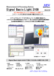
1
Getting Started with
EnSight 8.2
Computational Engineering International, Inc.
2166 N. Salem Street, Suite 101, Apex, NC 27523
USA • 919-363-0883 • 919-363-0833 FAX
http://www.ceintl.com or http://www.ensight.com
Copyright © 1994 - 2006, Computational Engineering International, Inc. All rights reserved.
Printed in the United States of America.
EN-GS Revision History
EN-GS:6.0-1
EN-GS:6.0-2
EN-GS:6.0-3
EN-GS:6.0-4
EN-GS:6.1-1
EN-GS:6.2-1
EN-GS:6.2-2
EN-GS:7.0-1
EN-GS:7.1-1
EN-GS:7.3-1
EN-GS:7.4-1
EN-GS:7.4-2
EN-GS:7.6-1
EN-GS:8.0-1
EN-GS:8.2-1
June 1997
August 1997
October 1997
October 1997
March 1998
September 1998
December 1998
December 1999
April 2000
March 2001
March 2002
October 2002
May 2003
December 2004
August 2006
This document has been reviewed and approved in accordance with Computational Engineering International,
Inc. Documentation Review and Approval Procedures.
This document should be used only for Version 8.2 and greater of the EnSight program.
Information in this document is subject to change without notice. This document contains proprietary
information of Computational Engineering International, Inc. The contents of this document may not be
disclosed to third parties, copied, or duplicated in any form, in whole or in part, unless permitted by contract or
by written permission of Computational Engineering International, Inc. Computational Engineering
International, Inc. does not warranty the content or accuracy of any foreign translations of this document not
made by itself. The Computational Engineering International, Inc. Software License Agreement and Contract
for Support and Maintenance Service supersede and take precedence over any information in this document.
EnSight® is a registered trademark of Computational Engineering International, Inc. All registered trademarks
used in this document remain the property of their respective owners.
CEI’s World Wide Web addresses:
http://www.ceintl.com
or
http://www.ensight.com
Restricted Rights Legend
Use, duplication, or disclosure of the technical data contained in this document by the Government is subject to
restrictions as set forth in subparagraph (c)(1)(ii) of the Rights in Technical Data and Computer Software clause
at DFARS 252.227-7013. Unpublished rights reserved under the Copyright Laws of the United States.
Contractor/Manufacturer is Computational Engineering International, Inc., 2166 N. Salem Street, Suite 101,
Apex, NC 27523.
Table of Contents
Table of Contents
Introduction
1 EnSight Graphical User Interface
1.1 Tour of the GUI. . . . . . . . . . . . . . . . . . . . . . . . . . . . . . . . . . . . . . . . . . . 1-2
1.2 User Interface Conventions . . . . . . . . . . . . . . . . . . . . . . . . . . . . . . . . . 1-8
1.3 Where’s the Rest? . . . . . . . . . . . . . . . . . . . . . . . . . . . . . . . . . . . . . . . 1-13
2 Starting EnSight
Necessary Prerequisites . . . . . . . . . . . . . . . . . . . . . . . . . . . . . . . . . . . . . . . . . . . . . . 2-1
Starting EnSight for Stand-alone Use . . . . . . . . . . . . . . . . . . . . . . . . . . . . . . . . . . . . 2-1
Starting EnSight for Distributed Use - Manual Connection . . . . . . . . . . . . . . . . . . . . 2-2
Starting EnSight for Distributed Use - Automatic Connection . . . . . . . . . . . . . . . . . . 2-2
3 Simple Demonstration
3.1 Reading a Dataset . . . . . . . . . . . . . . . . . . . . . . . . . . . . . . . . . . . . . . . . 3-2
Getting Your Data Into EnSight. . . . . . . . . . . . . . . . . . . . . . . . . . . . . . . . . . . . . . . . . 3-3
3.2 Performing Transformations. . . . . . . . . . . . . . . . . . . . . . . . . . . . . . . . . 3-4
3.3 Parts and Part Attributes . . . . . . . . . . . . . . . . . . . . . . . . . . . . . . . . . . . 3-6
3.4 Saving Files . . . . . . . . . . . . . . . . . . . . . . . . . . . . . . . . . . . . . . . . . . . . 3-11
Saving Images . . . . . . . . . . . . . . . . . . . . . . . . . . . . . . . . . . . . . . . . . . . . . . . . . . . . 3-11
3.5 Using Online Help . . . . . . . . . . . . . . . . . . . . . . . . . . . . . . . . . . . . . . . 3-12
3.6 Exiting EnSight . . . . . . . . . . . . . . . . . . . . . . . . . . . . . . . . . . . . . . . . . . 3-14
3.7 Where’s the Rest? . . . . . . . . . . . . . . . . . . . . . . . . . . . . . . . . . . . . . . . 3-15
4 Flow Visualization Example: Unstructured Mesh
4.1 Reading a Dataset . . . . . . . . . . . . . . . . . . . . . . . . . . . . . . . . . . . . . . . . 4-2
4.2 Feature Demonstration. . . . . . . . . . . . . . . . . . . . . . . . . . . . . . . . . . . . . 4-4
4.3 Where’s the Rest? . . . . . . . . . . . . . . . . . . . . . . . . . . . . . . . . . . . . . . . 4-14
Getting Started with EnSight 8.2
iii
Table of Contents
5 Flow Visualization Example: Structured Mesh
5.1 Reading a Dataset . . . . . . . . . . . . . . . . . . . . . . . . . . . . . . . . . . . . . . . . 5-2
5.2 Feature Demonstration. . . . . . . . . . . . . . . . . . . . . . . . . . . . . . . . . . . . . 5-5
Saving an Archive . . . . . . . . . . . . . . . . . . . . . . . . . . . . . . . . . . . . . . . . . . . . . . . . . 5-10
5.3 Where’s the Rest? . . . . . . . . . . . . . . . . . . . . . . . . . . . . . . . . . . . . . . . 5-11
6 Structural Mechanics Example
6.1 Reading a Dataset . . . . . . . . . . . . . . . . . . . . . . . . . . . . . . . . . . . . . . . . 6-2
6.2 Feature Demonstration. . . . . . . . . . . . . . . . . . . . . . . . . . . . . . . . . . . . . 6-3
6.3 Annotation . . . . . . . . . . . . . . . . . . . . . . . . . . . . . . . . . . . . . . . . . . . . . . 6-8
6.4 Flipbook Animation . . . . . . . . . . . . . . . . . . . . . . . . . . . . . . . . . . . . . . . 6-12
6.5 Where’s the Rest? . . . . . . . . . . . . . . . . . . . . . . . . . . . . . . . . . . . . . . . 6-13
7 Where Do I Go From Here?
Index
iv
Getting Started with EnSight 8.2
Introduction
What’s in Getting Started?
This Getting Started manual contains the following information:
•
An introduction to the EnSight user interface (Chapter 1).
•
How to Start EnSight, stand-alone or distributed (Chapter 2).
•
Some simple, step-by-step demonstrations of basic EnSight functionality (Chapters
3–6).
Conventions Used in Getting Started
The following typographic conventions are used in the Getting Started manual:
A numbered step tells you exactly what to do:
1. Change the value to “0.0” and press Enter.
UNIX and DOS level commands are denoted in a fixed-width font. Never type the
leading “%” – it indicates that the command is to be issued at a shell prompt.
% ensight8.client -cm
Menu selections use “>” to indicate the selection hierarchy. For example, “Tools >
Plane > Line” means to select Plane from the Tools menu and then select Line from the
Plane cascade menu.
Notes and warnings provide particularly important information:
Note: Text emphasized in this fashion is a note.
Warning: Text emphasized in this fashion is a warning. Warnings typically indicate
that your actions may have unintended consequences.
Getting Started with EnSight 8.2
v
Where’s the Rest?
The remainder of the EnSight documentation (as well as a version of this manual) is
available online (and is accessible via the Help menu).
The other documentation is divided into four manuals:
How To
The How To documentation consists of relatively short articles that describe how to
perform a specific operation in EnSight, such as change the color of an object or create
an isosurface. Step-by-step instructions and pictures of relevant dialogs are included.
In addition, each How To article typically contains numerous hyperlinks (colored blue)
to other related articles (and relevant sections of the User Manual).
To access a list of the online How To articles, select Help > How To Manual.... From
this location you can easily navigate to any of the articles or to a comprehensive index.
User Manual
The User Manual provides a detailed reference for EnSight.
To access the User Manual, select Help > User Manual.... From this location you can
easily navigate to any of the chapters, the table of contents, or a comprehensive index.
Note: When navigating in the online User Manual, you can easily return to the User
Manual Table Title Page by clicking on the footer text: EnSight 8 User Manual.
Command
Language Manual
The Command Language Manual provides details for each command of the command
language used in EnSight. Note that this is an advanced manual which is generally not
needed by most users.
To access the Command Language Manual, select Help > Command Manual.... From
this location you can easily navigate to the table of contents or a comprehensive index.
Note: When navigating in the online Command Language Manual, you can easily
return to the Command Language Manuel Title Page by clicking on the footer text:
EnSight 8 Command Language Manual.
Interface Manual
vi
The Interface Manual provides details on interface API’s, as well as customization
available through issuing commands to EnSight via a socket interface or through
Python.
Getting Started with EnSight 8.2
1
EnSight Graphical User Interface
This chapter provides a quick introduction to the EnSight Graphical User Interface. In
this chapter you will explore the layout of the user interface. Conventions used in the
interface (such as how to select multiple items in a list) will also be discussed.
Note: If you are using EnSight Lite, this chapter will explain some icons/features
which are NOT available to you.
Getting Started with EnSight 8.2
1-1
Tour of the GUI
1.1 Tour of the GUI
The major components of the EnSight user interface are shown below.
Note: This whole upper
level of the GUI is referred
to as the “Desktop”
Information Button (click to see most EnSight messages)
Message/Feedback Area
Quick Interaction Area
Main Menu
Feature Icon Bar
Main Parts List
Part List Manipulation
Mode Selection Area
Mode Attributes Icon Bar
Transformation Control Area
Graphics Window
Main Menu
The Main menu provides access to basic EnSight functionality. The Help menu (at the
far right end of the menu bar) contains items for accessing online help.
Message/Feedback
Area
The Message area displays brief messages during various operations. Note that Tool
Tips are available for most icons.
Information Button
Clicking the Information button will bring up the EnSight Message Window where
additional information about EnSight operations is displayed. The color of the
Information button will indicate the type of the recent entries. Green indicates normal
information, yellow indicates warnings, and red indicates errors.
Main Parts List
The Main Parts List displays all parts associated with the current session. A part is a
named collection of elements (or cells) and associated nodes. All components of a part
share the same set of attributes (such as color or line width).
1-2
Getting Started with EnSight 8.2
Tour of the GUI
Parts are accessed via the Main Parts list. Items in the list are selected by placing the
mouse pointer over the item and clicking the left mouse button. You can extend a
selection by pressing the shift key as you click an item. Additional techniques for
selecting parts are discussed on page 1-10.
Understanding part concepts is crucial for productive use of EnSight. See section
3.3 Parts and Part Attributes for more information on parts. Also see Chapter 3 of the
User Manual in the online documentation.
Feature Icon Bar
The Feature Icon Bar contains icons associated with the major “features” of EnSight
(not all of which will be showing by default). Clicking the left mouse button on an
icon selects the feature and opens the associated interface in the Quick Interaction area.
Features include the following:
User Defined
Tools
Provides a Python user interface to customized capabilities,
should they exist.
Solution Time
Provides controls for managing time for transient datasets.
This icon is only present for transient data.
Flipbook
Animation
Provides controls for specifying Flipbook animations.
Flipbook animations are on-screen animations that permit
graphic transformations during playback. Flipbooks can be
used to animate clipping planes and isosurfaces and are also
useful for visualizing transient data
Keyframe
Animation
Provides controls for specifying keyframe animations.
Keyframe animation provides sophisticated motion control
and output options for generating animations for either online
presentation (e.g. MPEG) or video.
Variable
Calculator
Opens the variable calculator, for creating computed
variables.
Query/Plot
Provides controls for performing various query and x-y
plotting operations.
Interactive
Query
Provides controls for specifying interactive queries, which
display variable values as the mouse is moved over objects in
the Graphics Window, as the cursor tool is moved within a
volume, or at specific node, element, ijk, or xyz locations.
Contour
Create or modify a new contour (isoline) part using the part(s)
selected in the Main Parts list as parents and the variable
selected in the Variables list.
Isosurface
Create or modify a new isosurface part using the part(s)
selected in the Main Parts list as parents and based on an
isovalue of the variable selected in the Variables list.
Clip
Create or modify a new clip part using the part(s) selected in
the Main Parts list as parents. EnSight can create several
types of clips including 1D line clips, planar clips, and
quadric clips.
Getting Started with EnSight 8.2
1-3
Tour of the GUI
1-4
Vector Arrows
Create or modify a new vector arrow part using the part(s)
selected in the Main Parts list as parents and the variable
selected in the Variables list. Vector arrows display direction
and magnitude of a vector variable.
Particle Trace
Create or modify a new particle trace part using the part(s)
selected in the Main Parts list as parents and the variable
selected in the Variables list as the velocity variable.
Subset Parts
Create or modify a new subset part from node and/or element
label ranges of model parts.
Profile Plot
Create or modify a new profile plot part using the part(s)
selected in the Main Parts list as parents and the variable
selected in the Variables list. A profile plot is the 1D
counterpart of an elevated surface.
Elevated
Surface
Create or modify a new elevated surface part using the part(s)
selected in the Main Parts list as parents and the variable
selected in the Variables list. An elevated surface is a surface
projected away from another surface with scaling based on
the value of a variable.
Vortex Cores
Create or modify a vortex core part using the part(s) selected
in the Main Parts list as parents and the variable specified in
the Dependent Variables list.
Shock Surfaces/
Regions
Create or modify a shock surface or region part using the
part(s) selected in the Main Parts list as parents and the
variable selected in the Variables list.
Separation/
Attachment
Lines
Create or modify separation or attachment line parts using the
part(s) selected in the Main Parts list as parents and the
variable specified in the Dependent Variables list.
Boundary Layer
Variables
Create or modify boundary layer variables by selecting
boundary (surface) parts in the Main Parts list from which to
project velocity profiles into their respective 3D field parts.
Material Part
Create or modify parts which are based on the intersection or
domain of elements with mixed material values.
Tensor Glyph
Create or modify a tensor glyph part using the part(s) selected
in the Main Parts list (as parents) and the tensor selected in
the Variables list. This icon is invisible by default. Edit >
Preferences > General User Interface to turn it on.
Developed
Surface
Create or modify a new developed surface part using the
part(s) selected in the Main Parts list as parents. A developed
surface is constructed by unrolling a quadric clip about its
axis of revolution.
Getting Started with EnSight 8.2
Tour of the GUI
Quick Interaction
Area
The Quick Interaction area provides the interface controls associated with the current
feature selected from the Feature Icon bar. Changes in this area typically affect the
parts currently selected in the Main Parts list. For example, if the currently selected
feature (selected from the Feature Icon bar) is Isosurface, the Quick Interaction area
provides controls for selecting the variable to use and value of the isosurface that will
be created (or modified) in the parts currently selected in the Main Parts list.
Warning: If you change a text field (for example, a numeric type-in), you must press
Enter to have the change take effect! This applies not only to text fields in the Quick
Interaction area, but throughout the EnSight user interface.
Many of the Quick Interaction areas – those associated with created parts – provide
“Create” buttons. Clicking the Create button will build a new part (such as an
isosurface or a clipping plane) based on current settings. Once built, the new part
appears in the Main Parts list.
Some Quick Interaction areas will show a Variables list. Only variables appropriate
for the selected feature will be shown in the list. A variable must be selected before
the “Create” button is pressed.
Mode Selection
Area
The Mode Selection Area selects the current major mode. Each mode tab has an
associated set of icons that are loaded into the vertical Mode Icon bar when the mode
tab is active (green). The five modes of EnSight are:
Part
Part Mode icons control various part attributes. The operation of Part
Mode icons applies only to the parts currently selected in the Main
Parts list.
Annotation
Annotation Mode provides control over various annotation entities:
text, lines/arrows, color legends, and bitmap logos.
Plot
Plot Mode provides control over the appearance and behavior of plot
entities. A plot entity (typically created by a query operation)
contains information for one or more X-Y plots. Plot entities can be
positioned arbitrarily within the Graphics Window
Viewport
Viewport Mode provides control over viewports. The Graphics
Window can be overlaid with multiple user-defined viewports.
Viewports can be sized and positioned arbitrarily and have different
backgrounds and borders.
Frame
Frame Mode provides control over frames. A frame is a coordinate
frame of reference that can be positioned independent of other
frames. Parts can be attached to different frames permitting
sophisticated and complex animations (e.g. exploding views). Note:
By default, this mode is not visible. See Main Menu > Edit >
Preferences... General User Interface - Frame Mode Allowed.
Getting Started with EnSight 8.2
1-5
Tour of the GUI
Mode Attribute Icon
Bar
The Mode Icon Bar displays the icons associated with the currently selected mode. The
icons are arranged in a vertical scrolling region to the left of the Graphics Window.
The Quick Icon Reference in the How To Manual online documentation provides a
quick reference for all EnSight icons as well as hotlinks from the icons to relevant
online articles.
Transformation
Control Area
The Transformation Control Area provides icons that control various aspects of object
transformations. Transformations are accomplished by selecting the action (such as
rotate), moving the mouse into the Graphics Window, clicking and holding the left
mouse button, and dragging the mouse to achieve the desired transformation.
The Transformation Editor (opened by clicking the Transf Edit... icon) provides
precise control over all types of transformations.
The possible actions are:
Rotate
Rotate: click and drag
• left-right to rotate about the vertical axis
• up-down to rotate about the horizontal axis
• left-right with the control key pressed to rotate
about the screen Z axis.
Translate
Translate: click and drag
• left-right to translate in the horizontal direction
• up-down to translate in the vertical direction
• left-right with the control key pressed to translate in
Z.
Zoom
Zoom: click and drag
• up/right to zoom out or down/left to zoom in
• with control key pressed to pan
Zoom is implemented by moving the virtual camera.
1-6
Band Zoom
Rubber-band zoom: click and hold the left mouse button
on one corner of the desired viewing region, drag to
opposite corner. An outline of the region will appear as
you drag. Release the mouse button to zoom to the
outlined region.
Selection Tool
Rubber-band zoom: click and hold the left mouse button
on one corner of the desired viewing region, drag to
opposite corner. An outline of the region will appear as
you drag. Release the mouse button to zoom to the
outlined region.
Reset Tools and
Viewports
Open the Reset Tools and Viewports dialog that permits
easy resetting of all or some transformation operations.
Transformation
Editor
Open the Transformation Editor dialog. From within
this editor, all global transforms (including scaling
where appropriate) as well as frame and tool transforms
can be controlled. There is also control of the center of
transform, look-at/look-from locations, and z-clipping.
Fit
Fits the currently visible model in the window and
resets the center of transform to center of visible parts.
Getting Started with EnSight 8.2
Tour of the GUI
Look down axis
Store/Recall
view
Undo
Tool Tips
Graphics Window
Set the axis the viewer looks
down.
.
Allows the user to store the current view and
recall it at a later time.
Allows the user to undo the last transformation.
Controls whether tool tips are displayed when
the mouse is moved over icons.
All 3D objects, as well as annotation entities, are displayed in the Graphics Window.
The Graphics Window can contain additional (up to fifteen) user-defined viewports as
well as X-Y plots.
Getting Started with EnSight 8.2
1-7
User Interface Conventions
1.2 User Interface Conventions
The EnSight user interface uses standard menus, dialogs, buttons, and other interface
components (for Unix the OSF/Motif toolkit is used). This section provides
information on these components as well as instructions for interaction.
Dialog Windows
A dialog is a window that groups interface components based on function. Dialogs are
typically opened by making selections from a menu or clicking an icon. Menu
selections and icons that open dialogs always end with “...”. Most EnSight dialogs can
be opened and closed independently. In order to optimize scarce workstation screen
real estate, you should close dialogs that are not in use. The default position of each
dialog was chosen to best use the space available. You can, however, move the dialogs
using your window manager and then save the positions for subsequent sessions (select
Save Size and Position of Main Windows from the Edit > Preferences... General User
Interface dialog).
Dialogs typically consist of buttons, menus, lists, and areas to type in. Some EnSight
dialogs also have expandable sections that let you hide parts of the interface that you
use infrequently. Each expandable section consists of an indicator button, a section
title, and the contents of the section. The indicator button and the section title are
always visible. If the section is open, the contents are visible as well.
The indicator button is a toggle switch for
opening and closing the section. For Unix,
a right-pointing arrow indicates a closed
section. Clicking the arrow will open the
section. A down pointing arrow indicates
an open section. Clicking the arrow will
close the section. These indicators are
referred to as turndown buttons.
(Note: For Windows, a regular toggle
button is used.)
1-8
Getting Started with EnSight 8.2
User Interface Conventions
Menus
The EnSight documentation uses the following terms to describe various types of
menus:
Menu bar
A horizontal strip across the top of a dialog listing menu
titles.
Pull-down menu
A pull-down menu is one accessed directly from a menu
bar.
Cascade menu or
submenu
Options menu or popup menu
A submenu is accessed from another menu selection.
Submenu selections are indicated by a right-pointing
arrow.
An options menu is accessed by pressing the associated
button. The current selection always appears as the
button title.
Menu bar
Pull-down menu
Cascade menu
Diamond button group (Unix/Mac)
Windows Version will not have the
diamond buttons, but selection will work
as described for diamond buttons
Getting Started with EnSight 8.2
1-9
User Interface Conventions
Lists
Lists (such as variable lists and the Main Parts list) are presented in dialogs as
scrollable sections. Various mechanisms are used to select items from a list for further
action:
To...
Do This...
Details...
Select an item
Single-click
Place the mouse pointer over the item and
click the left mouse button. The item is
highlighted to reflect the “selected” state.
Extend a
contiguous
selection
Select-drag
Place the mouse pointer over the first item.
Click and hold the left mouse button as you
drag over the remaining items to be selected.
Only contiguous items may be selected in this
fashion.
Note, on a Windows system you must click
outside of the text items and drag a selection
box around the desired parts.
Extend a (possibly
long) contiguous
selection
Shift-click
Place the mouse pointer over the item. Press
the shift key and click the left mouse button.
This action will extend a selection to include
all those items sequentially listed between the
previous selection and this one.
Extend a noncontiguous
selection
Control-click
Place the mouse pointer over the item. Press
the control key and click the left mouse
button. This action will extend a selection by
adding the new item, but not those in-between
any previously selected items.
De-select an item
Control-click
Place the mouse pointer over the selected
item. Press the control key and click the left
mouse button. This action will de-select the
item.
You can also double-click list items. The result depends on the list and type of item.
For model parts in the Main Parts list, a double-click will simply clear the Quick
Interaction area. For created parts, the Quick Interaction area for the corresponding
part type will open. Double-clicking variables in the Variables list of the Part color,
lighting, & transparency dialog will open the Feature Detail Editor for Variables. To
double-click, place the mouse pointer over the item and click the left mouse button
twice in rapid succession.
Note, the Main Parts list has some additional, useful display and selection options
which are accessible via buttons below the list. These are explained in the online
documentation.
1-10
Getting Started with EnSight 8.2
User Interface Conventions
Buttons
EnSight uses the following kinds of buttons:
Rectangular
Arrow
Diamond
Square
Place the mouse cursor in the button area and click the left mouse
button. Rectangular buttons typically access the function described
in the label. If the label is followed by “...” then the button opens
another dialog.
Place the mouse cursor in the button area and click the left mouse
button. Arrow buttons typically have an associated text field or
scroll bar. Clicking the button increments or decrements the text
field or scroll bar value.
Place the mouse cursor in the button area and click the left mouse
button. Diamond buttons (also called radio buttons) are toggles that
select an item from a mutually exclusive list. Exactly one diamond
button of a group can be on at any given time. Note that for the
Windows Version no diamond buttons are used, but that the
selection of items works as described here.
Place the mouse cursor in the button area and click the left mouse
button. Square buttons are toggles that access the function
indicated by the label.
Arrow button
Rectangular buttons
Square button
Getting Started with EnSight 8.2
Diamond buttons
1-11
User Interface Conventions
Text Fields
EnSight utilizes two types of text fields:
Information
Text Fields
These text fields are used to report information and cannot be edited
by the user. Information text fields are surrounded with a single
pixel border
Editable Text
Fields
Place the mouse cursor in the text field and click to insert a blinking
insertion cursor. Several techniques are available to accelerate text
editing. Select a single word by double-clicking or the entire string
by triple-clicking. Selected text is replaced by subsequent typing.
The left and right arrow keys (on most systems) will move the
insertion cursor.
Note: You must type Enter (while the blinking insertion cursor is
still in the field) for changes to text fields to take effect!
Where appropriate (i.e. in File Selection dialogs), EnSight recognizes the following
shortcut specifications for directories:
~/
Expands to your home directory.
~username/
Expands to the home directory of username.
./
Expands to the current working directory.
../
Expands to the parent directory of the current working directory
Note that standard wildcard characters (e.g. * to represent a series of zero or more
arbitrary characters) can also be used in File Selection dialogs.
1-12
Getting Started with EnSight 8.2
Where’s the Rest?
1.3 Where’s the Rest?
See Starting EnSight in Chapter 2 and familiarize yourself with the EnSight user
interface, then proceed to Chapter 3, Simple Demonstration.
Several online articles provide overview and reference information. See the EnSight
Overview (Help > EnSight Overview...) and the Quick Icon Reference (Help > Quick
Icon Reference...).
For additional overview information, see Chapter 1 of the User Manual. Chapter 5 of
the User Manual also contains an overview of the user interface.
Finally, the table of contents and/or the index of the following, as well as internal links,
are easily navigated. For questions related to a specific task, see the How To Manual
(Help > How To Manual ...). For detailed information on a feature or concept, see the
User Manual (Help > User Manual ...).
Getting Started with EnSight 8.2
1-13
Where’s the Rest?
1-14
Getting Started with EnSight 8.2
2
Starting EnSight
Necessary Prerequisites
EnSight must have been installed and the CEI_HOME and PATH environment variables
setup properly. If you successfully performed the installation verification as described
in the Installation Guide, you have verified that these things are correct.
(See $CEI_HOME/ensight82/doc/Manuals/Installation.pdf if you need this
manual.)
Starting EnSight for Stand-alone Use
If you want to run EnSight in a stand-alone manner (i.e. the Client and Server are both
running on the same workstation), you can use these simplified steps to start EnSight
and auto-connect the Client and Server processes.
1. Log into the machine on which the EnSight Client and Server have been installed.
For Unix/Linux Systems:
For Windows Systems:
For Mac Systems:
2. Open a shell window and start
EnSight using the ensight8
shell script:
2. Start EnSight by double
clicking on the EnSight
8.2 icon on the desktop:
2. Open a terminal window and start
EnSight using the ensight8 shell
script:
% ensight8
Or by clicking on the icon in the
directory where you installed
EnSight.
Note:
ensight82 - will start version 8.2
ensight80 - will start version 8.0
ensight8 - will start the latest
version
Or by choosing EnSight 8.2
from the Start > Programs >
CEI menu.
Note: You must have
installed the Mac system Xwindows
package to run EnSight on a Mac.
This will automatically start both the Client and the Server and make the connection.
To see if the connection is successful, you can click on the Information button on the
Desktop. You should see “Connection accepted” in the EnSight Message Window
which comes up. Licensing information should also appear in the Graphics Window.
You should now close the EnSight Message Window and proceed to the next section.
If the connection failed, please consult Troubleshooting the Connection in the
Installation Guide before contacting CEI support.
(See $CEI_HOME/ensight82/doc/Manuals/Installation.pdf for this manual.)
Getting Started with EnSight 8.2
2-1
Starting EnSight for Distributed Use - Manual Connection
You can perform a manual connection where the Client is started in manual connection
mode waiting for a server, and the server is started separately and told to connect to the
waiting Client.
See How To Connect EnSight Client and Server (Help > How To Manual ...) in the
online documentation for details.
Starting EnSight for Distributed Use - Automatic Connection
You can perform an automatic connection where the Server starts automatically and
connects to the Client, even though the two processes are on different host systems.
This type of connection requires some initial setup and is not discussed in the Getting
Started manual. However, once configured, the automatic connection lets you start a
session in a single step.
See How To Connect EnSight Client and Server (Help > How To Manual ...) in the
online documentation for details.
(For information on the online help facility, see Using Online Help on page 3-12.)
2-2
Getting Started with EnSight 8.2
3
Simple Demonstration
This chapter provides a step-by-step demonstration of basic EnSight operation. After
successfully completing this chapter, you should be able to:
•
read a dataset and load a model,
•
transform objects in the Graphics Window: rotate, translate, and zoom,
•
reset transformations,
•
work with parts and change part attributes,
•
save an image of the graphics window to a file,
•
access the online documentation,
•
exit EnSight.
Getting Started with EnSight 8.2
3-1
Reading a Dataset
3.1 Reading a Dataset
After starting EnSight, the next step in any session is to read a dataset and load the
parts. To read a dataset, the relevant files and data format must be specified. EnSight
supports several common computational analysis formats. In addition, EnSight also
supports native formats suitable for storing both block structured and unstructured (i.e.
finite-element) geometry. In this example, we will load an EnSight native format file.
After you have successfully started EnSight (as detailed in the previous section), you
are ready to read a dataset.
1. Start EnSight as described in Chapter 2.
2. Select File > Open... from the EnSight Main menu.
For EnSight to properly read data, it must know both the file name and format. When File > Open... is used,
EnSight attempts to obtain this information from the suffix of the chosen file. If the file suffix is known to
EnSight (as contained in an association file), it can proceed to read the data and load all of the files into
EnSight. If an association is not known, EnSight will ask for more information. In this example, we will
load a simple geometry in a known format.
3. Navigate to the $CEI_HOME/ensight82/data/frame directory.
Note: On Windows you can type “/*” in the Look in: field to display the mounted drives.
4. Click frame.case
5. Make sure you are using the
Simple Interface
6. Click Okay to accept the
selections and close the
dialog window.
(Or simply double click on
the frame.case file for
Windows, Mac, and many
unix machines.)
See Help > How To Manual ... (and select How To Read Data) for more information
on data reading. In this case, you can also get there by clicking the Help button.
3-2
Getting Started with EnSight 8.2
Reading a Dataset
When the File Selection dialog is closed, EnSight reads the data and loads all four
parts of the model (they will be listed in the Main Parts list and displayed in the
Graphics Window).
Note: To improve the legibility of the Getting Started manual, the images in the
Graphics Window are shown with a white background rather than the default black
background that EnSight uses.
If you desire to only load some of the parts, or to use different representations as they
are loaded, this is easily done. See How To Read Data (Help > How To Manual ...) for
information on the two-step method of reading and loading data.
Getting Your Data Into EnSight
EnSight supports a number of common data formats as well as interfaces to various
simulation packages. See Data Types in Chapter 1 of the EnSight User Manual for a
description of those available. The most up-to-date information is also maintained on
the Support page of our website (www.ensight.com).
Getting Started with EnSight 8.2
3-3
Performing Transformations
3.2 Performing Transformations
It’s easy to rotate, translate, and zoom the geometry displayed in the Graphics Window.
Note: By default EnSight ships with the left mouse button defined to do Transformation
Actions, the middle button defined to do Translations directly, and the right mouse
button defined to do Zoom operations directly. The assignment of operations to mouse
buttons can be customized by the user.
Rotate using the mouse:
1.Select Rotate in the Transformation Control area.
2.Move the mouse pointer into the Graphics Window.
3.Click and hold the left mouse button and drag the mouse left and
right. The model rotates about the screen vertical (Y) axis.
4. Drag the mouse up and down. The model rotates about the screen horizontal axis.
5. Hold down the control key and move the mouse left and right. The model rotates
about the screen perpendicular axis.
Translate using the mouse:
or:
1.Select Translate in the
Transformation Control
area.
2. Move the mouse pointer into the
6. Move the mouse pointer into the
Graphics Window.
Graphics Window.
3. Click and hold the left mouse button 7. Click and hold the middle mouse
and drag the mouse left and right.
button and drag the mouse left and
The model translates horizontally.
right. The model translates horizontally.
4. Drag the mouse up and down. The 8. Drag the mouse up and down. The
model translates vertically.
model translates vertically.
5. Hold down the control key and move 9. Hold down the control key and move
the mouse left and right. The model
the mouse left and right. The model
translates in and out along the Z axis.
translates in and out along the Z axis.
Zoom using the mouse:
or:
1.Select Zoom in the
Transformation Control
area.
2. Move the mouse pointer into the
6. Move the mouse pointer into the
Graphics Window.
Graphics Window.
3. Click and hold the left mouse button 7. Click and hold the right mouse button
and drag the mouse up or to the
and drag the mouse up or to the right.
right. The “camera” zooms out.
The “camera” zooms out.
4. Drag the mouse down or to the left. 8. Drag the mouse down or to the left. The
The “camera” zooms in.
“camera” zooms in.
5. Hold down the control key and move 9. Hold down the control key and move
the mouse. The “camera” pans.
the mouse. The “camera” pans.
Note that the zoom operation actually moves the virtual camera rather than moving
the geometry.
See How To Rotate, Zoom, Translate, Scale (Help > How To Manual ...) for more
information on model transformations.
3-4
Getting Started with EnSight 8.2
Performing Transformations
At this point, you have probably transformed the model into a strange orientation.
Before going on.
1. Select Rotate.
You can easily reset the view to the default position and orientation.
2. Click Reset... in the Transformation
Control area. This opens the Reset
Tools and Viewport(s) dialog.
You can use this dialog to clear the selected transform operator only
(i.e. the one currently selected in the Transformation Control area), all
rotate, translate, scale transforms (but not zoom), or to “reinitialize”
the entire view. Reinitialize will not only clear all transformations, it
will also reposition the virtual camera such that all currently visible
parts are scaled to fit the Graphics Window, and make the center of
rotation to be the centroid of the visible parts.
3. Click Reinitialize.
4. Click Close.
See How To Reset Tools and Viewports (Help > How To Manual ...)
for more information on resetting transformations.
You can also perform precise transformations (such as rotating 22.5
degrees about the X axis) using the Transformation Editor
5. Click Transf Edit... in the Transformation
Control area. This opens the Transformation
Editor dialog in Global Transform mode.
6. Select Rotate icon in the Transformation
Editor dialog.
7. Select X Axis.
8. Place the mouse pointer in the Increment field and double-click the left mouse
button to select the entire value “1.000000”.
9. Enter the value “22.5” and press Enter.
The model is rotated precisely 22.5 degrees about the X axis.
(Note: Clicking the -/+ arrow buttons will apply the
negative/positive value of this Increment successively.)
10. Grab the slider (click and hold the left mouse button) and drag
left and right. Note that the actual number of degrees rotated is
printed above the slider thumb switch as it is moved.
Experiment with the Transformation Editor – set Axis to other
values or change the current action in the Transformation Control
area to edit translation or scale. (If the model doesn’t seem to move
in the translate mode, increase the increment and limit, press Enter,
and move the slider again.) When you are done:
11. Click Close.
12. Reinitialize all transformations as described in steps 2-4 above.
Getting Started with EnSight 8.2
3-5
Parts and Part Attributes
3.3 Parts and Part Attributes
Since virtually every task you perform in EnSight involves some form of part
manipulation, it is vital to understand how parts work.
Parts are either built during the reading/loading process (such as File > Open...) or
created during an EnSight session. Parts created during reading/loading are called
model parts and are based on your computational mesh and associated surfaces as
defined in your data files. Model parts can also be created during an EnSight session
by performing geometric operations (such as a copy) on other model parts.
All other parts are created during an EnSight session and are called created or derived
parts. Created parts are built using one or more other parts as the parent parts. The
created parts are said to depend on the parent parts. If one or more of the parent parts
change, all parts depending on those parent parts are automatically recalculated and
redisplayed to reflect the change. Examples of created parts include clipping planes,
isosurfaces, isocontours, and particle traces.
Only model parts will be used in this section. The next two chapters will work with
created parts.
The Main Parts list provides access to all parts. Each part is listed individually in a
scrollable list. By default, each entry provides a part descriptor (name) and two
additional pieces of information (the case that contains it and a part number):
Case number it is in
Part Descriptor
Part number (as
designated in the data or
assigned by EnSight)
EnSight provides a large number of attributes that can be edited on a per-part basis.
Attributes control the appearance or behavior of parts. Examples include visibility,
color, line width, and transparency. Part attributes are typically edited in Part Mode.
Some part attributes controlled through Part Mode icons also have a counterpart in the
View Menu (or certain desktop toggles) that act as a global toggle for the attribute. For
example, Main Menu > View > Shaded (or the shaded toggle on the desktop)
enables/disables shaded surface display for all parts. Part Mode has a shaded surface
icon that enables/disables shaded surface display on a per-part basis.
Many operations in EnSight (such as setting attributes) require that the parts to be
acted on are selected (highlighted) prior to the operation. Items in the Main Parts list
are selected by placing the mouse pointer over the item and clicking the left mouse
button. You can extend a selection by pressing the shift key as you click an item.
Additional techniques for selecting items in lists are discussed on page 1-10.
In the remainder of this section, we will explore parts and changing part attributes.
3-6
Getting Started with EnSight 8.2
Parts and Part Attributes
The first task is to enable shaded (hidden surface) display. By default, the part-specific
shaded attribute (as set in Part Mode) is on. By toggling on the corresponding Shaded
toggle on the Desktop, we enable hidden surface display for all parts.
1. Click the Shaded Toggle on the Desktop
to enable shaded surface display for all
parts (icon becomes brighter).
All objects in the Graphics Window are now displayed with shaded
surfaces rather than the default wireframe. We can now selectively disable
shaded display for individual parts.
2. Select the “green arrow” and “blue arrow” parts in the Main Parts list:
place the mouse pointer over the green arrow part, click the left mouse
button, and drag down until both parts are highlighted.
On Windows, click to the left of the top part and drag a box over the two
parts.
3. Click Part in the Mode Selection area to enter Part mode.
(Tab will turn green.)
4. Click the Part Shaded Toggle to disable shaded surface display for the
selected parts.
Note that the Part Shaded Toggle icon changes (the icon will be dimmed)
to reflect the fact that the selected parts have shaded disabled.
Let’s change the line width of the selected parts:
5. Click the Part Line Width pulldown and select 3 Pixels from the menu.
Note that the line width of the selected parts (the arrows) has increased.
6. Select the “frame base” part in the Main Parts list.
7. Click the Part Visibility Toggle to disable display of the part.
After these operations, the geometry in your Graphics Display should look
like the following.
Parts are assigned a default color when loaded into EnSight. These colors are
constant, meaning that every portion of the part is colored the same. Parts can also be
colored by a variable value. Since the value associated with a variable typically varies
from node to node, the displayed color will vary across the surface of the part.
Getting Started with EnSight 8.2
3-7
Parts and Part Attributes
To change part colors:
8. Select all the parts in the Main Parts list: Click the
Select... button and click All.
(or click the Case 1 line in the Part List)
9. Click the Color/transparency icon in the Part Mode
bar.
The Part color, lighting, & transparency dialog opens.
(Note that the variables list is set to Constant Color.)
10. Pick a shade of gray from the bottom row of the
color palette.
Note that all parts in the Graphics Window are now
colored by the same shade of gray.
Although this dataset has no associated variable data, we
can still color the parts by a variable since EnSight
provides some defaults: Coordinates and Time. The
Coordinates variable treats the XYZ coordinate of a
node as a vector; color is assigned based on the
magnitude of that vector.
11. Click Coordinates in the Variables list,
and close the dialog.
Note the color change. The left rear post of the frame is
closest to the origin of the coordinate system and is
colored blue. The right front post of the frame farthest
from the origin is colored red.
See How To Change Color (Help > How To Manual ...) for more information.
3-8
Getting Started with EnSight 8.2
Parts and Part Attributes
Up to this point, all parts have been selected by clicking in the Main Parts list. You
can also select parts by picking them in the Graphics Window. Although this dataset
contains only four parts, most geometries contain many more and selecting parts via
the list can become tedious. To select parts by picking:
12. Move the mouse into the Graphics Window and place the pointer
over the arrow on the left side of the model.
13. Press (and release) the ‘p’ key on the keyboard.
Look at the Main Parts list: the “green arrow” part (number 2) should
now be the only part selected. (If this is not the case, be sure the
mouse pointer is directly over one of the lines of the part and press the
‘p’ key again.)
14. Move the mouse pointer over the arrow on the right side of the
model.
15. Press and hold the control key. With the control key still down,
press and release the ‘p’ key.
Holding down the control key during the pick extends the current
selection: both the “green arrow” and the “blue arrow” parts should
now be selected in the Main Parts list. See How To Select Parts (Help
> How To Manual ...) for more information.
If a dataset contains many parts, it can be difficult to determine which
parts in the Graphics Window correspond to the parts selected in the
Main Parts list. To display selected parts only:
16. Select View > Show Selected Part(s)... from the Main menu.
This opens a new graphics window (titled Selected Part(s) Window)
that displays only the arrow parts.
17. Select View > Show Selected Part(s)... again to remove the
window.
18. Click the Part Shaded Toggle to enable shaded surface display for
the selected parts.
19. Select the “frame base” part in the Main Parts list.
20. Click the Part Visibility Toggle to enable display of the part.
EnSight can display node and element labels on selected parts. The
label values are either provided explicitly from the dataset or are
provided by EnSight. To display node labels:
21. Click the Node/Element Labeling icon, and toggle on Node label
visibility in the dialog that comes up,
then close the dialog.
See How To Display Labels (Help > How To Manual ...) for more information.
Getting Started with EnSight 8.2
3-9
Parts and Part Attributes
After these operations (and some rotate and zoom transformations) your Graphics
Window should look something like the following. (Note that the node labels have
been colored black here to contrast with the white background – your labels will be
white on a black background.)
3-10
Getting Started with EnSight 8.2
Saving Files
3.4 Saving Files
Saving Images
EnSight supports several formats for image output. In this example, both PostScript
and JPEG files will be saved.
1. For Unix/Linux: Select File > Print/Save
Image... to open the Print/Save Image dialog.
By default, EnVideo is selected.
(Note: For Windows, use File > Save > Image...
or File > Print...)
For JPEG output:
2. Click on Format...
and select JPEG image file.
3. Click Okay to close the format dialog.
4. Enter a file prefix in the To File field, and hit Return.
Note: By default, EnSight will save images in the directory from which the Client is
started. Since this directory is part of the EnSight distribution, it is probably write
protected. To save the image in your home directory
instead, on a Unix system prefix the
filename with “~/”. On a Windows system, use “~\”.
5. Click on Convert to Default Print Colors
(changes background to white and white
objects to black).
6. Click Print.
For PostScript output:
2. Change the Format to PostScript as you did in
2 and 3 above.
By default, EnSight saves PostScript using vector (movedraw) PostScript commands for optimal quality on high
resolution printers. You can also save the entire scene in pixel
PostScript. For example,
3. Change the Type setting to Image Pixels.
4. Click Okay to close the dialog.
If you have a PostScript printer accessible from your
workstation, you can issue the print command and send the
PostScript directly to the printer. Otherwise, you can output
the PostScript to a file. To print directly to a printer:
5. In the Print/Save Image dialog, click the To File button to disable file output.
6. Click the To Printer Using Command button and enter your standard printer command but DO NOT
include the file name. For example, if you usually print with lpr -Plaser1 file.ps then enter:
lpr -Plaser1
7. Click on Convert to Default Print Colors
8. Click Print to print the image.
Note: On Windows, you can replace steps 5-8 with
a File > Print operation.
See How To Print/Save an Image (Help > How To Manual ...) for more information on
image formats and options.
Getting Started with EnSight 8.2
3-11
Using Online Help
3.5 Using Online Help
EnSight 8 provides several manuals online. The two you will use most often are:
How To
The How To documentation consists of relatively short articles that describe how to
perform a specific operation in EnSight, such as change the color of an object or create
an isosurface. Step-by-step instructions and pictures of relevant dialogs are included.
In addition, each How To article typically contains numerous hyperlinks (colored blue)
to other related articles (and relevant sections of the User Manual).
User Manual
The User Manual provides a detailed reference for EnSight.
Several documents are directly accessible from the main Help menu. The remainder
can be accessed through hyperlinks, a table of contents, or an index. Most of the
complex dialogs within EnSight have help buttons that will open a corresponding How
To article.
To open the How To Table of Contents:
1. Select Help > How To Manual...
The EnSight online documentation uses a PDF viewer. The PDF viewer provides much the same
functionality as a World Wide Web browser while providing greater control over document content quality.
The user interface is very simple and provides intuitive navigation controls.
Besides the use of bookmarks
for navigation, The following
can be used:
• Clicking on the house icon
will return you to the How
To table of contents.
• Blue text is a link: clicking
on it will jump to a new
location.
• You can go back to the
previously viewed page by
clicking the back button
(very similar to a Web
browser).
The How To articles are heavily
cross-linked and also provide
links to relevant sections of the
User Manual.
For more information on using
Acrobat Reader (including
printing) and the How To
documentation, click on the
question mark beside the house
icon.
3-12
Getting Started with EnSight 8.2
Using Online Help
To access the User Manual table of contents:
1. Click the iconify button to iconify the current PDF viewer window.
2. Select Help > User Manual... from the EnSight Main menu, then click “Table of Contents” on the
title page itself or in the Bookmark list.
3. The User Manual contains blue hypertext links just like the How To articles: you can click on items
and jump to a new location:
•
chapter and section
entries in the table of
contents
•
index entries in the
index
•
cross references in the
text that begin “See ...”
•
the footer of every page
will jump back to the
title page of the User
Manual (from which
you can jump to any
chapter).
4. Close the reader when
done.
Printing the
documentation
Adobe Acrobat .pdf files for all documentation are included on the EnSight CD
distribution (and were placed in the $CEI_HOME/ensight82/doc/Manuals directory
during the installation process). These documents (GettingStarted.pdf, HowTo.pdf,
UserManual.pdf, and others for advanced users) have been optimized for printing and
formatted for letter-size paper.
You can open these files and print any or all pages from within a pdf reader, or you can
send them out for printing.
Getting Started with EnSight 8.2
3-13
Exiting EnSight
3.6 Exiting EnSight
All EnSight actions have a counterpart in the EnSight command language. During a
session, all actions are being recorded to a default command file. When you exit
EnSight, you have the option of saving this command file.
To quit EnSight:
1. Select File > Quit... from EnSight’s Main menu. The Quit
Confirmation dialog opens.
If you toggle on Save Command Backup File To and save the commands (for example,
to a file called file.enc), you could then start a subsequent Unix version EnSight
session (from the same starting directory) with the command:
% ensight8 -p ~/file.enc
(assuming you are running stand-alone) to duplicate the entire session. You could
accomplish the same thing by starting EnSight normally and then playing the
command file from the command dialog (this would be the normal way to do it in the
Windows version). See How To Record and Play Command Files (Help > How To
Manual ...) for more information.
Note that the Quit Confirmation dialog also provides an option to save a “Full Backup
Archive File”. An archive (which is saved for both the Client and the Server), contains
a binary memory dump of the complete state of each system. Unlike replaying a
command file (which has to re-execute every action), the restoration of an archive
occurs very fast since only the saved memory state for each system is restored. See
How To Save or Restore an Archive (Help > How To Manual ...) for more information.
2. Click Yes to exit EnSight.
3-14
Getting Started with EnSight 8.2
Where’s the Rest?
3.7 Where’s the Rest?
After successfully completing this tutorial, you should proceed to the next
demonstration. Although the next tutorial contains some material applicable to all
users, it is intended primarily for analysts doing computational fluid dynamics (CFD)
work. If your application area is not CFD, you may wish to consider skipping the next
chapter and proceeding directly to Chapter 6.
The How To Manual contains details on the operations covered in this chapter. The
following online articles are relevant to the topics covered here.
Note: you get to these by selecting Help from the main menu, then How To Manual...
(Help > How To Manual...), then the topic indicated below:
Consult...
For More Information On...
How To Read Data
specifying data to read into EnSight
How To Rotate, Zoom,
Translate, Scale
performing transformations in the Graphics Window
as well as performing precise transformations using
the Transformation Editor
How To Reset Tools and
Viewports
resetting transformations back to the default settings
How To Select Parts
selecting parts
How To Set Attributes
setting part attributes
Getting Started with EnSight 8.2
3-15
Where’s the Rest?
3-16
Getting Started with EnSight 8.2
4
Flow Visualization Example:
Unstructured Mesh
This chapter provides step-by-step instructions for performing many basic
postprocessing operations – especially those relevant to computational fluid dynamics
analysis. After successfully completing this chapter, you should be able to:
•
create a clipping plane and display contours on the plane,
•
move the clipping plane with the mouse (interactive clipping),
•
create an isosurface and change the isovalue interactively,
•
create a single particle trace and a rake of traces,
•
move the rake of traces with the mouse (interactive particle tracing),
•
animate particle traces,
Getting Started with EnSight 8.2
4-1
Reading a Dataset
4.1 Reading a Dataset
In this demonstration, we will load a simple CFD model of a hypersonic vehicle with
an 8 degree angle of attack and a 6 degree side-slip. The dataset includes velocity and
pressure values.
1. Start Ensight as described in Chapter 2.
2. Select File > Open... from the EnSight Main menu.
This opens the File Selection dialog.
3. Make sure the Simple Interface is
selected.
4. Navigate to the
$CEI_HOME/ensight82/data/ami
directory.
5. Click ami.case in the Files list.
6. Click Okay to accept the selection
and close the dialog window.
(Or simply double click on the ami.case
filename in the list.)
The two constituent parts are now listed in the Main Parts list and displayed in the
Graphics Window (with the flow field in feature angle mode and the hypersonic body
part in full mode)
Note: To improve the legibility of the Getting Started manual, all images of the
Graphics Window are shown with a white background rather than the default black
background that EnSight uses.
4-2
Getting Started with EnSight 8.2
Reading a Dataset
Since we don’t really need to see the flow field, we will make it invisible and fit the
geometry to the window.
7. Select the external flow field part in the
Part List.
8. Click the Visibility Icon in the Part Mode
icon bar.
9. Click Fit.
The model should now look like the following (but may be zoomed in further):
Getting Started with EnSight 8.2
4-3
Feature Demonstration
4.2 Feature Demonstration
Unlike the dataset used in the previous chapter, this data contains two variables:
pressure and velocity. The first step is to color the model by the pressure variable and
display a color legend showing the mapping from variable values to color.
1. Select the “ami-x hypersonic body” part in the
Main Parts list.
2. Click the Color/transparency icon in the Part
Mode icon bar to open the Part color, lighting,
& transparency dialog.
3. Click the pressure variable.
The color legend appears to the right of the model in the Graphics Window
(default behavior - this is a user-controllable preference). Note that the
display of legends can be controlled in the Legend Visibility dialog which is
accessible via the
icon on the right, just above the graphics window.
We won’t actually modify the legend visibility at this time. Also note that
color legends have many display attributes – see How To Create Color
Legends (Help > How To Manual ...) for more information.
4. Click the Close button to remove the dialog.
5. Click the Shaded Toggle on the desktop to enable shaded surface display
for all parts.
Your Graphics Window should now appear similar to:
4-4
Getting Started with EnSight 8.2
Feature Demonstration
In the next sequence of operations, we will create a new part: an X clip.
Once the clipping plane has been created, we will build a contour part using the
clipping plane as the parent part.
Clipping Plane Part
6. Select the “external flow field” part in the Main Parts list, which is still loaded but is invisible.
7. Click the Clip icon in the Feature Icon bar.
We will use the default, which is the X slice of an XYZ clip, at MID-RANGE.
8. Click Create to create the new clip part.
Note that a new part “Clip_plane” is now listed in the Main Parts list. There is also a new part in the
Graphics Window but you cannot see it since it is perfectly parallel to our line of sight: rotate the model to
see the clipping plane. See How To Create Clips (Help > How To Manual...) for more info.
9. Move the mouse pointer into the Graphics Window, click and hold the left mouse button and
drag to rotate the model. Similarly, you may want to zoom the model by dragging the right
mouse button in the Graphics Window.
It might be better if the clip plane was not shaded, so we could see the model through it.
10. Make sure the Clip_plane part is selected in the Part list (it should already be), and click the
Shaded icon in the Part Mode icon bar.
Depending on how you rotated and zoomed, you should now see something like the following in
the Graphics window.
Getting Started with EnSight 8.2
4-5
Feature Demonstration
The new “Clip_plane” part listed in the Main Parts list has attributes just like the
original model parts. For example, we can color the part based on the value of a
variable and change other attributes as well (like we just did with its visibility).
11. Click the Color icon in the Part Mode icon bar.
12. Select velocity in the variables list and then close the dialog.
Your Graphics Window display should look something like the
following:
The primary procedure in EnSight for creating new parts is as follows:
4-6
•
One or more parent parts are selected in the Main Parts list.
•
A Feature is selected from the Feature Icon bar, below the main menu.
•
Desired changes are made to the Quick Interaction area for the selected Feature.
•
The Create button is clicked in the Quick Interaction area to create the new part.
•
Any desired attributes are set for the new part using Part Mode.
Getting Started with EnSight 8.2
Feature Demonstration
Contour Part
The clip plane was built using the external flow field as the parent part. Since the clip
plane is itself a part, it can be used as a parent part to create other parts. To create
contour loops of velocity on the clip plane:
13. Select the “Clip_plane” part in the Main Parts list.
14. Click the Contour icon in the Feature Icon bar
to open the Quick Interaction area for Contours.
15. Select Velocity in the variable list.
16. Change the value of the Sublevels field to 3 and press Enter.
17. Click Create to build the new contour part.
By default the Sync To Palette toggle is activated so that EnSight creates a contour loop at
each level in the color palette assigned to the selected variable. Levels are evenly spaced
values that span from the minimum to the maximum range of the variable. Default color
palettes have five levels. The subcontour value sets the number of additional contour
loops that will be calculated between each level. In this case, 17 total contours will be
calculated: ((5–1)*3)+5.
By default a preference called “Color by creation variable” toggle is activated, so the
contour loops are colored by velocity. If this toggle had not been set, the contours would
have appeared as white lines (which could have been colored later if desired). We can
change the line width of the contours to make them a little more visible:
18. Click the Part Line Width pulldown and set the width to 3 pixels.
Your Graphics
Window should look
something like:
See How To Create
Contours (Help > How
To Manual ...) for
more information on
contours and how
color palettes affect
contours.
Getting Started with EnSight 8.2
4-7
Feature Demonstration
Clip parts in EnSight can be interactive: the tool that created the part can be grabbed with the mouse and
moved. Or in cases like our X plane, a slider is provided. Once you release the mouse button, any parts that
depend on the clip (i.e. that have the clip part as a parent), are automatically recalculated to reflect the new
condition of the parent.
19. Double-click the “Clip_plane” part in the Main Parts list.
(Or single click the part and then click the Clip Feature icon.)
Double-clicking a created part opens the Quick Interaction area for the part
type and loads the part specific information. Any changes in the Quick
Interaction area will affect only that part.
20. Click the Interactive pulldown and select Manual.
21. Manipulate the slider.
As the slider moves, the X plane is translated.
When the slider is released, the contour part recalculates to reflect the
ending location of the clip plane. You can also type precise locations into
the X Value field (and press Enter) if desired. You can also click the slider
arrow buttons, which stride by the increment value.
22. Click the Interactive pulldown again and select Off to disable
interactive operation.
Any kind of part (model or created) can be deleted. Note that a deletion cannot be
undone.
23. Select all the created parts in the Main Parts list: place the mouse
pointer over part 3, click the left mouse button and drag down until
part 4 is selected as well.
Note: On an HP, the items will not be highlighted as you drag (and the normal
shift-click and cntrl-click operations may not work). On a Windows system you
must click outside of the item and drag a selection box around the desired parts or just use the standard shift-click or cntrl-click operations.
24. Click the Delete... button below the Part list (or move the mouse into
the graphics window and press the delete key, or right click on the
selected parts, or choose Main Menu > Edit > Part < Delete...) and
confirm the deletion.
The parts are removed from the display and the Main Parts list.
4-8
Getting Started with EnSight 8.2
Feature Demonstration
Isosurface Part
Another type of created part is an isosurface. An isosurface is a surface of constant
value (the isovalue) in a 3D field. The region on one side of the isosurface has values
greater than the isovalue and the region on the other side has values less than the
isovalue. To create an isosurface:
25. Select the “external flow field” part in the Main Parts list.
26. Click the Isosurface icon
in the Feature Icon bar to open the Quick Interaction area.
27. Select pressure in the variables list.
28. Double-click the Value field to select the “MID-RANGE”
value. Type “0.9” and press Enter.
29. Click Create to build the isosurface part.
30. Click the Color/transparency icon in the Part Mode icon
bar and select pressure in the variable list to color the
isosurface part by pressure. (You might need to scroll the
list). Then close the dialog.
Isosurfaces can be interactive. Manipulating a slider changes
the isovalue and the isosurface is recalculated and redisplayed.
31. Change the Interactive setting from Off to Manual.
32. Grab the slider and move it left and right.
The isosurface changes as the slider is moved.
33. Change the Interactive setting back to Off.
34. Select Delete... (and confirm the deletion) to remove the
isosurface part.
See How To Create Isosurfaces (Help > How To Manual ...)
for more information.
Getting Started with EnSight 8.2
4-9
Feature Demonstration
Particle Trace Part
EnSight provides particularly powerful tools for exploring flow with particle traces.
Traces can emitted from a point, a line, a plane, or even the nodes of an arbitrary part.
A trace emitter can be made interactive: moving the emitter with the mouse will
recalculate and re-display the traces. In this example, a simple point trace will be
created.
35. Click Reset... in the Transformation Control area and then click
Reinitialize in the Reset Tools and Viewport(s) dialog to reset the
model position. Click the Close button to remove the dialog.
36. Click the Cursor tool toggle on the desktop.
The Cursor tool is used to specify the position of a 3D point and, in this
case, will be used to set the location of the particle trace emitter.
Unfortunately, the Cursor is initialized to the origin of the coordinate
system – which is currently inside the hypersonic body part. The part
needs to be made temporarily invisible so the Cursor can be moved.
37. Select the “ami-x hypersonic body” part in the Main Parts list.
38. Click the Part Visibility Toggle to disable display of the part.
You should now see the Cursor tool (the red, green, blue cross) in the
center of the screen.
39. Move the mouse pointer into the Graphics Window and directly on
top of the center of Cursor tool. Note: The mouse cursor will change
to a “star” shape (for Unix/Linux) or “+” shape (for Windows) when
over the tool.
40. Click and hold the left mouse button and drag the Cursor to a location
up and to the left (see image below).
41. Click the Part Visibility Toggle to re-enable display of the hypersonic
body part.
Your Graphics Window should look something like the following:
4-10
Getting Started with EnSight 8.2
Feature Demonstration
42. Select the “external flow field” part in the Main Parts list.
43. Click the Particle Traces icon in the Feature
Icon bar to open the Quick Interaction area.
44. Select velocity in the variable list.
The Emit From setting in the Quick Interaction area is set to Cursor by default.
45. Click Create to trace the particle.
The trace should be visible extending
from the Cursor tool to the right and
down over the hypersonic body. See How
To Use the Cursor (Point) Tool (Help >
How To Manual ...) for more information
on manipulating the Cursor tool.
EnSight can also trace from the Line tool
to create a rake of particles.
46. Select Delete... and confirm to
remove the particle trace part.
47. Click the Cursor toggle on the
desktop to disable display of the Cursor tool.
48. Select the “external flow field” part in the Main Parts list.
49. Select velocity in the variables list.
50. In the Quick Interaction area, change the Emit From setting to
Line.
This selection displays the Line tool which is also completely
enclosed within the hypersonic body part.
51. Select the “ami-x hypersonic body” part in the Main Parts list.
52. Click the Part Visibility Toggle to disable display of the part.
The Line tool (oriented horizontally) should now be visible.
53. Move the mouse pointer into the Graphics Window and directly on top of the center of
Line tool. (The mouse cursor will change to a “star” or “+” when over a tool hotpoint.)
54. Click and hold the left mouse button and drag the Line to a location up and to the left.
55. Click the Part Visibility Toggle to re-enable display of the hypersonic body part.
Getting Started with EnSight 8.2
4-11
Feature Demonstration
56. Move the mouse pointer back into the Graphics Window and directly over the right
end of the Line tool.
57. Click and drag the end of the Line tool down and to the left such that the Line is
vertically stretched across the front of the hypersonic body (see image below).
Your Graphics Window should look something like the following:
56. Select the “external flow field” part in the Main Parts list.
57. If needed, re-select velocity in the variable list.
58. In the Quick Interaction area,
change the # Points field to 12
and press Enter.
59. Click Create to create the rake of
traces.
This operation created 12 evenly
spaced traces along the Line tool.
Interactive particle traces are particularly useful for exploring fluid flow.
60. Click Interactive Emitter.
61. Move the mouse pointer into the Graphics Window and directly over the center of the
Line tool.
62. Click and hold the left mouse button and drag the Line tool up and down. Release the
mouse button.
The constituent traces are recalculated and re-displayed as the Line tool moves. It may help
to rotate the model to a new orientation and then move the Line tool again.
63. Click Interactive Emitter again to disable interactive operation.
See How To Create Particle Traces (Help > How To Manual ...) for more information
on particle tracing.
4-12
Getting Started with EnSight 8.2
Feature Demonstration
Particle traces can be animated to provide intuitive comprehension of flow
characteristics. Traces are animated by displaying one or more tracers on all traces of
the trace part. A tracer moves along the path of a trace with length proportional to the
local velocity. EnSight provides complete control over all aspects of the tracers
including length, speed, and release interval for multiple pulses.
58. Toggle Animate in the Quick Interaction
area.
The tracers can be seen moving
down the length of the traces.
Numerous controls are provided for
altering the appearance and
behavior of the tracers.
59. Click Animate... to open the Trace
Animation Settings dialog.
60. Click Get Defaults to load suitable default
values to the various trace parameter fields.
61. Click Multiple Pulses.
Note that there are now several tracers are
moving down each trace. The Pulse Interval
field controls the spacing between tracers.
62. Double-click in the Pulse Interval field to
select the value. Type “10” and press
Enter.
63. Double-click in the Tracer Time field to
select the value. Type “1” and press Enter.
64. Double-click in the Tracer Delta field to
select the value. Type “0.1” and press
Enter.
65. Click Close.
Animating traces often look better with the
trace part invisible.
66. Click the Part Visibility Toggle to disable
display of the particle trace part.
67. Click the Line Tool icon on the desktop to
disable the display of the Line tool.
68. Quit Ensight (File > Quit > Yes)
See How To Animate Particle Traces (Help > How To Manual ...) for more information
on trace animation.
Getting Started with EnSight 8.2
4-13
Where’s the Rest?
4.3 Where’s the Rest?
After successfully completing this tutorial, if you wish to work through an example
utilizing a structured mesh, you should proceed to the next chapter. Otherwise, you
might prefer to jump to Chapter 6 which presents a tutorial containing some material
applicable to all users, but intended primarily for analysts doing structural mechanics
(finite element) analysis.
The How To Manual contains details on the operations covered in this chapter. The
following online articles are relevant to the topics covered here.
Note: you get to these by selecting Help from the main menu, then How To Manual...
(Help > How To Manual...), then the topic indicated below:
Consult...
4-14
For More Information On...
How To Read Data
specifying data to read into EnSight
How To Change the Visual
Representation
element representations
How To Create Color
Legends
color legends and the variable to color mapping
How To Create Contours
creating contours
How To Create Particle
Traces
creating particle traces
How To Animate Particle
Traces
animating particle traces
Getting Started with EnSight 8.2
5
Flow Visualization Example:
Structured Mesh
This chapter is intended for users of structured mesh CFD software and those using the
PLOT3D format to import data into EnSight. In addition, this chapter describes the use
of the predefined CFD functions to compute variables derived from the fluid flow
analysis. It is assumed that you have already worked through the features described in
Chapter 4, flow visualization example for an unstructured mesh. After successfully
completing this chapter, you should be able to:
•
load a PLOT3D dataset
•
create a part from a logical plane of the volume mesh
•
create an IJK clipping plane
•
use the predefined CFD functions
•
save an archive
Getting Started with EnSight 8.2
5-1
Reading a Dataset
5.1 Reading a Dataset
In this demonstration, we will load a simple CFD model of the viscid, subsonic
symmetric flow around a half-model of the shuttle orbiter. The dataset consists of the
standard xyz (mesh) and q (results) PLOT3D format files.
1. Start EnSight as described in Chapter 2.
2. Select File > Open... from the Main EnSight
menu.
This opens the File Selection dialog.
3. Navigate to the
$CEI_HOME/ensight82/data/plot3d
directory.
4. Click shuttle.xyz in the
Files list.
5. Click Okay to accept the
selections and close the
dialog window.
When the File Selection dialog is closed, EnSight does not immediately read the file as
in the previous example, but opens the Data Reader dialog for PLOT3D.
A number of different PLOT3D formats are supported by EnSight. For a complete
description, see How To Read Data (Help > How To Manual ...) or PLOT3D Reader in
Chapter 2 of the User Manual ( Help > User Manual ...). EnSight scans the PLOT3D
files to determine which format is being used. In most instances this results in the
correct settings but it may, however, be necessary to specify in the Data Part Loader if
the PLOT3D files are iblanked, if they are ASCII, Fortran Binary or C Binary format,
if multiple zones (blocks) are present and if the model is 2D or 3D. Upon making the
appropriate settings, the files are read by selecting "Read Specified File":
5-2
Getting Started with EnSight 8.2
Reading a Dataset
6. Click Read Specified File.
After the file has been read, the Data Part Loader dialog
is opened. “Zone 1” appears in the Parts List indicating
that one block of 3D cells has been found in the xyz
(mesh) file.
7. Select “Zone 1” in the Parts List.
The logical indices of this selected zone appear in the
"Using Node Ranges:" table.
The lower section of the Data Part Loader dialog is used
to create PLOT3D parts, as parts are not specifically
defined in this format. The most basic part is the fluid
flow region, in this case 8-noded hexahedral cells
surrounding the surface of the shuttle geometry. For
reference, this single block will be named by typing in a
Part Description before creating the part. A second part,
defined by the surface of the geometry, will be created by
choosing an appropriate limited range of nodes (which
are normally known by the author of the PLOT3D mesh).
In this manner any number of surface parts may be
created in addition to the 3D (fluid) parts. Note that the
Data Part Loader may be used at any time to create new
parts from the original PLOT3D data files.
8. Click Element Visual Rep. and change the setting to
"Feature Angle".
9. Type “external flow field”.
10. Click “Create/load from selected” button.
At this point the external flow field part will show up in
the main part list and the feature angle representation
(outline view) of the domain will be displayed in the
graphics window.
Getting Started with EnSight 8.2
5-3
Reading a Dataset
11. Change the "Using Node Ranges" to limit I indices to
1-54, leave the J indices at 1-63 and change the K
indices to 1-1 (the geometry's surface).
12. Click Element Visual Rep. and change the setting to
"3D border, 2D full".
13. Type “surface”.
14. Click “Create/load from selected”.
15. Click Close.
The second part now appears in the Main Parts list. The external flow field is displayed as a wire frame
and the surface is displayed as a mesh. As the flow field and geometry are both symmetric, only a halfmodel was used. The image in your Graphics window should appear as follows:
5-4
Getting Started with EnSight 8.2
Feature Demonstration
5.2 Feature Demonstration
Unlike the case of unstructured meshes as in the previous example, logical planes of a
structured mesh may be viewed in addition to the arbitrary planes described using the
plane tool. In this demonstration, constant I, J, and K planes will be created and used to
display results.
First, change the display to shaded:
1. Click Shaded on the Desktop to enable shaded surface
display for all parts.
After some rotations, translations, and a zoom - you should be able to
produce an image approximately as follows:
(The model should be green)
Getting Started with EnSight 8.2
5-5
Feature Demonstration
2. Select the “external flow field” part in the Main Parts list.
3. Click the Clip icon in the Feature Icon bar to open the
Quick Interaction area for clip creation.
4. Click the Use Tool button and change the setting to IJK.
5. Change the value for an I Mesh Slice to 48 and press Enter.
6. Click Create.
Notice that a new part appears in the Main Parts list, "Sweep surface"
7. Click the Color/transparency icon in the Part Mode Icon bar to open the Part
color, lighting, & transparency dialog.
8. Select the Momentum variable,
then close the dialog.
5-6
Getting Started with EnSight 8.2
Feature Demonstration
The image in your graphics window should
appear as follows:
As in the previous example, it is possible to interactively manipulate the clip plane. In
this case, however, the plane will move along a given logical coordinate as the slide
bar:
9.Select “Manual” from the Interactive menu.
10.Move the slider to view different constant I Mesh planes
11.Change the Mesh Slice from "I" to "J" and "K" and use the slider to view different
constant J and constant K mesh planes. Note that the Min, Max and Step settings
can be used to limit the extent and resolution of these planes.
12. Set the Mesh Slice back to “I”.
13.Set the Interactive setting back to OFF.
It is possible to use both IJK and arbitrary plane Clips within the same session of
EnSight. The IJK Clip feature may also be used as an alternative to creating model
parts via the Data Part Loader as described above.
Getting Started with EnSight 8.2
5-7
Feature Demonstration
Extended CFD Variables
Often, the primitive variables solved by a given CFD code are of less interest than certain derived variables,
for instance the Mach number, defined as the ratio of the local fluid speed to the freestream speed of sound.
In the aerospace community, a number of these derived quantities are referred to as the "PLOT3D
functions", as they were available in the program PLOT3D. EnSight includes most of these functions, and
enhances their original form in two important ways. First, these Extended CFD Variables may be computed
based on the "q file" variables of the PLOT3D format, namely the scalars density and energy and the
momentum vector. In this case, EnSight makes the appropriate mapping of the variables. If, however,
PLOT3D files are not used, or if the PLOT3D variables are used in a non-standard fashion, the user may
define the appropriate mapping between the variable names as they were defined in the results and those
quantities needed by EnSight to create the desired extended variable. The second enhancement is the ability
to define any value for the ratio of specific heats, Cp, or use a scalar variable to define a different Cp value at
each node of the mesh.
14. Click the Calculator Feature Icon.
15. Click the “Extended CFD Variables... button.
This opens the Extended CFD Variable Settings dialog
16. Click “Show extended CFD Variables”.
17. Click OK.
You can also close the Feature Detail Editor (Calculator) dialog.
5-8
Getting Started with EnSight 8.2
Feature Demonstration
The Variable list now contains the original variables as well as the Extended CFD Variables. As with all
others, these variables will not be activated until they are needed, for instance to color a model part. The
activation of the extended variables involve a computation requiring one or more of the primitive variables.
This, in turn, will require their activation, which EnSight performs automatically. All activated variables will
remain so until they are explicitly deactivated. Note also that some extended variables (for instance vorticity)
involve complex computations which may require significant time to complete.
18. Click the Color/transparency icon in the Part Mode Icon bar to open the Part color, lighting,
& transparency dialog.
19. Select the Mach variable (you will probably have to scroll to it) to color the selected part by
the selected variable and close the dialog. (Note that the legend changed also.)
The image in your Graphics Window should look something like the following:
See How To Create New Variables (Help > How To Manual ...) for more information.
Getting Started with EnSight 8.2
5-9
Feature Demonstration
Saving an Archive
EnSight can save the complete state of a session as an archive. An archive consists of
two binary files containing the state of the Client and Server as well as an “Archive
Information file” that stores additional information (including pointers to the two
binary files).
Although you can duplicate a session by replaying a saved command file, restoring an
archive is much faster. When you replay a command file, EnSight has to re-execute
every action performed by the user, even if that action had no effect on the final state.
An archive restores very fast since only the final state is restored.
To save an archive:
1. Select File > Save > Full Backup... to open the Save Full Backup Archive dialog.
By default, EnSight will save the archive
information file and the Client archive in the
directory from which the Client is started. The
Server archive will be saved on the Server host (by
default, in the directory from which the Server was
started). Since these directories are part of the
EnSight distribution, they are probably write
protected. To save the archive files in your home
directory instead, prefix the entries with “~/”.
2. Double-click in the Archive Information File field and type “~/ens_chapter5.ar”.
3. Double-click in the Client Directory field and type “~/” (or “~\” if Windows version).
4. Double-click in the Server Directory field and type “~/” (or “~\” if Windows version).
5. Click Okay.
You can restore an archive during a session (either immediately after the Client-Server
connection or after replacing a case) by selecting File > Restore > Full Backup.... You
can also have an archive automatically load at startup. For a Unix system:
% ensight8 -ar ~/ens_chapter5.ar
This can also be done from within the user interface, which is the normal way that it
would be done with the Windows version. Start Ensight, do File > Restore > Full
Backup, and choose the archive file. See How To Save or Restore an Archive (Help >
How To Manual ...) for more information.
5-10
Getting Started with EnSight 8.2
Where’s the Rest?
5.3 Where’s the Rest?
After successfully completing this tutorial, you should proceed to the next
demonstration. Although the next tutorial contains some material applicable to all
users, it is intended primarily for analysts doing structural mechanics (finite element)
analysis.
The How To Manual contains details on the operations covered in the chapter. The
following online articles are relevant to the topics covered here.
Note: you get to these by selecting Help from the main menu, then How To Manual...
(Help > How To Manual...), then the topic indicated below:.
Consult...
For More Information On...
How To Read Data
specifying PLOT3D format results data to read into
EnSight
How To Create IJK Clips
creating clip surfaces in structured models
How To Create New
Variables
creating extended CFD variables
How To Save or Restore an
Archive
saving and restoring archives
Getting Started with EnSight 8.2
5-11
Where’s the Rest?
5-12
Getting Started with EnSight 8.2
6
Structural Mechanics Example
This chapter provides step-by-step instructions for performing basic postprocessing
operations – especially those relevant to non-linear dynamics (e.g. crash) analysis.
Unlike the two previous datasets, the data used here is transient – the model variables
vary over time. EnSight provides a wide range of features for postprocessing and
animating transient data.
After successfully completing this chapter, you should be able to:
•
group multiple parts into a single part,
•
show geometry displacements,
•
probe for data values,
•
change time steps,
•
perform a query and plot it,
•
add annotation to an image,
•
create a flipbook animation.
Getting Started with EnSight 8.2
6-1
Reading a Dataset
6.1 Reading a Dataset
In this demonstration, we will load a transient dataset of a car crash into a guard rail.
The dataset includes displacement and plastic strain values.
1. Start EnSight as described in Chapter 2.
2. Select File > Open... from the EnSight Main menu.
This opens the File Selection dialog.
3. Navigate to the
$CEI_HOME/ensight82/data/guard_rail
directory
4. Click crash.case in the Files list.
5. Click Okay to accept the selections and close the
dialog window.
This procedure (using File > Open...) is a quick read which loads all parts for file types
that have been mapped (using a mapping file) to a specific reader and a specific part
visualization representation. The site preferences mapping file (named
ensight_reader_extension.map) is found in the site_preferences subdirectory in the
EnSight 8.2 install directory, and the local mapping file (same name
ensight_reader_extension.map) is found in the .ensight8 directory in the user’s home
directory. The local file takes precedence over the site preference file.
The constituent parts are now listed in the Main Parts list and displayed in the
Graphics Window:
Note: To improve the legibility of the Getting Started manual, all images of the
Graphics Window are shown with a white background rather than the default black
background that EnSight uses.
6-2
Getting Started with EnSight 8.2
Feature Demonstration
6.2 Feature Demonstration
In many types of analysis, multiple parts are used to distinguish between various
components or material types. To the extent allowed by the particular data format,
EnSight maintains this distinction by assigning these entities to separate model parts.
In some cases, however, this distinction is no longer useful for postprocessing. When
manipulating objects in EnSight, you often want to apply the same attributes or
operators to a group of parts. If the group is large, this process can become unwieldy.
Fortunately, EnSight provides a mechanism, called grouping, for grouping multiple
parts into a single group part. The original parts comprising the group will no longer
be visible in the list.
In this example, we will group all parts associated with the car into a single part.
1. Select all the parts associated with the car: place the mouse pointer over
the first part in the Main Parts list, click the left mouse button, and drag
down until parts 1–12 have been selected.
2. Right-click on the list of parts and select “Group”.
3. Enter “car” in the “Group Name?” prompt that appears and click Okay.
Note that parts 1–12 are removed from the list.
The interesting parts are now the four parts in the Main Parts list: three parts
for the guard rail and the new group part (named “GROUP: car”).
EnSight can displace geometry based on the value of a vector variable. Each
displacement vector represents a translation of a node from its original position (an
offset)
4. Select the three guardrail parts & the Group part.
5. Click the Part element settings icon
6. Select 3D border, 2D full in the
Part element settings dialog
7. Click the Displacement icon in the
Feature Icon bar to open the Quick
Interaction area for Displacements.
8. Select the displacement variable,
then close the dialog.
Note the new positions of the car and
the guard rail. See How To Display
Displacements (Help > How To Manual
...) for more information.
Getting Started with EnSight 8.2
6-3
Feature Demonstration
.
Now color the car by the plastic strain variable.
9. Select the “GROUP: car” part in the Main Parts list.
10. Click the Color/transparency icon in the Part Mode Icon Bar to open
the Part color, lighting, & transparency dialog.
11. Select the plastic variable,
then close the dialog.
The color legend appears to the right of the model in the Graphics
Window. Color legends have many display attributes – see How To Create
Color Legends (Help > How To Manual ...) for more information.
Change the display to shaded:
12. Click Shaded toggle on the desktop.
13. Rotate and zoom the model until the
view in the Graphics Window looks something like the image on the
next page.
6-4
Getting Started with EnSight 8.2
Feature Demonstration
EnSight provides an interactive probe tool that uses the mouse pointer to
select points of interest.
14. Click the Probe icon in the Feature Icon bar to open the Quick
Interaction area.
15. Select the plastic variable.
16. Change the Query to Surface Pick.
17. Move the mouse pointer into the
Graphics Window and place the
pointer over the car (preferably in a
non-blue region). Click the “p” key on the keyboard.
The value of the plastic strain variable is calculated for the point under the
mouse and displayed. A marker (the sphere) is also displayed.
18. Change the Query back to None.
See How To Probe Interactively (Help > How To Manual ...) for more information.
Getting Started with EnSight 8.2
6-5
Feature Demonstration
By default, EnSight initially displays the last time step. However, it’s easy to change
timesteps.
19. Click the Solution Time icon in the Feature Icon bar to
open the Solution Time Quick Interaction area.
The Solution Time Quick Interaction area provides several
methods for working with time. Perhaps the easiest way to
change time steps is to use the slider bar.
20. Place the mouse pointer over the slider bar. Click the
left mouse button and drag the bar until the value in the
Current field is “12”.
21. Release the mouse button.
Note that the geometry in the Graphics Window has
updated to reflect the data at the new time step. See How
To Change Time Steps (Help > How To Manual ...) for
more information.
EnSight provides powerful query and plot features. Query/plot is fully integrated with
the transient data handling facility so that plots will automatically update during time
changes. Here we will query for the maximum plastic strain over all timesteps
22. Select the “GROUP: car” part in the Main Parts list.
23. Click the Query/Plot icon in the Feature Icon bar to open the Quick
Interaction area.
24. Change the Sample setting to “At
Maximum Over Time”.
25. Select the plastic variable for “Variable: 1”.
26. Click Create.
A new query entity appears in the Query
Items list named “Maximum plastic vs.
Time”. To plot the query:
27. Click the Plot tab.
6-6
Getting Started with EnSight 8.2
Feature Demonstration
28. Click New Plotter.
The plot appears in the lower left corner of
the Graphics Window. See How To
Query/Plot (Help > How To Manual ...)
for more information. Plot Mode provides
control over the appearance of plotters and
curves – see How To Change Plot
Attributes (Help > How To Manual ...) for
more information.
29. Since the axis interferes with the plot, simply click the axis
toggle just above the graphics window
off for now.
Your Graphics Window should now look something like the
following:
Getting Started with EnSight 8.2
6-7
Annotation
6.3 Annotation
Many postprocessing tasks require the production of hardcopy (or video) output with
various types of annotation. EnSight provides comprehensive features for annotation:
text, lines/arrows, color legends, and bit mapped logos.
To add text annotation:
1. Click Annot in the Mode Selection area to enter
Annotation mode.
2. Click the Text Creation icon to open the
Annotation dialog.
3. Click on New to create a new text annotation
4. Click in the Text field and type “Car Crash”.
5. Click the Update text button to create and display
the text in the Graphics Window and then close
both dialogs.
This operation creates a new text object. The object is
currently selected (as seen by the green handles). To
move the text:
6. Move the mouse pointer into the Graphics
Window and over the text. Click and hold the left
mouse button and drag the text up. Release the
button.
You can also resize the text.
7. Place the mouse pointer over the right-angle handle in the
lower right corner (just below and to the right of the “h”).
8. Click and hold the left mouse button and drag the handle to
the right to increase the size of the text.
EnSight supports several “special strings” that let you
automatically display constant variable values as well as various
internal values. For example, you can have a text string that
displays the current solution time. When the
time step is changed, the text automatically
updates.
9. Click on the clock icon.
10. Click on Display Time Annotation Button.
The text “Time:1.41e-01” appears in the Graphics Window. This
value corresponds to the solution time at time step 12.
6-8
Getting Started with EnSight 8.2
Annotation
11. Move the mouse pointer into the Graphics Window and over
the new text string.
12. Click and drag the text until it is under the “Car Crash” text.
Your Graphics Window should look something like the following:
If you change time steps (as described on page 6-6) or load a new flipbook (as we will
do on page 6-12) the text will automatically update to reflect the current time.
See How To Create Text Annotation (Help > How To Manual ...) for more information.
Getting Started with EnSight 8.2
6-9
Annotation
As you have seen, EnSight can display color legends for any variable. You can also
control the appearance of color legends in Annotation Mode.
Like other annotation objects, color legends have handles that
you can grab to resize and reposition the object.
13. Move the mouse pointer into the Graphics Window and
over the color bar area of the legend. Click and hold the
left mouse button and drag the legend down slightly.
14. Move the mouse pointer over the upper right handle. Click
and hold the left mouse button and drag down to shrink the
vertical size of the legend.
You can also control the size and format of the legend text.
15. Click the Edit Legends icon to open the Annotation dialog.
(This is in the mode area on the left side of the graphics
window)
16. Type “30” in the Font size field and press Enter.
17. Click to select the second item in the “Value format” list.
Note that the variable labels have been reformatted. EnSight
uses standard C language printf formats for floating point
number display. You can enter your own custom format in the
Legend Text Format field if you like.
18. Click the Close button to remove the dialog.
19. Click Part Mode Tab in the Mode Selection area to the left
of the graphics window,
and move the mouse pointer into the Graphics Window (to
clear Annot Mode).
6-10
Getting Started with EnSight 8.2
Annotation
Your Graphics Window should look something like the following:
See How To Create Color Legends (Help > How To Manual ...) for more information.
Getting Started with EnSight 8.2
6-11
Flipbook Animation
6.4 Flipbook Animation
In many cases, dynamic phenomena can only be understood through interactive
exploration as a transient dataset is animated. EnSight provides this capability in a
transient flipbook. The process of creating a flipbook begins with an initial load.
During this process, EnSight builds 3D graphics objects from the existing parts
modified by the results at each time step. Once loading is complete, the objects can be
replayed as fast as the graphics hardware permits while still allowing transformations
(such as rotation).
To load a flipbook:
20. Click the Flipbook icon in the Feature Icon bar to open the
Quick Interaction area for Flipbook Animation.
21. Be sure the Load Type is set to Transient.
22. Click Load to begin the loading
process.
The Load Flipbook Status dialog
displays the progress of the load. Once
the load is complete, the flipbook Quick
Interaction Area switches to the Run
Tab to play the animation.
23. Click on the VCR buttons to control the animation.
24. Use the mouse to rotate the model while the animation is
playing.
Note that both the plot and the time
variable text update during playback.
By default, the animation plays as fast
as the graphics hardware permits. In
some cases (for small models or very
fast hardware), this can be too fast.
To adjust the display speed:
25. Simply slide the slider provided.
26. While the animation is playing,
the record button will change color. Click on it to save the
animation to a file.
27. When you are done viewing and saving the animation, click
the stop button to stop the animation, then Delete to remove
the flipbook from memory.
See How To Animate Transient Data (Help > How To Manual
...) for more information. For greater animation control,
EnSight also provides a keyframe animation system – see How
To Create a Keyframe Animation (Help > How To Manual
...)for details.
6-12
Getting Started with EnSight 8.2
Where’s the Rest?
6.5 Where’s the Rest?
The How To Manual contains details on the operations covered in the chapter. The
following online articles are relevant to the topics covered here.
Note: you get to these by selecting Help from the main menu, then How To Manual...
(Help > How To Manual...), then the topic indicated below:
Consult...
For More Information On...
How To Group Parts
grouping parts into a single part
How To Display
Displacements
displaying displacement variables on parts
How To Probe Interactively
probing interactively with the mouse
How To Create Text
Annotation
creating annotating text
How To Create Lines
creating annotating lines and arrows
How To Create Color
Legends
displaying and modifying color legends.
How To Create a Flipbook
Animation
creating flipbook animations.
Getting Started with EnSight 8.2
6-13
Where’s the Rest?
6-14
Getting Started with EnSight 8.2
7
Where Do I Go From Here?
After completing the Getting Started tutorials, we suggest the following approach to
learning EnSight:
1. Load one of your own datasets and practice the techniques presented here with
your results. See Chapter 2, User Manual, for information on EnSight data readers.
2. Learn new features by using the articles in the How To Manual (Help > How To
Manual ...). The Table of Contents (which is where you will be sent first, and the
Index (accessed by a link on the bottom of each page) are good places to search for
the topics you need. Clicking the Help buttons in the dialog windows is also a
good way to find topics of interest.
Support
CEI provides comprehensive support services for EnSight. If you are evaluating
EnSight for purchase or have an active support and maintenance contract, contact CEI
Support at:
Email:
Hotline:
Fax:
[email protected]
800-551-4448 (U.S)
919-363-0883 (Non-U.S.)
919-363-0833
The support hotline is staffed from 8:00 AM to 5:00 PM Eastern time except during
U.S. holidays. If you are outside the U.S., please contact your local distributor of
EnSight for support.
Software
Maintenance
CEI is constantly working to improve both the quality and functionality of EnSight.
New major releases are automatically made available to all customers with an active
support and maintenance contract. EnSight updates are available from CEI’s website:
www.ensight.com/products/downloads.html
Also see our website support page for Frequently Asked Questions, white papers,
performance metrics, list of available readers/translators, and updated product
information.
www.ensight.com/services/services.html
Training
Training courses are held regularly by CEI and in conjunction with CEI’s international
distributors. Courses may be arranged at customer facilities. Contact your EnSight
representative for details.
Getting Started with EnSight 8.2
7-1
7-2
Getting Started with EnSight 8.2
Index
Index
A
animation
flipbook 6-12
keyframe 6-12
annotation
color legend 6-10
text 6-8
archive
restore 5-10
save 5-10
C
CEI Support 7-1
CEI_HOME 2-1
CFD
Structured Mesh Example 5-1
Unstructured Mesh Example 4-1
Clip
interactive 4-8
unstructured model 4-5
clip
IJK 5-5, 5-6
interactive 5-7
color
legend 4-4, 6-4, 6-10
part 3-8
command file 3-14
Contour 4-7
Contour part creation 4-7
Cursor tool 4-10
D
Data - Getting it into Ensight 3-3
dataset
PLOT3D, reading 5-2
reading 3-2, 6-2
unstructured dataset reading 4-2
Desktop 1-2
displacement (part) 6-3
distributed process execution
automatic connection 2-2
starting 2-2
documentation 3-12
printing 3-13
E
EnSight
quitting 3-14
starting 2-1
support 7-1
training 7-1
Getting Started with EnSight 8.2
exiting EnSight 3-14
F
Feature Icon Bar 1-3
flipbook animation 6-12
G
Getting Your Data Into EnSight 3-3
Graphics Window 1-2, 1-7
grouping 6-3
H
How To (online documentation) 3-12
I
image save 3-11
interactive probe 6-5
Isosurface
interactive 4-9
Isosurface part creation 4-9
L
Line tool 4-11
M
Main Menu 1-2
Main Parts List 1-2, 3-6
Main Variables List 1-2
Message Area 1-2
Mode Icon Bar 1-2, 1-6
Mode Selection Area 1-2, 1-5
N
node labels 3-9
O
online documentation
printing 3-13
P
part
attributes 3-6
color 3-8
created 3-6
displacement 6-3
list 1-2
mode 1-5
node labels 3-9
Index-1
Index
parent 3-6
picking 3-9
selection 1-10
visibility 3-7
Particle Trace
animation 4-13
interactive 4-12
part creation 4-11
Particle Traces 4-10
printing documentation 3-13
probe, interactive 6-5
Q
Quick Interaction Area 1-2, 1-5
quitting EnSight 3-14
R
rotate 1-6, 3-4
S
saving
archive 5-10
command file 3-14
images 3-11
stand-alone execution
starting 2-1
starting EnSight 2-1
Status History Area 1-2
Support 7-1
T
timestep, changing 6-6
training 7-1
Transformation Control Area 1-2, 1-6
transformations
precise 3-5
reset (clear) 3-5
rotate 1-6, 3-4
translate 1-6, 3-4
zoom 1-6, 3-4
translate 1-6, 3-4
U
User Manual (online documentation) 3-12
V
variables 4-4
creation from structured CFD data 5-8
Z
zoom 1-6, 3-4
Index-2
Getting Started with EnSight 8.2