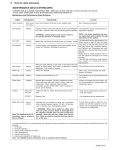
1
USE & CARE
Model AE (8")
Model AF (10")
Dear Customer
Congratulations on the purchase of your new Delta-Q Autoclave. The technical documentation provided is designed as a part of
this product. Always keep this documentation handy. The Use & Care Manual describes the 8” and 10” models. Please read the
instructions and get to know the autoclave. Please carryout maintenance according to relevent instructions.
Pelton & Crane
TABLE OF CONTENTS
Important Safety Instructions ..................................................................................................................................................... 3
Familiarization ............................................................................................................................................................................. 6
Operating Features ............................................................................................................................................................. 6
Safety Features .................................................................................................................................................................. 7
Visual Displays ................................................................................................................................................................... 7
Switch Functions ................................................................................................................................................................ 6
Audible Signals ................................................................................................................................................................... 8
Program Parameters ........................................................................................................................................................... 8
Installation .................................................................................................................................................................................... 9
Programming ............................................................................................................................................................................. 10
Operation ................................................................................................................................................................................... 11
Important Sterilization Practices ........................................................................................................................................ 11
Preparation and Loading ................................................................................................................................................... 12
Operating Steps ................................................................................................................................................................ 13
Maintenance ............................................................................................................................................................................... 14
Maintenance and Performance Schedule .......................................................................................................................... 14
Cleaning Procedure .................................................................................................................................................... 15 -16
Trouble Shooting Guide ..................................................................................................................................................... 17
Self-Diagnostic Check ...................................................................................................................................................... 19
Operating Alarms .............................................................................................................................................................. 20
Options ....................................................................................................................................................................................... 21
Installation and Servicing Checklist ......................................................................................................................................... 22
-2-
! IMPORTANT SAFETY INSTRUCTIONS !
Caution! Personal Safety
• To avoid electrical shock, never insert plug into outlet with
wet hands.
• Do not attempt to open door unless pressure gauge reads
“0” or injury may result.
• Do not operate Autoclave in area containing combustible
gases.
• Do not place Autoclave within 6 feet of patient.
• Routinely inspect power cord for cuts and abrasions.
Discontinue use and have authorized service representative replace cord if damaged.
• Protect your hands from contact with soiled instruments to
prevent serious infections. Wear heavy rubber gloves when
handling instruments.
Warning! To Avoid Serious Burns:
-
-
Do not open door during sterilization cycle.
Stand to one side when opening door after
sterilization cycle and do not place hands or
face over door.
Use a tool or hot pad to remove trays and avoid
touching chamber walls.
Stand away from door after the sterilization cycle is
completed. Liquids may still be in the chamber and
can cause serious burns.
Ensure unit is properly leveled. Follow the Installation Instructions on page 9.
When performing safety valve maintenance (pg. 14)
stand clear of discharge area (lower right corner at
rear of unit).
Caution! Check weekly for proper
door switch operation (see pg. 14).
Product Safety
• This unit requires a dedicated circuit (separate branch circuit
only).
• Always use distilled quality water. Tap water will cause
corrosion of chamber and clog valves and filters with mineral
deposits.
• Never operate unit outside the specified voltage range (see
data plate on back of unit).
• Do not use steel wool or steel brushes on stainless steel.
Metal pads will damage chamber.
• Use only manufacturer’s replacement parts/accessories.
Failure to do so may cause poor performance.
• Refer servicing to authorized service representative.
• Do not position the unit so that it is difficult to reach the
circuit breaker on the power plug.
WARNING: If unit is operating in high altitude,
adjustments to time, temperature or pressure
may be required. Also, leaking of safety valve
may indicate need for adjustment.
Product Disposal
Caution!
Contact your local authorized
dealer for proper disposal of the
device or the components of the
device to ensure compliance with
your local environmental regulations.
Do not remove cover: Electrical shock
hazard. Refer servicing to authorized
service representative . Disconnect power
before servicing.
DANGER: Do Not attempt to open door with
pressure in the chamber. Avoid direct contact with hot chamber walls or sterilized load.
Use metal handle (8” model only) and gloves.
Warning! —To avoid serious burns —
If used for liquid sterilization, the liquid
must be allowed to cool or the liquid may
boil when exposed to atmospheric pressure. Pelton & Crane does not recommend use of
this device for liquid sterilization.
CAUTION: ANY LIQUIDS THAT ARE STERILIZED
IN THIS UNIT ARE FOR LABORATORY USE
ONLY AND NOT FOR USE IN DIRECT PATIENT
CONTACT.
Interference with electromedical devices:
To guarantee the operational safety of electromedical devices,
it is recommended that the operation of mobile radio telephones in the medical practice or hospital be prohibited.
Strong EMI sources such as electro surgery units or x-ray
units may effect performance. If performance problems occur,
move the unit to another electrical circuit or physical location.
-3-
PRODUCT INFORMATION
Table of Symbols
Program
Power
Hot Surface
Ground
Low Water
Mode
Dry
Printer Connection
Ready
Printer On/Off
Arrows
Sterilize
Attention: Printer Connection Only
CAUTION. Failure to carefully follow the
described procedure may result in damage
to the equipment.
Clear/Start
WARNING. Failure to carefully follow the
described procedure may result in damage
to the equipment and the operator.
Risk of electrical shock present. Make sure
power is disconnected before attempting this
procedure.
-4-
PRODUCT INFORMATION
Specifications
Exterior Dimensions
8” Model12 1/4” high x 20 1/4” deep x 17 1/2” wide
(31.1 cm high x 51.4 cm deep x 44.5 cm wide)
10” Model14” high x 24 5/8” deep x 19 1/4” wide
(35.6 cm high x 62.5 cm deep x 48.9 cm wide)
8” Model
12 1/4”
(31.1cm)
20 1/4”
(44.5cm)
Chamber Dimensions
8” Model8 7/32” inside diameter x 14” useable depth
(21 cm inside diameter x 35.6 cm deep)
10” Model9 7/8” inside diameter x 17 7/16” useable depth
(25.1 cm inside diameter x 44.3 cm deep)
Weight Without Water in Reservoir
8” Model61 lbs. (28 kg)
10” Model84 lbs. (38 kg)
17 ½”
(44.5cm)
Measurement Accuracy
Pressure: +/- 8 kPa (1.16 PSI or .08 bars)
Temperature: +/- 3.6° F (2° C)
Time: +/- 1 second
Power Supply
Both Models110 - 120 Volts, 50/60 Hz or
220 - 240 Volts, 50/60 Hz
10” Model
14”
(35.6cm)
Nominal Current Consumption
8” Model12 Amperes @115 Volts
6 Amperes @230 Volts
10” Model10 Amperes @115 Volts
8 Amperes @230 Volts
24 5/8”
(62.5cm)
19 1/4”
(48.9cm)
Environmental and Storage Limitations
Both ModelsOptimum Operating Temperature Range:
50°F to 104°F
(10°C to 40°C)
Relative Humidity Range:
30% to 75%
Unit is designed for normal dental/medical office environment.
NOTE: If printer is used, its operating temperature is 41°F
to 95°F (5°C to 35°C).
Mode of Operation:
Both Models- Continuous
NOTICE: Manufacturer will make available all information
which will assist the authorized service representative to
repair equipment. Calibration of the power board is to be
done only at the factory.
-5-
FAMILIARIZATION
19
18
20
2
17
3
4
5
6
5
7
8
9
10
11
12
13
15
14
15
OPERATING FEATURES
1. Power Switch/Circuit Breaker (rear of unit)
2.
3.
4.
5.
6.
7.
8.
9.
10.
11.
12.
13.
14.
15.
16.
17.
18.
19.
20.
.
SAFETY FEATURES
The design of the autoclave has these safety features for
your protection:
Door Lock
Door can be opened only when internal pressure is at
atmospheric pressure.
Vent Valve
The vent valve will open and the P-2 alarm will display should
the chamber pressure exceed 240 kPa.
Safety Valve
The safety valve opens as backup protection should the
chamber pressure exceed 262 kPa.
Overheat Protection
Chamber temperature is protected with a surface sensor so
the temperature will not exceed 159°C. It has additional
overheat protection should the temperature of the heating
elements reach 180°C.
Electrical Power Interruption
In case of a power failure during the sterilization cycle,
pressure in the chamber is automatically vented to the
atmosphere and display is blank
Reservoir Fill
Operation Indicator Light
Display Window (Pressure) kPa
Arrow Switches
Display Window (Temp/Time) C/F / Minutes
Clear/Start Switch
Low Water Light
Mode Selection Switch
Mode/Program Display
Power On Switch
Programming Switch
Printer On/Off Switch
Quick Drain Connection (inside door)
Leveling Feet
Door Lock
Safety Valve (rear corner of unit)
Operating Instructions Label
Caution Label
Serial Number Plate (inside door)
-6-
FAMILIARIZATION
VISUAL DISPLAYS
Indicator Lights
“Sterilize” light illuminates to indicate sterilization cycle in progress.
“Dry” light indicates the heater and pump are on for the drying cycle.
“Ready” light illuminates when instruments may be removed from chamber.
Upper Window
Displays Time, Pressure, Clock and Year.
Lower Window
Displays Temperature, Date, Operational Timer, Failure Codes, Power colon “:” (
power button is not activated when main power is ON) and End.
Mode/Program
See Program Parameters, pg. 10.
Low Water
When the water level in the reservoir is too low, the “Low Water” light illuminates.
SWITCH FUNCTIONS
Arrows
Increases or decreases values of digits flashing when programming the system
parameter.
Clear/Start
Controls the start of a sterilizing cycle when unit is in stand-by. Also, used to clear
a cycle and returns unit to stand-by. If depressed with “Power” switch, self-diagnostic check is performed.
Mode Selection
Press to select one of the five sterilization mode programs. (See page 14 for
special mode)
Printer On/Off
Use to switch the printer on or off.
Program
Sets the minutes, hour, day, month and year. Chooses units of temperature and
pressure. Changes the drying time. Also, chooses the Special mode to the parameter desired. It initiates selected display mode during sterilization.
Power
Powers on operating controls. LCD will be visible. If depressed with “Clear/Start”
switch, self-diagnostic check is performed.
Main Power (back of unit)
Depress “I” side of switch to turn unit on. A colon “:” illuminates in the lower
display indicating power is on. Leave switch in the On position.
-7-
FAMILIARIZATION
AUDIBLE SIGNALS
Switches
One beep occurs when depressing switches, except when depressing Power Switch and Arrow switches. When pressing
Arrow or Power Switch, no beep occurs.
Sterilization/Dry Cycle
Five beeps indicate the Sterilization or Drying cycles are complete.
Operational Alarm
Sixty beeps indicates an operational error or alarm. Depress Clear/Start to put unit in standby mode.
Door Open
Continuous beeping indicates the door has been opened during or prior to start of cycle.
PROGRAM PARAMETERS*
Program/Temp**, Pres,
Time**
Items to be Sterilized
1 Unwrapped/
134°C, 216 kPa for 3
minutes
Instruments loose on a tray. Open glass or metal canisters. Heat-resistant rubber tubing
which will not be used in surgical procedure. Any items where 134°C-137°C for 3 minutes
is appropriate.
Loosely wrapped individual instruments.
2 Wrapped/
134°C, 216 kPa for 12
minutes
Wrapped dental handpieces***. Multiple layers of instruments separated by fabric. Instruments in pouches. Wrapped tray of loose instruments. Heat-resistant rubber tubing. Any
items where 134°C-137°C for 12 minutes is appropriate.
3 Packs/
121°C, 115 kPa for 30
minutes
Common groups of surgical instruments in commercially prepared packs. Surgical instruments subject to prolonged storage. Any items, other than liquids, where 121°C for 30
minutes is appropriate.
4 Liquids/
121°C, 115 kPa for 30
minutes
Liquids or gels that could boil or spill out of container. At end of sterilizing cycle, venting is
slowed to allow heat in liquid to dissipate
slowly and eliminate boilovers. Venting occurs at 20 kPa to complete the cycle. There is
NO drying cycle in the “Liquids” mode.
!CAUTION: ANY LIQUIDS THAT ARE STERILIZED IN THIS UNIT ARE FOR
LABORATORY USE ONLY AND NOT FOR USE IN DIRECT PATIENT CONTACT.
Warning! —To avoid serious burns —
If used for liquid sterilization, the liquid must be allowed to cool or the liquid
may boil when exposed to atmospheric pressure. Pelton & Crane does not
recommend use of this device for liquid sterilization.
5 Special/
Programmable to
101°C to 135°C, for 1
to 90 minutes.
Dependent upon parameters user has programmed. Operator is responsible for correct
time and temperature settings for load.
*
For mixed loads, use the longer or lower temperature program (i.e., for loose instruments and surgical dressings in packs, use
“3 Packs”).
** Time and temperatures are minimums.
*** When sterilizing handpieces, check handpiece manufacturer’s recommendations for appropriate sterilization conditions. Use “2
Wrapped” program only if handpieces are able to withstand 134°C-137°C temperature.
The names of the various modes of operation are general categories.
When selecting the mode of operation, take into consideration the density of the individual load and the ability of the steam to
circulate and penetrate wraps. Then determine the correct programmed values to assure sterilization.
-8-
INSTALLATION
B
1.
Remove all packing material from chamber.
2.
Place unit on a level countertop.
3.
Peel protective cover from tape on top of casing and
place operating instruction card (B) (with the
appropriate language for the operator, facing up) on
the tape and press down firmly.
NOTE: If unit has been stored in cold conditions, allow it two hours to warm up to room
temperature before operating.
(813mm - 914mm)
Power Cord Configurations and Ratings.
4.
Plug power cord into a receptacle that is on a
dedicated. Ensure that the circuit has the proper
fuse or breaker to accomodate the maximum power
of the unit. Properly install per you local electrical
codes. (See illustration C).
5.
This unit has been pre-leveled during manufacturing
therefore “NO” leveling is required. However, if the
unit is placed on a surface that is not level then
follow the leveling instructions below:
• Remove all trays from the chamber.
North
America
115 V
15 AMP
• Pour distilled water into chamber.
115 V
20 AMP
• Adjust leveling feet (D) until water comes to the pull
tab of the inline filter assembly (F) (located in the
rear of chamber) and reaches the top of water dam
(G) at the front of chamber.
220 V
13 AMP
• Reinstall trays and tray rest.
• Close door and run one cycle on the unwrapped
cycle according to the operating instructions.
C
IMPORTANT: Carefully read the Programming
Set-up instructions and program unit accordingly. (Refer to page 14).
NOTE: The unit has a special automatic preheat
mode that warms chamber for quicker cycle
times, between 0600 and 1800 hours.
NOTE: If unit is not to be used for extended
period of time. Turn OFF main power switch
located in the back of unit.
F
G
WARNING: Counter top must be wide enough
to support all unit feet. All unit feet must be
securely placed on counter top.
D
-9-
PROGRAMMING
Operator Action
1. Depress “Program” button. Use Arrows to increase or decrease Time
and Month to correct settings.
System Response
Hours (based on military time) and
month (ranges 1 - 12) display flashes.
Note: Properly program the time,
since preheat starts 0600 hours
and stops at 1800 hours.
2. Depress “Program” button a second time. Use Arrows to increase
or decrease Minute and Day to correct settings.
3. Depress “Program” button a third
time. Use Arrows to correctly set
Year and choose to display the Minutes remaining in the sterilization
cycle or the Temperature during
cycle.
4. Depress “Program” button a fourth
time. Use Arrows to select preferred Pressure and Temperature
unit of measure for display.
Minute (ranges 00 - 59) and Day
(ranges 1 - 31) display flashes.
Year (ranges 00 - 99) and Minute or Year
and Temperature display flashes.
Unit of Measure Indicator for Pressure
(kPa, PSI or Bars) and Unit of Measure
Indicator for Temperature (C or F)
display flashes.
5. Depress “Program” button a fifth
time. Use Arrows to increase or decrease Time and Temperature settings for programming “Special”
mode.
“Special” Program mode flashes.
Current settings for Time and Temperature of Special Program are displayed.
6. Depress “Program” button a sixth
time. Use Arrows to increase or decrease Time for Drying cycle.
“Dry” indicator light flashes. Minutes
(ranges 0-99) display flashes. (30
Minutes is the recommended minimum
time which is preset at the factory.)
-10-
OPERATION
Important Sterilization Practices
Caution! Become familiar with the
individual functions of the five (5)
modes to ensure using proper
sterilization cycle. Wrong mode
selection or improper loading may
result in improper sterilization.
• Do Not overload chamber. Refer to “Preparation and Loading”.
Do not exceed maximum loading configuration. Otherwise, inadequate sterilization could result.
• All functions of the sterilizer should be monitored to provide
maximum sterility assurance. We recommend using Pelton &
Crane’s printer to provide a permanent record of actual exposure times and temperatures.
• For additional assurance that minimum sterilizing conditions
have been achieved, good sterilization practices recommend
the use of a quality temperature sensitive process indicator with
each cycle and within each package.
• Since temperature sensitive process indicators do not integrate
sterilization parameters, biological monitoring is recommended
to provide further information in detecting inadequate sterilizer
performance. Biological indicators can be used to integrate the
various cycle parameters and indicate whether sterilization
conditions have been met in a particular cycle.
• Thoroughly clean instruments before placing them in the sterilizer. Processing instruments with debris or blood contamination impedes sterilization and may result in staining and/or damage to instruments or sterilizer. Use no cleaners with chlorine.
• Follow manufacturer’s recomendations for the individual items
before sterilizing.
• Use proper sterilization and instrument handling as recommended by ADA, CDC, AAMI, AORN and OSAP guidelines.
• Do Not use staples, pins or other devices which will puncture the packaging material as sterility may be compromised.
• Do Not sterilize instruments while running cleaning cycle.
• Sort instruments by type of metals. Do Not mix carbon steel
stainless steel, brass, aluminum, chrome or other types of
metals as plating may occur.
• Place loose instruments on towel or absorbent paper.
• Wrapped packages Must Not touch sides.
• Place pouches with paper side down.
• Place open containers tilting downward in tray.
• Do Not attempt to sterilize long tubing as steam may not
penetrate the full length.
• Do Not wrap instruments too tightly. Inadequate sterilization may result from improper wrapping or placing too many
instruments per package.
Sterilization Assurance
Clinical Record Keeping
• Review daily and weekly records to substantiate procedures taken to assure sterilization.
Techniques for Sterilization Assurance
• Use internal sterilization process indicators inside all sterilizer
loads to verify gross heat penetration.
• Once per week, use a biological spore test indicator (BI) designed for gravity steam sterilizer operating at 121°C (Attest®,
Biological Monitoring System, 3M, St. Paul, MN; or equivalent)
or 134°C (EZ Test, Bozeman, MT) to test each type of cycle
used at your facility.
- Load sterilizer to maximum load used at your facility.
- For “Wraps” and “Packs” Cycle, place biological indicator inside wrap or pack containing instruments and then place this
pack or wrap in front lower tray of the sterilizer. (This is the
cold spot, i.e. lowest temperature condition.)
- For Unwrapped Cycle, load trays with instruments, place biological indicator in front lower tray of sterilizer.
CAUTION: ANY LIQUIDS THAT ARE
STERILIZED IN THIS UNIT ARE FOR
LABORATORY USE ONLY AND NOT FOR
USE IN DIRECT PATIENT CONTACT.
Follow manufacturer’s instructions for using all test materials and maintaining good clinical records.
• Follow Maintenance schedule on page 24 to ensure proper
operation of the autoclave.
• Note: Indicator tape should not be used as a sterilization indicator. It has a temperature sensitive stripe that
changes color with temperature only.
-11-
OPERATION
Preparation and Loading
• Clean and dry items thoroughly.
• Properly seal items in wrap or pouch if load is to
be kept sterile during storage. Recommended wrap/
pouch materials are cloth, paper, or paper/poly
pouches. Nylon pouches/tubing are not recommended.
• This unit is not suitable for sterilization of gowns/
fabrics, “porous load”.
• Place temperature sensitive process indicator inside package.
• Place temperature sensitive indicator in front portion of bottom tray.
• Place load on tray with space between instruments or packages so that steam can flow between items.
• Place trays in chamber with adequate space for
steam circulation.
The Following are recommended maximum loading configurations:
Wrapped/Unwrapped Cycle
• Model AE: Total weight not to exceed 1.5 lbs. This is equivalent to approximately 9 handpieces or hinged instruments (average
weight of 2.3 ounces) or 30 hand instruments (average weight of 1 ounce.)
• Model AF: Total weight not to exceed 2 lbs. This is equivalent to approximately 13 handpieces or hinged instruments (average
weight of 2.3 ounces) or 42 hand instruments (average weight of 1 ounce.)
Pack s Cycle
NOTE: When calculating maximum load, use the same weight and instrument equivalencies as specified in the “Wrapped/
Unwrapped”cycle.
• Model AE: Total weight not to exceed 2.5 lbs. One (1) pack in top tray and one (1) in bottom tray with pack dimensions not to
exceed 5² x 7² x 1/4².
• Model AF: Total weight not to exceed 2.5 lbs.. Two (2) packs in top tray and one (1) in bottom tray with pack dimensions not to
exceed 5² x 7² x 1 1/2².
CAUTION: ANY LIQUIDS THAT ARE STERILIZED IN THIS UNIT ARE FOR
LABORATORY USE ONLY AND NOT FOR USE IN DIRECT PATIENT CONTACT.
Dental Handpieces: Check handpiece manufacturer’s recommendations for
appropriate sterilization conditions. Use “2 Wrapped” program only if
handpieces are able to withstand 134°C - 137°C temperatures.
-12-
OPERATION
Operating Steps
NOTE: Add distilled water to bottom of filler cup
opening. Ensure water is covering condenser coil
for proper operation.
Add distilled water to reservoir between cycles if
“Low Water”
light is on. Close and latch door.
(power switch for main power
supply is located on the
backside of unit)
D
E
F
• At start of day, depress “Power” switch
(A) to provide power to operating system.
C
B
• Ensure proper mode (B) is selected for
load to be sterilized.
A
• Depress “Clear/Start” (C) switch. Unit
will automatically fill; build up steam
pressure while expelling air; sterilize for
selected time; vent and dry for the
programmed drying time.
• Open door and unload after drying cycle is
complete: “Ready” light (D) is on; five beeps
occur; zero (0) pressure indicated in upper
display window (E) and “End” is displayed in
lower display window (F) if door is not opened
prior to completion of drying cycle.
• Note: Do not run sterilization cycle with drying
until the unit has preheated for 30 minutes. Otherwise, inadequate drying may occur.
• Note: Sterilized items may be removed any
time during the drying cycle. Use caution as items
may be hot and wet. Wet items will not remain
sterile for any length of time.
• Important: Examine each pouch before and
after the sterilization cycle for open seals or tears.
If there is a breach of pouch integrity, reseal in a
new pouch and resterilize.
CAUTION: “5 Special” temperatures set below
121°C should not be used for sterilization, but
for disinfection only.
WARNING: Do Not attempt to open door with
pressure in the chamber. Avoid direct contact
with hot chamber walls or sterilized load. Use
metal handle and gloves.
-13-
MAINTENANCE
CAUTION: Units is in preheat mode between 0600 - 1800 hours. So that units will be cool to the touch, turn off unit at
main power switch (back of unit) 30 minutes before performing maintenance.
Maintenance and Performance Check Schedule
CHECK
Clean
chamber
Door gasket
PROCEDURE
FREQUENCY
After every
25 cycles
Weekly
4 ozs. Omni-Cleaner Plus® per 64 ozs. distilled
water.
Inspect and clean using Omni-Cleaner Plus® or mild
detergent and water. Check for leaks and have leaking
gasket replaced.
WARNING: Leaking gasket could result in harm
to the operator because of escaping steam.
Inspect latch mechanism for signs of wear or improper
closure.
ACTION
See “Cleaning Procedures” on pg. 15.
Call authorized service representative
for replacement gaskets.
NOTE: For proper operation use only
our replacement parts available
through authorized service dealers.
Call authorized service representative if improper
closure or signs of wear are noted.
Door latch
Weekly
Bio Indicator
Weekly
Conduct testing using biological spore test indicator as
described in “Operation, Sterilization Assurance.”
Door switch
Weekly
With door open, attempt to start cycle. If door alarm does Call authorized service representative.
not appear on alarm display, door switch is defective or
requires adjustment. Unit should not operate.
Boiler ring
Weekly
Inspect for deposits.
Clean using non-chlorinated pad
which contains no metals.
Operation
check
Weekly
Perform test described on page 11.
Call authorized service representative
if failure occurs.
Water filters
Monthly
Remove filter in chamber. Put filter in unltrasonic cleaner.
Scrub with small soft brush under running water and
replace filter. When replacing, make sure filter in chamber touches center bottom wall of chamber to ensure
proper draining.
If filters are clogged are will not clean,
call an authorized service representative for replacement filters.
Every Service Call
Inspect air filter for cracks and loose tubing connections.
Have service representive remove
the cover and inspect.
Annually
Replace Filter
Call authorized service representive.
Manually pull ring (located on upper rear of chamber)
when chamber pressure reaches 121 kPa. When pressure is relieved, valve automatically retracts.
If valve does not open or does not
completely seal off after operation,
turn off “Power” and call authorized
service representative for replacement.
Air filter
Safety
valve ring
Every 3
months
WARNING: When ring is pulled on safety valve
with unit under pressure, steam is discharged
from the chamber straight down the pipe at high
temperature. When you pull ring, steam exits
out bottom. Make sure path is clear and that
your hand is out of the way.
If test fails, do not use other items in with that
load. Ensure that “Important Sterilization Practices”
and “Preparation and Loading” sections in this
manual have been followed.
Retest using an empty chamber, then retest with
properly packaged and loaded chamber.
If test still fails, discontinue using sterilizer and
contact an authorized service representitive.
It is recommended that you annually have your sterilization system inspected by an authorized service and retain maintained
records for the following:
1. Hi-Pot Test
CAUTION: Unauthorized
2. Terminal Inspection
maintenance can damage
3. Internal Tubing inspection for leaks.
sterilizer and will void
4. Filter replacements.
5. Ground continuity test.
manufacturers warranty
6. Internal wire inspection for frayed wire.
Note: For detailed service instructions, refer to autoclave Service Manual.
-14-
MAINTENANCE
Cleaning Procedures
NOTE: Proper cleaning at regular intervals is
essential, since mineral deposits, debris or trash
may cause the unit to malfunction.
Draining Reservoir
With the door open, locate the quick drain connection
(A) at the lower right corner of the face plate. Press
the drain tube connector (B) provided with the unit into
the connection on
the face plate. This opens the drain line and draining of
the reservoir will begin immediately.
Normal Chamber Cleaning
Drain the reservoir using quick connect drain tube. Mix
Omni-Cleaner Plus® with distilled water according to directions on bottle. Pour into reservoir. Run one “Unwrapped” cycle (Note: It is not necessary to complete
drying cycle). Drain reservoir. With the drain tube in
place, pour one to two gallons of water into the reservoir
until the drained water is clear.
This will remove excess suds. Wipe inside of the chamber with soft cloth.
A
B
WARNING: Do Not sterilize instruments
while cleaning autoclave.
Pour half gallon distilled water into reservoir. Run one
“Unwrapped” cycle
(Note: It is not necessary to complete drying
cycle). Wipe the inside of the chamber, the boiler ring
(C) and the door gasket. Fill reservoir with distilled
water. Autoclave is ready for use.
Cleaning Deposits and Discoloration on Stainless
Steel
For deposits not removed by detergent solution, use a
non-chlorinated, non-metallic scouring pad such as
Scotch-Brite® or a powder such as Bon-Ami®.
CAUTION: Do not use ordinary steel wool
or steel brushes on stainless steel. Pads
containing metal will damage chamber and
cause instruments to be stained with rust.
C
CAUTION: Do not use chlorinated
cleaners. Doing so will cause corrosion.
Rub in direction of pattern or grain of the metal. Clean
stainless steel surfaces contaminated with discoloration
with a 5% solution of warm oxalic acid.
-15-
MAINTENANCE
Cleaning Procedures (cont’d)
Cleaning Boiler Ring (C)
Clean boiler ring using a non-chlorinated, nonmetallic scouring pad such as Scotch-Brite®.
Cleaning Door Gasket (D)
Clean door gasket with Omni-Cleaner Plus® or
non-chlorinated detergent and water. Note: If
residue is allowed to accumulate, the seal could
be affected and leaks may occur.
A
B
Cleaning/Disinfecting Exterior Surfaces
Clean all exterior surfaces with mild detergent and
water using a sponge or cloth. Disinfect exterior
surfaces using an iodophor (Biocide, Biotrol, Inc.,
or equivalent).
CAUTION: Do Not use any disinfectant on
interior stainless steel surface. Damage to
the chamber and/or trays may result.
CAUTION: Do not use instruments if unit
fails to complete cycle.
C
D
-16-
MAINTENANCE
Trouble Shooting Guide
PROBLEM INDICATORS
PROBLEM CAUSE
CORRECTIVE ACTION
Clean with Omni-Cleaner Plus®
Mineral buildup on chamber wall or wa- Minerals in water or on contents (using
(part no. 30 06 934) following instructions
ter spots on chamber and contents.
tap water).
on bottle. Scrub chamber with Bon-Ami®
or Scotch-Brite®. Use distilled water only.
Unit takes an excessive amount of time Load too large. Steam pushing out air Remove some packages/articles for faster
(over 20 minutes from a warm start)
too slowly.
steam flow.
to reach required sterilization temperature.
Call authorized service representative.
Leak in valves.
Follow “Preparation and Loading” instructions.
Moisture evident in packs or wraps after Overloaded chamber.
Chamber tilted forward resulting in waLevel unit properly. Refer to “Installation Instructions,”
drying cycle.
ter left in chamber after venting.
page 12 for proper unit leveling procedure.
Fill line filter (inside chamber) clogged
Clean filter in ultrasonic cleaner. Adjust fill line filter to
center bottom of chamber. Replace if air and water
or not properly installed, resulting in too
cannot freely pass through filter.
much water remaining in chamber after
venting.
Increase drying time. (see Programming)
Drying time not adequate for load.
Call authorized service representative.
Drying air intake filter clogged.
Call authorized service representative.
Drying pump not operating properly.
Wait 30 minutes to start sterilizing cycle after power
Unit run without preheating.
is turned on.
Wet layer in pack.
Inadequate drying air penetration due to tight
pack wrapping or condensation from packs.
Inspect pack for proper wrap. Basins, kits and other
utensils should be prepared as individual
packs.
Caution: Use only approved packs.
Water collects in bottom of chamber when unit
is not in “Fill” cycle.
Leaking fill/solenoid valve.
Call authorized service representative.
Hole in condensing coil.
Call authorized service representative.
Unit drips on counter from door during cycle.
Debris on gasket or door ring. Cut in gasket.
Clean gasket and door ring or replace gasket if cut.
Water comes out of fill opening on top of
case when unit vents to reservoir.
Reservoir overfilled.
Drain some water. Fill to bottom of openings
in fill cup.
Cracked condenser tube causing turbulence
under fill opening.
Replace condenser tube.
No power to wall receptacle.
Reset building circuit breaker.
Master power switch is not turned on.
Be sure main power switch/circuit breaker on back
of unit is on.
Defective electronics.
Call authorized service representative.
Electroplating.
Do not mix dissimilar metals in the same package.
Separate carbon steel, aluminum chrome and brass
from stainless steel trays by using a tray liner.
Cold sterilization residue.
Wash thoroughly before loading.
Chlorine stains.
Do not use toweling or packaging which may contain chlorine bleach residue.
Chamber surfaces become cracked.
Chlorine.
NEVER use chlorine cleansers or materials in
chamber. Wrapping materials should not be
cleaned with chlorinated bleaches. Use only distilled water. Call authorized service representative.
Unit clicks, but no display; unit shuts off intermittently in mid-cycle.
Malfunctioning connector cable.
Call authorized service representative.
Door leaks on 10 inch autoclave.
Lip of tray rest is in front of the water dam.
Place lip behind water dam.
Instruments become rusted or stained.
Minerals and metals in reservoir or chamber.
Use only distilled or deionized water for autoclaving. Clean and flush reservoir/chamber.
Unit will not turn on.
Dark stains on instruments.
-17-
MAINTENANCE
Trouble Shooting Guide
PROBLEM INDICATORS
Positive biological indicator
PROBLEM CAUSE
Insuffcient steam penetration.
Wrong type of biological indicator for this
sterilizer, wrong cycle used or biological
indicator has expired.
CORRECTIVE ACTION
Reduce load weight or check if load is packed properly.
Check bioligical indicator instructions to make sure
indicator is for a gravity type sterilizer. Check that
indicator is correct; one for cycle times and temperatures being run. If necessary, contact your biological indicator representative.
WARNING: Do not use instruments if unit fails to complete cycle.
-18-
CHECK
DISPLAY
COMPONENTS
CHECKED
Fill/vent solenoid
OPERATIONAL
FUNCTION
CHECKED
Solenoid operation and
electrical continuity.
MAINTENANCE
Self-Diagnostic Check
Automatic Check
The autoclave automatically performs a diagnostic selfcheck on nine key components for operational continuity
each time the main power switch (toggle switch located
at rear of unit) is turned on.
An additional check may be made by the following
procedure:
Dump solenoid
Solenoid operation and
electrical continuity.
Operational Check
switch and “Clear/Start”
Depress “Power On”
switch at the same time. The autoclave beeps once,
signaling the beginning of the self-diagnostic procedure.
Bellows solenoid
Steam sensor
Solenoid operation and
electrical continuity.
Electrical continuity and
parameter check.
During the first four seconds, check that all display
segments illuminate. If segments do not illuminate, call
an authorized service representative. This problem can
give the operator incorrect information if not repaired.
After self-diagnostics, the unit returns to stand-by. The
lower window displays any error found during the
Operational or Automatic self-diagnostic check procedure. See table at left for explanation of display.
Call an authorized service representative if an unsatisfactory check is indicated.
Surface sensor
Electrical continuity.
Battery
Parameter memory for
specials mode (e.g.,
clock settings).
Pressure transducer
Nominal operating
parameter.
Line voltage
Adequate voltage.
-19-
MAINTENANCE
Operating Alarms
Eight alarms can occur during a sterilization cycle. All alarms are indicated by a “beeping” sound for one minute (or until
“Clear/Start” is depressed) and an alarm display in the lower display window. The alarm display will remain visible until the
problem is corrected or until the “Clear/Start” button is depressed.
DISPLAY
CAUSE
ACTION
Chamber door not fully closed.
Shut door properly.
Problem with door switch.
Check door switch (see Maintenance, pg. 24).
Not enough water in chamber.
Inspect for clogged reservoir and chamber filter. Clean or
replace filter as necessary.
Chamber has boiled dry.
See that there is sufficent water in reservoir. Clear unit.
Restart cycle. If problem recurs, turn off “Power” switch and
call an authorized service representative.
Not enough water in chamber.
Inspect for clogged reservoir and chamber filter. Clean or
replace filter as necessary.
Leak in gasket.
Check door gasket and chamber sealing surface for debris
or cuts and clean or replace as needed.
Failure to fill properly. Failure to seal against
pressure.
Turn off “Power” switch and call an authorized service representative.
Chamber overloaded.
Check chamber for proper loading and remove some packages/articles which may be impeding proper steam circulation.
More than 10-minute lapse during air bleeding
process.
Check chamber for proper loading and remove some packages/articles which may be impeding proper steam circulation.
Door opened during temperature rise.
Shut door properly.
More than a 3-minute lapse during sterilization
countdown.
Clear unit. Restart cycle. If problem recurs, turn off “Power”
switch and call an authorized service representative.
Add distilled water to reservoir between cycles.
Low water indicator.
Turn off “Power” switch and call an authorized service representative.
Defective pressure-sensing circuit.
Overpressure in the system.
Clear unit. Restart cycle. If problem recurs, turn off
“Power” switch and call an authorized service representative.
Temperature is less thant 10° C. Defective
steam sensor.
Let unit warm up before operating. Turn OFF power switch
and call an authorized service technician.
Steam temperature too high.
Turn off “Power” switch and call an authorized service representative.
-20-
OPTIONS
Tray Clip Installation for Additional Trays
To install additional European trays into 8” autoclave, first
insert tray rack (A), then slide clips over middle (B) and top C
tray rest rods and let the outside edges (D) of the lips rest
against the wall of the autoclave. Tray rest will then hold four
open trays.
To install additional trays into 10” autoclave, first snap upper
(E) and middle F pair of clips onto rods. Bottom edge of top
clip should wrap over middle rod, next to the bottom edge of
the top clip. Insert tray rack into autoclave. Finally, insert
bottom (short) set of clips (G) onto bottom rods so that they
line up with the top clip, letting the outside edge (H) rest
against the wall of the autoclave. Tray rest will then hold six
open trays.
DELTA Q 8”
Time/Temperature Recorder
The 120V Time/Temperature Recorder User Manual is
P/N 15 26 818.
The Time/Temperature Recorder works in conjuction with the 8”
and 10” model autoclaves to provide complete sterilization
records of temperature, pressure and time of sterilization
cycles.
Refer to autoclave Time/Temperature Recorder Manual for
complete installation and operating instructions.
HU-Friedy/European Cassette Rack
(P/N 024338) for 10” autoclave.
IV. European Cassette Rack (P/N 023554)
for 8” autoclave.
DELTA Q 10”
-21-
INSTALLATION AND SERVICING CHECKLIST
Verify the following after installation or servicing of the unit if applicable:
All manuals are present.
All labels are present and legible.
No mechanical damage on new installations.
The chamber filter is positioned and touches the bottom center of the chamber.
The unit is connected to the correct power source.
The unit is setting on a level surface.
The air tube inside the chamber is properly installed.
The reservoir is full of distilled water only.
When the clear/start switch is pressed the display comes on.
The door latch opens and closes properly.
When depressing the mode selection switch, the unit changes programs.
While running the unit there is no water or steam leaking from the chamber or tubing.
If optional printer is connected and after starting a cycle, the printer starts to print periodically through the cycle.
The unit passes a Hi-Pot test.
All terminals are connected securely.
The filters are new.
The unit passes a ground continuity test.
The internal wiring is in good shape and not frayed.
-22-
NOTES
-23-
Pelton & Crane
P.O. Box 7800
Charlotte, NC 28241-7800
USA
©2008, Pelton & Crane
P/N 053169 Rev. 1
06/10
We reserve the right to make any alterations which may be due to technical improvements.