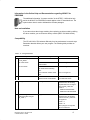
1
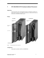
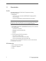
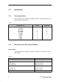
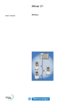
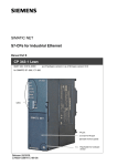
SIMATIC NET
Contents, Product Notes
Manual
CP 342–5
6GK7 342-5DA02-0XE0
version 1 or higher (firmware V4.0.0)
CP 342–5 FO
6GK7 342-5DF00-0XE0
version 1 or higher (firmware V4.0.0)
06/2000
C79000–G8976–C146
Release 01
CP 342-5/342-5 FO Communications Processor
1
Compatibility – Replacing older
Modules
2
How to Install the Module
3
Technical Data
4
Notes on the CE Mark on
SIMATIC NET Products
5
References
6
Safety Guidelines
This manual contains notices which you should observe to ensure your own personal safety, as well as to
protect the product and connected equipment. These notices are highlighted in the manual by a warning
triangle and are marked as follows according to the level of danger:
!
!
!
Danger
indicates that death, severe personal injury or substantial property damage will result if proper precautions
are not taken.
Warning
indicates that death, severe personal injury or substantial property damage can result if proper precautions are not taken.
Caution
indicates that minor personal injury or property damage can result if proper precautions are not taken.
Note
draws your attention to particularly important information on the product, handling the
product, or to a particular part of the documentation.
Qualified Personnel
Only qualified personnel should be allowed to install and work on this equipment. Qualified persons are
defined as persons who are authorized to commission, to ground, and to tag circuits, equipment, and systems in accordance with established safety practices and standards.
Correct Usage
Note the following
!
Warning
This device and its components may only be used for the applications described in the catalog or the
technical description, and only in connection with devices or components from other manufacturers which
have been approved or recommended by Siemens.
This product can only function correctly and safely if it is transported, stored, set up, and installed
correctly, and operated and maintained as recommended.
Trademarks
SIMATICR, SIMATIC HMIR and SIMATIC NETR are registered trademarks of the SIEMENS AG.
Third parties using for their own purpose any other names in this document which refer to trademarks
might infringe upon the rights of the trademark owners.
Copyright E Siemens AG 2000 All rights reserved
Disclaimer of Liability
The reproduction, transmission or use of this document or its
contents is not permitted without express written authority.
Offenders will be liable for damages. All rights, including rights
created by patent grant or registration of a utility model or design, are
reserved.
We have checked the contents of this manual for agreement with the
hardware and software described. Since deviations cannot be
precluded entirely, we cannot guarantee full agreement. However,
the data in this manual are reviewed regularly and any necessary
corrections included in subsequent editions. Suggestions for
improvement are welcomed.
Siemens AG
A&D
Industrial Automation Systems
Postfach 4848, D-90327 Nürnberg
Siemens Aktiengesellschaft
Technical data subject to change.
E Siemens AG 2000
C79000-G8976-C146/01
Contents
Product Notes . . . . . . . . . . . . . . . . . . . . . . . . . . . . . . . . . . . . . . . . . . . . . .
4
1
CP 342-5/342-5 FO Communications Processor . . . . . . . . . .
5
Characteristics . . . . . . . . . . . . . . . . . . . . . . . . . . . . . . . . . . . . . . . . . . . . . . . . . . . . .
Performance . . . . . . . . . . . . . . . . . . . . . . . . . . . . . . . . . . . . . . . . . . . . . . . . . . . . . . .
Transmission Rates . . . . . . . . . . . . . . . . . . . . . . . . . . . . . . . . . . . . . . . . . . . . . . . . .
Basic Data of the DP Interface/DP Master . . . . . . . . . . . . . . . . . . . . . . . . . . . . . .
Basic Data of the DP Interface / DP Slave . . . . . . . . . . . . . . . . . . . . . . . . . . . . . .
Data for S5-Compatible Communication (SEND/RECEIVE interface)
on FDL Connections: . . . . . . . . . . . . . . . . . . . . . . . . . . . . . . . . . . . . . . . . . . . . . . . .
1.2.5 Basic Data for S7 Communication . . . . . . . . . . . . . . . . . . . . . . . . . . . . . . . . . . . . .
1.2.6 Using Parallel Communications Services (Multiprotocol Operation) . . . . . . . .
1.3 Displays and Mode Selector . . . . . . . . . . . . . . . . . . . . . . . . . . . . . . . . . . . . . . . . . .
6
8
8
8
10
11
12
12
14
2
Compatibility – Replacing older Modules . . . . . . . . . . . . . . . .
16
3
How to Install the Module . . . . . . . . . . . . . . . . . . . . . . . . . . . . . . .
22
4
Technical Data . . . . . . . . . . . . . . . . . . . . . . . . . . . . . . . . . . . . . . . . .
23
5
Notes on the CE Mark on SIMATIC NET Products . . . . . . . . .
24
6
References . . . . . . . . . . . . . . . . . . . . . . . . . . . . . . . . . . . . . . . . . . . .
25
1.1
1.2
1.2.1
1.2.2
1.2.3
1.2.4
Manual CP 342–5 / CP 342–5 FO
C79000–G8976–C146/01
3
Product Notes
Product Notes
Note
All the information in the product information bulletin accompanying the device
described here is up to date and valid and must be read thoroughly.
Compatibility with the Previous Version
The CP 342–5 described here can be used to replace the following CPs
– CP 342–5
– CP 342–5
6GK7 342–5DA00–0XE0
6GK7 342–5DA01–0XE0
The CP 342–5 FO and CP 342–5 are compatible in terms of function.
Note
Please note the extended functions and restrictions as described in Chapter 2
of this manual!
4
Manual CP 342–5 / CP 342–5 FO
C79000–G8976–C146/01
1
CP 342-5/342-5 FO Communications Processor
Application
The CP 342-5/342-5 FO communications processor is intended for operation in a
programmable controller of the SIMATIC S7-300 series. It allows the S7-300 to be
connected to a PROFIBUS fieldbus system.
Design
CP 342-5
(9-pin sub-D female
connector)
CP 342-5 FO
(Duplex sockets for optical
connection)
Status and error
displays
Mode selector
Connection for power supply
and functional ground
Figure 1
Front View of the CPs 342-5 / 342-5 FO
Configuration
Configuration is possible via MPI or LAN/PROFIBUS.
Manual CP 342–5 / CP 342–5 FO
C79000–G8976–C146/01
5
1.1
Characteristics
Services
The current version of the CP 342-5/342-5 FO supports the following
communication services:
S
PROFIBUS-DP
– as DP master class 1 and class 2 (PROFIBUS-DP complying with EN
50170, DP Master)
– as DP slave (PROFIBUS DP complying with EN 50170, DP Slave)
Note
Note however, that the CP 342-5/342-5 FO can only be operated as DP master or
DP slave but not both. The DP mode can also be completely deselected.
S
S5-compatible communication (SEND/RECEIVE interface) on FDL connections
of the following types:
– Specified FDL connections
– Free layer 2 connections (SDA, SDN)
– Broadcast
– Multicast
S
S7 communication and PG/OP communication
– PG functions (including routing)
– Operator control and monitoring functions (HMI)
– Server for data exchange using communication FBs
The services of the CP 342-5/342-5 FO listed here can all be used at the same
time independent of each other.
PG Functions with
6
S
upload / download of FM modules
S
Configuration / diagnostics
S
Routing
Manual CP 342–5 / CP 342–5 FO
C79000–G8976–C146/01
Module Replacement without PG
The CP supports the option of storing the CP configuration data on the CPU. If you
use this option, you can replace a module without having to download the
configuration data from the programming device.
The configuration data are then stored in the load memory of the CPU. The
non-volatile storage of the configuration data on the CPU is guaranteed by battery
backup or by using an EPROM module card.
Configuration
For configuration, you require STEP 7, version V5.1 or higher; for FDL connections
and diagnostic functions, you require the NCM S7 for PROFIBUS optional package
supplied with STEP 7.
Note
If you modify the bus parameters in the configuration data, you can only download
the configuration data to the CP via MPI!
Manual CP 342–5 / CP 342–5 FO
C79000–G8976–C146/01
7
1.2
Performance
1.2.1
Transmission Rates
The transmission rate is set with the SIMATIC STEP 7 configuration software. The
following values are permitted:
Table 1-1
1.2.2
Transmission rate
CP 342-5
CP 342-5 FO
9.6 Kbps
19.2 Kbps
45.45 Kbps
93.75 Kbps
187.5 Kbps
500 Kbps
1.5 Mbps
3 Mbps
6 Mbps
12 Mbps
n
n
n
n
n
n
n
n
n
n
n
n
n
n
n
n
n
–
–
n
Basic Data of the DP Interface/DP Master
General Data
The following data are important if you want to operate the CP 342-5/342-5 FO as
a DP master:
Table 1-2
Feature
Number of DP slaves that can be operated
Explanation / Values
124 maximum
Size of the DP data areas (total):
– DP input area
– DP output area
2160 bytes maximum
2160 bytes maximum
Size of the DP data areas (per DP slave):
– DP input area
– DP output area
244 bytes maximum
244 bytes maximum
Size of the DP diagnostic data:
240 bytes per DP slave
8
Manual CP 342–5 / CP 342–5 FO
C79000–G8976–C146/01
Extended Master Functions
The CP 342-5/342-5 FO supports the following:
S
SYNC/FREEZE (acyclic)
S
Shared input/output (acyclic)
S
Activating/deactivating DP slaves
S
Modifications during runtime
– own PROFIBUS address
– DP mode (no DP, DP master, DP slave active/passive)
S
Hardware interrupts / diagnostic interrupts
Hardware and diagnostic interrupts do not need to be evaluated in the user
program. Hardware and diagnostic interrupts are acknowledged automatically
by the CP.
You can use single diagnostics to obtain interrupt information.
Reaction Times of a DP Master
To calculate the reaction times when operating the module as a DP master, the
runtime of the function blocks required for DP processing in the S7-300 CPU
(DP_SEND, DP_RECV) is the decisive factor.
Table 1-3
Components
Runtime on the CPU 314-1
(6ES7 314–1AE04–0AB0)
1)
Explanation / Values (Guidelines)
Per DP_SEND block call:
Per DP_RECV block call:
S 0,2 – 3,4 ms at 16 bytes
S 0,2 – 5,9 ms at 240 bytes 1)
S 0,3 – 3,5 ms at 16 bytes
S 0,3 – 6,9 ms at 240 bytes 1)
At data lengths > 240 bytes: The data is transferred segmented. This then involves several block calls.
Note
The reaction times listed above are only intended as a guideline and only apply to
a single-master configuration when no other services (for example PG functions)
are processed on the CP.
Manual CP 342–5 / CP 342–5 FO
C79000–G8976–C146/01
9
1.2.3
Basic Data of the DP Interface / DP Slave
The following characteristics are important for successful data transfer to a DP
slave:
Table 1-4
Explanation / Values
Feature
Device database file (*.GSD)
File name:
CP 342-5:
CP 342-5 FO:
SIEM8093.GSD
SIEM8095.GSD
You can obtain device database files as follows:
S By modem from the mailbox in the Interface Center, Fürth
Tel. 0911-737972 (from outside Germany +49-911-737972
S On the Internet
http.\\www.ad.siemens.de under “Support, Training and
Service...Customer Support, Downloads”
Vendor ID
CP 342-5:
CP 342-5 FO:
8093H
8095H
Size of the DP data areas:
– DP input area
– DP output area
240 bytes maximum
240 bytes maximum
Min. slave interval
2 ms
SYNC / FREEZE
not supported
User parameter assignment data
3 bytes; value: 00 00 00 (fixed)
User diagnostic data
0 bytes
Reaction Times of a DP Slave
To calculate the reaction times when operating the module as a DP slave, the
runtime of the function blocks required for DP processing in the S7-300 CPU
(DP_SEND, DP_RECV) is the decisive factor.
Table 1-5
Components
Runtime on the CPU 314-1
(6ES7 314–1AE04–0AB0)
10
Explanation / Values
Per DP_SEND block:
Per DP_RECV block:
S 0,3 – 3,2 ms at 16 bytes
S 0,2 – 5,7 ms at 240 bytes
S 0,3 – 3,5 ms at 16 bytes
S 0,3 – 6,4 ms at 240 bytes
Manual CP 342–5 / CP 342–5 FO
C79000–G8976–C146/01
Note
The reaction times listed above are only intended as a guideline and only apply
when no other services (for example PG functions) are processed on the CP.
1.2.4
Data for S5-Compatible Communication (SEND/RECEIVE interface) on FDL Connections:
The following data are important when operating FDL connections (Specified, Free
Layer 2 (SDA and SDN), Broadcast, Multicast):
Table 1-6
Feature
Explanation / Values
Total number of FDL connections that can be
operated.
maximum 16
Size of the transferable data area for FDL
connections
maximum 240 bytes per specified FDL connection
(for sending and receiving);
Free layer 2, broadcast and multicast:
Up to 236 bytes of user data can be transferred per
job. The job header occupies an additional 4 bytes.
Reaction Times of FDL Connections
To calculate the reaction times when operating with FDL connections, the runtime
of the function blocks required in the S7-300 CPU (AG_SEND, AG_RECV) is the
decisive factor.
Table 1-7
Explanation / Values
Components
Runtime on the CPU 314-1
(6ES7 314–1AE04–0AB0)
Manual CP 342–5 / CP 342–5 FO
C79000–G8976–C146/01
Per AG_SEND block:
Per AG_RECV block:
S 0,2 – 3,2 ms at 16 bytes
S 0,2 – 5,7 ms at 240 bytes
S 0,2 – 3,5 ms at 16 bytes
S 0,3 – 6,4 ms at 240 bytes
11
1.2.5
Basic Data for S7 Communication
The following characteristic data are important for operating S7 connections:
Table 1-8
Explanation / Values
Feature
16 maximum 1)
Number of S7 connections that can be operated
1) The actual number of S7 connections that can be operated depends on the CPU type you are using. There
are further restrictions if you operate in mixed mode. Refer to Section 1.2.6 for more information.
1.2.6
Using Parallel Communications Services (Multiprotocol Operation)
Performance
If you want to use the available communications services at the same time, there
are restrictions in terms of communication performance.
The following table shows the transmission rate for FDL connections dependent on
the following:
S
The frame length (number of bytes)
S
The number of connections
The values were measured when sending and receiving in direct succession (at a
transmission rate of 1.5 Mbps, bus profile universal, two stations, mode “no DP”).
Table 1-9
Number of FDL Frames per Second
Number of
connections
1
4
8
16
1 byte
77 / s
92 / s
92 / s
92 / s
100 bytes
73 / s
88 / s
88 / s
88 / s
240 bytes
67 / s
82 / s
83 / s
84 / s
Frame length
Note
Recommendation: In the mixed mode – DP + FDL + S7 functions – a delay time
should be selected.
12
Manual CP 342–5 / CP 342–5 FO
C79000–G8976–C146/01
Number of Connections in Mixed Mode
If you use a connection configuration involving the maximum number of FDL
connections (16) and the use of DP at the same time, the maximum number of S7
connections reduces from 16 to 12.
Manual CP 342–5 / CP 342–5 FO
C79000–G8976–C146/01
13
1.3
Displays and Mode Selector
LED Display of the CP Mode
The four LEDs on the front panel provide information about the mode of the CP
coded as shown below:
Table 1-10
SF (red)
BUSF (red)
RUN
(green)
STOP
(yellow)
CP Mode
Starting up (STOP–>RUN)
Running (RUN)
Stopping (RUN–>STOP)
Ready for firmware download (mode
active for 10 seconds)
Loading firmware
Waiting for firmware update (CP
currently has incomplete firmware)
Stopped (STOP)
Stopped (STOP) with error
Running (RUN) with problems on
PROFIBUS
Running (RUN) with error on DP slave(s)
Module fault or error/ system error
Key:
on
off
flashing
Note
Refer to the NCM S7 for PROFIBUS /2/ manual for detailed information about
operating modes.
14
Manual CP 342–5 / CP 342–5 FO
C79000–G8976–C146/01
Controlling the Operating Mode
There are different ways in which you can control the operating mode of the
CP 342-5/342-5 FO, as follows:
S
Using the mode selector
S
Using the NCM S7 for PROFIBUS configuration software
S
SIMATIC Manager in STEP 7
To be able to control the CP mode from STEP 7 / NCM S7 for PROFIBUS, the
mode selector must be set to RUN.
Mode Selector
You can set the following operating modes with the mode selector:
S
Switch from STOP to RUN:
The CP enters configured and/or loaded data in the work memory and changes
to the RUN mode.
S
Switch from RUN to STOP:
The CP changes to the STOP mode. Established connections (FDL and S7
connections) are terminated.
This affects DP operation as follows:
– DP slave mode: the CP is no longer involved in data transfer.
– DP master mode: the mode is “OFFLINE”.
In the STOP mode, it is possible to configure the CP 342-5/342-5 FO and run
diagnostic functions.
Note
Refer to the manual /2/ for detailed information about downloading a database to
the CP.
Manual CP 342–5 / CP 342–5 FO
C79000–G8976–C146/01
15
2
Compatibility – Replacing older Modules
Replacing Modules
The table below describes the steps involved when replacing an older module with
one of the modules described here:
Table 1-11
Previously Used Module
6GK7 342-5DA00-0XE0
Steps in Configuration
Supply the new module with the adapted configuration as described
below:
1. In STEP 7 / HW Config, replace the previously configured CP
342-5 with the new module (you will find this in the hardware
catalog).
2. Save, compile and download the configuration data to the CPU or
CP again.
6GK7 342-5DA01-0XE0
Case a: Unchanged configuration
If you do not require any extension of the functionality provided by
the previous CP (such as amounts of data), you do not need to make
any changes in the configuration.
When commissioning, you then only need to remember the following
difference:
S If you selected the option of storing the configuration data of the
CP you are replacing on the CPU, the configuration data will be
downloaded to the CP from the CPU automatically when the CP
starts up.
S Otherwise, download the configuration data again to the CP from
your programming device/PC.
Case b: Adapted configuration
If you want to use the extended functionality of the new CP, follow the
steps outlined below:
1. Use the new FCs (version 3.0 or higher; see also page 21) in
your user program.
2. In STEP 7 / HW Config, replace the previously configured CP
342-5 with the new module (you will find this in the hardware
catalog).
3. Extend the configuration according to your requirements, for
example in the configured connections.
4. Save, compile and download the configuration data to the CPU
and CP again.
16
Manual CP 342–5 / CP 342–5 FO
C79000–G8976–C146/01
Information in the Online Help and Documentation regarding NCM S7 for
PROFIBUS
The additional information “for newer modules” in the STEP 7 / NCM online help
and in the NCM S7 for PROFIBUS manual applies to the CP described here. The
symbol shown here is used to indicated the relevant passages.
Note on Installation
If you cannot close the slot gap resulting from replacing an older module by shifting
the other modules, you must insert a dummy module (6ES7 370-0AA01-0AA0).
Compatibility
The CP 342-5/342-5 FO behaves differently from its predecessors in several ways.
Remember that this affects your user program. The following table provides an
overview:
Table 1-12 Changed Behavior
Topic
1.
Previously
New
DPSTATUS output parameter in
FC DP_RECV
DP master mode:
Bit 6: indicated “overflow of
received data”
Bit 6: is no longer set
DP slave mode:
Bit 3: indicated “no frame from
DP master within watchdog
time”
Bit 3: is no longer set
Bit 4: indicated “overflow of DP
data”
Bit 4: is no longer set
2.
DP modes
A distinction was made
between STOP and OFFLINE.
The STOP mode is represented
by the OFFLINE mode.
3.
Setting the current DP mode
– is supported –
In the version of the CP 342-5
described here, the following
job parameters are not supported for FC DP_CTRL with
CTYPE 4:
S RUN with AUTOCLEAR
S RUN without AUTOCLEAR
4.
Cyclic reading of the
input/output data using FC
DP_CTRL 1)
– supported
In the version of the CP 342-5
described here, the following
services of FC DP_CTRL are
not supported:
CTYPE = 7
CTYPE = 8
These job types are rejected
with the code 8311H.
Manual CP 342–5 / CP 342–5 FO
C79000–G8976–C146/01
17
Table 1-12 Changed Behavior, continued
Topic
5.
Triggering cyclic global control
with FC DP_CTRL 1)
Previously
– supported
New
DP master mode:
In the version of the CP 342-5
described here, the following
services of FC DP_CTRL are
not supported:
CTYPE = 1
These job types are rejected
with the code 8311H.
6.
Triggering acyclic global control
with the CLEAR job or with FC
DP_CTRL 1)
– supported
DP master mode:
In the version of the CP 342-5
described here, the following
services of FC DP_CTRL are
not supported:
CTYPE = 0 command mode =
CLEAR
These job types are rejected
with the code 8318H.
7.
Triggering acyclic global control
for group 0 using FC DP_CTRL
– supported
DP master mode:
In the version of the CP 342-5
described here, the following
services of FC DP_CTRL are
not supported:
1)
CTYPE = 0 group select = 0
These job types are rejected
with the code 8318H.
8.
Consistency in data transfer
between CP and user program
Maximum DP data area:
Maximum DP data area:
S 240 bytes in the DP master
S 2160 bytes in the DP
mode
S 86 bytes in the DP slave
mode
master mode
S 240 bytes in the DP slave
mode
S You will find further information on consistency following this table
9.
FCs for DP mode
Depending on the
configuration, the older FC
types (FC91 to 94) can be used
alongside the new FC version
(FC1 to 4).
S You will find further information on the FCs following this table
10. FCs: Evaluate general properties and codes on the call interface
The additional information “for
newer modules” applies to the
CP described here.
Description in the online help or
in the NCM S7 for PROFIBUS
manual
The passages are highlighted
by this symbol:
18
Manual CP 342–5 / CP 342–5 FO
C79000–G8976–C146/01
Table 1-12 Changed Behavior, continued
Topic
11. Deterministic sending/receiving
of data – coordination between
CPU and CP/PROFIBUS
Previously
In the cyclic DP mode, the job
confirmation on the FC
interface contains the
confirmation of the transfer to
PROFIBUS.
New
In the cyclic DP mode, the
execution cycle on the CPU is
independent of the cycle on the
CP.
Sending data: The confirmation
of the job does not include
confirmation of the transfer to
PROFIBUS that has already
taken place.
Receiving data: It is possible
that the same data is received
more than once.
12. Jobs with DP_SEND and
DP_RECV 1)
DP slave mode:
Depending on the use, job
processing can be triggered
To trigger job processing, the
FCs DP_SEND and DP_RECV simply by activating FC
must be activated at least once. DP_SEND or DP_RECV.
In the DP master mode, at least
DP master mode:
one of the two FCs must be
To trigger reception, FC
activated once.
DP_RECV must be activated at
least once.
13. Receive buffer not long enough
for AG_RECV
If the receive buffer is too short,
data are received up to the size
of the buffer.
The call is acknowledged with
error code 8185H.
14. Responder functionality of the
DP master (class 1);
If the receive buffer is too short,
no data are received.
The call is acknowledged with
error code 80B1H.
– supported by DP master as – DP master without responder
responder –
functionality –
DP master (class 2) sends jobs
to DP master (class 1)
Functions:
S “DDLM_GET_Master_Diag”
S “DDLM_Act_Param”
1)
see also /2/ in the chapter on FC blocks and the STEP 7 online help on FCs;
Manual CP 342–5 / CP 342–5 FO
C79000–G8976–C146/01
19
Note on 8. : Consistency in data transfer between CP and user program
Depending on the response in the user program, you can assume different areas
as consistent data areas on the transfer interface between the CP and user
program.
Note
Please note the information on programming FCs in the online help on the FCs
and in the manual /2/.
S
Variant 1: NDR bit is evaluated on the FC interface
You can assume a consistency over the entire DP data area used.
S
Variant 2: NDR bit is not evaluated on the FC interface
You can assume a data consistency in a contiguous, non overlapping 32-byte
area.
(“Non overlapping” means that 32-byte areas are counted starting from base
address “0” of the relevant DP data area.)
Table 1-13 Consistency in the DP Master Mode
Data Access in User Program
Maximum Area with Data Consistency
Variant 1
2160 bytes
Variant 2
32 bytes
Table 1-14 Consistency in the DP Slave Mode
Data Access in User Program
Maximum Area with Data Consistency
Variant 1
240 bytes
Variant 2
32 bytes
Note on 9. :FCs for the DP mode
New FCs are supplied with STEP 7 V5.1 for the CP 342-5 described here. The
following table shows how to use these new FC versions and the older FC versions
for the available modules:
20
Manual CP 342–5 / CP 342–5 FO
C79000–G8976–C146/01
Table 1-15
Can be used with module type CP 342-5 with order no.
FC Type (version)
6GK7
342-5DA00-0XE0
6GK7
342-5DA01-0XE0
6GK7
342-5DA02-0XE0
configured as
..DA00 or ..DA01
6GK7
342-5DA02-0XE0
< V3.0
n
n
n
–
>= V3.0
n
n
n
n
Note on the SIMATIC_NET_CP block library:
Please remember to check the version IDs of the subfolders in the
SIMATIC_NET_CP block library and the version IDs of the blocks themselves. The
subfolders CP 300 and CP 400 contain the new block versions (>= V3.0). FCs with
older versions (<V3.0) are in separate block folders with names that reflect the versions they contain.
Manual CP 342–5 / CP 342–5 FO
C79000–G8976–C146/01
21
3
How to Install the Module
Installing the CP 342-5 involves the following steps:
Table 1-16
Step
1. Fit the module onto the S7 rail.
2. Connect to the backplane bus with the
accompanying bus interconnector.
Execution / Meaning
You can install the CP in slots 4 through 11 in racks
0 through 3 (connected via the IM 360/361).
Follow the detailed instructions on installation and
wiring as described in /1/.
Note
The CP cannot be operated in an expansion rack connected via the IM 365! Reason: the required
communication bus is not routed via the IM 365 to the expansion rack.
3. Connect the power supply.
Follow the detailed instructions in /1/, particularly
with regard to the wiring between the power supply
and the CPU.
Notes
S Make sure that you connect the CP and CPU to a common power supply.
S Switch off the power before wiring the S7-300!
S When supplied, the CP has a jumper between the M terminals and functional ground. if you want to
ground the reference potential, do not remove the jumper between the M terminals and functional
ground (see also /1/ on the topic “S7–300 Configuration with Grounded Reference Potential” and
“S7–300 Configuration with Ungrounded Reference Potential”).
4. Connect to PROFIBUS.
5. The remaining steps involve downloading the
configuration data.
22
For more detailed information, particularly on node
initialization, refer to /2/.
Manual CP 342–5 / CP 342–5 FO
C79000–G8976–C146/01
4
Technical Data
General Technical Specifications
Table 1-17
Voltages, Currents, Operating Conditions, Cable Cross Sections
Power supply
24 V DC
Current consumption
- from 24 V:
- from S7-300 backplane bus
0.25 A typical
150 mA typical
Cable cross section 24 V
0.25 to 2.5 mm2
Power loss
6W
Permitted ambient temperature:
as stated in /1/, for operation of an S7-300 tier
- for horizontal installation
- for vertical installation,
0 to 60_C
0 to 40_C
Dimensions W x H x D (mm)
40 x 125 x 120
Weight
approx. 300 g
The information in /1/ Section “General Technical Specifications” also applies to the
CP 342-5/342-5 FO.
S
Electromagnetic compatibility
S
Transport and storage
S
Mechanical and climatic environmental conditions
S
Information about insulation checks, class of protection and degree of
protection
Pinout – 9-Pin Sub-D Female Connector
Pin no.
Signal name
PROFIBUS name
Used with
RS-485
1
PE
Protective earth
2
–
–
3
RxD/TxD-P
Data line B
4
RTS (AG)
Control-A
5
M5V2
Data reference potential
yes
6
P5V2
Power supply plus
yes
7
BATT
–
8
RxD/TxD-N
Data line A
9
–
–
Manual CP 342–5 / CP 342–5 FO
C79000–G8976–C146/01
yes
–
yes
–
–
yes
–
23
5
Notes on the CE Mark on SIMATIC NET
Products
Product Name
CP 342-5
CP342-5 FO
Order no.: 6GK7 342-5DA02-0XE0
Order no.: 6GK7 342-5DF00-0XE0
EU EMC Directive 69/336/EEC
The SIMATIC NET products listed above meet the requirements of the EU
Directive 89/336/EEC “Electromagnetic Compatibility.
The EU conformity certificates are kept for the authorities responsible according to the EU directives listed above at the following address:
Siemens Aktiengesellschaft
Bereich A&D
Industrielle Kommunikation SIMATIC NET (A&D PT2)
Postfach 4848
D-90327 Nürnberg
Federal Republic of Germany
Area of Application
The product is designed for industrial application.
Requirements
Area of Application
Industry
Emission
EN 50081-2 : 1993
Immunity
EN 50082-2 : 1995
Directive on Machines
The product remains a component in compliance with Article 4(2) of the EU
directive on machines 89/392/EEC.
According to the directive on machines, we are obliged to point out that this
product is intended solely for installation in a machine. Before the final product is
started up, it must be established that it conforms to the directive 89/392EEC.
Installation Guidelines
This product meets the requirements providing you adhere to the installation
guidelines described in /1/ and /3/.
24
Manual CP 342–5 / CP 342–5 FO
C79000–G8976–C146/01
6
References
The following sources of information are required for configuration and operation or
provide more detailed information:
/1/
For installing and commissioning the CP 342-5/342-5 FO
S7-300, Installation and Hardware
Manual
/2/
For using and configuring the CP 342-5/342-5 FO
SIMATIC NET NCM S7 for PROFIBUS, manual
Volume 1 and “Primer”
/3/
For installing and operating a SIMATIC NET PROFIBUS network
Industrial Communication Networks PROFIBUS Networks manual
/4/
On the topic of configuring:
STEP 7 User Manual
/5/
On the topic of communication:
Communication with SIMATIC manual
Order numbers
The order numbers for the SIEMENS documentation listed above can be found in
the catalogs “SIMATIC NET Industrial Communication, Catalog IK 10” and
“SIMATIC Programmable Logic Controllers SIMATIC S7 / M7 / C7 – Components
for Fully Integrated Automation, Catalog ST 70”.
These catalogs and additional information about the products and training courses
can be obtained from your local SIEMENS office.-
Manual CP 342–5 / CP 342–5 FO
C79000–G8976–C146/01
25