1
CUAir: Cornell University Unmanned Aerial Vehicle
Team
John Townsend Burgess, III, Team Leader
Ameya Agaskar, CS Group Leader
Timothy Szwarc, Mechanical Group Leader
Joseph Vulih, Electrical Group Leader
Fletcher Rothkopf, Graduate Consultant
Jennifer Dooly, Business Group Leader
Michael Questo
Brian Chu
Chris Dunphy
Nate Goodell
Steven Gordon
Ankur Kumar
Devrin Talen
Neetika Bachlaus
Jessica Granoff
Doug Kutz
Justin Leow
Karan Rustagi
Manuel Vargas
2006
1
Abstract
In the area of aviation, it has become the next major step to move toward the use
of automated control systems. It was with this goal in mind that a group of dedicated
undergraduate students at Cornell University built an autonomous model aircraft for
the 4th Annual AUVSI Student UAV Competition. The aircraft is outfitted with on
board flight and sensor systems for autonomous way point navigation and a gimbaled
black and white camera for reconnaissance purposes. The aircraft communicates with
an all-in-one ground station computer via long range 900 MHz radio telemetry as well
as over UHF channel 58 for a video feed. The ground station includes real time vision
processing software to build a complete aerial map of the terrain and a telemetry
server which allows any networked client to have real time access to any of the planes
sensor data. The aircraft itself is built from mainly off the shelf components with
custom modifications. The overall system is designed to be easy to build from low
cost components and easy to use, thus making it an ideal candidate for civilian law
enforcement and public works use. Examples of civilian applications include search
and rescue or monitoring national parks. It is the goal of this paper to explain the
development and systems of the platform built by the team, as well as justify design
decisions.
CUAir: Cornell University Unmanned Aerial Vehicle Team
2
Contents
1 Introduction
4
2 Overview
2.1 Mission Goals . . . . . . . . . . . . . . . . . . . . . . . . . . . . . . . . . . .
2.2 Design Process . . . . . . . . . . . . . . . . . . . . . . . . . . . . . . . . . .
2.3 System Overview . . . . . . . . . . . . . . . . . . . . . . . . . . . . . . . . .
4
4
5
5
3 Mechanical Systems
3.1 Airframe . . . . .
3.2 Canopy . . . . .
3.3 Motor . . . . . .
3.4 Launcher . . . . .
.
.
.
.
.
.
.
.
.
.
.
.
.
.
.
.
.
.
.
.
.
.
.
.
.
.
.
.
.
.
.
.
.
.
.
.
.
.
.
.
.
.
.
.
.
.
.
.
.
.
.
.
.
.
.
.
.
.
.
.
.
.
.
.
.
.
.
.
.
.
.
.
.
.
.
.
.
.
.
.
.
.
.
.
.
.
.
.
.
.
.
.
.
.
.
.
.
.
.
.
.
.
.
.
.
.
.
.
.
.
.
.
.
.
.
.
.
.
.
.
.
.
.
.
.
.
.
.
.
.
.
.
6
6
6
7
7
4 Electrical Systems
4.1 Kestrel Autopilot .
4.2 Ground Station . .
4.3 Camera . . . . . .
4.4 Video Transmitter
4.5 Power System . . .
4.6 Aircraft Tracker . .
.
.
.
.
.
.
.
.
.
.
.
.
.
.
.
.
.
.
.
.
.
.
.
.
.
.
.
.
.
.
.
.
.
.
.
.
.
.
.
.
.
.
.
.
.
.
.
.
.
.
.
.
.
.
.
.
.
.
.
.
.
.
.
.
.
.
.
.
.
.
.
.
.
.
.
.
.
.
.
.
.
.
.
.
.
.
.
.
.
.
.
.
.
.
.
.
.
.
.
.
.
.
.
.
.
.
.
.
.
.
.
.
.
.
.
.
.
.
.
.
.
.
.
.
.
.
.
.
.
.
.
.
.
.
.
.
.
.
.
.
.
.
.
.
.
.
.
.
.
.
.
.
.
.
.
.
.
.
.
.
.
.
.
.
.
.
.
.
.
.
.
.
.
.
.
.
.
.
.
.
.
.
.
.
.
.
.
.
.
.
.
.
8
8
10
11
11
12
12
.
.
.
.
.
.
.
.
13
13
14
14
15
16
16
16
18
5 Software Systems
5.1 Virtual Cockpit Control Software . . . . . .
5.2 Vision Processing . . . . . . . . . . . . . . .
5.2.1 Overview . . . . . . . . . . . . . . .
5.2.2 Program . . . . . . . . . . . . . . . .
5.3 Teleserver . . . . . . . . . . . . . . . . . . .
5.3.1 Overview . . . . . . . . . . . . . . .
5.3.2 Design and Implementation . . . . .
5.3.3 Client Interaction with the Telemetry
. . . .
. . . .
. . . .
. . . .
. . . .
. . . .
. . . .
Server
.
.
.
.
.
.
.
.
.
.
.
.
.
.
.
.
.
.
.
.
.
.
.
.
.
.
.
.
.
.
.
.
.
.
.
.
.
.
.
.
.
.
.
.
.
.
.
.
.
.
.
.
.
.
.
.
.
.
.
.
.
.
.
.
.
.
.
.
.
.
.
.
.
.
.
.
.
.
.
.
.
.
.
.
.
.
.
.
.
.
.
.
.
.
.
.
.
.
.
.
.
.
.
.
6 Conclusion
18
7 Appendix I: Flight Checklist
18
8 Appendix II: Safety Report
8.1 General Safety Rules . . . . . . . . . . . . . . . . . . . . . . . . . . . . . . .
8.2 Fail-safe Procedures . . . . . . . . . . . . . . . . . . . . . . . . . . . . . . . .
19
19
20
9 Acknowledgment
20
CUAir: Cornell University Unmanned Aerial Vehicle Team
3
1
Introduction
This year the Cornell UAV Team continued development on the robust foam flight platform
that it developed last year, making minor modifications to the airframe and introducing a new
autopilot designed by Procerus Technologies. While several of the on board systems would
appear to be unchanged from last year, there have been slight modifications made to make
them more reliable and to make the aircraft operate more effectively. These advancements
combined with an all encompassing ground station gives this year’s entry more user friendly
control and brings this design closer to a commercially viable product.
2
Overview
2.1
Mission Goals
CUAir designed its platform with the goal of winning the 2006 AUVSI Student UAV competition. This meant the following minimum guidelines had to be met:
• Perform autonomous flight through a series of waypoints
• Return images and GPS data of targets in the area surveyed
• Complete whole mission within 40 minutes
Furthermore, additional credit would be given for the following abilities:
• Autonomous Takeoff
• Autonomous Landing
• Dynamic re-tasking while in flight
• Minimum required time
Finally, the mission would be considered a failure if any of the following were to occur:
• Time goes past 40 minutes
• The vehicle descends below 50 ft. during flight
• The vehicle leaves the mission boundary areas
• Any flight systems fail or cause a danger to the team or spectators
With these goals in mind, CUAir designed its system to not only fulfill these goals, but
also excel in the areas of ease of use, reliability, modularity, cost, time and effort to construct,
and most importantly safety.
CUAir: Cornell University Unmanned Aerial Vehicle Team
4
2.2
Design Process
The CUAir design process involved identifying the goals listed above, evaluating our current
systems, proposing and analyzing alternative solutions to its shortcomings, implementing
and testing those solutions, and then repeating the process as necessary. CUAir’s current
design reflects the lessons learned in the first year of using the platform. A foam delta wing
was a feasible system, and most of its weaknesses were in the autopilot and electrical systems.
The team therefore restructured its design around Procerus Technologies’ Kestrel autopilot
system, which integrated autonomous and manual control, communication, and navigation
features.
CUAir’s testing process involves adding one component at a time to a working system to
ensure that failues can be easily traced and eliminated. This saves much time and effort in
the system debugging process. Recent adjustments to the plane’s structure and protective
canopy in order to protect flight systems allow for more reusability in the event of a crash,
which results in less productive time lost.
2.3
System Overview
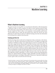
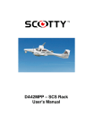
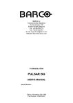
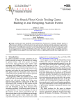
Figure 1 shows a schematic representation of our system layout. Our aircraft is an 83 in
wingspan custom-made foam delta-wing airframe. It is powered by a 24 V AXI brushless
motor and carries a payload of up to 14 lbs, including the autopilot systems, a gimbaled
camera, a Ham band video transmitter, and batteries. There are two channels of communication: the data and control line, a 900 MHz serial modem connection; and the video feed
transmitted on UHF channel 58. The ground station computer, which receives data from the
plane and controls its operations, also runs a telnet server, enabling networked computers
to access the plane’s data.
Figure 1: System Overview
CUAir: Cornell University Unmanned Aerial Vehicle Team
5
3
3.1
Mechanical Systems
Airframe
This year CUAir continued its development of a delta wing UAV. The plane is still made up
of two types of foam: a sturdy foam for the body and a softer foam for the leading edge.The
nose of the aircraft now has a composite fiberclass cover. Reenforcing this section of the
leading edge shifts the center of gravity farther forward and protects the foam from sharp
objects on landing. The original goal for this year to was make the entire frame out of a
shell of fiberglass, allowing all components to sit inside the plane. Unfortunately in order
to make the fiberglass thick enough so that it did not warp in flight the shell would be too
heavy.
By using a glider design the aircraft is able to acheive a stall speed of approximately
20 ms while fully laden. The fully loaded airframe weighs less than it did last year, due to
a selection of lighter electrical components and cutting down on the number of systems on
board.
The foam construction also makes our aircraft extremely resilient. The wing is able to
land on nearly any surface, making runways unnecessary. Looking ahead to future military
applications, this feature is essential for a craft of this size and range. The only two control
surfaces are the elevons on the trailing edges of the wings. Carbon shafts and strips along the
span ensure that no warping occurs, and the design is incredibly stable and free of buffeting at
high speed. The foam also helps to dampen any vibrations, resulting in precision navigational
readings not found on other planes. With so many advantages, we see our airframe as the
start of a revolution in UAVs.
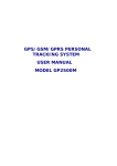
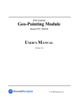
3.2
Canopy
Since cutting many holes in the
foam wing would damage its
structural integrity, the electri
components are bolted securely to
the top of the plane (the single exception being the gimballed camera.) A thin layer of plywood is
epoxied to center section of the
plane to give the components a
sturdy surface to be secured to.
A fiberglass canopy, formed over
a foam mold, is used to protect
the electronics during flight.
Figure 2: The Airframe with Canopy
The canopy was designed to
maintain the center of gravity and
give the plane the most stability. A foam mold was built by gluing cross sections together.
The mold was then covered with packaging tape, which would allow the fiberglass to peel
off easily. Then four layers of lightweight fiberglass were applied with epoxy.
CUAir: Cornell University Unmanned Aerial Vehicle Team
6
This year’s canopy is more flexible and narrower than the canopy used last year. By
reducing the size and number of electrical components the canopy was able to be reduced
in size. This reduction in size reduces drag from the canopy and improves airflow over the
motor which is at the rear of the canopy. The flexibility of the canopy is important: in a
crash, instead of the canopy cracking and allowing components to be damaged, it flexes and
absorbs the impact.
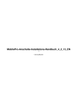
3.3
Motor
The CUAir UAV is still driven by an AXI 4130/16 model electric motor with a 16x8 in prop, powered by two 3 cell lithium
polymer batteries in series. This motor was chosen last year
because it produces a lot of thrust while the plane is climbing
or moving at high speed, yet is still efficient at low speeds.
The use of an electric motor over a gas motor gives the
plane more flexibility. An electric motor is lighter, and the
batteries can be placed anywhere in the plane to move the
center of gravity. While charging batteries between flights Figure 3: A close-up of the
takes longer than simply refueling an engine, with a charge motor
time of one hour and the a maximum flight duration of two,
simply having two sets of batteries can keep the plane continuously flying with short landings
every hour and a half.
3.4
Launcher
Based on positive past experiences, the team decided to keep the assisted launch system
first demonstrated at the 2005 competition. This system uses an electric winch and launch
ramp setup. The launch ramp is primarily made of one-inch diameter PVC piping and PVC
couplings, with the top surface being made of slightly larger diameter pipes to provide a
smooth take-off surface between the pipes and couplings. The two launch rails consist of
smooth PVC pipe about 6 ft long. The ramp is angled upward, so during takeoff the plane
has a positive angle of attack.
As the plane sits on the ramp awaiting take-off, the electric winch is set up alongside
the launcher. This is a superskeg supplied starter motor, powered by an external 12 V car
battery. When powered, this winch reels in a spool of nylon winch line which has been feed
through a turnaround pulley and then to a ring and hook mechanism on the plane. This
mechanism consists of a “launch-hook” which is attached to the plane and a ring attached
to the winch line. The hook is swept back and is secured to the underside of the aircraft
three inches forward of the CG. The location of the launch hook was found through many
iterations of trial and error. If the hook is too far forward, it will pull the nose of the plane
down during takeoff negating any positive lift created, whereas if it is too far aft, it will be
pulling from behind the center of gravity causing an unstable launch and even a stall of the
plane.
Once the launch hook is properly attached, the ring is placed in the hook. When the
winch is powered on, it accelerates the plane up to a rollout speed of 15 ms over a period
CUAir: Cornell University Unmanned Aerial Vehicle Team
7
of 2-4 seconds. The ring falls off the hook either when the plane is over the pulley or when
the winch is switched off. By using an externally powered launch mechanism we are able to
extend flight time because no on board power is used to launch the plane.
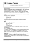
Another advantage that this launch mechanism has over a conventional runway is that the
plane does not require a smooth surface to take
off from. The winch and pulley can be staked
or weighted down on any sort of ground. The
plane is also accelerated up to speed faster than
a conventional fixed wing aircraft and can thus
gain altitude quicker. These advantages give the
plane terrain flexibility over conventional take
offs, making this design more versatile. It is possible to launch the aircraft from rocky ground
using this system, and land it elsewhere for recovery. The launch ramp is collapsible into 3
sections. The sections of the PVC pipe that
make up each section are strung together like
tent poles. This makes set up extremely streamFigure 4: Fully Assembled Launcher
lined and can be done by a single individual.
4
4.1
Electrical Systems
Kestrel Autopilot
Because of the requirement for UAVs to be fully autonomous without any assistance from
the ground, CUAir sought to find the most flexible and operable autopilot system available
on the commercial market for their UAV. Last year, CUAir utilized the MicroPilot autopilot
platform to control the UAV aircraft. However, in using this platform the team ran into
numerous difficulties in obtaining reliable performance from the autopilot which greatly
affected their performance during the summer AUVSI UAV competition.
The Kestrel Autopilot System developed by Procerus Technologies presented itself as
an effective and robust platform upon which to build the team’s UAV around. One of
the most striking aspects was its significant size advantage in that it only weighed 16.65 g
with dimensions at 2x1.37x.47 in. These dimensions include the autopilot’s modem used for
communication to the ground station, a large improvement over the bulky external modem
required by the MicroPilot in the previous year. Such space improvements are significant
because they in turn allow greater flexibility in the payload distribution on an aircraft where
every pound makes a difference.
By incorporating a complete gamut of sensors including a magnetometer, 3 temperature,
and 2 air pressure sensors in addition to the usual measurement of the 6 degrees of freedom
of an aircraft, the Kestrel provides the user with a great deal of accuracy in reflecting the
state of the aircraft. The magnetometer is utilized to aid in providing readings for aircraft
heading during low-speeds or when the aircraft is stationary and is unable to obtain heading
CUAir: Cornell University Unmanned Aerial Vehicle Team
8
information from the external GPS unit. The 3 temperature sensors on the aircraft are used
in conjunction with a compensation algorithm in order to reduce the need to re-calibrate
gyros or pressure sensors because of the effect of temperature variation on the readings.
The air pressure sensors reflect both barometric pressure of the aircraft at its flying altitude
as well as airspeed. Combined with GPS information, the Kestrel is also able to use this
information to provide an estimate on wind speed and heading, accurate to 5% and 2%
respectively. With these sensors the Kestrel provides information at a level unmatched by
the MicroPilot.
Another advantage the Kestrel provides is
built-in support for an onboard camera gimbal
system. This is crucial because it allows full user
control over the video camera that is mounted
on the underside of the aircraft. Through the
ground station the user is able to manually manipulate the camera via joystick. The Kestrel
also has the ability to stabilize a gimbaled camera. By adjusting the servo bias and the scalars
any sort of payload that incorporates two servos
for stabilization can be calibrated.
Flexibility of operation is another defining
Figure 5: The Kestrel 2.2 Autopilot
aspect for the Kestrel. Its power consumption
is regulated only to its requirements, extending
battery life. In addition, the Kestrel provides the user with real-time battery life information
along with a variety of other information and tools in Procerus’s proprietary Virtual Cockpit
ground control software. In addition to its 4 servo ports, the Kestrel also is able to support
another 2 servos for aircraft operation through an external servo board. This external servo
board is used by CUAir to control the camera gimbal.
The Kestrel communicates to the ground via a pair of 900 MHz modems, one connected
via a header to the Kestrel, and the other housed in the Commbox on the ground. The
Kestrel is designed to work with the Aerocomm AC4490-1000 modem. Because the autopilot
is designed to work with this modem there are minimal compatibility issues. The modems
broadcast at 1000 mW and has been tested up to a range of 10 km in open air with line of
sight with minimal packet loss. With this range the aircraft is far out of sight before any
loss of communication can be expected.
There are numerous fail-safe settings that will engage the aircraft in predefined actions
should the Kestrel face undesirable situations such as loss of communication. The situations
that have defined fail-safe responses are:
• loss of GPS for a specified period of time
• loss of communication to the ground for a specified period of time
• low battery voltage
For each of these scenarios the user can set up two values for which the Kestrel will perform
different actions. For example, the user can set the fail-safe so if the battery level drops
CUAir: Cornell University Unmanned Aerial Vehicle Team
9
below 10 V the plane starts on a flight path toward the home GPS coordinate, which is
predefined at the beginning of each flight. Once the battery level drops below an even lower
user specified point, the plane will bring itself down immediately to prevent shutting down
while throttle is still on. Any problems that are encountered can be fully examined through
Virtual Cockpit’s integrated data logging.
Through Virtual Cockpit, the aircraft can also be told to engage in several predefined
“modes”, which include holding speed or altitude, flying home, or loitering around a waypoint. The aircraft can also be told to engage in convoy following mode if a GPS unit is
hooked up with the commbox to provide a constantly updated (if moving) “home” position
for the aircraft to follow. If so desired, Virtual Cockpit also has the power to manage multiple
UAVs simultaneously through one ground station.
With amount of control and functionality offered, CUAir is confident that the Kestrel
and its supporting software Virtual Cockpit will fully serve their needs in developing a
competition-ready aircraft.
4.2
Ground Station
One major addition that CUAir added to this
year’s model is an all encompassing ground station. This system consists of the Commbox v1.1
from Procerus, a Compaq Presario v2000 laptop, a RAM laptop mount, a USB-to-serial converter, a 900 MHz antenna, and a plastic case
that houses everything. The Commbox is made
by Procerus and houses the Aerocomm Modem
and the hardware interface to a serial connection. The serial connection gets passed through
an off the shelf USB-to-serial converter, which
is then plugged into a USB port on the laptop.
The laptop itself is securely mounted to the inside of the Platt case by a RAM Tough Tray
Universal Laptop Mount. We chose the Compaq Presario v2000 laptop for its economic pricing as well as its compact size. With a screen Figure 6: The All-in-One Groundstation
of only 14 in. the laptop is small enough to be
housed in the case along with all the other necessary components. The Platt case itself,
model 1419, is made of ABS plastic and measures 18 in wide by 13 in deep by 5 in high.
The mounting hardware for the 900 MHz antenna is attached to the outside of the case.
The antenna is made by Nearson, model number SG101N-915, and was chosen for this
application on the recommendation of Nearson for its operation gain of 5 dB and VSWR
of less than 2.0 which is adequate for our frequency range and power. We found through
testing that we received more data packets per second using this antenna over the stock 900
MHz antenna that came with the Commbox.
After a little training a user can set up and power up the ground station in less than five
minutes.
CUAir: Cornell University Unmanned Aerial Vehicle Team
10
4.3
Camera
To capture the image while the vehicle is in flight, a CCD
board camera was chosen rather than a CMOS camera because, in general, a CCD camera give better image resolution
with less noise than a CMOS image sensor. A black and white
camera was chosen over a color CCD camera, because the vision algorithms discussed use only the brightness information,
and a color camera with the same stated resolution as a black
and white camera will filter out more light and have a lower
resolution brightness channel. A lens camera was selected over
a pinhole camera, because a lens camera does not need as fast
an exposure time, collects more light, and provides a more de- Figure 7: The EverFocus
tailed image. This is ideal for a fast-moving plane. A camera CCD Camera
with a low illumination factor so useable imagery can be collected under adverse weather conditions. The Ever Focus EB110E4 was chosen bevcause it
fit all of these criteria, and included the auto gain control attribute, which increases camera
performance in low light conditions. The camera is also composed of an electronic shutter,
which can stop a moving image to about 10 µs. Under varying light conditions, this cameras
lens iris with the shutter lets in the optimal amount of light for a crisp image. The 4.3 mm
lens covers a range of 58 horizontally and 45 vertically. The chosen camera also uses a 12 V
power supply, which can be connected to any other 12 V battery that are already present on
the plane, such as the one powering the Kestrel autopilot.
4.4
Video Transmitter
The image received by the CCD camera is transmitted to a video receiver on channel 58
using a TV transmitter. PC Electronics’ TXA5-RCb ATV TRANSMITTER BOARD was
used to broadcast the received from image from the camera. In order to stay away from FM
and ATV repeater inputs, the transmission frequency used is 426.25 MHz. There is a crystal
controlled oscillator around 106 MHz, which is 1/4 of the output frequency. The frequency
range is 425 to 440 MHz with a crystal tolerance of 0.005%. A stable power source of 12 V
will be used to power the transmitter. The power source should be stable as any ripple on
the supply voltage can show up as noise in the video. An RCA video jack is used to connect
the camera to the transmitter. This transmitter has been tested and is good for up to 5
miles. The description of the transmitter antenna is detailed in another section.
The video is recieved on the ground by a WinTVToGo PCI card installed on a PC. The
card has various input options, one of which is for an external antenna, eliminating the need
for any extra external hardware. The card also uses standard windows drivers so that the
signal can be easily used by other programs. The Shuttle PC runs the vision processing
algorithms written by the team to process the frames of video and stitch together an aerial
map.
CUAir: Cornell University Unmanned Aerial Vehicle Team
11
4.5
Power System
The aircraft is powered by several Lithium Polymer model airplane batteries purchased from
Tower Hobbies. There are two 12 V batteies made by Thunder Power. Each battery is three
cells and 8000 mWhr. The batteries are connected in series to power the 24 V AXI motor.
There is one 12 V three cell battery made by Kokam that is used to power all of the on board
electrical systems. All on board systems were chosen to fit this 12 V power supply so that
there would be no need for voltage regulators which consume power. This single battery is
capable of powering all the systems for longer than the motor batteries can power the motor.
This gives a window during which the motor can lose power but the aircraft is still capable
of landing itself. The aircraft can stay aloft for close to 2 hrs on a single charge flying at
cruise speeds.
4.6
Aircraft Tracker
In order properly document our test flight a video camera is used. However, the accuracy
of this footage is seriously impeded upon by the skill of the cameraman (i.e. loosing sight
of the plane or an unsteady shot of the plane). Hence the implementation of a ground
tracking station fundamentally eliminates the human error and improves the quality of our
documentation.
The ground tracking station consists of three components: The Pan-Tilt Module, The
Geo-Pointing Module, and the host computer. The Pan-Tilt Module (PTU) is simply two
orthogonally connected servos mounted atop of a tripod. This set up allows the “load” (i.e.
the camera) to have two degrees of freedom. The PTUs pan range is approximately +/159 degrees (318 degree range) and its tilt range is 31 degrees up and 47 degrees down (78
degree). Its angular resolution is 0.771 arc minutes (0.012857 degrees). This makes for a
cone shaped “blind spot” in the field of view, with its pinnacle located at the camera and
its base radiating above and below it. Since the object of interest will be flying overhead
the lower limitation becomes inconsequential. The upper limitation on the other hand is
of slight concern, but because the plane is moving at a high speed even if it were to fly
directly overhead, the picture of the aircraft would only be lost for a matter of seconds. The
Geo-Pointing Module (GPM) is implemented on a Netburner Mod5282 microcontroller, and
uploaded via The Netburner Development C++ software. The program is stored in flash
so that it will not be lost each time the system looses power. The GPM allows the PTU
to point its “load” using latitude/longitude coordinates (GPS) instead of pan-tilt angles.
The GPM is communicated to via TCP/IP protocols allowing it to be controlled via a host
computer or over a network. For our application we use a single host computer, connected
via a Cat5 cross-over cable. The system can be controlled and calibrated manually via its
built in web page interface or by using HTTP commands in DPoIP command format. These
commands are in the following form:
http://<ipaddr>/<verb>?cmd==<command><params> or
http://<ipaddr>/<verb>?<command>=<params>
<ipaddr> is the IP Address of the GPM
<verb> ? { "non’’ , "raw’’ } The "raw’’ form returns the result from the command.
The "non’’ command executes the command but returns no data.
?cmd==<command><params> or ?<command>=<params>
<command> is a Geo-Pointing or Pan-Tilt command
CUAir: Cornell University Unmanned Aerial Vehicle Team
12
A list of these commands can be found in the GPM’s user manual
<params> are the appropriate parameters for the given command
In order to authenticate commands issued via DPoIP a HTTP Basic Authentication
Scheme is used. When issuing DPoIP commands to the Geo-Pointing Module from a browser,
the user will be prompted for a username and password. Only a valid username and password
will allow commands to be sent to the GPM. Calibration of the GPM is done using a built
in function that computes the orientation of the PTU in real-world coordinates (lon, lat,
alt) using a set of user provided landmarks along with the GPS coordinate of the PTU. To
do this a landmarks location is entered in the form of a GPS coordinate and the PTU is
then aimed at that landmark. This process is iterated four or more times and the GPM
updates the PTUs orientation estimate accordingly. Landmarks should be chosen so as to
cover a wide span of angles and distances, and although a minimum of four landmarks is
required additional landmarks can improve the GPMs pointing accuracy. Once calibrated,
the GPM is ready to accept streaming or manually entered commands and queries from the
host computer. The overall accuracy of the GPM is determined by the pointing resolution
which is defined during calibration. If during calibration several well spaced landmarks
are used and the PTU is carefully aimed at them, the angular accuracy of the GPM will
approach the angular resolution of the PTU. The host computer is the final component
in this system. It receives one GPS coordinate from the Procerus autopilot every second,
processes it via the telemetry server and forwards it to the GPM via TCP/IP protocols in
the above described DPoIP format in real time. Thus allowing the camera mounted atop of
the PTU to constantly be pointed at the aircraft.
5
5.1
Software Systems
Virtual Cockpit Control Software
The ground station runs Procerus’s Virtual Cockpit software.
This software interfaces with the Commbox through a serial
port to interface with the Kestrel autopilot device on the vehicle. It displays telemetry data from the plane, as well as communication and battery status of the Kestrel autopilot and the
Commbox. It allows for high-level mission management functionality as well as low-level access to PID coefficients and
other flight parameters.
The top left of the main window allows the user to set the
autonomous mode of the plane (which is active when the pilot
switches off channel 5.) The plane can be set to return home,
take off, land, maintain a certain speed, altitude or waypoint. Figure 8: Virtual Cockpit
Under the mode selection is the heads up display, with an Main Window
artificial horizon, some telemetry information, and communication and battery status for the Commbox and Kestrel.
The main part of the screen is a map showing the current location of the plan, the home,
landing, and approach waypoints, and the path of the plane since takeoff.
CUAir: Cornell University Unmanned Aerial Vehicle Team
13
The settings window is where all the low-level flight parameters are set. The PID loops active during each autonomous
mode, the actual PID coefficients, the payload settings (in our
case, the gimbaled camera.) The Virtual Cockpit software
also has a TCP/IP socket server that allows outside applications to access data and communicate with the autopilot.
This is used by CUAir’s Telemetry Server (see Section 5.3),
which allows client applications to subscribe to certain data
Figure 9: Virtual Cockpit points. Client applications include the mosaicking app and
the antenna tracker.
Settings Window
5.2
5.2.1
Vision Processing
Overview
The system that we’re implementing will present a bird’s-eye map after and during the flight.
The user will have to identify the targets manually from the image.
Features of the program include:
• Real-time mosaic map of the ground that is rendered as the plane flies.
• Each pixel of the mosaic will have its GPS coordinates figured out by the program;
this will assist in identifying the location of targets on the map.
Everything is handled inside one main class; the code footprint for this system is quite
small.
The algorithm that we’re using to glue together the images from the camera and put
together the map of the ground follows these steps:
1. Use OpenCV to identify key “features” of the current image that are easy to track.
Usually the algorithm will return around 10 to 20 points on the image.
2. Identify where the points from the last step are in the next image.
3. Calculate the transformation from the first image to the next.
4. Apply the transformation to the second image, and draw it on the main map. It will
be aligned to the previous image.
5. Repeat.
What we will also do is use the plane’s current GPS location each frame to get a rough
estimate of the GPS location of each pixel in the frame, so when we identify targets we will
also have a GPS location for them.
CUAir: Cornell University Unmanned Aerial Vehicle Team
14
5.2.2
Program
This section will walk through the major sections of the code and explain what each peice
does.
numCorners = 50;
cvGoodFeaturesToTrack( lastYImage, eigImage, tempImage, lastcorners, &numCorners,
/*quality_leve*/.3,
/*min_distance*/15.0,
/*mask*/
NULL,
/*block_size*/
3,
/*use_harris*/
0,
/*k*/
0.04 );
This code accomplishes the first step given in the algorithm above. The function takes
in the last image that we have, along with a few other parameters, and fills the array
lastcorners with the features to track across frames. We also do a quality check right after
this; if we don’t have N features to track (where N is about 15 for our purposes), then we’ll
just abort this frame and try again when the next frame comes.
cvCalcOpticalFlowPyrLK(lastYImage, YImage,
/*prev_pyr*/NULL,
/*curr_pyr*/NULL,
lastcorners, corners, numCorners, cvSize(10,10),
/*level*/4
,LKstatus,
/*track_error*/NULL,
cvTermCriteria(CV_TERMCRIT_ITER,10,.05),
/*flags*/0);
This function takes in both images (the one used in the previous function call and the
new image), and calculates where the feature points from the last image went in this frame,
and stores the resulting points in corners.
Next the program does a little linear algebra with the resulting lastcorners and corners
arrays. A 2-d transformation of an image can be expressed as:
Ax‘ + By‘ + C = x
Dx‘ + Ey‘ + F = y
(1)
(2)
where (x, y) and (x‘, y‘) are the coordinates of a pixel in the previous and current frames,
respectively. We want to use the features that we just picked out from both images so we
can figure out the coefficients A through F . We can use matrices to solve the system of
equations efficiently, by setting up the matrices in the following manner:
x‘
A B C
x
y‘ = D E F y
1
0 0 1
1
The program fills the previous points and next points matrix, then uses OpenCV to solve
for the coefficients matrix. It then uses the coefficients to transform the current transform
matrix:
composeAffineTransform(curTrans,cumuTrans);
Then the program uses this transformation to draw the current frame into the right place
on the map:
cvWarpAffine(frame,mosImg,cumuTrans,0,cvScalar(255,0,0));
cvShowImage(WIN_TITLE,mosImg);
CUAir: Cornell University Unmanned Aerial Vehicle Team
15
5.3
Teleserver
Procerus provides an API to Virtual Cockpit (VC) and allows third party programs to direct
interact with VC, the Commbox, and the Kestrel. However, VC cannot handle more than
one client connection at a time. In order to allow multiple applications to interact with the
aircraft system, we wrote a telemetry server that mediates the communication to and from
VC and other applications.
5.3.1
Overview
The telemetry server basically functions as a data bus and repeater, and as an unauthoritative
data server. Several features of telemetry server:
• allow other third-party programs to use VC’s API transparently, functioning as a data
bus.
• relay VC’s broadcast packets to all connected clients, functioning as a repeater.
• cache data contained within packets that pass through, especially from packets that
are periodically sent by VC, allowing clients to asynchronously request for information.
• ability to implement a simple protocols for specialized clients that require only certain
types of transactions.
• ability to create modules to perform pre-programmed macros or reproduce commands
that would otherwise be tedious using the VC GUI.
5.3.2
Design and Implementation
Simply, the telemetry server is a program that uses Procerus’ API to connect to VC and
listens for connections from other clients. In more detail than it was above, we wanted it to:
• listen on the connection to VC, and, for every packet not destined for any single entity,
log and broadcast the packet to all connected clients.
• listen on the connections to clients, and, for every packet not destined for the server,
log and relay to VC.
• accept and report on commands to the standard input/output streams of the controlling console. That way, operators can still interface with the server and change its
behavior on the run.
Those operations don’t make our telemetry server any more different, in function, from
a dynamically configurable relay. We also defined that our server should be able to function
as a recording and playback device to client programs. Thus, it must be able to:
• log any packet going through any part of the data flow to a file.
CUAir: Cornell University Unmanned Aerial Vehicle Team
16
• playback logfiles for client programs simulation and testing without having to be flying
out on the field.
• playback logfiles for client programs that have non-realtime algorithms (e.g. postprocessing) that require a sequence of valid telemetry data. These instances could
make use of a specialized protocol extension other than VC API.
Of course, we wanted to keep our software as platform-independent as possible without
resorting to using byte-code interpreted languages like Java or .NET. We chose to use C++,
and along with that, we incorporated the Apache Portable Runtime library to handle the
platform-dependent interface to platform-dependent operations - e.g. file IO, sockets, memory allocation, concurrency control, network IO. As an extra, we were able to make use of
APR’s memory pools as a foundation for a simple managed memory solution.
The extensibility of additional clients and processing modules is modeled after modern
windowing systems’ event handling. Like when an object wants to be notified when an
event occurs, a client object that wants to receive all non-directed VC packets adds a reference to itself to an array, provided it supports the common void VCPacketArrived(struct
VCPacket *) method.
The distinguished classes that were implemented are:
• VCsocket, which handles every VC communication-specific aspect of the transaction.
The implementation of the specified protocol lives here.
• CLparser, which parses the command line inputs into a command/operation struct
that contains all arguments.
• TSclient, which handles communications between the telemetry server and the clients.
• Logger, which is a uniform logging solution that’s integrated into all the other classes of
the suite. Where a class has incoming data from a network socket, a Logger-compatible
interface is also supported. This way, logged packets can be replayed at the current
times.
CLparser is implemented so the use of CLparser is like using a bison/yacc solution.
Bison/yacc would have been used, but the project is currently being compiled using both
GNU GCC and MSVS .NET 2003, which would require extra work to keep Win32 APIcompatible bison/yacc binaries, short of installing Cygwin.
TSclient and VCsocket make heavy use of APR’s network IO routines, and thus mostly
functions as a wrapper to any sort of networking-specific code.
Logger relies on APR’s file IO routines. However, since APR does not yet have a builtin logging functionality, Logger implements both persistent and non-persistent file logging
models, which takes into account the undesired lag possibly present when used in a realtime
application.
At the moment, caching of variable data is done by the server as local variables, and
has not been generalized to a class. When the server has been extended to be able to route
among several VC upstream connections, a class for caching telemetry data would be made
worthwhile implementing.
CUAir: Cornell University Unmanned Aerial Vehicle Team
17
5.3.3
Client Interaction with the Telemetry Server
To date, the TSclient class in the server implements three types of protocol transactions:
1. clients wishing to communicate using only the VC API, e.g., clients in transparent
operation to VC.
2. clients wishing to communicate with the server using a specialized protocol, e.g., to
take advantage of server’s variable caching.
3. clients wishing to communicate using both protocols.
TSclient assumes, by default, that all clients are communicating transparently (1). If
the client wishes to change the mode of communication, it must make it known in the first
packet sent to the server. If the second mode is requested, further communication will
continue in the defined protocol. If the hybrid mode is requested, the combined protocol
requires the first 8 bits of a packet to be an int, which is the index of the protocol: 1 for a
VC packet destined for the VC uplink, 2 for a packet for the server.
Since VC supports attaching an identifying number to individual requests, which it appends at the end of every response, the server keeps a table to map request numbers specified
by a TSclient to ones it chooses to send to VC. Thus, when VC responds with the mapped
request number, the server knows which TSclient it belongs to. This behavior is very much
like NAT’s, where the remapping of source and destination in the IP headers of a mangled
packets must be restored by the NAT gateway before final delivery to the requesting client.
6
Conclusion
CUAir’s entry to the 2005 AUVSI Student UAV Competition is one of the most innovative
and successful UAV’s to be designed for several reasons. The unique foam delta-wing airframe
makes this design economically appealing, while still being easy to use for even an untrained
pilot. When this is combined with an all-in-one, ultra-portable groundstation, it is the most
functional platform available.
Having the design centered around ultra-robust components, especially the Kestrel autopilot, ensures that minimal failures will occur. We have also invested much time into
creating valuable software systems, including our mosaic-ing application, which make identifying ground targets as easy as possible. We believe this entry will be extremely successful,
and even cause a revolution in future small-scale UAV design.
7
Appendix I: Flight Checklist
1. Prepare launcher and winch
2. Prepare and power on Groundstation
3. Power on plane electronics, except motor
CUAir: Cornell University Unmanned Aerial Vehicle Team
18
4. Power TV or Vision Groundstation and verify connections
5. Perform range test of plane to groundstation, verify GPS lock
6. Validate all control surfaces respond correctly
7. Verify pilot is able to put plane in and out of autopilot mode safely
8. Perform autopilot self-test on all sensors and reactions
9. Have one person supply power to plane while holding it on launcher for throttle test
10. Safely secure canopy to plane
11. Begin Countdown and Takeoff
Upon landing
1. Remove canopy and remove power to throttle
2. Retrieve data logs and download any other pertinent information from Kestrel
3. Perform any post processing on vision station
4. Power down autopilot and plane electronic systems
5. Break down launcher and Groundstation at end of last test flight
8
Appendix II: Safety Report
8.1
General Safety Rules
• All people at a test flight operating equipment or near the aircraft are required to wear
safety glasses at all times.
• Use of any power tools or other dangerous materials should be accompanied by proper
personal safety protection, such as goggles, gloves, aprons, closed toed shoes, etc.
• While not in use all batteries, LiPoly, NiCd, and others, are to be kept in the fire safe
in the lab.
• At all times while batteries are being charged they are to be clear of any combustable
material and kept under constant observation.
• Prior to powering the throttle on the aircraft varify all areas around the plane are clear
and that no one is in the plane of the propeller or behind.
• Prior to flight all bolts and components on the aircraft are to be checked to make sure
they are secure and will not become detached.
• If at any time the plane becomes unstable and the pilot cannot control it manually, it
is to be brought down as quickly as possible in an open area clear of people.
CUAir: Cornell University Unmanned Aerial Vehicle Team
19
8.2
Fail-safe Procedures
Event
Description
Rate
Mode
Failsafe
Rate
Mode
Failsafe 2
Loss of Comm
Autopilot does not receive
RC packets
Autopilot does not receive
RC packets
Communication
with
Groundstation lost
Loss of GPS
Lock
Loss of GPS
Lock 2
Low Battery
GPS lock is lost in autopilot
mode
GPS lock is lost in autopilot
mode
Main Battery Voltage drops
below 10 V
Main Battery Voltage drops
below 9.5 V
Critically Low
Battery
9
Time
Behavior
Elapsed
>1.5 s Fly Level
>5 s
Fly Home
>2 s
Perform Competition Failsafe (i.e. Throttle closed,
full up elevator, full right
aileron)
>5 sec Perform a shallow bank of
15 ◦
>15 sec Land plane immediately
any
Fly to Home GPS position
any
Land plane immediately
Acknowledgment
CUAir would like to thank the following groups and individuals. Without their support,
none of this would have been possible:
• Cornell University
• Procerus Technologies
• Our advisors Professors John Belina and Charlie Seyler
• Our friends and parents for their support
CUAir: Cornell University Unmanned Aerial Vehicle Team
20