1
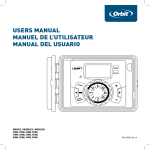
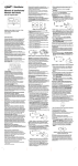
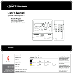
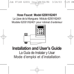
n Installation Manual / User’s Manual Insert two AA batteries into the battery compartment (batteries not included). n Return the terminal cover to its closed position. Remove batteries when depleted or if product is to be left unused for a long time. The program will be retained for up to 30 seconds while the batteries are replaced. Do not mix old and new batteries. Do not mix alkaline, standard (carbon - zinc), or rechargeable (nickel cadmium) batteries. Weak or missing batteries can cause the time and date to be erased after a power failure. n n To skip a station, press the next key. To erase previously programmed watering durations, press the clear key. Assigning Watering Days for Program A n Turn the rotary dial to day of week in program A. The display will show an “A” and the cursor will blink under the days of week Monday, Tuesday, Wednesday, etc. [See Figure 6]. Set the Time of Day and Date If this is the first time the timer has been programmed, you should press the small recessed button labeled reset. Pressing reset does not affect the factory installed fail-safe program [See Figure 2]. Figure 6: LCD Display with Watering Days Press enter to activate watering on Monday. An arrow appears under M and the cursor will advance to Tuesday (T), press enter to activate watering on this day. Repeat these steps for all days of the week. n To skip a day, press next. n To delete a previously entered day, press clear n If you want to water every second day, press the next key to advance the cursor to “2nd”, then press enter. Note: If you choose to water every 2nd day, you cannot set specific days of the week for watering n Figure 2: Programming Keys n n Models: 27954, 27956, 57114, 57161, 57162, 91046, 91054, 94122, 94124, 94126 n WT2X Version n Introduction n Thank you for selecting an Orbit® sprinkler timer. Orbit® designers have combined the simplicity of mechanical switches with the accuracy of digital electronics to give you a timer that is both easy to program and extremely versatile. The Orbit® timer provides convenience and flexibility, letting you run a fully automatic, semi-automatic, or a manual watering program for all your watering needs. Please read this manual completely before you begin to program and use the controller. A few of the most notable design features include: At-a-Glance Simplicity By turning the rotary dial to one of nine settings you can review programming or easily make changes. Arm Chair Programmable By inserting two AA alkaline batteries you can program the timer prior to installing it in its permanent location. Fuse The 0.75 amp slow-blow fuse provides circuit protection. For replacement, use WaterMaster 0.75 amp fuse or equivalent. Lexan Language Covers Available in English, French, Spanish, Italian, and German. 1. Digital Display A large LCD (Liquid Crystal Display) shows the time of day and indicates many of the programming settings. The display is completely interactive with all other controls. 2. Programming Keys The timer has seven push button keys for setup and program entry. Working in conjunction with the rotary selector, the keys are used to set the time of day, watering time, watering days, start times, and other functions. 3. Selector Dial This large dial makes it easy to see which function is currently selected and/or in which mode the timer is set to operate. 4. Reset Button The reset button clears the time, date, and user-defined programming, but does not remove the factory installed fail-safe program. To prevent an accidental reset, the button is recessed into the panel and must be pressed with a small pointed object such as a pen or pencil tip. 1 3 4 2 FIGURE 1: Location of Controls on the Timer Notable Programming Features Two Watering Programs—Summary The timer gives you the option of using one or both of the independent programs. Note that each station can independently be set to either A or B or both A and B programs. Program A This program lets you schedule selected stations to water on specific days of the week or to water every 2nd day. Program A repeats itself continuously in successive weeks. Program B Provides two options: One for odd or even day watering or for intervals ranging from everyday to every 28th day. This feature is designed to meet the growing needs and restrictions imposed by local governments and to conserve water. The timer automatically calculates odd and even days (by date) for each month and makes adjustments for leap years to provide true odd and even watering through the year 2100. Start-Time Stacking The timer has the intelligence to “stack” start times that overlap. If you enter two or more start times that overlap (in the same or in different programs), the timer will not activate two stations at the same time. Instead, the timer activates the first station and then activates the next station(s) in sequence after the first station finishes its preset watering duration. The timer will NOT stack to the next calendar , preventing the timer from violating an odd or even day watering schedule. Manual and Semi-Automatic Modes The timer gives you a number of manual and semiautomatic modes for flexibility in watering. You can override the timer’s automatic programming in a variety of ways. n n Turn the rotary dial to the time/date position [See Figure 3]. 12:00 AM will appear in the display with three arrows pointing to the year, month, and day. Use the + and - keys to set the correct time of day. When the correct time of day is reached, press the ENTER key to lock in the time. To increase or decrease more rapidly, hold down either the + or – keys until the display goes into rapid advance mode. A blinking cursor will appear below the arrow for the year, month, and date when programming [See Figure 3]. Use the + and – keys to set the correct year, then press ENTER. Use the + and – keys to set the correct month, then press ENTER. Use the + and – keys to set the correct date, then press ENTER. Assigning Watering Intervals for Program B Program B is used to water at specific intervals between days (1 to 28), or on odd or even calender dates. The timer has a leap-year compensator and will ensure conformance to the odd and even schedule through the year 2100. n Turn the rotary dial to watering interval. The cursor will blink to the left of the word interval [See Figure 7]. 5:00 Figure 7: LCD Display with Watering Interval Figure 3: LCD Display with Surrounding Information Caution: If a watering schedule is not entered into the timer, the factory installed fail-safe program will turn on each station every day for 10 minutes. To avoid accidental valve activation, either turn the rotary dial to OFF or enter a watering schedule. Establish a Watering Schedule To help you visualize how best to program the timer, it might be helpful to make a watering plan on paper. This will help you establish which days and times you want to water. Programming The timer has two programs you can set up to control a variety of watering schedules. Depending on your needs, you can use either or both programs. Enter Watering Schedule in Any Order You have the option of entering your watering schedule in whatever order you like. This feature makes it very easy to review and change your watering schedule. Your settings can be changed at any time while you’re setting up the initial schedule or even after years of operation. Start Times for Program A or B Note: A start time is the time of day that the program begins watering the first station, and all other stations in the program will then follow in sequence. There are not separate start times for each station. Start times do not correspond to specific stations, but to programs (A or B). If you enter more than one start time, all stations in the specified program will water again (in sequence). n The way you set the cycle start time is the same for both programs. Turn the rotary dial to the cycle start times position in the program that you want to set. The display will show an A or B depending on which program you have selected. The display will show —— : —— and a blinking cursor in cycle start 1 location [See Figure 4]. n Set the time you want to begin watering for start time 1 using the + or – keys, then press the enter key. The display will advance to start 2. For additional start times, simply repeat this procedure by using the + and – keys to enter the time and then press enter. Remember, Each start time will activate all stations that are set to water in the specified program. There are not separate start times for each station. Start times do not correspond to specific stations. n Up to four start times can be entered per program (A or B). Press and hold the + or - keys to select the number of days between watering. Example: If you want to water once every 10 days, set the interval at 10. n To activate the watering interval, press enter. Note: If an interval of 3 is entered today, the timer will water for the first time today, and then again every 3 days. n To select odd or even day watering, press next. The cursor will move to either the odd or even setting, then press enter. n To erase a schedule, press clear. To enter a new schedule, press next. n Reviewing and Changing Your Program The Orbit timer lets you easily review a complete watering plan. For example, to review Program A watering start times, simply turn the rotary dial to the cycle start times position in Program A and check the times that have been entered. Using the next key, you can advance through the schedule without fear of disturbing any programming. If you want to change the start times, watering days, or interval, simply follow the directions for that program. After reviewing or changing a watering schedule, remember to turn the rotary dial back to auto. Ready for Automatic Operation After programming is complete, turn the rotary dial to auto [See Figure 8]. The timer is now fully programmed and ready to use in the automatic mode. In automatic mode, each program will operate sequentially, starting with Program A Figure 8: Ready for Automatic Operation Semi-Automatic & Manual Operation The Orbit timer has the ability to override the automatic program without disturbing the preset program. Using the Semi-Automatic Mode (All stations cycle once both A & B programs) n Turn the rotary dial to auto, then press the manual key. The display will show AB, MANUAL, and ALL will be blinking [See Figure 9]. This indicates all stations will semi-automatically water for their assigned durations in sequence. n To activate the assigned water durations in the A and B programs for each station, press enter. Figure 4: LCD Display with Start Time Figure 9: Semi-Automatic Watering for Stations Assigned to A and B Programs Water Duration for Program A or B Note: Both programs require watering durations to be programmed. n Turn the rotary dial to Station duration position in either the A or B program. The display will show which program you have selected with an “A” or “B” and the - - cursor blinking at station “1” [See Figure 5]. Note: Water durations assigned to station 1 in program A will water first, then move to station 1 in program B before advancing to the second station and will continue alternating. Only those stations assigned a watering duration will water when using the manual or semiautomatic mode [See Figure 10]. Getting Started Programming the timer can be accomplished in just a few basic steps. Before you begin programming, it is important to install the batteries (batteries not included), set the time of day and date, and establish a watering plan. Install the Batteries The timer requires two AA batteries to maintain the time, date, and programs in case of AC power loss. In a typical installation, fully charged batteries should provide sufficient power for approximately three years of operation. n Remove the terminal cover. Figure 5: Station Duration for Program A n You can set the watering duration from 1 to 99 minutes. Press and hold the + key to advance the number of minutes, or use the - key to go in reverse, then press enter. When the minutes are set, “A” or “B” will appear over station 1 and the cursor will advance to station 2 and begin blinking. n Simply repeat these steps to set watering durations for all zones on this program Figure 10: Semi-Automatic Watering Entered for A and B Programs, All Stations (All stations cycle once, A program only) To activate stations assigned watering duration for the A program only, press the manual key, followed by the next key. This will activate stations with assigned watering durations in the A program only. To initiate this semi-automatic watering, press enter [See Figure 11]. n 3. Connecting the Transformer n With the wiring terminal shroud off, find the two terminal holes labeled 24-VAC. Make sure the transformer is not plugged in. Insert one of the two power leads from the transformer into each terminal. It doesn’t matter which lead goes into which terminal. This power unit is intended to be correctly orientated in a vertical or floor mount position. 2 2000 n It may be necessary to1 6open the terminal to allow 1 200 for wire insertion or removal. To do this, turn the screw with a Phillips screwdriver until wire is secure [See Figure 16]. n Plug in the transformer Warning: Do not link two or more controllers together with one transformer. n Slide the shroud back on. B C Figure 11: Manual Watering in Either the A or B Program Only STATION DAY PROGRAM MONTH A YEAR NEXT B/C INTERVAL DAY M T W T F S S M T W T F S S A WEEK 1 WEEK 2 (All stations cycle once, B program only) n To activate stations assigned watering durations for the B program only, press the manual key, followed by pressing the next key two distinct times. This will activate only those stations with assigned watering durations in the B program only. To initiate this semi-automatic watering, press enter. NEXT CLEAR MANUAL + – ZONE 1 ENTER 2 3 SET WATERING DAYS WATERING DAYS We OFF C AUTO RESET RAIN DELAY DIAG. REVIEW 5 6 7 8 9 10 OFF 11 MANUAL ON WATERING DURATION MINUTE B SET TIME AND/DATE RADIO TIME 4 SET START TIME 2 5 10 15 20 25 30 45 60 120 12 MASTER VALVE BUDGETING % 200 175 150 125 110 NORMAL 90 75 50 25 MANUAL OFF PROGRAM A B C Control Center COM 1 2 3 4 5 6 PUMP 24V 24V Using Manual Operation The manual operation mode allows you to set durations in any of the stations from 1 to 99 minutes. n Turn the rotary dial to auto. n Press the manual key. Then press next three times. The display will show a blinking cursor on station 1 along with - - MINS [See Figure 12]. FIGURE 16: Connecting Transformer Precautions: • This controller is not intended for use by young children or infirm persons without supervision. • Young children should be supervised to ensure they do not play with the controller. Figure 12: LCD Display with Manual Operation n To set the number of minutes for watering duration, press and hold the + key to advance to desired number of watering minutes. Use the - key to go in reverse. Press enter to begin watering. n To skip a station, press next until the cursor is blinking over the station number you wish to program. Example: To set station 3 for five minutes, press the manual key; then press the next key five times to select the manual operation mode and advance to watering for station 3; using the + or - key, set the manual watering duration to five minutes; then press enter [See Figure 13]. Figure 13: Manual Watering Station 3 for Five Minutes Installing Valves, Pump Start Relays & Master Valves 1. Wiring the Electric Valves n If the distance between the controller and valves is under 700 feet (210 m), use WaterMaster® sprinkler wire or 20 gauge (AWG) plastic jacketed thermostat wire to connect the controller to the valves. If the distance is over 700 feet (210 m), use 16 gauge (AWG) wire. Terminals accept up to 14 gauge wire. The wire can be buried in the ground; however, for more protection wires should be pulled through conduit and buried underground. Be careful to avoid burying the wires in locations where they could be damaged by digging or trenching in the future. n Each valve has two wires. One wire is to be connected as the common. The common wires for all the valves can be connected together to one common wire going to the timer. The other valve wire is to be connected to the specific station wire that will control that valve [See Figure 17]. Jacket Note: After the manual key has been pushed, if a selection is not made within 60 seconds the display returns to the time of day. n To halt or discontinue semi-automatic or manual watering, press the clear key once. The timer will revert to your original automatic watering plan. Wire Connectors in Grease Caps Common Wires Solenoids Using the User Selectable Rain Delay Mode To stop automatic watering for 24, 48, or 72 hours, use the rain delay mode key. n With the rotary dial set to auto, press the rain delay key once then press enter. The timer will force a 24-hour interruption of all scheduled watering. After 24 hours, the timer will automatically return to its initial watering schedule. n To increase the rain delay to 48 or 72 hours simply press the rain delay key again until the desired delay time is displayed, then press enter. n To cancel the rain delay mode, press clear [See Figure 14]. Specific Zone Wire Valves Figure 17: Connecting Timer Wires to Valves n All wires should be joined together using wire nuts, solder, and/or vinyl tape. For additional protection to waterproof connections, a WaterMaster® grease cap can be used. n To avoid electrical hazards, only one valve should be connected to each station. n The rated output is 24 volts AC at less than 0.240 Amps. Do not use solenoids that exceed these values. 2. Connecting Valve Wires to the Timer n Remove the terminal compartment cover. Strip 1/4” (6 mm) of the plastic insulation off the end of each wire. n Determine which valve you want to connect to which station. Connect each valve wire to its station terminal (labeled 1-6) by inserting the bare wire fully into the terminal. n It may be necessary to open the terminal to allow for wire insertion or removal. To do this, turn the screw with a Phillips screwdriver until wire is secure [See Figure 18]. n Connect the common wire to the terminal labeled com [See Figure 18]. n Figure 14: LCD Display with Rain Delay Note: While in rain delay mode, the timer will display the remaining hours (counting down) to the end of the accepted delay alternating with the current time and date. No other key besides clear is accepted while the timer is in the rain delay mode. Complete System Shut Down To shut the system down, turn the rotary dial to the off position. The timer remains programmed but will not water. 1 2 3 Installation of Indoor Mount Timer n Select a location near a standard electrical outlet. Avoid using an outlet controlled by an on/off switch. n The timer should not be exposed to the weather or operate at temperatures below 14 degrees or above 113 degrees Fahrenheit (-10 to 45 degrees Celsius). Avoid direct sunlight. For use under “normal pollution conditions.” n Installation works best in a garage or protected area. The timer should not be mounted outdoors. 2. Mounting the Timer n Screw a No. 8 screw at eye level leaving the screw head extended out from the wall about 1/8 inch. Use expanding anchors in plaster or masonry if necessary. n Slip the keyhole slot in the back of the timer over the extended screw. n Screw a No. 8 screw through each of the two holes at the bottom of the box into the wall [See Figure 15]. Screw holes Wall 24V 24V Note: Only one wire can be installed into each terminal. If more than two common wires are used in your system, splice several together so only one wire runs into the COM terminal. Protect the splice connection with a wire nut. 1. Choosing a Timer Location No. 8 Screw 6 FIGURE 15: Mounting of an Indoor Timer (the two mounting holes are in the battery compartment) proof no: Possible Causes of Problems One or more stations do not turn on: 1. Faulty solenoid. 2. Wire broken or not connected. 3. Flow control stem screwed down, shutting valve off. 4. Programming is incorrect. Stations turn on when they are not supposed to: 1. Water pressure is too high. 2. More than one start time is programmed. One station is stuck on and will not shut off: 1. Faulty valve. 2. Particles of dirt or debris stuck in valve. 3. Valve diaphragm faulty. All stations do not turn on: 1. Transformer defective or not connected. 2. Programming is incorrect. 3. Fuse has been blown. Controller will not power up: 1. Fuse has been blown. 2. Transformer not plugged into an operational AC outlet. Stations continue to turn on and off when they are not programmed to: 1. More than one start time is programmed with overlapping schedules. 2. Excessive pressure. Fuse blows repeatedly: 1. Short in wiring or solenoids. Help Before returning this timer to the store, contact Orbit® Technical Service at: 1-800-488-6156. Listings The timer is tested to UL-1951 (Indoor models) and is ETL® listed. Appropriate international models are CETL® and CE® approved. NOTE: This device complies with Part 15 of the FCC Rules. Operation is subject to the following two conditions: (1) This device may not cause harmful interference, and (2) This device must accept any interference received, including interference that may cause undesired operation. Warning: Changes or modifications to this unit not expressly approved by the party responsible for compliance could void the user’s authority to operate the equipment. NOTE: This equipment has been tested and found to comply with the limits for a Class B digital device, pursuant to Part 15 of the FCC Rules. These limits are designed to provide reasonable protection against harmful interference in a residential installation. This equipment generates, uses and can radiate radio frequency energy and, if not installed and used in accordance with the instructions, may cause harmful interference to radio communications. However, there is no guarantee that interference will not occur in a particular installation. If this equipment does cause harmful interference to radio or television reception, which can be determined by turning the equipment off and on, the user is encouraged to try to correct the interference by one or more of the following measures: n Reorient or relocate the receiving antenna n Increase the separation between the equipment and receiver n Connect the equipment into an outlet on a circuit different from that to which the receiver is connected n Consult the dealer or an experienced radio/TV technician for help This Class B digital apparatus complies with Canadian ICES-003. Cet appareil numérique de la classe B est conforme à la norme NMB-003 du Canada. Trademark Notice WaterMaster ® is registered trademark of Orbit® Irrigation Products, Inc. The information in this manual is primarily intended for the user who will establish a watering schedule and enter that schedule into the timer. This product is intended to be used as an automatic timer for activating 24-VAC irrigation valves, as described in this manual. WaterMaster® by Orbit® Limited Five Year Warranty Orbit® Irrigation Products Inc. warrants to its customers that its WaterMaster® products will be free from defects in materials and workmanship for a period of four years from the date of purchase. We will replace, free of charge, the defective part or parts found to be defective under normal use and service for a period of up to four years after purchase (proof of purchase required). We reserve the right to inspect the defective part prior to replacement. Orbit® Irrigation Products Inc. will not be responsible for consequential or incidental cost or damage caused by the product failure. Orbit® liability under this warranty is limited solely to the replacement or repair of defective parts. To exercise your warranty, return the unit to your dealer with a copy of the sales receipt. CUSTOMER SERVICE 1-800-488-6156 www.orbitonline.com Figure 18: Connecting Valve Wires Choosing a timer location Mounting the timer Connecting the transformer Connecting valve wires to timer Keyhole 5 To Station Valve Install the controller in 4 easy steps 1. 2. 3. 4. 4 Troubleshooting Australian Rating Information Orbit® Irrigation Products Inc. North Salt Lake, Utah 84054 57114-14 Rev H Transformer: Output: 600 mA 24 VAC 50 Hz Input: 240 VAC 50 Hz Controller Ouput: 24 VAC Other Quality Products and Accessories Automatic Rain Shut-Off The rain shut-off easily connects to the timer and prevents overwatering during rainy periods. Weather Resistant Timer Box Allows outdoor installation of most brands of indoor mount timers. UL® listed. Automatic Valves Durable, non-corrosive plastic construction. Automatic valves are available in anti-siphon or straight valves with safe, low voltage. Automatic Converters Durable non-corrosive plastic construction. Converts most brands of plastic or brass valves to automatic. Grease Caps Protects low voltage wires from corrosion or shorts. 1 date: 07.09.09 des: SM spck: SH job no: 57114-14 rH dimensions: Printers are responsible for meeting print production requirements. Any changes must be approved by the client and Fluid Studio. printed piece must meet designated specifications on this form. flat: w: 10" h: 20" finished: w 3.339" d: 0" h 6.67" colors Registration fold color non printing color non printing K PMS ???? PMS ???? client: ORB sku: 57114 p 801 295 9820 f 801 951 5815 www.fluid-studio.net 1065 South 500 West Bountiful, Utah 84010 upc: NA file name: 57114-14 rH.indd software: InDesign CS3 additional instructions: · Font sizes cannot be smaller than 7 pt. · · PMS ???? © 2007 Fluid Studio. This work is the property of Fluid Studio, and cannot be used, reproduced or distributed in any way without their express permission.