1
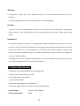
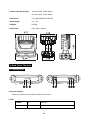
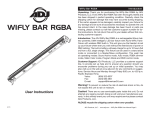
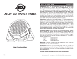
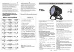
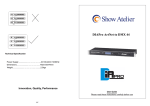
DIAPro ColorWash 10 f - "<" ._у� User Manual Please read the instruction carefully before use TABLE OF CONTENTS 1. Safety Instructions ....................................................................................................2 2. Technical Specifications ............................................................................................3 3. How To Set The Unit .................................................................................................4 3.1 Control panel ......................................................................................................4 3.2 Main Function ....................................................................................................5 3.3 Home Position Adjustment .............................................................................. 13 4. Control By Universal DMX Controller .................................................................... 13 4.1 DMX 512 Connection ....................................................................................... 13 4.2 Address Setting ................................................................................................ 14 4.3 DMX 512 Configuration ................................................................................... 16 5. Troubleshooting ..................................................................................................... 21 6. Fixture Cleaning ..................................................................................................... 21 1A 1. Safety Instructions WARNING Please read the instruction carefully which includes important information about the installation, usage and maintenance. Please keep this User Manual for future consultation. If you sell the unit to another user, be sure that they also receive this instruction booklet. Unpack and check carefully there is no transportation damage before using the unit. Before operating, ensure that the voltage and frequency of power supply match the power requirements of the unit. It’s important to ground the yellow/green conductor to earth in order to avoid electric shock. The unit is for indoor use only. Use only in a dry location. The unit must be installed in a location with adequate ventilation, at least 50cm from adjacent surfaces. Be sure that no ventilation slots are blocked. Disconnect main power before replacement or servicing. Make sure there are no flammable materials close to the unit while operating as it is fire hazard. Use safety cables when fixing this unit. DO NOT handle the unit by its head only, always carry by its base. Maximum ambient temperature is Ta: 40 degrees C. DO NOT operate it where the temperature is higher than this. Unit surface temperature may reach up to 75 degrees C. DO NOT touch the housing with bare‐hands during its operation. Turn off the power and allow about 15 minutes for the unit to cool down before replacing or serving. In the event of a serious operating problem, stop using the unit immediately. Never try to repair the unit by yourself. Repairs carried out by unskilled people can lead to damage or malfunction. Please contact the nearest authorized technical assistance center. Always use the same type spare parts. DO NOT touch any wire during operation as high voltage may cause electric shock. 2A Warning: To prevent or reduce the risk of electrical shock or fire, do not expose the unit to rain or moisture. The housing and lenses must be replaced if they are visibly damaged. Caution: There are no user serviceable parts inside the unit. Do not open the housing or attempt any repairs yourself. In the unlikely event your unit may require service, please contact your nearest dealer. Installation: The fixture should be mounted via its Omega Quick Release Clamp bracket. Always ensure that the unit is firmly fixed to avoid vibration and slipping while operating and make sure that the structure to which you are attaching the unit is secure and is able to support a weight of 10 times of the fixtures weight. Always use a safety cable that can hold 12 times of the weight of the fixture when installing. The equipment must be installed by professionals. It must be installed in a place where is out of the reach of people and no one can pass by or under it. 2. Technical Specifications ◇ Extremely small, fast and powerful LED moving beam. ◇ DMX Channels: 14/26 channels mode ◇ Outstanding color macro effect ◇ Variable strobe effects ◇ Blue white LCD display for easy navigation ◇ Perfect for stage, theatre, TV studio, rental and discotheques Input Voltage: AC 100 ~ 240V, 50/60Hz Power Consumption: 704W 3A Power Cable Daisy Chain: 6 Fixture Max. (230V, 50Hz) 3 Fixture Max. (120V, 60Hz) LED Source: 37 × 10W OSRAM OSTAR LED Beam Angel: 10° ~ 60° Weight: 19.5Kgs Dimension: 430 × 304 × 518mm 3. How To Set The Unit 3.1 Control panel 1. Function Display: Shows the various menus and the selected functions 2. LED: POWER ON Power On DMX ON DMX input present 4A 3. Button: MENU To select the programming functions DOWN To go backward in the selected functions UP To go forward in the selected functions ENTER To confirm the selected functions 4. DMX IN: DMX512 link, use 3/5‐pin XLR cable to link the unit and the DMX controller 5. DMX OUT: DMX512 link, use 3/5‐pin XLR cable to link the next unit and output DMX signal 6. MAINS IN: PowerCon connection from main power supply 7. MAIS OUT: PowerCon loop connection for main power supply to the next unit 8. Fuse (T 10A): Protects the unit from over‐voltage or short circuit 3.2 Main Function To select any of the given functions, press the MENU button until the required function is showing on the display. Select the function by pressing the ENTER button and the display will blink. Use the DOWN/UP buttons to change the mode. Once the required mode has been selected, press the ENTER button to setup, to go back to the functions without any change press the MENU button again. Press and hold the MENU button for about one second or wait for one minute to exit the menu mode. The main functions are shown overleaf: 5A 6A DMX Functions Enter MENU mode, select DMX Functions, press the ENTER button to confirm, use the UP/DOWN button to select DMX Address, DMX Channel Mode or View DMX Value. DMX Address To select DMX Address, press the ENTER button to show the DMX ADDRESS on the display. Use the UP/DOWN button to adjust the address from 001 to 512, press the ENTER button to setup. Press the MENU button back to the last menu or let the unit idle one minute to exit menu mode. DMX Channel Mode To select DMX Channel Mode, press the ENTER button to show the DMX CHANNEL MODE on the display. Use the UP/DOWN button to select Mode1 (14) or Mode2 (26), and press the ENTER button to setup. Press the MENU button back to the last menu or let the unit idle one minute to exit menu mode. View DMX Value To select View DMX Value, press the ENTER button to show the VIEW DMX VALUE on the display. Use the UP/DOWN button to view the DMX channel values. Press the MENU button back to the last menu or let the unit idle one minute to exit menu mode. Fixture Setting Enter MENU mode, select Fixture Setting, press the ENTER button to confirm, use the UP/DOWN button to select Pan Inverse, Tile Inverse, P/T Feedback, BL.O. P/T Moving, White Balance, Cooling Mode, Dimmer Curve or Dimmer Speed. Pan Inverse To select Pan Inverse, press the ENTER button to show the PAN INVERSE on the display. Use the UP/DOWN button to select No (normal) or Yes (pan inverse), press the ENTER button to setup. Press the MENU button back to the last menu or let the unit idle one minute to exit menu mode. Tilt Inverse To select Tilt Inverse, press the ENTER button to show the TILT INVERSE on the display. Use the UP/DOWN button to select No (normal) or Yes (tilt inverse), press the ENTER button to setup. Press the MENU button back to the last menu or let the unit idle one minute to exit menu mode. 7A P/T Feedback To select P/T Feedback, press the ENTER button to show the PAN/TILT FEEDBACK on the display. Use the UP/DOWN button to select No (Pan or tilt’s position will not feedback while out of step) or Yes (Feedback while pan/tilt out of step), press the ENTER button to setup. Press the MENU button back to the last menu or let the unit idle one minute to exit menu mode. BL.O. P/T Moving To select BL.O. P/T Moving, press the ENTER button to show the BLACKOUT WHILE PAN/TILT MOVING on the display, use the UP/DOWN button to select No (normal while pan/tilt moving) or Yes (blackout while pan/tilt moving), press the ENTER button to setup. Press the MENU button back to the last menu or let the unit idle one minute to exit menu mode. White Balance To select White Balance, press the ENTER button to show the WHITE BALANCE on the display, use the UP/DOWN button to select Red, Green or Blue. Once selected, press the ENTER button to confirm, and use the UP/DOWN button to adjust the value from 125 to 255, press the ENTER button to setup. Press the MENU button back to the last menu or let the unit idle one minute to exit menu mode. Cooling Mode To select Cooling Mode, press the ENTER button to show the COOLING MODE on the display. Use the UP/DOWN button to select Auto (Normal) or Low (Low speed). Once selected, press the ENTER button to setup. Press the MENU button back to the last menu or let the unit idle one minute to exit menu mode. Dimmer Curve To select Dimmer Curve, press the ENTER button to show the DIMMER CURVE on the display, use the UP/DOWN button to select Linear, Square Law, Inverse Squ. or S‐curve. Once selected, press the ENTER button to store. Press the MENU button back to the last menu or let the unit idle one minute to exit menu mode. 8A Linear: The increase in light intensity appears to be linear as DMX value is increased. Square Law: Light intensity control is finer at low levels and coarser at high levels. Inverse Square Law: Light intensity control is coarser at low levels and finger at high levels. S‐cure: Light intensity control is finger at low levels and high levels and coarser at medium levels. Dimmer Speed To select Dimmer Speed, press the ENTER button to show the DIMMER SPEED on the display. Use the UP/DOWN button to select Fast or Smooth. Once selected, press the ENTER button to setup. Press the MENU button back to the last menu or let the unit idle one minute to exit menu mode. Display Setting Enter MENU mode, select Display Setting, press the ENTER button to confirm, use the UP/DOWN button to select Display Inverse, Backlight Auto Off, Backlight Intensity ,Temperature unit or Display Warning. Display Inverse To select Display Inverse, press the ENTER button to show the DISPLAY INVERSE on the display. Use the UP/DOWN button to select No (normal) or Yes (display inverse). Once selected, press the ENTER button to store. Press the MENU button back to the last menu or let the unit idle one minute to exit menu mode. Backlight Auto Off To select Backlight Auto Off, press the ENTER button to show the BACKLIGHT AUTO OFF on the display. Use the UP/DOWN button to select No (display always on) or Yes (display goes off one minute after exiting menu mode). Once selected, press the ENTER button to confirm and store. Press the MENU button back to the last menu or let the unit idle one minute to exit menu mode. 9A Backlight Intensity To select Backlight Intensity, press the ENTER button to show the BACKLIGHT INTENSITY on the display. Use the UP/DOWN button to adjust the intensity from 1 (dark) to 10 (bright). Once selected, press the ENTER button to setup and store. Press the MENU button back to the last menu or let the unit idle one minute to exit menu mode. Temperature Unit To Select Temperature Unit, press the ENTER button to show the TEMPERATURE UNIT on the display. Use the UP/DOWN button to select ℃ or ℉, press the ENTER button to store. Press the MENU button back to the last menu or let the unit idle one minute to exit menu mode. Display Warning To select Display Warning, press the ENTER button to show the DISPLAY WARNING on the display. Use the UP/DOWN button to select No (Normal) or Yes (display will show the error warning when the unit went wrong), press the ENTER button to store. Press the MENU button back to the last menu or let the unit idle one minute to exit menu mode. Fixture Test Enter MENU mode, select Fixture Test, press the ENTER button to confirm, use the UP/DOWN button to select Auto Test or Manual Test Auto Test To select Auto Test, press the ENTER button to show the AUTO TEST on the display. Press the ENTER button, the unit will run built‐in programs to automatically test pan, tilt and zoom. Press the MENU button back to the last menu or exit menu mode after auto test. Manual Test To select Manual Test, press the ENTER button to show the MANUAL TEST on the display. Press the ENTER button, and then use the UP/DOWN button to select channel, and adjust the channel value. Once selected, press the ENTER button to setup, the fixture will run as the channel value indicates. Press the MENU button back to the last menu or exit menu mode let the unit idle one minute. (All channels value will become 0 after exiting Manual Test menu) 10A Fixture Information Enter MENU mode, select Fixture Information, press the ENTER button to confirm, use the UP/DOWN button to select Fixture use time, Lamp On tme or Firmware Version. Fixture use time To select Fixture use time, press the ENTER button to show the FIXTURE USE TIME on the display. Press the ENTER button, the fixture working hours will show on the display. Press the MENU button to exit. Lamp On time To select Lamp On time, press the ENTER button to show the LAMP ON TIME on the display. Press the ENTER button to confirm, then use the UP/DOWN button to select Exit or Reset Time, press the ENTER button to store. Press the MENU button back to the last menu or exit menu mode let the unit idle one minute. Firmware Version To select Firmware Version, press the ENTER button to show the FIRMWARE VERSION on the display. Press the ENTER button and the fixture software version will show on the display. Press the MENU button to exit. Reset Functions Enter MENU mode, select Reset Function, press the ENTER button to confirm, use the UP/DOWN button to select Pan/Tilt, Zoom or All. Pan/Tilt To Select Pan/Tilt, press the ENTER button to show the PAN/TILT on the display. Use the UP/DOWN button to select Yes (the unit will run built‐in program to reset pan and tilt to their home positions) or No, press the ENTER button to store. Press the MENU button to exit menu mode. Zoom To select Zoom, press the ENTER button to show the ZOOM on the display. Use the UP/DOWN button to select Yes (the unit will run built‐in program to reset zoom to its home positions) or No, press the ENTER button to store. Press the MENU button to exit menu mode. 11A All To select All, press the ENTER button to show the ALL on the display. Use the UP/DOWN button to select Yes (the unit will run built‐in program to reset all motors to their home positions) or No, press ENTER button to store. Press MENU button to exit menu mode. Special Functions Enter MENU mode, select Special Functions, press the ENTER button to confirm, use the UP/DOWN button to select Fixture Maintenance or Factory Setting. Fixture Maintenance To select Fixture Maintenance, press the ENTER button to show the FIXTURE MAINTENANCE on the display. Use the UP/DOWN button to select Interval or Remain Time. Interval To select Interval, press the ENTER button to confirm, the interval time will be shown on the display. Press the MENU button to exit. Remain Time To select Remain Time, press the ENTER button to confirm, the remaining time will be shown on the display. Press the ENTER button to confirm, use the UP/DOWN button to select Exit or Reset time, press the MENU button to exit. Factory Setting To select Factory Setting, press the ENTER button to show the FACTORY SETTING on the display. Press the ENTER button to confirm, use the UP/DOWN button to select No or Yes (the fixture will reset to factory settings and exit menu mode). 12A 3.3 Home Position Adjustment In the main functions, hold the ENTER button for at least 3 seconds into offset mode, use the DOWN/UP button up to select Pan Offset, Tilt Offset or Zoom Offset, and press the ENTER button to confirm. Use the DOWN/UP button to adjust the home position of the Pan, Tilt or Zoom, Once the position has been selected, press the ENTER button to setup, to go back to the functions without any change press the MENU button again. Press and hold the MENU button about one second or wait for about one minute to exit the menu mode. 4. Control By Universal DMX Controller 4.1 DMX 512 Connection 13A 1. If you using a controller with 5 pins DMX output, you need to use a 5 to 3 pin adapter‐cable. 2. The last units DMX cable has to be terminated with a 120 ohm 1/4W resistor between pin 2(DMX‐) and pin 3(DMX+) of a 3‐pin XLR‐plug and plug it in the DMX‐output of the last unit. 3. Connect the unit together in a `daisy chain` by XLR plug from the output of the unit to the input of the next unit. The cable can not branched or split to a `Y` cable. DMX 512 is a very high‐speed signal. Inadequate or damaged cables, soldered joints or corroded connectors can easily distort the signal and shut down the system. 4. The DMX output and input connectors are pass‐through to maintain the DMX circuit, when one of the units’ power is disconnected. 5. Each fixture unit needs to have an address set to receive the data sent by the controller. The address number is between 0‐511 (usually 0 & 1 are equal to 1). 6. The end of the DMX 512 system should be terminated to reduce signal errors. 7. 3 pin XLR connectors are more popular than 5 pin XLR. 3 pin XLR: Pin 1: GND, Pin 2: Negative signal (‐), Pin 3: Positive signal (+) 5 pin XLR: Pin 1: GND, Pin 2: Negative signal (‐), Pin 3: Positive signal (+), Pin 4/Pin 5: Not used. 4.2 Address Setting If you use a universal DMX controller to control the units, you have to set DMX address from 1 to 512 so that the units can receive DMX signal. Press the MENU button to enter menu mode, select DMX Functions, press the ENTER button to confirm, use the UP/DOWN button to select DMX Address, press the ENTER button to confirm, the present address will blink on the display, use the UP/DOWN button to adjust the address from 001 to 512, and press the ENTER button to store. Press the MENU button back to the last menu or let the unit idle 7 seconds to exit menu mode. 14A Please refer to the following diagram to set the DMX address for the first 4 units: Channel mode Unit 1 Address Unit 2 Address Unit 3 Address Unit 4 Address 14 channels 1 15 29 43 26 channels 1 27 53 79 15A 4.3 DMX 512 Configuration 14 Channels Mode: CHANNEL 1 2 3 4 5 VALUE 000‐255 000‐255 000‐255 000‐255 000‐255 6 000‐009 010‐014 015‐255 7 000‐255 8 9 10 000‐019 020‐024 025‐064 065‐069 070‐084 085‐089 090‐104 105‐109 110‐124 125‐129 130‐144 145‐149 150‐164 165‐169 170‐184 185‐189 190‐204 205‐209 210‐224 225‐229 230‐244 245‐255 000‐255 000‐255 FUNCTION PAN PAN FINE TILT TILT FINE PAN/TILT SPEED fast slow SPECIAL FUNCTIONS No function Reset No function DIMMER 0%~100% SHUTTER Blackout Open Strobe 1: fast slow Open Strobe 2: opening pulse, fast slow Open Strobe 3: closing pulse, fast slow Open Strobe 4: random strobe, fast slow Open Strobe 5: random opening pulse, fast slow Open Strobe 6: random closing pulse, fast slow Open Strobe 7: burst pulse, fast slow Open Strobe 8: random burst pulse, fast slow Open Strobe 9: sine wave, fast slow Open Strobe 10: burst, fast slow Open RED (0% 100%) GREEN (0% 100%) 16A 11 12 13 000‐255 000‐255 000‐009 010‐014 015‐019 020‐024 025‐029 030‐034 035‐039 040‐044 045‐049 050‐054 055‐059 060‐064 065‐069 070‐074 075‐079 080‐084 085‐089 090‐094 095‐099 100‐104 105‐109 110‐114 115‐119 120‐124 125‐129 130‐134 135‐139 140‐144 145‐149 150‐154 155‐159 160‐164 165‐169 170‐174 175‐179 180‐201 202‐207 208‐229 230‐234 BLUE (0% 100%) WHITE (0% 100%) COLOR MACRO Open LEE 790 – Moroccan Pink LEE 157 – Pink LEE 332 – Special Rose Pink LEE 328 – Follies Pink LEE 345 – Fuchsia Pink LEE 194 – Surprise Pink LEE 181 – Congo Blue LEE 071 – Tokyo Blue LEE 120 – Deep Blue LEE 079 – Just Blue LEE 132 – Medium Blue LEE 200 – Double CT Blue LEE 161 – State Blue LEE 201 – Full CT Blue LEE 202 – Half CT Blue LEE 117 – Steel Blue LEE 353 – Lighter Blue LEE 118 – Light Blue LEE 116 – Medium Blue Green LEE 124 – Dark Green LEE 139 – Primary Green LEE 089 – Moss Green LEE 122 – Fern Green LEE 738 – JAS Green LEE 088 – Lime Green LEE 100 – Spring Yellow LEE 104 – Deep Amber LEE 179 – Chrome Orange LEE 105 – Orange LEE 021 – Gold Amber LEE 778 – Millennium Gold LEE 135 – Deep Gold Amber LEE 164 – Flame Red Open Color wheel rotation effect Clockwise, fast slow Stop (this will stop wherever the color is at the time) Counter‐clockwise, slow fast Open Random color 17A 235‐239 240‐244 245‐249 250‐255 14 000‐255 Fast Medium Slow Open ZOOM wide narrow 26 Channels Mode: CHANNEL 1 2 3 4 5 VALUE 000‐255 000‐255 000‐255 000‐255 000‐255 6 000‐255 7 000‐009 010‐014 015‐255 8 000‐255 9 000‐019 020‐024 025‐064 065‐069 070‐084 085‐089 090‐104 105‐109 110‐124 125‐129 130‐144 145‐149 150‐164 165‐169 170‐184 185‐189 FUNCTION PAN PAN FINE TILT TILT FINE PAN/TILT SPEED fast slow ZOOM wide narrow SPECIAL FUNCTIONS No function Reset No function DIMMER 0%~100% SHUTTER Blackout Open Strobe 1: fast slow Open Strobe 2: opening pulse, fast slow Open Strobe 3: closing pulse, fast slow Open Strobe 4: random strobe, fast slow Open Strobe 5: random opening pulse, fast slow Open Strobe 6: random closing pulse, fast slow Open Strobe 7: burst pulse, fast slow Open 18A 10 11 12 13 14 190‐204 205‐209 210‐224 225‐229 230‐244 245‐255 000‐255 000‐255 000‐255 000‐255 000‐009 010‐017 018‐024 025‐032 033‐039 040‐047 048‐054 055‐061 062‐069 070‐076 077‐084 085‐091 092‐099 100‐106 107‐113 114‐121 122‐128 129‐136 137‐143 144‐151 152‐158 159‐165 166‐173 174‐180 181‐188 189‐195 196‐203 204‐210 211‐217 218‐225 226‐232 233‐240 Strobe 8: random burst pulse, fast slow Open Strobe 9: sine wave, fast slow Open Strobe 10: burst, fast slow Open RING 1 RED (0% 100%) RING 1 GREEN (0% 100%) RING 1 BLUE (0% 100%) RING 1 WHITE (0% 100%) RING 1 COLOR PRESET Open Color1 Color2 Color3 Color4 Color5 Color6 Color7 Color8 Color9 Color10 Color11 Color12 Color13 Color14 Color15 Color16 Color17 Color18 Color19 Color20 Color21 Color22 Color23 Color24 Color25 Color26 Color27 Color28 Color29 Color30 Color31 19A 15 16 17 18 19 20 21 22 23 24 241‐247 248‐255 000‐255 000‐255 000‐255 000‐255 000‐255 000‐255 000‐255 000‐255 000‐255 000‐255 25 000‐007 008‐022 023‐037 038‐052 053‐067 068‐082 083‐097 098‐112 113‐127 128‐142 143‐157 158‐172 173‐187 188‐202 203‐217 218‐232 233‐247 248‐255 26 000‐255 Color32 Color33 RING 2 RED (0% 100%) RING 2 GREEN (0% 100%) RING 2 BLUE (0% 100%) RING 2 WHITE (0% 100%) RING 2 COLOR PRESET (The same as CH14:RING 1 COLOR PRESET) RING 3 RED (0% 100%) RING 3 GREEN (0% 100%) RING 3 BLUE (0% 100%) RING 3 WHITE (0% 100%) RING 3 COLOR PRESET (The same as CH14:RING 1 COLOR PRESET) RING COLOR MACRO Blackout Macro1 Macro2 Macro3 Macro4 Macro5 Macro6 Macro7 Macro8 Macro9 Macro10 Macro11 Macro12 Macro13 Macro14 Macro15 Macro16 Mocro17 COLOR MACRO SPEED Slow fast 20A 5. Troubleshooting Following are a few common problems that may occur during operation. Here are some suggestions for easy troubleshooting: A. The unit does not work, no light and the fan does not work 1. Check the connection of power and main fuse. 2. Measure the mains voltage on the main connector. 3. Check the power on LED. B. Not responding to DMX controller 1. DMX LED should be on. If not, check DMX connectors and cables to see if link properly. 2. If the DMX LED is on and no response to the channel, check the address settings and DMX polarity. 3. If you have intermittent DMX signal problems, check the pins on connectors or on PCB of the unit or the previous one. 4. Try to use another DMX controller. 5. Check if the DMX cables run near or run alongside to high voltage cables that may cause damage or interference to DMX interface circuit. C. One of the channels is not working well 1. The stepper motor might be damaged or the cable connected to the PCB is broken. 2. The motor’s drive IC on the PCB might be out of condition. 6. Fixture Cleaning The cleaning must be carried out periodically to optimize light output. Cleaning frequency depends on the environment in which the fixture operates: damp, smoky or particularly dirty surrounding can cause greater accumulation of dirt on the unit’s optics. Clean with soft cloth using normal glass cleaning fluid. Always dry the parts carefully. Clean the external optics at least every 30 days. 21A