1
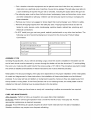
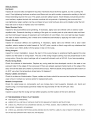
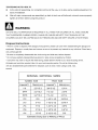
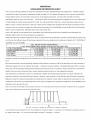
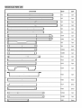
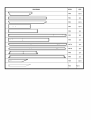
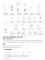
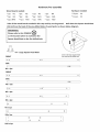
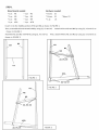
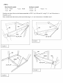
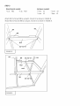
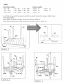
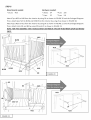
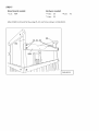
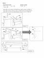
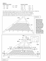
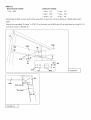
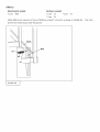
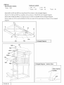
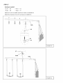
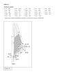
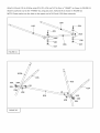
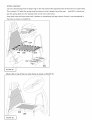
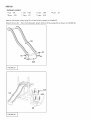
WOODLAND
PLAY SET
MODEL # WP-336R
OWNER'S
ASSEMBLY
MANUAL
INSTRUCTION
CARE MAINTENANCE
AND USER'S GUIDE
FOR RESIDENTIAL
CAUTION
USE ONLY
This product is intended for use by children from ages 3 to 8.
This unit is designed for the use of 8 occupants, with a maximum
100 pounds
pounds
(45.4kgs)
(363.2kgs).
PLEASE RETAIN THESE INSTRUCTIONS
for each. Combined
Assembly
requires
weight
is not to exceed 800
at least FOUR adults.
FOR FUTURE REFERENCE. KEEP THEM IN A SAFE PLACE
WHERE YOU CAN REFER TO THEM AS NEEDED.
Customer
Service
Do not return to the store,
For customer
weight
service,
please visit wwwos
owerltdonet
SPORTSPOWER LTD
FLAT M, 3/FLOOR, KAISER ESTATE PHASE 3,
11 HOK YUEN STREET, HUNGHOM,
KOWLOON, HK
of
Dear Valued Customer,
Congratulations
on your Wood Play Set purchase!
To assure the safety of your children while they enjoy many great moments
please
assure you thoroughly
instructions
proper,
that will assure
read and follow this important
a safe play experience.
manual.
All instructions
of outdoor
It contains
fun,
specific
must be followed
safety
to assure
safe use of your Wood Play Set.
Age Recommendations:
Children
ages 3-8
Commercial
Use:
Commercial
usage is not warranted.
This is a residential
Wood
Play Set only.
IMPORTANT:
•
Children
must NOT play on this set until it is properly
•
The Wood Play Set must be properly
assembled
installed and anchored
and inspected by an adult.
BEFORE
children can play on the Wood
Play Set.
•
You MUST read and follow all instructions in this manual
before
installing or attempting to use the
Wood Play Set.
Failure to follow these important
violations
that may possibly
and assembly
Please
may result in the warranty
being voided
result in an injury. Please watch your children
carefully
and/or safety
during the installation
of the Wood Play set to avoid injury.
also pay close attention
safe condition
requirements
for maximum
to the periodic
enjoyment
maintenance
of backyard
that is required to keep you Wood
Play Set in a
fun!
WARNING
BEFORE
YOU BEGIN ASSEMBLY!!!
•
Take a complete
inventory
•
Sort and lay out the wood pieces.
during the assembly
wood. Some wooden
straighten
of components
process,
out when assembled.
Sort all hardware
according
•
Find a safe play location.
Label each piece of wood for easy reference.
write the board's
components
•
using the parts list.
letter on masking
tape and adhere to each piece of the
may twist or warp in the carton after packaging.
You may also see some cracking
to size. Do not worry if extra hardware
o You MUST install the Wood Play Set on level ground.
installation.
The manufacturer
installation.
Installing
set to become
For easy identification
cannot assume
on sloping ground
loose and unstable.
Usually, these parts
of the grain. This is normal.
is included.
Uneven ground
responsibility
must be leveled
prior to
for any failure from incorrect
will put stress on all the joints, which will cause the
o Finda locationwhere the equipmentcan be placedmorethan 6 feetfromany structureor
obstruction(ex:electricalwires,branches,house,fence,garage)The safe playarearefersto
a zoneextending6' beyondthe gym set on all sides,includingthe spaceabovethe gym set.
o The safe playarea mustbe free of all structures,landscaping,tressandbranches,rocks,wires
andother obstaclesto safe play. Childrencan beseriouslyinjuredrunningor swinginginto
theseobstacles.
o Removeany rocks or anyjaggedor sharpobjectthatcould endangeryour children's'safety.
o Removeall trippinghazardsfromthe safe playarea.Trippinghazardsincludebut are not
limitedto: roots,stumps,rocks,landscaping,sprinklerheads,railroadties,plumbing,and
electricalconnections.
o Do NOT installyourgym setovergravel,asphalt,packedearthor any otherhard surface.The
followingis a list of recommendedgroundcoversfrom the ConsumerProductSafety
Commission.
ASSEMBLY
Climbing
SUGGESTED MATERIAL
UNCOMPRESSED
Double
Shredded
9"
Uniform
Wood
Bark Mulch
Chips
12"
Fine Sand
12"
TIPS
(If your set has climbing
end of each dowel must be secured
the wood, you must pre-drill
is detailed
a pilot hole for the screws
integrity
As noted and diagrammed
rungs.) Once the dowel is installed
by a screw through
and illustrated
Metal plates: The structural
precisely.
12"
Fine Gravel
Rungs/Dowels.
the dowels
using a 1/8" drill bit. The procedure
in these instructions
and must be followed
of the play set is dependent
in these instructions,
the installation
Ground
stakes:
tower is perpendicular
required
of the metal plates.
of these metal plates must be followed
make sure they are angled away from
towers,
the metal plates must be
to the top ladder.
Unless you have loose or sandy soil, cementing
is neither
recommended
nor required.
CARE AND MAINTENANCE:
After Assembly:
Perform a follow-up
Bi-Monthly:
Perform a thorough
appropriate
maintenance
Annually:
Weather
Wood refinishing
conditions
inspection
as deemed
is typically
may require
inspection
one week after initial installation.
twice a month for the life of your wood play set. Provide
necessary
required
more frequent
to install
precisely.
on the proper installation
If your play set has end ladders or swing beam supports,
so that each climbing
in the ladder rail, the
the ladder rail into the dowel end. To avoid splitting
the top ladder or swing beam. If the Wood Set has one or two climbing
installed
DEPTH
at twelve-month
refinishing.
intervals
from the date of installation.
What to Inspect:
Hardware:
Inspect
all nuts and bolts and tighten
wood. Over-tightening
thread extending
wood surface,
hardware
beyond
if required.
crushes
Hardware
should
be firmly against,
wood fibers and can split wooden
the wood. This poses a severe safety hazard.
larger washers
can be purchased
components
If bolt threads
replace the bolt with a shorter one that will not protrude.
over-tightening,
but not crushing
If splintering
at your local hardware
resulting
protrude
in the bolt
beyond
has occurred
store and installed
the
the
from
under the bolt
head. Be sure to reuse or replace your lock washers.
Major
Wooden
Parts:
Inspect for structural
repellent
defects and splintering.
stain. Seasonal
are the most frequent
checking
causes
with stain to resist weathering.
Dowels
(Rungs)
Inspect
for structural
repellent,
exterior
defects
Swing
or cracking
of expansion
lightly sand and refinish with an exterior
of the grain on wooden
and contraction
and splintering.
If necessary,
lightly
and refinish
with
a clear
water
that
ability to firmly grasp or step on the rungs.
hangers
and the ladder or swing beam. The axis of the swing hanger
swing motion.
Swing
installation.
Assure
Spray the nylon bushings
the bend of the swing
with a household
hanger
lubricant
of deterioration.
Replace
seat, remove the seats and chains to prevent serious
do NOT use when the temperature
tightly
against
must be perpendicular
such as WD-40,
the stop
to the
if you hear squeaking.
exposed
injury. Remove
drops below 32 degrees
cracks
in the seat or has
metal inserts
on the edge of the
plastic swing seats and take indoors
or
F.
and Chains
Check for evidence
wear is found.
bushing
any swing seat that has developed
metal in the edges of the swing seat. If there are already
Cables
is positioned
Seats
for evidence
exposed
Metallic
new stain or paint.
oil. Do NOT paint, varnish or finish rungs with any substance
washer
Ropes,
by applying
sand
for correct
Check
parts is quite natural water and heat
periodically
Inspect
Plastic
water
of wood fibers. Our wood set has been treated
But it needs to be maintained
sealant or boiled linseed
may reduce your child's
If necessary,
of deterioration.
Contact
Ropes,
cables and chains should
our service center for replacement
be removed
and replaced
if excessive
parts.
Components
Check
for rusted
areas
on components
repaint
using a non lead-based
such
as monkey
bars, hand
paint that meets the requirements
supports,
brackets,
etc. Sand
and
of Title 16 CRF part 1303.
Play Area
Inspect to assure that the swing set has settled
properly
and the location of the set is still level.
AT THE BEGINNING OF EACH PLAY SEASON:
•
TIGHTEN ALL HARDWARE.
•
LUBRICATE ALL METALLIC MOVING PARTS PER MANUFACTURER'S
•
CHECK ALL PROTECTIVE COVERINGS ON BOLTS, PIPES, EDGES, AND CORNERS. REPLACE IF THEY
INSTRUCTIONS.
ARE LOOSE, CRACKED, OR MISSING.
•
CHECK ALL MOVING PARTS INCLUDING SWING SEATS, ROPES, CABLES, AND CHAINS FORWEAR, RUST,
OR OTHER DETERIORATION.
REPLACE AS NEEDED.
• CHECKMETALPARTSFORRUST.IFFOUND,SANDANDREPAINT
USINGANONLEAD-BASED
PAINT
MEETING
THEREQUIREMENTS
OF 16CFR1303.
• CHECKALLWOOD
MEMBERS
FORDETERIORATION
ANDSPLINTERS.
SANDDOWNSPLINTERS
AND
REPLACE
DETERIORATING
WOODMEMBERS.
• REINSTALL
ANYPLASTIC
PARTS,SUCHASSWINGSEATSORANYOTHERITEMSTHATWEREREMOVED
FORTHECOLDSEASON.
• RAKEANDCHECKDEPTHOFLOOSEFILLPROTECTIVE
SURFACING
MATERIALS
TOPREVENT
COMPACTION
ANDTOMAINTAIN
APPROPRIATE
DEPTH.REPLACE
ASNECESSARY.
TWICE A MONTH DURING PLAY SEASON:
•
TIGHTEN ALL HARDWARE.
•
CHECK ALL PROTECTIVE COVERINGS ON BOLTS, PIPES, EDGES, AND CORNERS. REPLACE IF THEY
ARE LOOSE, CRACKED, OR MISSING.
•
RAKE AND CHECK DEPTH OF LOOSE FILL PROTECTIVE SURFACING MATERIALS TO PREVENT
COMPACTION AND TO MAINTAIN APPROPRIATE
DEPTH. REPLACE AS NECESSARY.
ONCE A MONTH DURING PLAY SEASON:
•
LUBRICATE ALL METALLIC MOVING PARTS PER MANUFACTURER'S
•
CHECK ALL MOVING PARTS INCLUDING SWING SEATS, ROPES, CABLES, AND CHAINS FORWEAR, RUST,
OR OTHER DETERIORATION.
REPLACE AS NEEDED.
AT THE END OF EACH PLAY SEASON OR WHEN THE TEMPERATURER
•
INSTRUCTIONS
DROPS BELOW 32 °F.
REMOVE PLASTIC SWING SEATS AND OTHER ITEMS AS SPECIFIED BY THE MANUFACTURER
AND TAKE
INDOORS OR DO NOT USE.
•
RAKE AND CHECK DEPTH OF LOOSE FILL PROTECTIVE SURFACING MATERIALS TO PREVENT
COMPACTION AND TO MAINTAIN APPROPRIATE
In general,
maintenance
should
DEPTH. REPLACE AS NECESSARY.
be performed
at any time it is deemed
necessary.
USER'S GUIDE
WARNING
CAUTION
READ BEFORE USING THIS EQUIPMENT
GENERAL
INSTRUCTION
•
Read this manual
and follow all instructions before using and assembling this unit.
•
Observing
•
Recommending
•
This unit is designed
the following
On-site
weight of 100 pounds
pounds.
statements
and warnings
adult supervision
reduces
the likelihood of serious
fatal injury.
for children of all ages at all times.
to be used safely by up to 8 children
(45.4 kgs) each, simultaneously,
between
the age of 3 to 8, with a maximum
not to exceed a combined weight of 800
WARNING
•
Lawn swings
is designed
for use by children
two can result in entrapment
between
facing position or with legs between
the opening
•
causing
entrapment
This unit must be assembled
someone
over two years of age. Use by Children
the seat and back areas. NEVER
the seat and backrest
of the child's
because
the child's
in rearward
body may pass through
by a capable
adult person.
We suggest
that you get
to help.
Children
•
Always
•
Do not allow swing set near any obstruction
must not use the equipment
until properly
assembled
and anchored.
locate the swing set on level ground!
than 6ft (1.8m)
branches,
from
laundry
any structures
line, electrical
or sharp object
or obstacles
! Place gym set on level ground,
such as fence,
garage,
If the seats of swing, glide or slide are wet, do not use this equipment.
•
If any bolts & nuts are missing,
•
A capable
adult should
such as jumping
Provide
shed
house,
not less
overhanging
wires.
•
•
place children
head.
and disassembled
•
•
under the age of
do not use this equipment!
supervise
the use of this equipment
at all times.
Do not allow reckless
playing,
off swing, slide, or Glide ride.
proper surface
material
cover for this equipment
prior to using this equipment.
Do not allow more than one child to play on the swing, trapeze
bar or slide at any one time. Children
shall take turns using the slide.
•
Do not allow child to stand on the swing seats or glide ride.
•
Instruct
children
not to walk too close in front of, behind,
keep a safe distance
•
Instruct
children
moving
items. Instruct
children
to
away to avoid being struck by items in play.
not to twist swing chains or ropes or loop them over the top support
reduce the strength
children
or between
bar since this may
of the chain or rope.
•
Instruct
to avoid swinging
empty seats.
•
Teach children
•
Instruct
children
not to use the equipment
•
Instruct
children
not to get off equipment
to sit in the center of the swing play items, with their full weight
in any manner
in the seats.
other than intended.
while it is in motion.
Do not allow children
to jump from moving
play items.
•
Do not allow children
•
Do not stand on the lawn swing when using this ride. One child per seat only!
•
Check the openings
be potentially
•
between
hazardous
of roller slides for foreign
materials
that could
to users.
that the gym set be placed
(including
) are placed
concrete
when it is wet.
rollers and sliding surfaces
It is recommended
prevent
•
to climb or play on equipment
below
in concrete.
Be certain that all anchoring
the level of the playing
surface
or below
to lean to the side when riding on other rides, structural
members
ground
devices
level to
tripping.
Do not allow children
on collide with
other playmates.
•
Do not install home playground
other hard surface.
•
Do anchor
all gyms.
equipment
A fall onto a hard surface
over concrete,
asphalt,
can result in serious
packed
earth, grass,
injury to the equipment
carpet, or any
user.
•
•
•
•
•
•
•
•
•
•
•
•
•
•
If the swingset is set up ongroundswith sandysoilcondition,it mustbeanchoredwithconcretefooting
(Concretenot included). On-siteadultsupervisionfor childrenof all agesis recommended.
Instructchildrennot to walkcloseto, in frontof, behind,or betweenmovingitems.
Instructchildrennot to twistswing chainsor ropesor loopthem overthe top supportbar sincethis may
reducethe strengthof the chain or rope.
Instructchildrenalwaysto holdthe swingchainwhen playon.
Teachchildrento sit in the centerof the swingswith theirfull weighton the seats,
Instructchildrennot to usethe equipmentin a mannerotherthan intended,
Instructchildrennot to get off equipmentwhile it is in motion.
Adultshoulddresschildrenappropriately(exampleswouldincludethe use of well-fittingshoesandthe
avoidanceof ponchos, scarf's, and other loose-fittingshoes and other loose-fittingclothing that is
potentiallyhazardouswhileusing equipment).
Please verify that suspendedclimbing ropes, chain, or cable are secured at both ends, and that
suspendedclimbingropes,chain,or cable cannotbe loopedbackon itself.
Instructchildrennot to attach itemsto the playgroundequipmentthat are not specificallydesignedfor
use with the equipment,such as, but not limitedto, jump ropes,clothesline,pet leashes,cables and
chainas they my causea strangulationhazard.
Instructchildrennot to go down slide headfirst.
Checkslide bedfor extremeheat beforelettingchildrenuse slide(Whenexposedto directsunlight)
Do not allow childrento climbon swingfrom structuralmembers(Legs,top bar and chin bar).These
are structuralcomponentsonlyand NOTplayfeatures.
•
Pleasesavethis instructionmanualfor future referenceand revieweachseason.
•
Plasticcomponentsshouldbe replacedeverythreeyears.
Advisingthe buyerto instructchildrento removetheir bikeor othersportshelmetbeforeplayingon the
playgroundequipment.
WARNING FOR TRAMPOLINE
•
Lateral
clearance
play areas°
is essential°
Maintain
Place the trampoline
away from walls,
Do not jump onto the trampoline
•
Do not allow more than one person on the trampoline
•
Use trampoline
only with mature,
•
Avoid bouncing
too high. Use the handle bar to control bounce.
•
Climb on and off the trampoline,
ground when dismounting,
•
Avoid bouncing
trampoline
Avoid bouncing
•
Bounce
And other
while using the swing set.
knowledgeable
it is a dangerous
at a time.
adult supervision.
practice
or to jump onto the trampoline
to jump from the trampoline
when mounting.
to the floor or
Do not use the trampoline
as
to other objects.
too high. Stay low until bounce control
can be accomplished.
•
Fences,
a clear space on all sides of the trampoline°
•
a springboard
structures,
Control
and repeated
is more important
landing in the center of the
than height.
when tired. Keep turns short.
only when the surface
of the bed is dry. Wind or air movement
should
be calm and gentle. The
•
trampolinemustnot be usedin gusty or severewinds.
Neveruse the trampolinewithoutattachingthe frame paddingproperlysecureto the frameandin correct
position prior to each using of trampoline.
•
Adequate
Provide
overhead
clearance
clearance
is essential.
A minimum
of 24 ft from ground
for wires, tree limbs, and other possible
•
Use the trampoline
on a level surface
•
Use the trampoline
in a well-lighted
level is recommended.
hazards.
before use.
area. Artificial
illumination
may be required for indoor or shady
areas.
•
Remove
any obstructions
•
The owner and supervisors
specified
•
from beneath
the trampoline.
of the trampoline
are responsible
in the use instructions.
The trampoline
is designed
to withhold
a certain amount
one person at any one time uses the trampoline.
Jumpers
•
Please
should
of weight and use. Please
Also, the person should weight
either wear socks, gymnastics
shoes, or be barefoot
be aware that street shoes or tennis shoes should
order to prevent the trampoline
mat. Also, jumpers
should
remove all sharp objects
Any type of sharp or pointed
objects
•
Do not mount the trampoline
by grabbing
the mat of the trampoline
Do not dismount
the ground.
make sure that only
less than 100 pounds.
when using the trampoline.
not be worn while using the trampoline.
mat from getting cut or damaged
•
•
to make all users aware of practices
please do not allow any pets onto the
from their person prior to using the trampoline.
should be kept off the trampoline
the frame pad, stepping
mat at all times.
onto the springs,
or by jumping
from any object ( I.E. a deck, roof, or ladder, or any stations
by jumping
If small children
off the trampoline
are playing
In
and landing
on the trampoline,
on the ground,
regardless
onto
of the swing set)
of the makeup of
they may need help in mounting
and
dismounting.
•
No more than one person jump on the trampoline
trampoline
will increase
the chance of getting
•
Do not jump or bounce for prolonged
•
Always
have a supervisor
•
Always
inspect
Please
be make sure to check following
If have, please
* Missing,
the trampoline
replace
improperly
* Punctures,
injured..
of time or too high for a number
you when you are on the trampoline,
before each use and replace
conditions
of jumps.
swing seat, glide ride, slide.
any worn, defective,
that could represent
potential
or missing
hazards
parts.
before using:
them.
positioned,
damaged
or insecurely
attached
frame padding.
frays, tears, or holes worn in the bed or frame padding.
* Deterioration
* Broken,
watching
periods
at any one time. More than one person jump on the
in the stitching
missing
or damaged
or fabric of the bed or frame padding.
springs
* A bent or broken frame.
* A sagging,
broken bed
* Sharp protrusions
* Protrusions
on the frame or suspension
of any types(especially
* Loose stitching
system.
sharp typed) on the frame, springs
or any kind of deterioration
or mat.
of the mat
•
Avoid bouncing
too high. Use the handle bar to control bounce.
•
Do not attempt to jump over the netting to the swing set. Do not intentionally
•
Do not attach anything
to the netting.
rebound
off the netting.
TIGHTENINGNUTS& BOLTS
•
At the startof assembling,do not tightenbolt/nutall the way, so to allowsome possibleadjustment,for
easeof installation.
•
Afterall majorcomponentsare assembled,go backto lookover all boltsand nutsand screwsproperly
tightenall of them beforeusingthis product.
WARNING
ON-SITE ADULT SUPERVISION
THAT SUSPENDED
CHILDREN
Disposal
CLIMBING
IS REQUIRED
AT ALL TIMES FOR CHILDREN
OF ALL AGES. ENSURE
ROPES, CHAINS OR CABLES ARE KETP TIGHT ENOUGH
CAN NOT BE LOOPED
BACK ON THEMSELVES
SO THE
AND ARE KEPT SECURE AT BOTH ENDS.
Instructions
* When it is time to dispose of the playground
equipment, please use care when disassembling
the playground
equipment. Dispose in a safe place and manner so as not to present any hazards to any individual. Wear heavy
duty working gloves!
* Be sure to completely
disassemble
the whole swing and slide sets, before disposal.
* Do not leave partially disassembled
* Consumer
equipment in area where accessible by children.
may wish to recycle the steel tubing, please take the frame to your local recycling centre.
All plastic part could be recycled, take it to your local recycling
with any disassembled
centre. Do not let children
play
parts destined for disposal, such as chain, slide, tubings, bolts, nuts,
screws!
NAMED
SiZE
TRUE
SIZE
2.5"i5.3
3.2"15o3
1-I12"!-I_
2"4
5" 10
5"15.3
10"10
Estimaied
Sizing
Due to Molding
of W_d
IMPORTANT
CONSUMER
INFORMATION
SHEET
The Consumer Product Safety Commission estimates that about 100,000 Playground equipments.
Related injuries
resulting from falls to the ground equipment treated annually In U.S. hospital emergency rooms. Injuries involving this
hazard pattern tend to be among the most serious of all playground injuries, and have the potential to be fatal,
particularly when the injury is to the head.
The surface under and around playground equipment can be a major factor
in determining the injury-causing potential of a fall. It is self evident that a fall onto a shock absorbing surface is less
likely to cause a serious injury than a fall onto a hard surface. Playground equipment should never be placed on hard
surfaces such as concrete or asphalt and while grass may appear to be acceptable it may quickly turn to hard packed
earth in areas of high traffic. Shredded bark mulch,wood chips fine
sand or fine gravel are considered to be acceptable shock absorbing surface when installed and maintained at a
sufficient depth under and around playground equipment.
Table below lists the maximum height from which a child would not be expected to sustain a life-threatening head injury
in a fall onto four different loose-fill surfacing materials if they are installed and maintained at depths of 6" (15.25CM), 9"
(22.9CM), and 12" (30.5CM).
FALL HEGH½ iN FEET
A UFE THRE/_£NING HEAD INJURY
TY_ OF MATER_
D_bb s
ba_: mu/lch
Chi£s
Fine Saad
F_ne
WHICH
[D NOT BE _PECTED
6_ (IE2_,;M)DEP_
9 ° (_.gCM!
D
10" (25.4CM)
T (17.
)
5" (12 7CM!
T (178CM)
5° (12.7CM_
1T (_.5CM)
DEPTH
11° (27.NCM}
9 _ (_.86CM)
However,it should be recognized that all injuries due to falls cannot be prevented no matter what surfacing material is
used.
We recommend that a shock absorbing material should extend a minimum of 6ft in all directions from the perimeter of
stationary equipment such as climbers and slides.
However, because children may deliberately jump from a moving
swing, the shock absorbing material should extend in the front and rear of a swing a minimum distance of 2 times the
height of the pivot point measured from a point directly beneath the pivot on the supporting structure.
This information is intended to assist in comparing the relative shock-absorbing
particular material is recommended
properties of various materials. No
over another. However, each material is only effective when Properly maintained.
Materials should be checked periodically and replenished to maintain correct depth as determined necessary for your
equipment. The choice of a material depends on the type and height of the playground equipment, the availability of the
material in your area and its cost.
Note: The maximum fall height for this product is 6 feet. The minimum ground Clearance between the bottom of the suspended
plays and the playing or ground service must be 8 inches.
YOU
This information
MUST
MAINTAIN
A
MINIMUM
OF
8
rNCHES
OF
GROUNB
CLEARANCE
has been extracted from the CPSC publication on" Playground Safety". You can obtain more information
the: Office of public Affairs,
U.S. Consumer
Product Safety Commission,
Washington,
D.C.20207.
by sending a postcard to
Tools Required for Assembly_
These are the tools that are generally
These tools are not included
Electric Drill
required
in the purchased
for installation.
packaging
unless stated below.
Drill Attachments:
Phillips Head Screw 3/8"
Socket Driver
Torque
Head Screw
Phillips & Straight
Blade Head Screwdriver
Tape Measure
Ladder or Step Tool
DiAGP_M
REF#
N1
N2
N3
N4
o
°
_
o
N5
....
.6
l--*
..........................................................................
÷..............................................
I_ ..................................................................................................
_.............................................................
_..........
I
NTA
[ _
÷
r_
÷
I°
I ÷
! _
o
A..J-
N7B
N8
_I
N9
_ I
÷ t
N10A
NIOB
NIl
[_......... .............
..................................................................................................................................
_i
Nl2
N14
N15
N 16
N 17
N 18
iNIgA
N19'8
["
N20
LC_.......
-iii
I
N36
_ ZZZZZZZZZZZZZZ ZZZZZ !!
REF#
DiAGP_M
,,,..
....
N_O
N41
N42
["
.....................
.................................................
i_
n==
NI
141
N48
_
f°
*_
/
&
147A
n47B
N49
NS0
N51
V
V
Z2 - 50pcs
Z3 - 8pcs
Z4 - 86pcs
Z5 - 6pcs
Z6 - 66pcs
Zl - 26pcs
MSx58mm
M6 x 50mm
M6 x 75mm
M4 x 28mm
M8 x 135mm
M4 x 35ram
Z9 - 4pcs
ZlO - 4pcs
- 8pcs
Z12- 15pcs
Z8 - 14pcs
Zll
Z7 - 12pcs
M8 x 102mm
M8 x 55ram
M4 x 15mm
M6 x 30mm
M8 x 85mm
M8 x 48mm
Z14 - 2pcs
5/16" x 22mm
Z15-2pcs
Z16 - 2pcs
Z17 - 4pcs
Z18 - 4pcs
1/4" x 50mm
1/4" x 37mm
M5 x 19ram
Z19- 8pcs
M4 x 19mm
Z21- 2pcs
1/4" x 34ram
Vl-
90pcs
Z22-
2pcs
Z23 - 2pcs
Z24-
M8 x 60mm
M8 x40mm
M5 x 12mm
V2-
M22
72pcs
V3 - 124pcs
M17
V4-
M8.5
50pcs
2pcs
Z25 -4pcs
V5-
M8
M6 x 35mm
14pcs
V6-
M6
M8
V13 - 6pcs
VIO - 2pcs
5/16"
Vll
- 2pcs
V12 - 4pcs
1/4"
V7 - 4pcs
V19 - 2pcs
Vl4-4pcs
V15 -4pcs
1/4"
NOTE: EXTRA HARDWARE
Measuring
22pcs
V16-
1/4"
2pcs
_6.5 x 1.5
V17 - 2pcs
1/4"
V18-
8pcs
M8"
_6.5 x 1.2
MAY BE INCLUDED
Hardware
It is very important
that you get the right hardware
use the ruler to measure
your hardware
in the correct
or you can compare
place when assembling
the hardware
to the hardware
page.
NOTES:
1) Do not include bolt head when measuring length of bolt.
2) Include full length of deck screw when measuring
50 mm
NOT TO SCALZ
the unit. You can
identification
lJ_ × _2nc_
U2 x 2pcs
U1 x 1pc
U4 x 7pcs
_lpc
U7 x lpc
U6 x 2pcs
Ul0 x 1pc
U9 x lpc
Ull
x 1pc
U5 x 2pcs
U14 x 1pc
oo
U12 x 1pc
U13 x 1pc
U15 x 1pc
U12A x 1pc
U17 x 28pcs
U16 x 1pc
c,
/
U18 x 1pc
U19 x 1pc
i_
_i_
fJ
U20 x 1pc
U21 x 1pc
U24x 2pcs
U22x 1pc
U26x 2pcs
U29 x 2pcs
U31 x 2pcs
U25 x 2pcs
U23 x 2pcs
M_-M_S IPC
U27 x 2pcs
U28 x 2pcs
Hardware
Pre-assemble
Wood boards needed:
Hardware
needed:
*1pc
N1
*1pc
N2
*1pc
N3
*1pc
N4
*50pcs
V4
*1pc
N5
*1pc
N6
*1pc
N24
*2pcs
N35
*14pcs
V5
* 7pcs
N43
* 1pc
N45
* 2pcs
N50
* 2pcs N40
Take all the wood boards needed in this step and lay on the ground.
(V4 & V5) on the back of the pre-drilled
Nail down the Square Head Rivet
holes of wood parts as shown below diagram.
IMPORTANT:
Please refer to this SYMBOL _
as the location where to nail down the
Square Head Rivet on the Pre-drilled
hole.
V4 - Large Square Head Rivet
drive in the large square head
rivet into the pre-ddHed hole,
FRONT
00
I®®
®I
SIDE
[
®®
]
N1 x 1pc
FRONT
I®®
@®
®
SIDE
I
®®
N2 x 1pc
[®®
®®
®
N3 x lpc
®®
®
N4 x 1pc
@
®
N5 x 1pc
N6 x 1pc
o
o
N24 x 1pc
®
®
®
®
o
o
®
®
®
®
N35 x 2pcs
/
N40 x 1pc (only attach to one N40)
N40 x 1pc (only attach to one N40)
@
@
®
®
N45 x 1pc
®
N50 x 2pcs
I!
V5 -Small
®
N43 x 7pcs
Square Head Rivet
®
drive in the small square head
rivet into the pre-dritled hole
STEPI
Wood boards needed:
Hardware
needed:
*1pc
N1
*1pc
N2
*16pcs
Z2
*1pc
N3
*1pc
N4
*16pcs
V2
*1pc
N8
*1pc
N9
*1pc
U1
*1pc
N7A
*1pc
N7B
Insert Ulto
the middle
Then, assemble
portion
*16pcsV3
of N3 and N4 as shown in FIGURE 1.
N3 and N4 with N8 by using Z2, V3 and V2.
Attach
N7Ato
N3 and N4 by using Z2, V3 and V2 as
shown in FIGURE 2.
Assemble
Nl and N2 with N9 by using Z2, V3andV2.
Then, attach
N7B to Nl and N2 by using Z2, V3andV2as
shown in FIGURE 3.
N4
N3
N4
N8
\
Z2, V3, V2
Ul
N7A
FIGURE 1
Z2, V3, V2
FIGURE 2
N2
N9
Z2, V3, V2
N7B
Z2, V3, V2
FIGURE 3
J
STEP 2
Wood boards needed:
* 2 pcs
* 1 pc
N10A
*lpcs
N10B
Nll
Combine one side of the two side frames assembled
Hardware
needed:
*16pcs
Z1
* 16 pcs
V3
*16pcs
in STEP 1 by N10A and Nll
V1
using Z1, V1 and V3 as shown in
FIGURE 4 and 5.
Then, combine the other side by N10A and N10B using Z1, V1 and V3 as shown in FIGURE 6 and 7.
N3
N1
Nll
N10A
Zl, Vl, V3
Zl, Vl, V3
FIGURE 5
FIGURE 4
N4
N2
N10A
\
Zl, Vl, V3
Zl, Vl, V3
FIGURE 7
FIGURE 6
STEP 3
Wood
boards needed:
*1pc
N12
Hardware
"1 pc
N13
needed:
* 4 pcs
Z2
* 2 pcs
* 6 pcs
V2
* 6pcs
Attach
N12 to N3 and N4 by using Z2, V3 and V2 as shown in FIGURE 8.
Attach
N13 to N12 and N9 by using Z3, V3 and V2 as shown in FIGURE 9.
N3
N4
N8
?
N12
Z2, V3, V2
FIGURE 8
N4
N8
Z_,V3,
N12
N13
N9
Z3, V3,
FIGURE 9
V2
N3
Z3
V3
STEP 4
Wood
*1pc
*7pcs
boards needed:
N14
"1 pc
N16
*2pcs
N15
Hardware
needed:
* 37 pcs
Z4
N17
Attach
N14to
N8, N12, N10B and Nll
using Z4 as shown
in FIGURE 10.
Attach
N15 to N9, N13, N10B and Nll
Attach
N16 to N13, N10B and Nll
using Z4 as shown in FIGURE 12.
Attach
N17 to N13, N10B and Nll
using Z4 as shown in FIGURE 13.
using Z4 as shown in FIGURE 11.
Nll
N8
Z4
FIGURE I0
N9
l
FIGURE 11
Z4
l
Nll
N15
N10B
N16
FIGURE 12
N17
N16
FIGURE 13
l
STEP 5
Wood boards needed:
Hardware
needed:
*1pc
N5
*1pc
N6
*2pcs
N18
*10pcs
Z1
* 12 pcs
Z2
*1pc
N19A
*1pc
N19B
*2pcs
N20
*10pcs
Vl
* 12 pcs
V2
*2pcs
N21
*1pc
N22A
*1pc
N22B
*22pcs
V3
Insert N5 to the gap on N17 and connect
with Nil
by using Z1, Vl and V3 as shown in FIGURE 14 and
the Enlarged diagram.
Attach
N18 to N1 and N2 by using Z2, V3 and V2 as shown in FIGURE 15.
Attach
N19A and N19B to N2 and N4 by using Z2, V3 and V2 as shown in FIGURE 16.
N5
N5
\
\
N3
\
I N14
I
\
N17
117
Z1, Vl, V3
Nll
®
N10B
FIGURE 14
I
0
N2
\
N18
N4
N18
, V3, V2
!
N10B
Z2, V3,
N9
N10B
FIGURE 15
FIGURE 16
]
Attach
N6 to N19A by using Zl, Vland
V3 as shown
in FIGURE 17.
Then, attach
N20 to N6 and N4 by
using Z1, Vl and V3 as shown in FIGURE 17.
Attach
N20 to N3 and N5 by using Z1, Vl and V3 as shown in FIGURE 18.
Then, attach
N21to
N3 and
N5 by using Z2, V3 and V2 as shown in FIGURE 18.
Attach
N22B to N2 and N6 by using ZlVland
for the other
piece of N22A on the opposite
V3 as shown in FIGURE 19.
side and connect
step
it to N1 and N5.
__/1,
\
Repeat this assembly
V1. V3
N6
0 ¸
N3
Zl, Vl.
N19A
N21
®
::
@
FIGURE 17
/
/
.N10B
®
@
@
FIGURE 18
]
N22B
N22A
N1
N6
N2
FIGURE 19
STEP 6
Wood boards needed:
15pcs
Attach
N23
7pcs N23 to N18 from the interior
Then, attach
Attach
needed:
_30pcs
Z4
_4pcs
Z25
4 pcs
V2
_ 2 pcs
U6
by using Z4 as shown in FIGURE 20 and the Enlarged Diagram.
6pcs N23 to N19A and N19B from the interior
2pcs N23 to N21 from the interior
Then, attach
Hardware
by using Z4 as shown in FIGURE 20.
by using Z4 as shown in FIGURE 21 and the Enlarged Diagram.
U6 to N1 and N5 by using Z25 and V2 as shown in FIGURE 21.
NOTE: FOR THIS ASSEMBLY STEP, PLEASE EVENLY DISTRIBUTE THE GAP IN BETWEEN EACH N23 WOOD
PIECE.
N18,
N23
N10B
N19A
N18
N23
N9
FIGURE 20
J1
N5
N21
®
®
@
N21
FIGURE 21
N23
STEP 7
Wood
* 1 pc
Attach
boards needed:
Hardware
N24
N24to
needed:
* 4 pcs
Z5
* 4 pcs
V3
* 4 pcs
Vl
N1 and N2 by using Z5, Vl and V3 as shown in FIGURE 22.
Z5, Vl, V3
N24
FIGURE 22
STEP 8
Wood boards needed:
*2pcs
N25
* 2 pcs
N27
N26
*1pc
of N22A/N22B
Hardware
needed:
* 10 pcs
Z6
Attach
N25 to the midpoint
by using Z6 as shown in FIGURE 23.
Attach
N26 to N25 by using Z6 as shown
in FIGURE 24 and the Enlarged Diagram.
Attach
N27 to the two end of N22A/N22B
by using Z6 as shown in FIGURE 25.
N25
N22A
FIGURE 23
N26
N25.
Z6
N26
N25
N2
N22A
N25
FIGURE 24
/
Z6
N27
FIGURE 25
STEP 9
Wood boards needed:
*1pc
*4pcs
N28
Hardware
*1pc
N30
N29
*2pcs
* 4 pcs
needed:
Z4
* 16 pcs
Z6
N31
Attach
N28 to N5 and N6 by using Z6 as shown in FIGURE 26.
Attach
N29 to N3 and N4 by usinp_ Z6 as shown in FIGURE 27.
N28
Z6
N29
/
N5
N6
Z6
Z6
N3
N4
FIGURE 27
FIGURE 26
Attach
2pcs N30 to one end of N29 by using Z4 from the interior
Repeat for the other
aligned.
From the interior,
FIGURE 28 &29.
28&29.
2pcs of N30 on the other end.
place N31to
Repeat for the other
From the interior,
N30.
as shown in the Enlarged Diagram.
Please make sure the line for the gap on N30 is
Then, attach N30 to N31 by using Z6 as shown in
piece of N31to
attachN31toN14
the other
end onto N30 as shown in FIGURE
using Z6 as shown in FIGURE 29.
Z4
N29
N30
\
FIGURE 28
1
Z6
N14
N31
Interior
View
FIGURE 29
STEP 10
Wood boards needed:
*1pc
1pc
*2pcs
needed:
N32A
*1pc
N32B
*4pcs
Z2
*11pcs
Z4
N33
*3pcs
N34
*4pcs
Z6
*8pcs
Z7
*2pcs
N36
*8pcs
Vl
*4pcs
V2
*2pcs
N38
*12pcs
N35
*1pc
Hardware
N37
V3
Attach N33 to 3pcs N34 by using Z4 as shown in FIGURE 30 to make the "Table".
Attach N36 to N35 by using Z7, Vland
for the other
V3 as shown in FIGURE 31 to make the "Seat support".
Repeat
set.
Attach N37 to 2 pcs N38 by using Z4 as shown in FIGURE 32 to make the "Seat".
\
i
\
'N33
FIGURE 30
i
P
N36
Z4
Z7, Vl, V3
®
N35
®
FIGURE 31
i
\
N37
FIGURE 32
\
\
\
]
N38
Attach N32Ato
N4, N32B to N2 by using Z2, V3 and V2 as shown in FIGURE 33.
Attach "Table"
(together
Attach "Seat Support"
with N33 and N34) to N32A and N32B by using Z4 as shown in FIGURE 34.
(together
with N35 and N36) to N7A and N7B by using Z7, Vl and V3 as shown in
FIGURE 35.
Attach "Seat"
(together
N4
with N37 and N38) to "Seat Support"
by using Z6 as shown in FIGURE 36.
N2
Z2, V3, V2
FIGURE 33
J
FIGURE 34
Z6
N7B
"Seat Support"
N7A
Z7, Vl, V3
FIGURE 35
]
FIGURE 36
STEP 11
Wood boards needed:
*2pcs
N39
*1pc
N41
Attach
*2pcs
N40
needed:
*4pcs
Z2
*2pcs
Z6
*2pcs
Z7
*2pcs
Vl
*4pcs
V2
*6pcs
V3
1 pc N39 to N4 and 1 pc N39 to N2 by using Z2, V3 and V2 as shown
sure it's attached
Attach
Hardware
in FIGURE 37.
Please make
at the same height.
N40 to N39 by using Z7, Vl and V3 as shown in FIGURE 38.
Then, attach
N40 to N2 and N4 by
using Z2, V3 and V2 as shown in FIGURE 39.
Attach
N41to
N39 by using Z6 as shown
N2
in FIGURE 40.
N39
N40
Z7, Vl, V3
@
@
FIGURE 38
FIGURE 37
]
N2
Z2, V3, V2
N39
N39
N40
@
Z6
N39
FIGURE 39
FIGURE 40
STEP 12
Wood boards needed:
*2pcs
N42
* 7 pcs
N43
*1pc
N44
Lay 2 pcs N42 on the floor and attach
is a right and left sequence
Hardware
needed:
* 7 pcs
U4
* 2 pcs
Z2
*30pcs
Z6
*14pcs
Z8
*16pcs
V2
*16pcs
V3
N43 to N42 by using Z6 as shown in FIGURE 41.
for the "Hole"
on the wood
attach
N44 to N42 by using Z6 as shown in FIGURE 41.
Attach
U4to
piece on N43 as shown in FIGURE 41.
the hole on N43 by using Z8, V3 and V2 as shown in FIGURE 42.
Hold up the assembled
Rock Climber
Please note there
and with N44 facing up, attach
Then
Repeat for all U4.
N42 to Nllfrom
the back by using
Z2, V3 and V2 as shown in FIGURE 43.
NOTE: FOR THIS ASSEMBL Y STEP, PLEASE EVENL Y
DISTRIBUTE THE GAP IN BETWEEN EACH N43
WOOD PIECE.
N44
V2
N42
U4
\
\
\
\
\
\,
U4
\
\
\
\
\
\
\\
\
\
\
FIGURE 41
I
FIGURE 42
Nll
N42
N43
®®
FIGURE 43
STEP 13
Wood boards needed:
Hardware
needed:
*1pc
N47A
*1pc
N47B
*1pc
U19
*2pcs
Z5
*1pc
N46
*1pc
N48
*6pcs
Z3
*4pcs
Z2
*1pc
N49
*4pcs
Vl
*10pcs
V2
*2pcs
V6
*12pcs
Place N47A and N47B on the ground,
V3
then, insert U19 to N47A and N47B as shown in FIGURE 44.
Attach N47A and N47B to N46 by using Z5, Vl, V3 and V6 as shown in FIGURE 45.
Attach N48 to N47A, N47B and N46 by using Z3, V3 and V2 as shown in FIGURE 45.
Attach N49 to N47A and N47B bv usin_ Z2. V3 and V2 as shown in FIGURE 45.
FIGURE 44
N47B
N47A
Please note there a
sliqht slope on the
upper end of N46.
The lower end of the
U19
slope, where the hole
is closer to the wood
piece edqe, shall be
facinq outward,
whereas at the same
side and parallel with
the enclosure nettinq.
N46
Vl
N47B
V3
Z2
V2 V3
Z2
N49
FIGURE 45
V2
STEP 14
Wood
* 1 pc
Hardware
boards needed:
N35
*2pcs
U2
*2pcs
U3
*4pcs
Zl0
*6pcs
Zll
Vl
*6pcs
V6
*16pcs
Attach
N45 to N24, connect
needed:
with U2 by using Zl0, Vl and Zll,
Vl, V6 as shown in FIGURE 46 for both
sides.
Attach the assembled
"A frame"
in STEP 13 to the other end of N45 with U3 at both sides by using Zll,
and V6 as shown in FIGURE 47.
N45
N24
U2
ZlO
V1
Zll
N45
Zll,
FIGURE 47
Vl, V6
FIGURE 46
Vl
STEP 15
Wood boards needed:
Hardware
*2pcs
*2pcs
Z7
* 2 pcs
V3
N50
Attach
needed:
*2pcs
V1
N50 to the mid point of 2 pcs of N10A by using Z7, V3 and Vl as shown in FIGURE 48.
anchor that needs to go under the ground.
_N50
Z7_
Vl
I
FIGURE 48
This is the
STEP 16
Wood boards needed:
* 4 pcs
Hardware
*1pc
N51
needed:
U7
*15pcs
*1pc
Z12
*4pcs
N25 and N22 by using Z4 and Z6 as shown in the enlarged
U8
Z4
*4pcs
Attach
N51to
Attach
U7 to N26 and N27 by using 9pcs Z12 as shown in FIGURE 49 and Enlarged Diagram.
Attach
U8 to N19B and N41 by using 6 pcs Z12 as shown
Please make sure Z12 is evenly attached
Z6
diagram.
in FIGURE 49 and Enlarged Diagram.
to the inner part of the wood piece as shown in the enlarged
diagram.
Z4
Z6
Z6
N51
N22
Enlarged Diagram
l
U7
N26
N25
N22
N27
N41
N39
Enlarged Diagram - Interior View
©
:
FIGURE 49
]
Awning
STEP 17
Hardware needed:
*2pcs
U5
*4pcs
Vl
*4pcs
V6
*4pcs
V7
Attach V7 and Vlto N45 with V6 as shown in FIGURE 50.
Attach the hook on US to V7 as shown in FIGURE 51.
\
\
\
/
FIGURE 50
V7
Hook
US
FIGURE 51
STEP 18
Hardware needed:
* 16 pcs Vl
* 2 pcs
V3
*2pcs
V6
*2pcs
Vl0
* 2 pcs
Vll
*4pcs
V12
*6pcs
V13
*2pcs
Zll
*2pcs
Z14
* 2 pcs
Z15
*2pcs
Z16
*4pcs
Z17
*4pcs
Z18
*1pc
U22
* 2 pcs
U23
*2pcs
U24
*2pcs
U25
*2pcs
U26
*2pcs
U27
* 2 pcs
U28
*2pcs
U31
*1pc
U30
Attach
U22 to N45 secure by using Zll,
Vl and V6 as shown
Attach
U30 to N45 secure by using U31, Vland
in FIGURE 52.
V10 as shown in FIGURE 53.
Then, attach
using Z14 and VI.
N45
U22
/
/
VlO
FIGURE 52
]
FIGURE 53
U30 to U22 by
JoinU25and U23by usingZ15,V12andVll asshownin FIGURE
54.
in FIGURE
54.
InsertU24into U28asshownin FIGURE
55.
U28
U23
Vll
Z15
Vll
FIGURE 54
FIGURE 55
Then,insert U28to U23asshown
Attach
U23 to U30 by using Z16, Vl and V13 as shown in FIGURE 56.
Attach
U26 on U25 by using Z17, Vland
V13 as shown in FIGURE 57.
N45
V13
Z16
Vl
N45
V13
FIGURE 56
FIGURE 57
AttachU27to U23by usingZ18asshownin FIGURE
59.
U23
J!
FIGURE 59
]
STEP 19
Hardware
needed:
*1pc
U13
*1pc
U14
U17
*1pc
U18
*1pc
U20
*2pcs
Z21
*2pcs
Z22
* 2 pcs
Z23
* 4 pcs
V15
*1pc
Ull
*1pc
U12A
*1pc
*1pc
U15
*1pc
U16
"28pc
*1pc
U21
*4pcs
Z9
U12
*2pcs
Z24
*Spcs
V1
*Spcs
V3
*4pcs
V6
*2pcs
V16
*2pcs
V17
*Spcs
V18
*2pcs
V19
Attach
U11to
N47A and N47B by using Z9, Vl and V6 as shown
Z9
N47B
N47A
FIGURE 60
in FIGURE 60.
AttachU14and U15to U16by usingZ21,V15,V16andV17to form a "FRAME"asshown in FIGURE
61.
AttachU12Aand U12to the "FRAME"by usingZ22,Z23,V18andV6 asshownin FIGURE
62.
NOTE:Pleasemakesurethe holeon the upperendof U12andU12Afaceoutwards.
UI4
U15
_°°°_ V16
V17
U16
V17
FIGURE 61
U15
Z22
Z23
V18
U16
Z22
VI8
FIGURE 62
]
Z23
Attach
U13 to U12 and U12A by using Z24 and V19 as shown in FIGURE 63.
Then, attach
U14 and U15 to Ull
as shown
in FIGURE 64.
U13
V19
Z24
Z24
V19
U14
U15
16
FIGURE 63
]
U14
Ull
U15
FIGURE 64
[
SPRING ASSEMBLY
Lay out U18 and align each triangle
Then, attach
ring on the mat toward
the opposite
U17 with the spring hook face down to the triangle
pull the spring hook on U17 towards
Drop hook into the frame
hole until it latches on completely
and tap it down
U15
U17
/
FIGURE 65
U20 on top of the iron tube frame as shown in FIGURE 66.
/
U20
FIGURE 66
ring of the mat.
Hold U21 in hand and
hole on the iron tube frame.
the hole as shown in FIGURE 65.
Attach
hole of the main iron tube frame.
if hook is not completely
in
STEP 20
Hardware
* 1 pc
needed:
U9
* 8 pcs
Z19
*1pc
U10
*2pcs
U29
*4pcs
V3
*4pcs
V14
Attach
Ul0 under U9 by using Z2, V3 and V14 as shown
Attach
U9 on U8.
Then from
beneath,
attach
Z2
V3,
FIGURE 67
Z19
\
U8
FIGURE 68
Z2
in FIGURE 67.
U29 to U9 by using Z19 as shown in FIGURE 68.
U9
U9
*4pcs
CONSUMER
HOME
PRODUCT
SAFETY
PLAYGROUND
* Select Protective
serious
SAFETY
in accordance
whichever
* Loose-Fill
of the most important
is to install shock-absorbing
The protective
surfacing
protective
surfacing
of
under and around your play
should be applied to a depth that is suitable for the equipment
with ASTM Specification
F 1292. There are different
types of surfacing
to choose
height
from;
product you select, follow these guidelines:
a minimum
depth of 9 inches of loose fill materials
fiber (EWF), or shredded/recycled
pea gravel for equipment
periodically
maintained
rubber mulch for equipment
over time. The surfacing
refilled to maintain
* Use a minimum
easily displaced
this should
surfacing
be adequate.
up to 8 feet high; and 9 inches of sand or
will also compact,
for play equipment
displace,
to about a
and settle, and should
be
less than 4 feet in height. If
(At depths less than 6 inches, the protective
equipment
onto a hard surface
can result in serious
protective
because
surfacing
equipment
wood
material
is too
or compacted.)
Do not install home playground
effectiveness.
engineered
at least a 9- inch depth.
of 6 inches of protective
properly,
such as wood mulch/chips,
up to 5 feet high. NOTE: An initial fill level of 12 inches will compress
9- inch depth of surfacing
surface
things you can do to reduce the likelihood
Materials:
* Maintain
NOTE:
OUTDOOR
HANDBOOK
Surfacing--One
head injuries
equipment.
COMMISSION'S
Carpeting
factors
and thin mats are generally
such as digging
or any other hard surface.
A fall
user. Grass and dirt are not considered
can reduce their shock absorbing
not adequate
activity wall, playhouse
- does not need any protective
asphalt,
injury to the equipment
wear and environmental
- such as a sandbox,
* Use containment,
over concrete,
protective
or other equipment
surfacing.
Ground
level
that has no elevated
play
surfacing.
out around the perimeter
and/or
lining the perimeter
with landscape
edging.
Don't forget to account
* Check
and maintain
for water drainage.
the depth of the loose-fill
materials,
mark the correct
replenish
and/or redistribute
level on play equipment
Rubber
Surfaces
Tiles--You
poured-in-place
* Installations
support
To maintain
the right amount
of loose- fill
posts. That way you can easily see when to
over hard surfaces
such as concrete
or asphalt.
or Pre-Manufactured
may be interested
in using surfacing
other than loose-fill
materials
- like rubber tiles or
surfaces.
of these surfaces
* Review surface
specifications
report showing
Specification
material.
the surfacing.
* Do not install loose fill surfacing
* Poured-In-Place
surfacing
generally
require a professional
before purchasing
that the product
and are not "do-it-yourself"
this type of surfacing.
has been tested to the following
for Impact Attenuation
This report should show the specific
of Surfacing
Materials
Ask the installer/manufacturer
safety standard:
ASTM
is intended
to protect
than the fall height - vertical
for a
F 1292 Standard
within the Use Zone of Playground
height for which the surface
head injury. This height should be equal to or greater
projects.
Equipment.
against serious
distance
between
a
designated
play surface
(elevated
surface
for standing,
sitting, or climbing)
your play equipment.
* Check the protective
surfacing
frequently
for wear.
and the protective
surfacing
below - of
* Placement--Proper
placement
* Extend surfacing
and maintenance
at least 6 feet from the equipment
* For to-fro swings,
extend protective
surfacing
of protective
surfacing
is essential.
Be sure to:
in all directions.
in front of and behind the swing to a distance
equal to twice
the height of the top bar from which the swing is suspended.
* For tire swings,
extend surfacing
rope, plus 6 feet in all directions.
in a circle whose radius is equal to the height of the suspending
chain or
PRODUCT WARRANTY
Sportspower
use and service
be offered
Ltd warrants
conditions
to those
its products
to be free from defects
in material
for 180 days after the date of purchase.
customers
registering
their products
and workmanship
Extended
warranty
at www.sportspowerltd.net
under normal
for an extra 90 days will
within
14 days from the date
of purchase.
All warranty
transferable.
warranty
extends
The original
to be valid.
During
thereof
coverage
store or online purchase
These documents
the warranty
period,
covered
by the warranty.
of the servicing
of the equipment
accessories,
only the defective
The warranty
replacement
agrees
of the product
in the event of making
repair
or replacement
delivery
shall be borne by the Purchaser.
by such decisions.
or
in order
for the
a claim under warranty.
of defective
and other incidental
If the product
includes
equipment
charges
a number
or parts
in respect
of
will be replaced.
or damages
parts must be obtained
in respect
to defects
and is not assignable
must be kept as proof of purchase
transportation,
void if any defects
or issues relating
are associated
from Sportspower
of the servicing
of workmanship
Any defective
with the use of unauthorized
authorized
of the equipment
or materials)
equipment
agents.
(including
shall be conclusive
or part thereof
replaced
repairs,
and the Purchaser
shall become
the
of Sportspower.
In the event of a product
will expire at the original
This warranty
accidental
Products
misuse
Limited
defects
Warranty
to product
personnel
of Sportspower;
exposure
to sun/moisture,
conditions
(c) Defects,
caused
installations);
transport
damages,
of users permitted
damages
unauthorized
parts.
replaced
during the guarantee,
by the product
purchase
the guarantee
date.
not being used in accordance
with by unauthorized
on the replacement
with instructions,
persons.
does not cover:
or rental purposes.
due to: (i) abuse,
(ii) negligence
excessive
repairs
temperature,
(iii) fire, flood,
lightning
or accidents
in the User's
due
In such event,
to the
Sportspower
usage
tampering
(including
sand,
or proper
and (v) improper
as stated
and!or
and!or misuse
and failure to follow precautions
as improper
number
being
or being tampered
used for commercial
(b) Loss or damage
improper
or accessory
date, i.e. 180 days from the original
excludes
damage,
The Sportspower
(a)
receipt
will provide
Any handling,
made by Sportspower
to be bound
property
Sportspower
All replacement
All decisions
purchaser
must be presented
part or accessory
will become
parts.
replacements
only to the original
dust,
strike,
object,
other
storm
other than the authorized
accident,
improper
pollution
or other
stated
in the User's
instructions
wind
(including
foreign
dirt,
operating
by any person
or other
acts of God;
use by under-age,
over-weight
storage,
environmental
Manual
such
(vi) freight
or excessive
Manual).
malfunction,
reserves
connection
to or use
the right to cancel
of non-Sportspower
the Limited
Warranty
or
coverage
immediately.
To the extent
allowed
and exclusive
remedies.
by the applicable
or
local law, the remedies
in the Limited
Warranty
are the Purchaser's
sole
SPORTSPOWER
IS NOT RESPONSIBLEORLIABLE FORINDIRECT,SPECIALORCONSEQUENTIAL
DAMAGESARISINGOUT OFORIN CONNECTIONWITH THE USEORPERFORMANCEOF THE
PRODUCTOROTHERDAMAGESWITH RESPECTTO ANY ECONOMICLOSS,LOSSOF PROPERTY,
LOSSOFREVENUEORPROFITS,LOSSOFENJOYMENTORUSE,COSTOFREMOVAL,
INSTALLATIONOROTHERCONSEQUENTIALDAMAGES.SOMESTATESDO NOTALLOW THE
EXCLUSIONORLIMITATION OF INCIDENTALORCONSEQUENTIALDAMAGES.ACCORDINGLY,
THEABOVELIMITATION MAY NOT APPLY TO YOU.
THEWARRANTYEXTENDEDHEREUNDERIS IN LIEU OF ALL OTHERWARRANTIESAND ANY
IMPLIEDWARRANTY OFMERCHANTABILITY ORFITNESSFORA PARTICULARPURPOSEIS
LIMITED IN ITS SCOPEAND DURATION TO THETERMSSETFORTHHEREIN.SOMESTATESDO
NOTALLOW LIMITATIONS ONHOW LONGAN IMPLIEDWARRANTY LASTS.ACCORDINGLY,
THEABOVELIMITATION MAY NOT APPLY TO YOU. THISWARRANTYGIVESYOU SPECIFIC
LEGAL RIGHTS.YOU MAY ALSOHAVE OTHERRIGHTSWHICH VARY FROMSTATETO STATE.
THISWARRANTYIS VALID ONLY IN THEUNITED STATES.
PLEASE
NOTE:
ANY REPAIRS
SPORTSPOWER
PARTS
For Customer
Service
our toll-free
numbers
OR REPLACEMENTS
IN ORDER
FOR
THIS
WARRANTY
or to order Replacement
at:
MUST
www.sportspowerltd.net
Parts,
BE MADE
USING
AUTHORIZED
TO BE VALID.
please
visit our website
to find
WARRANTY
REGISTRATION
Please register on-line at www.sportspowerltd.net
more about yourself.
to tell us
This is not required for validation of
the normal product warranty, but when you register on-line,
we will offer to you extended warranty of 90 days subject to
proof of your purchase.
Please refer to your manual for
warranty details.
All data will be treated
with strict confidentiality.