1
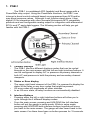
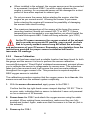
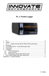
PSB-1 User Manual Warning! The Oxygen Sensor used in this device gets very hot in operation. Do not touch a hot sensor. Do not let a hot sensor touch a combustible surface. Do not use the sensor with or near flammable liquids or gases. Failure to heed these warnings may result in severe burns, explosions, fires, or other dangerous events. 1. PSB-1 ....................................................................................................... 2 1.1 Changing the PSB-1’s gauge face and/or bezel ............................. 3 2 Installation ................................................................................................ 4 2.1 Wiring............................................................................................... 4 2.1.1 Single Innovate Device Relay Wiring Instructions ....................... 5 2.2 Gauge Mounting and Routing ......................................................... 5 2.3 PowerSafe Relay ............................................................................. 6 2.4 MAP sensor ..................................................................................... 6 2.5 Wideband Oxygen Sensor Setup .................................................... 7 2.5.1 Oxygen Sensor Placement .......................................................... 7 2.5.2 Sensor Calibration ....................................................................... 8 2.5.3 Calibration Schedule ................................................................... 9 3 PSB-1 Setup............................................................................................. 9 3.1 Entering Setup Configuration .......................................................... 9 3.1.1 Configuration using PSB-1’s interface buttons ............................ 9 3.1.2 Configuration using the LM Programmer software .................... 10 3.2 Display Settings (Gauge Abbreviations)........................................ 10 3.3 RPM Settings (Gauge Abbreviations) ........................................... 10 3.4 Relay Settings (Gauge Abbreviations) .......................................... 11 4 Logworks 3 & LM Programmer Software Package ................................ 11 4.1 Download and Install the Logworks 3 Software ............................ 12 4.2 LM Programmer............................................................................. 12 4.2.1 Programming Analog Output ..................................................... 12 4.2.2 Advanced Analog Output Programming .................................... 13 4.2.3 Updating the Firmware .............................................................. 13 4.2.4 Changing Sensor Type .............................................................. 14 4.3 Logging data from your PSB-1 with LogWorks ............................. 14 Appendix A: Limited Warranty ....................................................................... 16 Appendix B: PSB-1 Error Codes and Troubleshooting Tips ......................... 17 11-0141 1. PSB-1 The PSB-1 is a wideband AFR (lambda) and Boost gauge with a PowerSafe relay output. Using the PowerSafe functions, the PSB-1 can interrupt a boost control solenoid based on programmed lean AFR and/or max boost pressure values. Although it can function stand alone, it has digital I/O for integration with other Innovate Motorsports MTS compatible products and one configurable analog output for integration with aftermarket ECU’s and 3rd party data loggers. The following section will help you get familiar with the PSB-1. 1. Channel Displays - The PSB-1 has four different displays modes that can be cycled through on the main screen with the left and right interface buttons. It can be configured to display A/F or pressure as primary channels or both A/F and pressure in both the primary and secondary channel viewports. 2. Status or Error display - The upper right hand viewport of the PSB-1 is reserved to display the status of the relay or any error codes that might be present. - O2 error codes will supersede all other statuses. - In an O2 error state, all relay functions are automatically disabled. 3. Interface Buttons - Pressing either the left or right interface buttons will allow you to cycle through the 5 different display modes. - From the main screen, pressing and HOLDING the left interface button will put the gauge in setup mode. While in setup mode, pressing and HOLDING both interface buttons together will move you back to the main screen. The gauge will also revert back to the main screen if no there have been no button presses for 15 seconds. 2 - - From the main screen, pressing and HOLDING both the left and right interface buttons will disable/enable Valet mode. If there are no other error codes on the status viewport of the screen, the PSB-1 will display “Valet”. From the Peak boost display, press and HOLD the right interface button to clear the stored peak boost value. 4. Shift Light - Illuminates when the trigger shift RPM is reached. 1.1 Changing the PSB-1’s gauge face and/or bezel 1. Lay the PSB-1 face down and remove the three #2 phillips screws from the outside rim of the back plate. 2. 3. Configure the gauge as desired by changing the gauge face and/or bezel. 4. Make sure every piece is positioned correctly using the locating tab and reassemble the gauge. 5. Reinstall the three #2 phillips screws verifying that the buttons are not binding on the gauge lens. 3 2 2.1 Installation Wiring The PSB-1 has 5 stripped wire leads: 1 Connect the RED wire to an isolated switched 12V source in your vehicle. A switched 12V source goes ON as soon as “key on” power is active. The circuit to which you will pull power from should be able to support a 3 amp draw. Make sure this connection is protected with a 5A fuse (not supplied.) Circuits that share power with the vehicle’s stereo, ignition system, ECU, lighting, or fuel pump should not be used. When in doubt, create an additional circuit using an automotive relay available at any automotive parts supplier. See the next section for a relay installation diagram. 2 The BLACK wire should be grounded to a solid ground source. The best possible ground source would be the battery ground (-) post. If other Innovate Motorsports devices are going to be daisy-chained along with the PSB-1, it is recommended that all devices be connected to a single ground point, ideally the battery ground (-) post. 3 Connect the WHITE wire to a headlight power wire (a wire that goes hot with 12V when the headlights are on). This enables the display to dim for better nighttime viewing. DO NOT CONNECT THIS WIRE TO THE HEADLIGHT DIMMING WIRE. Connection to this rheostat type of switch will cause the gauge to malfunction. If you chose not to utilize the dimming feature, connect the WHITE wire to ground. 4 Optionally, the YELLOW analog output can be connected to the analog input of other devices such as data loggers or standalone ECUs. If this 4 wire is not being used isolate and tape it out of the way. The default analog output configuration is 0V = 7.35 AFR and 5V = 22.39 AFR. 5 Optionally, the PURPLE wire can be connected to a tach signal to log engine RPM and to use the shift light function. A tach signal can be acquired from the negative lead of a coil, ECU, negative lead of an injector, or directly from the ignition box if running a multi-spark (i.e. MSD 6AL). Note: A tach signal can not be acquired from the negative lead of the coil on vehicles running CDI ignitions. For these applications use the negative lead of an injector or a tach adapter (if available for your model ignition). 2.1.1 Single Innovate Device Relay Wiring Instructions The relay diagram below is intended for use to power the gauge, it is not for the PowerSafe relay’s operation. 2.2 Gauge Mounting and Routing The PSB-1 gauge fits in any standard 2 1/16” (52mm) gauge pod. Mounting of the gauge should be done in such a manner that the cables are not being forcefully pulled and strained from the gauge itself. Route the sensor and 5 solenoid cables avoiding contact with the exhaust system and other vehicle components that could damage the cable. Also avoid routing the cables near ignition components or other sources of RF (radio frequency) and EMI (Electromagnetic interference) noise. 2.3 PowerSafe Relay The PowerSafe functions by intercepting one of the two boost control leads with the included relay. The relay breaks (opens) the circuit when the user defined conditions are exceeded. The circuit has continuity (closed) in it’s normal operating state. 1. Disconnect the battery negative (ground) lead. 2. Locate your boost controller solenoid and select one of the two wires. It is not critical which of the two single leads you intercept. 3. Cut the chosen wire leaving enough wire length on both ends to connect to the relay wires. 4. Solder and heat shrink one exposed end of the solenoid wires to the BLUE relay wire. Solder and heat shrink the other exposed end of the solenoid wire to the YELLOW relay wire. It is not critical which side of the intercepted solenoid wires connects to either of the blue or yellow relay wires. 5. Mount the relay in a suitable location away from high temperatures or near ignition components. 6. Route the relay cable through the firewall, to the gauge and connect to the 2 pin connector. 7. 2.4 MAP sensor 1. The MAP sensor MUST be installed with the hose fitting facing down. It is very important that the sensor be isolated from heat sources, mounted away from all ignition and/or other potential RF emitting sources, and protected against excessive vibration. The MAP sensor has two 1/8” holes that can be used to secure the sensor. Another viable option is to use double-sided mounting tape. 6 2. Locate a vacuum source on the intake manifold, after the throttle body and connect it to the hose barb on the sensor. Use the provided “T” and hose to make this connection if needed. To secure the hose use tie-wraps or hose clamps. 3. With the engine idling, confirm that you do not have any air/vacuum leaks. 2.5 Wideband Oxygen Sensor Setup 2.5.1 Oxygen Sensor Placement Optimum bung placement will vary from application to application, but using the guidelines below will ensure the longest sensor life with the most accurate readings. Using a bung is the preferred method for mounting the oxygen sensor in all applications. Weld the bung at least 24 inches after the turbocharger. Using a clock as reference, mount the bung between the 9:00 o’clock and 3:00 o’clock position. Welding the bung in the lower section of the exhaust pipe can result in sensor damage caused by condensation making contact with the sensor’s internal heating element. A 1” bung (provided in the kit) will best protect the sensor. When fully threaded, the sensor’s tip will sit flush with the inside of the exhaust piping, this does not adversely effect the readings. The bung should always be welded before the Catalytic Converter. Welding the bung after the catalytic converter will skew the readings toward lean. The skew in readings will vary with engine load and the efficiency of the catalytic converter. Leaded fuel and two stroke applications will reduce the sensor’s life. There are many other factors that dictate the sensor’s lifespan so it is impossible to predict total sensor longevity. Exhaust leaks, camshaft overlap, and open (shorty) exhausts will cause false lean readings at light engine loads. Typically, once the engine is under load and the exhaust gas volume increases, you will see accurate readings. 7 When installed in the exhaust, the oxygen sensor must be connected to a powered, functional PSB-1 (no error codes) whenever the engine is running. An un-powered sensor will be damaged in a short period of time when exposed to exhaust gas. Do not pre-warm the sensor before starting the engine, start the engine as you normal would. Allowing the sensor to pre-warm before starting the engine will increase the possibility of damaging the sensor from shock-cooling. The maximum temperature of the sensor at the bung (the sensor mounting location) should not exceed 500 oC or 900 oF. If these temperatures are exceeded in your application you should install the Innovate Motorsports HBX-1 heat sink bung extender. (p/n 3729.) As the O2 sensor measures the oxygen content of the exhaust gas to provide an accurate O2 reading, even a small pin-hole leak in a poorly welded sensor bung will effect the accuracy and performance of your O2 sensor. Remember, any deviation from the instructions provided for proper sensor installation will lead to inaccurate O2 readings. 2.5.2 Sensor Calibration Once the unit has been wired and a suitable location has been found for both the gauge and the sensor it is time to perform the sensor calibration. Innovate Motorsports’ ‘Direct Digital’ wideband measurement principal allows you to calibrate the sensor to compensate for sensor wear. This procedure takes just a few moments and it will ensure the most accurate readings throughout the oxygen sensor’s life. This procedure is required anytime a NEW oxygen sensor is installed. The calibration procedure requires that the oxygen sensor be in free air, this means removed from the exhaust system completely. 1. With the sensor disconnected, apply power to the PSB-1. Confirm that the top right-hand corner viewport displays “O2 E2.” This is an error code, indicating that no sensor is detected. Leave unit powered on for a minimum of 30 seconds. 2. Power down the PSB-1 and attach the oxygen sensor using the cable provided. When making these connections, make sure they are fully seated and locked. Again, make sure that the sensor is in free air (not in the exhaust). 3. Power up the PSB-1. 8 The PSB-1 will start warming up the sensor, this is indicated on top righthand corner viewport of the display by showing “O2 HTR.” After 30-60 seconds, the display will switch from “O2 HTR” and quickly flash “O2 CAL”, indicating that the sensor is being calibrated. The calibration procedure has completed and the system is now ready for use. Important: You can disconnect and reconnect the sensor and sensor cable for installation without losing your calibration. However, if you power up the PSB-1 without a sensor connected, your calibration will be reset (see step #1 above). 2.5.3 Calibration Schedule Turbo Application, daily driver (tuned rich) - Calibrate before installation of new sensor - Calibrate new sensor again after 3 month of use - Thereafter calibrate twice a year or every 10,000 miles, whichever comes first Race Application - Calibrate before first installation of new sensor - Calibrate once per race weekend 3 3.1 PSB-1 Setup Entering Setup Configuration The PSB-1 can be configured directly from the gauge itself or by connecting it to a computer with the LM Programmer software. 3.1.1 Configuration using PSB-1’s interface buttons 1. From the main screen, press and HOLD the left interface button to put the gauge in setup mode 2. Pressing either the left or right interface buttons will allow you to cycle through the 10 different setup parameters in the menu. 3. Once the desired setup parameter is displayed, press and HOLD the left interface button to make a change. Once the parameter’s configuration has been entered it will start flashing. 4. Make changes by using the left or right interface buttons. 5. Once in setup mode, pressing and HOLDING both interface buttons together will move you to the main screen. The gauge will revert back 9 to the main screen if no there have been no button presses for 15 seconds. 3.1.2 Configuration using the LM Programmer software Refer to chapter 4, Logworks 3 & LM Programmer Software Package to gain access to the software. 1. Connect the OUT port of the PSB-1 to the provided serial programming cable. Connect the other end of the serial programming cable to your computer. If your computer does not have a serial port, you can purchase a USB to Serial adapter from Innovate Motorsports (P/N 3733) or use any USB to serial adaptor that includes drivers. Make sure that nothing is connected to the IN port of the PSB-1 2. Power up the PSB-1. 3. Launch LM Programmer. The LM Programmer application can be launched from Start->Programs->LogWorks3->LM Programmer from the Windows task bar. Once you have completed your desired changes, press the Program button on the lower right on the software application. You will know that the PSB-1 has been programmed successfully when the Program button grays out. 3.2 Display Settings (Gauge Abbreviations) 1. MAP Units - Allows the gauge to display pressure in either inHG/PSI, kPa or BAR. Default setting is inHG/PSI 2. Wideband O2 Units (WB O2 Units) – Allows the gauge to display O2 units in either AFR or Lambda. Default setting is AFR. 3. Enable Wideband O2 (WB O2 State) – Allows the wideband to be disabled or enabled. Also indicates the sensor type used (sensor type can only be changed by connecting the PSB-1 to LM Programmer.) NOTE: If the wideband is disabled, the O2 sensor should be removed from the exhaust to avoid damaging it. Default setting is O2 enabled. 4. Fuel Type – Change to different fuel types when PSB-1 is setup to display in AFR. Default setting is Gasoline. 3.3 RPM Settings (Gauge Abbreviations) 1. Mode (RPM Mode) - Select how many pulses per rotation (ppr) based on your tach signal source. When setting the Mode using the 10 gauge interface, you will also see a real-time display of the RPM to ease the setup. Default is 1 pulse per rotation. 2. Scale (RPM Scale) – Select either 10230 or 20460 RPM scales. Default is 10230 3. Shift RPM – Set to desired RPM to trigger illumination of the shift light on the PSB-1. Default is 10230 RPM. 3.4 Relay Settings (Gauge Abbreviations) In an O2 error state, all relay functions are automatically disabled. 1. Boost Cut by Pressure (Boost Cut Press) - This is a safety trigger to cut boost at a desired maximum manifold pressure. When the safety Boost Cut by Pressure is triggered, the PSB-1 will display “B Cut” on the upper right hand corner viewport and the relay will interrupt all solenoid control and boost will default to spring pressure. Default setting is 8 PSI. 2. Boost Cut by AFR – This is a safety trigger to cut boost by a defined AFR. There are two setup parameters to trigger this safely cut: Start Pressure (AFR Start Press) and AFR Cut. Start Pressure (AFR Start Press) is the minimum manifold absolute pressure where the safety cut will become active. AFR Cut is the defined lean A/F that will trigger the safety cut. When the Boost Cut by AFR is triggered, the PSB-1 will display “O2 Cut” on the upper right hand corner and the relay will interrupt all solenoid control and boost will default to spring pressure. . Default setting is 13 AFR. 3. Valet ON/OFF – When configured from the gauge, this setting is accessed from the main screen. Press and HOLD both the left and right interface buttons, this will disable/enable relay control. When Valet mode is active, the relay will interrupt all solenoid control and boost will default to spring pressure. If there are no other error codes on the status viewport of the screen, the PSB-1 will display “Valet” when active. In LM Programmer, use the ‘Valet Mode OFF’ checkbox to turn the solenoid control ON/OFF. Default setting is Valet mode OFF. 4 Logworks 3 & LM Programmer Software Package The PSB-1 can be connected directly to your Windows computer to log and analyze data with the Logworks software or to configure with LM Programmer. The software is a free download on the Innovate Motorsports’ support section of the website. 11 4.1 Download and Install the Logworks 3 Software 1. Open your web browser and go to the following URL: http://www.innovatemotorsports.com/support.php 2. The LogWorks 3 software download will be the very first thing on the page under the heading Software, click the link to download the software. 3. Double click on the Logworks 3 installer previously downloaded from the support section of the Innovate Motorsports web site. 4. The installer will start, follow the prompts to install the software. 5. Once the software has been installed, the LogWorks software, LM Programmer, manuals, and tools can then be located by navigating through Start->Programs->LogWorks3. 4.2 LM Programmer LM Programmer is used to configure settings on your PSB-1. 1. Connect the OUT port of the PSB-1 to the provided serial programming cable. Connect the other end of the serial programming cable to your computer. If your computer does not have a serial port, you can purchase a USB to Serial adapter from Innovate Motorsports (P/N 3733) or use any USB to serial adaptor that includes drivers. Make sure that nothing is connected to the IN port of the PSB-1 2. Power up the PSB-1. 3. Launch LM Programmer. The LM Programmer application can be launched from Start->Programs->LogWorks3->LM Programmer from the Windows task bar. 4.2.1 Programming Analog Output Connect the PSB-1 to the computer and launch LM Programmer. Select the Analog Output tab. The analog output configuration screen shows voltage versus Lambda for the analog output. The graph display is automatically scaled to the selected voltages values. The configuration screen allows the user to specify a minimum and maximum lambda or A/F value to a corresponding voltage range. By selecting the ‘use Air-Fuel-Ratio’ button you can change the displayed unit of measure for mixture by AFR instead of Lambda. This does not change the programming, only the unit of measure displayed in the configuration screen. Click the ‘Program’ button to upload your modified A/F or lambda scaling data into the PSB-1. Once the unit has been programmed, the ‘Program’ button will grey out. Factory Programmed Default: 12 The analog output by default is programmed to output between 0V at 7.35 AFR to 5.0V at 22.39 AFR. 4.2.2 Advanced Analog Output Programming The ‘Advanced’ button allows the user to set the analog out update speed and the voltage output during sensor Warm-up and error conditions. The factory defaults of the analog outputs update 1/12 of a second. The default voltage output is set at 0 volts for both the Warm-up and error conditions. When setting the PSB-1 to the slower response speed settings, the measured mixture data will be averaged over the response time setting before being sent via the analog output. 4.2.3 Updating the Firmware Do not update the firmware if the versions are the same. A firmware update should only be necessary if there has been a new release that specifically fixes a problem that you are experiencing with the controller. 1. Connect the PSB-1 to the computer and launch LM Programmer. 2. Once connected, LM Programmer will display the current version of the firmware that is installed in the PSB-1. Do not flash the firmware if the versions are the same. 3. On the ‘Info’ tab of LM Programmer you will see a button labeled “Update Firmware,” click this button. 4. Select the firmware file with the dld extension. If there have been revisions to the firmware, you will find them available for download from the Support section of the Innovate Motorsports web site. 5. The software will now prompt you to confirm that you wish to overwrite the firmware currently on your PSB-1. 6. Click OK, the gauge of the PSB-1 will go blank. DO NOT power off or disconnect the PSB-1 from the computer until the firmware progress 13 screen completely disappears. Once finished, you may disconnect the unit from the computer and exit out of the software. 4.2.4 Changing Sensor Type The PSB-1 is multi sensor compatible with the Bosch LSU 4.2 and 4.9 sensors. In order to go from one sensor type to another the PSB-1 must be connected to the LM Programmer software and the appropriate sensor type must be selected. The “Sensor Type to use” setting can be found in the ‘Info’ tab when LM Programmer connects to the PSB-1. Once the sensor type is changed a sensor calibration must be performed with the sensor outside of the exhaust (see Sensor Calibration chapter.) 18ft Sensor Cable P/N 3ft 8ft LSU 4.2 3843 3810 3828 LSU 4.2 3737 LSU 4.9 3890 3887 3889 LSU 4.9 3888 Sensor P/N Note: All sensor cables for the LSU 4.9 are easily identified by a ‘4.9’ marking molded on the sensor connector side. Use the appropriate sensor cable for the sensor type as each sensor has a different style connector. Spliced cable can not only affect the wideband’s performance but in worst cases it can damage the sensor and/or controller. Selecting the wrong sensor type to the sensor being used will not only give you erroneous readings and/or errors. It can also permanently damage the sensor. 4.3 Logging data from your PSB-1 with LogWorks Logworks is an invaluable tool to help setup your PSB-1. The PSB-1 has four channels of sensor data built in for the tuning of not only your desired boost levels, but also a safe operating air fuel ratio for your engine. These channels are: 1. Wideband O2: Units in AFR or Lambda 2. RPM 3. Boost 4. Relay State 14 1. Connect the OUT port of the PSB-1 to the provided serial programming cable. Connect the other end of the serial programming cable to your computer. If your computer does not have a serial port, you can purchase a USB to Serial adapter from Innovate Motorsports (P/N 3733) or use any USB to serial adaptor that includes drivers. Make sure that nothing is connected to the IN port of the PSB-1. Power up the PSB-1. 2. Launch LogWorks. The LogWorks application can be launched from Start->Programs->LogWorks3->Logworks3 from the Windows task bar. 3. Once LogWorks launches go to File->Connect. You will be prompted to connect to the serial COM port. Select the COM port the device is connected to and then click Connect. 4. You will now see live data streaming from the PSB-1. 5. To start recording go to File->New Realtime Log or, in the Toolbar, click on the Tool. 15 Appendix A: Limited Warranty LIMITED WARRANTY Innovate stands behind the quality of its products. Innovate makes the following warranty to purchasers of its products: All new Innovate products carry a one year warranty from the date of purchase. If proof of purchase cannot be provided, warranty will be determined by date of manufacture. When Warranty Void This warranty shall terminate and Innovate shall have no obligation pursuant to it if (i) your Innovate product has been modified or repaired in a manner not previously authorized by Innovate in writing, (ii) the identification markings on your Innovate product have been removed, defaced, or altered; (iii) your Innovate product was subjected to accident, abuse, shipping damage, or improper use; (iv) your Innovate product was not used or configured as specified in the product manual; or (v) your Innovate product was subjected to operating conditions more severe than those specified in the product manual. Exclusions From This Warranty Oxygen Sensors are excluded from this warranty. Repairs Under This Warranty In the unlikely event that your Innovate hardware product should prove defective during the warranty period, contact Innovate Customer Support at http://www.innovatemotorsports.com/rma_form.php for a return material authorization (RMA). Products returned for service must be securely packed to prevent damage and shipped charges pre paid, along with proof of purchase and the return material authorization number, to the Innovate repair location as instructed by Customer Service. Innovate within a reasonable amount of time from its receipt of your product so shipped, will ship to you, at its option, the repaired product or a new or reconditioned product of comparable or greater specified functionality. All repaired or replacement products shall be warranted for the remainder of the original product warranty. Disclaimer INNOVATE MAKES NO OTHER EXPRESS OR IMPLIED WARRANTY WITH RESPECT TO YOUR INNOVATE PRODUCT OTHER THAN THE LIMITED WARRANTY SET FORTH ABOVE. No Innovate dealer, agent, or employee is authorized to make any modification, extension, or addition to this warranty, unless enforceable or unlawful under applicable law, INNOVATE DISCLAIMS ALL IMPLIED WARRANTIES, INCLUDING THE IMPLIED WARRANTIES OF MERCHANTABILITY, NONINFRINGEMENT, AND FITNESS FOR A PARTICULAR PURPOSE, AND THE LIABILITY OF INNOVATE, IF ANY, FOR DAMAGES RELATING TO ANY ALLEGEDLY DEFECTIVE PRODUCT SHALL UNDER ANY TORT, CONTRACT, OR OTHER LEGAL THEORY BE LIMITED TO THE ACTUAL PRICE PAID FOR SUCH PRODUCT AND SHALL IN NO EVENT INCLUDE INCIDENTAL, CONSEQUENTIAL, SPECIAL, OR INDIRECT DAMAGES OF ANY KIND EVEN IF INNOVATE IS AWARE OF THE POSSIBILITY OF SUCH DAMAGES. Some states do not allow limitations on how long an implied warranty lasts or the exclusion or limitation of incidental or consequential damages, so the above limitations or exclusions may not apply to you. 16 Appendix B: PSB-1 Error Codes and Troubleshooting Tips Error Code Error 1 Error 2 Error 3 Error 4 Error 5 Error 6 Error Message Heater circuit shorted Heater circuit open Likely Root Cause Fix Short in sensor Replace sensor. 1. Damaged sensor cable or sensor. 2. Sensor connector not fully seated and locked into position. Pump cell 1. Short in sensor circuit shorted cable 2. Short in sensor 3. Sensor calibration incorrect Pump cell 1. Damaged sensor circuit open cable or sensor. 2. Connectors not fully seated 3. Sensor calibration incorrect Reference cell 1. Short in sensor circuit shorted cable 2. Short in sensor Reference cell 1. Damaged sensor circuit open cable or sensor. Error 7 System error Error 8 Sensor Timing error (typically a damaged sensor). 2. Connectors not fully seated System error 1. Sensor over-heating or over-cooling (error condition only occurs at wide open throttle ) 2. Sensor is damaged Error 9 Supply Voltage too low Supply voltage too low for sensor regulation 1. Verify that all sensor connectors are fully seated and locked into position. 2. Replace sensor 3. Replace sensor cable. 1. Replace sensor cable. 2. Replace sensor. 3. Perform sensor recalibration. 1. Verify that all sensor connectors are fully seated and locked into position. 2. Perform sensor calibration 3. Replace sensor cable. 4. Replace sensor. 1. Replace sensor cable. 2. Replace sensor. 1. Verify that all sensor connectors are fully seated and locked into position. 2. Replace sensor. 3. Replace sensor cable. Reboot PSB-1 by cycling power. 1. Perform sensor calibration. 2. Move sensor bung as far downstream as possible. 3. Add an HBX-1 (p/n 3729) to isolate the sensor from the pipe. 4. Replace sensor. 1. Verify you have 12V at your power source and the circuit can support a 3 amp draw. In an O2 error state, all relay functions are automatically disabled. 17