1
Mitsubishi Electric Q Series
PLC Ladder Monitor
Operation Manual
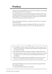
Preface
Thank you for purchasing Pro-face's PLC Ladder Monitor Add-on Kit for the Mitsubishi Electric Q Series PLC. This
manual ("Mitsubishi Electric Q Series PLC Ladder Monitor Operation Manual") explains how to operate the PLC ladder
monitor featuer and device monitor featuer while using Pro-face's GP2000 Series operator interfaces.
Be sure to read this manual carefully to understand how to correctly use your PLC Ladder Monitor Add-on Kit.
Be sure to keep this manual close at hand for easy reference.
Notice
1.
The copyrights to all programs and manuals included in the "PLC Ladder Monitor Add-on Kit for the Mitsubishi Electric Q Series PLC" (hereinafter referred to as "this product") are reserved by the Digital Electronics
Corporation. Digital grants the use of this product to its users as described in the "Software Operating and
License Conditions" section. Any actions violating the above-mentioned conditions are prohibited by both
Japanese and foreign regulations.
2.
The contents of this manual have been thoroughly checked. However, if you should find any errors or omissions in this manual, please contact your local representative and inform them of your findings.
3.
Please be aware that Digital Electronics Corporation shall not be held liable by the user for any damages,
losses, or third party claims arising from the uses of this product.
4.
Differences may occur between the descriptions found in this manual and the actual functioning of this product. The latest information about this product is provided in the accompanying data files (i.e. Readme.txt
files, etc.) and/or separate documents. Please consult these sources as well as this manual prior to use.
5.
Even though the information contained in and displayed by this product may be related to intangible or intellectual properties of the Digital Electronics Corporation or third parties, the Digital Electronics Corporation
shall not warrant or grant the use of said properties to any users and/or other third parties.
All product names used in this manual are trademarks or registered trademarks of their respective owners.
(c) 2004 Digital Electronics Corporation. All rights reserved.
1
Table of Contents
Preface...................................................................................................................... 1
Notice ........................................................................................................................ 1
Table of Contents ...................................................................................................... 2
Documentation Conventions ..................................................................................... 3
Related Units............................................................................................................. 4
CHAPTER 1 Overview and Setup
1.1 Overview......................................................................................................... 1-2
1.1.1 System Design......................................................................................................1-3
1.1.2 Operation Mode ....................................................................................................1-4
1.2 Installation Procedure ..................................................................................... 1-5
CHAPTER 2 Operation
2.1 Installation....................................................................................................... 2-2
2.1.1 CD Installation.......................................................................................................2-2
2.1.2 Project File Creation/Running ...............................................................................2-2
2.1.3 Device Monitor Registration..................................................................................2-2
2.1.4 Project Transfer ....................................................................................................2-4
2.1.5 Copy Boot File to a CF Card.................................................................................2-4
2.1.6 Insert the CF Card into the GP .............................................................................2-4
2.1.7 Connect the GP to the PLC ..................................................................................2-4
2.2 PLC Ladder Monitor Feature Startup.............................................................. 2-5
2.2.1 Via the Menu Bar ..................................................................................................2-5
2.2.2 Turning the Extended Special Relay Area ON......................................................2-6
2.3 Screen Names ................................................................................................ 2-7
2.3.1 Main screen ..........................................................................................................2-7
2.3.2 Ladder Diagrams ..................................................................................................2-7
2.4 Screen Operation............................................................................................ 2-8
2.4.1 PC Read ...............................................................................................................2-9
2.4.2 Device Monitor .................................................................................................... 2-11
2.4.3 Search Feature ...................................................................................................2-12
2.4.4 Comments...........................................................................................................2-15
2.5 Usage Restrictions........................................................................................ 2-16
2.5.1 Notation...............................................................................................................2-16
CHAPTER 3 Errors
3.1 Error Messages .............................................................................................. 3-2
2
Documentation Conventions
This manual uses the following symbols and terminology.
Indicates a potentially damaging action or dangerous situation that
could result in abnormal equipment operation or data loss.
Screen editor
software
PLC
*
Indicates GP-PRO/PB III for Windows
Indicates a Programmable Logic Controller (Also known as
sequencer).
Indicates useful or important supplemental information.
Provides useful or important supplemental information.
SEE
Indicates related information.
3
Related Units
Related PLC units
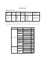
The table below lists the PLC units that can be used with the Add-on Kit.
Manufacturer
Mitsubishi
Electric
Series
Name
Q Series
CPU
Link I/F or
CPU direct
connection
Connection Cable
Device Type in
Screen Editor
CPU direct
connection
Mitsubishi Electric’s
QC30R2
(Requires 9-pin / 25pin conversion
adapter) or
Diatrend’s
DQCABR2-H
Mitsubishi Electric
MELSEC-Q(CPU)
Q02
Q02H
Q06H
Q12H
Q25H
Related GP units
The table below lists the GP units that can be used with the Add-on Kit software.
Also, to use the Cache Function on a GP/GLC unit, the unit's revision code must be the same as or higher than those listed
below.
Series Name
Unit Name
Model No.
Rev.
GP-2401HT
GP2401H-TC41-24V
B-3
GP-2400T
GP2400-TC41-24V
H-2
GP-2401T
GP2401-TC41-24V
-2
GP2500-TC11
G-2
GP2500-TC41-24V
C-2
GP-2500S
GP2500-SC41-24V
A-2
GP-2500L
GP2500-LG41-24V
B-2
GP-2501T
GP2501-TC11
D-2
GP-2501S
GP2501-SC11
E-2
GP-2501L
GP2501-LG41-24V
-2
GP2600-TC11
F-2
GP2600-TC41-24V
C-2
GP-2601T
GP2601-TC11
-2
GLC2400T
GLC2400-TC41-24V
F-2
GLC2500-TC41-24V
All Rev.
GLC2500-TC41-200V
All Rev.
GLC2600-TC41-24V
E-2
GLC2600-TC41-200V
All Rev.
GP-2500T
GP-2000 Series
GP-2600T
GLC2500T
GLC2000 Series
GLC2600T
4
IT2400 Type A
IT2400-TC41-GP
C-2
IT2400 Type B
IT2400-TC41-GLC
E
IT Series
Related Screen Editor Software
GP-PRO/PBIII for Windows Ver. 5.0 or later.
When using this product with GLC2000 series or IT2400 Type B, please use GP-PRO/PBIII C-Package03
Service Pack 2 (Ver.7.20) or later.
5
Memo
6
1
Overview and Setup
1.1 Overview
1.2 Installation Procedure
1-1
Mitsubishi Electric Q Series PLC Ladder Monitor Operation Manual
1.1 Overview
The PLC Ladder Monitor software enables you to read PLC ladder programs and display them as ladder diagrams on the GP unit.
This software operates on the GP unit and the software’s boot file is stored in the GP unit’s CF Card.
The PLC Ladder Monitor Add-on Kit has the following features:
•
Displays PLC ladder programs as ladder diagrams.
•
Displays power (ON) lines using bold lines.
•
Displays the designated step number.
•
Displays circuit data including the designated device address.
•
Displays circuit data in which the designated device address is included in the output instruction.
•
Displays ladder program comments.
•
Calls the Device Monitor feature.
•
Use the Device Monitor feature to set, reset or change the value of an arbitrary device.
• The Device Monitor feature is not explained in this manual. For information on how to operate
this feature,
SEE
1-2
GP-PRO/PBIII for Windows Device/PLC Connection Manual (Included with the screen editor software).
Chapter 1 Overview and Setup
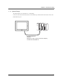
1.1.1 System Design
The GP and the PLC are connected in a 1:1 relationship.
Connect one end of the cable to the GP unit’s serial interface port, and the other end to the PLC unit’s CPU
module RS-232C port.
Mitsubishi Electric's
QC30R2
(Requires a 9-pin / 25-pin conversion adapter)
or Diatrend's DQCABR2-H
1-3
Mitsubishi Electric Q Series PLC Ladder Monitor Operation Manual
1.1.2 Operation Mode
The PLC Ladder Monitor feature enables you to:
(1)
Read PLC ladder programs and display them on the GP unit, via [Ladder Monitor].
(2)
Monitor/change arbitrary PLC device addresses, via [Device Monitor].
After [Ladder Monitor] is started, the GP switches to ladder monitor mode. [Device Monitor] mode can be
used when the GP is in ladder monitor mode, as well as in online (RUN) mode.
Online Mode (RUN mode)
Device
Monitor
GP
Features
Menu Bar
Device Monitor
(3-point push type menu)
Offline
Monitor
Reset
Ladder Monitor Mode
(Offline Mode)
Offline
Mode
Ladder
Monitor
RUN
GP
Reset
Device
Monitor
END
Return to Offline Mode
• The GP unit will be reset if you switch from online mode to ladder monitor mode.
1-4
Chapter 1 Overview and Setup
1.2 Installation Procedure
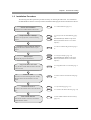
The following flowchart explains the procedure necessary for installing the Add-on Kit. It is assumed that
GP-PRO/PB III for Windows is already installed, and that the ladder program has been transferred to the PLC.
Add-on Kit Installation
SEE
2.1.1 CD Installation (page 2-2)
Install the PLC Ladder Monitor Add-on Kit.
Project Creation / Startup
Create a new project file, or start an existing
project.
SEE
SEE
Manual (Included with the screen editor
software)
Registering Device Monitor feature
Register the Device Monitor feature in your
project.
SEE
2.1.3 Device Monitor Registration (page 22)
SEE
2.1.4 Project Transfer (page 2-4)
Send project
Transfer the project to the GP unit.
SEE
Insert CF Card
Insert the CF Card containing the PLC Ladder
Monitor feature into the GP unit's CF Card
socket.
Connect GP to PLC
Connect a data transfer cable to the GP and the
PLC
Start Ladder Monitor
Turn the GP and PLC units ON, and start the
Ladder Monitor feature.
GP-PRO/PB III for Windows Operation
Manual (Included with the screen editor
software)
Copy boot file to CF Card
Copy the PLC Ladder Monitor feature boot file
to the CF Card.
2.1.2 Project File Creation/Running (page
2-2)
GP-PRO/PB III for Windows Operation
SEE
SEE
2.1.5 Copy Boot File to a CF Card (page 24)
2.1.6 Insert the CF Card into the GP (page
2-4)
SEE
1.1.1 System Design (page 1-3)
SEE
2.1.7 Connect the GP to the PLC (page 2-4)
SEE
2.2 PLC Ladder Monitor Feature Startup
(page 2-5)
1-5
Mitsubishi Electric Q Series PLC Ladder Monitor Operation Manual
Memo
1-6
2
Operation
2.1 Installation
2.2 PLC Ladder Monitor Feature Startup
2.3 Screen Names
2.4 Screen Operation
2.5 Usage Restrictions
2-1
Mistubishi Electric Q Series PLC Ladder Monitor Operation Manual
2.1 Installation
Please perform the following installation procedure prior to using the PLC Ladder Monitor feature.
2.1.1 CD Installation
In Windows Explorer, double-click on the CD’s Setup.exe file to start the installer program. Follow the
installer program’s directions.
• Prior to running the installer program, GP-PRO/PB III for Windows Ver. 5.0 or
later screen editor software must be installed on your system.Refer to the section
of the GP-PRO/PBáV for Windows Setup Guide that relates to your unit's OS
2.1.2 Project File Creation/Running
Create a new project file, or run an existing project file.
For project file details,
SEE
GP-PRO/PB III for Windows Operation Manual (Included with the screen editor software)
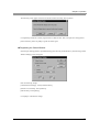
2.1.3 Device Monitor Registration
Register the Device Monitor feature in your project.
Starting from the screen editor software’s main screen, the procedure for registering the Device Monitor feature is explained below.
Registering the Device Monitor screen
Select the [Screen / Setup] menu’s [Device Monitor] feature.
Click [Add] to register the feature.
• To register the Device Monitor feature, at least 90KB of free GP space must be available. Therefore, after sending your project to the GP unit, be sure to check that at least 90KB of space is
remaining for this feature.
You can check the amount of GP memory used by your project via the Project Manager's
[Project] -> [Property] screen.
2-2
Chapter 2 Operation
The following screen appears if the Device Monitor feature has already been registered.
Click [Delete] to delete the currently registered Device Monitor data. Then, select [Screen / Setup] menu's
[Device Monitor], and click [Add] to register the feature again.
Registering the Global Window
Select the [GP Settings] feature's [Extended Settings] tab, and click [Global Window]. The following [Global
Window Settings] screen will appear.
Enter the following settings:
[Global Window Settings] - Select [Global Window].
[Window Access Mode] - Select [Indirect].
[Data Format] - Select [Binary]
Click [OK] to confirm these settings.
2-3
Mistubishi Electric Q Series PLC Ladder Monitor Operation Manual
2.1.4 Project Transfer
Next, transfer the project to the GP unit.
For project transfer details,
SEE
GP-PRO/PB III for Windows Operation Manual (Included with the screen editor software).
2.1.5 Copy Boot File to a CF Card
Insert a CF Card into your PC's CF Card reader and copy the Ladder Monitor boot file to the CF Card's root
directory.
The boot file is located in GP-PRO/PB III for Windows screen editor software's [PROTOCOL] folder.
Mitsubishi Electric's Q Series Ladder Monitor boot file filename: MEL_QP.SYS
To copy this program to a CF card, the card must have at least 2MB or more free space.
2.1.6 Insert the CF Card into the GP
Remove the CF Card from your PC's card reader and insert it in the GP unit's CF Card socket.
For CF Card socket insertion details,
SEE
Your GP unit User Manual (Separately sold).
2.1.7 Connect the GP to the PLC
Connect the data transfer cable between the GP and the PLC.
For cable connection details,
2-4
SEE
1.1.1 System Design (page 1-3)
SEE
GP-PRO/PB III for Windows Device/PLC Connection Manual (Included with the screen editor software)
Chapter 2 Operation
2.2 PLC Ladder Monitor Feature Startup
Either of the following two methods can be used to start the PLC Ladder Monitor feature.
2.2.1 Via the Menu Bar
(1)
To call up the GP screen’s Menu Bar, simultaneously press the areas marked by (i), (ii) and (iii) (See
below)
ii
iii
(2)
i
After the Menu Bar appears, select [MONITOR].
• If the Device Monitor feature has not been registered correctly, the [MONITOR] button will not
be displayed in the Menu Bar.
SEE
(3)
2.1.3 Device Monitor Registration (page 2-2)
[Menu] screen is displayed,touch the [Ladder Monitor] button.
2-5
Mistubishi Electric Q Series PLC Ladder Monitor Operation Manual
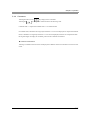
2.2.2 Turning the Extended Special Relay Area ON
Use a bit switch etc. to turn ON the GP internal memory's extended special relay LS2078's bit 1. This will
start up the PLC Ladder Monitor feature
.
15
....
3
2
1
0
LS2078
}
Reserved
Reserved
1:Start Ladder Monitor
Reserved
1:Read out cache data
Bit 1:Turning this bit ON starts the Ladder Monitor. The Ladder Monitor menu will not appear.
Bit 3:Immediately after the Ladder Monitor starts, turning this bit ON displays the ladder program
cached in the CF card. When using Bit 3, be sure to turn Bit 1 ON at the same time.
(cf. “Related Units” - “Related GP Units”)
If there is no cache data on the CF card, simply turning Bit 1 ON will read out the current data.
* Prior to using the Cache feature, the data must be read into a PC one time.
• Bits other than bit 1 are reserved. Do not write data to any of these bits.
2-6
Chapter 2 Operation
2.3 Screen Names
The following sections explain PLC Ladder Monitor screen layout.
2.3.1 Main screen
The PLC Ladder Monitor's main screen contains the following information.
Power Lines
Power Lines
Step Number, Label
Ladder Diagram, Ladder Data, Comments
Error Display Area
The number of rows that can be displayed on the screen varies depending on the comment mode. There are
three comment modes
•
No comment mode................................(11 contacts + 1 FUNC instruction) x 8 rows
•
Comment mode.....................................(11 contacts + 1 FUNC instruction) x 3 rows
•
Compressed comment mode.................(11 contacts + 1 FUNC instruction) x 5 rows
For details regarding comments,
SEE
2.4.4 Comments (page 2-15)
2.3.2 Ladder Diagrams
Types of ladder diagram screen data are shown below.
Step Number
Current Value
Device Comment
2-7
Mistubishi Electric Q Series PLC Ladder Monitor Operation Manual
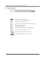
2.4 Screen Operation
The following information explains how to operate the Ladder Monitor screen.
.
Quits the PLC Ladder Monitor software.
The GP unit is reset and switches to ONLINE mode.
Reads in the PLC’s ladder programs.
Switches the style of data display between decimal and hexadecimal.
Starts the Device Monitor feature.
The [Monitor MENU] will appear.
Calls up the [Search Menu] to search for ladder program data.
Changes the device comment display format.
Scrolls through the ladder diagram one row at a time.
Scrolls through the ladder program one page at a time.
2-8
Chapter 2 Operation
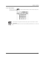
2.4.1 PC Read
Touching the main screen's
key displays the [Select Ladder File] screen.
.
.
Select the source of the ladder program.
The selected drive will be displayed in the screen top section’s [LD:] area.
Select from where the comment is to be read.
The selected drive will be displayed in the screen top section's [CMT:] area.
Reads in selected ladder program data, up to its END instruction.
Reads in all selected ladder program data.
Touch the ladder program to be read. A * mark is displayed to the left of the ladder program you selected.
Touching the ladder program again will cancel the selection.
Similarly, touch the comment to select it.
• You cannot select and read only a comment file.
2-9
Mistubishi Electric Q Series PLC Ladder Monitor Operation Manual
Searching Drives for Data
Follow the procedure outlined below to search for the ladder program's drive, and display only drives that
contain files.
•
Sequence program search
PG -> SRAM -> FLASH -> Internal RAM -> Internal ROM -> CACHE
•
Comment file search
PG -> SRAM -> FLASH -> Internal RAM -> Internal ROM -> CACHE -> CF
[CACHE]
- For a Sequence Program (cf. “Related Units” - “Related GP Units”)
When the Ladder Program is read out from "PG", "SRAM", "FLASH", "RAM", or "ROM", the data
("MEL_QP.CCH") is stored in [LADMON] folder of the CF card. With "CACHE", the ladder program stored
in the CF card is read out and displayed. Since no communication is being performed with the PLC, this readout is very fast. If CACHE is not available, the word "CACHE" will not be displayed. The ladder logic information shown by CACHE is for the previously read-out PLC ladder logic data. If the PLC's ladder logic data
has been changed or updated, or if the PLC has been changed, be sure to read out the latest ladder logic data
from the PLC
* Be sure the CF card used has 2MB or more free space.
- For a Comment file
When the comment file is read out from "PG", "SRAM", "FLASH", "RAM", or "ROM", the data
("***.QCD") is stored in [LADMON] folder of the CF card. With "CACHE", the comment file stored in the
CF card is read out and displayed.
* Be sure the CF card used has 2MB or more free space.
[CF]
- For a Comment file only
Comment file data (*.WCD) of a project created using the Mitsubishi Electric Corporation programming tool
"GX Developer" is read out from a CF card. Since readout of PLC data is not performed, this data is read out
quickly. Prior to performing this, be sure to create the [LADMON] folder in the CF card and copy the comment file (*.WCD) to this folder.
2-10
Chapter 2 Operation
2.4.2 Device Monitor
Touching the main screen's
key displays the [Monitor MENU]. The Device Monitor feature allows
you to monitor PLC devices.
• This manual does not explain Device Monitor feature operation or related details. For Device
SEE
Monitor details,
GP-PRO/PB III for Windows Device/PLC Connection Manual (Included with the screen editor software)
2-11
Mistubishi Electric Q Series PLC Ladder Monitor Operation Manual
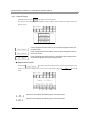
2.4.3 Search Feature
Touching the main screen's
key displays the [Search Menu].
This screen is used to designate the step number or device address of the circuit that will appear at the top of
the main screen.
Used to designate the step number of the circuit that will appear at the top of
the main screen.
Used to designate the device address of the circuit that will appear at the top
of the main screen.
Used to designate the output instruction containing the device address of the
circuit that will appear at the top of the main screen.
Step Numbers Search
Touching the
key displays the [Search Step] screen, which is used to designate a step
number. Use the screen's numeric keys (1 to 0) to enter a step number, and press
search.
Searches for and displays the ladder program's first step number.
Searches for and displays the ladder program's last step number.
2-12
to start the
Chapter 2 Operation
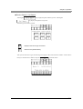
Device Search / Coil Search
Touching the
key displays the [Search Device] screen. Touching the
key displays the [Search Coil] screen.
Select the type of search to perform.
Displays other device type characters.
Returns to the [Search Menu].
After you select the device type, the following screen appears. Here, enter the device address. Use the character keys to enter the device address, and press
to start the search.
2-13
Mistubishi Electric Q Series PLC Ladder Monitor Operation Manual
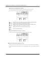
Searching for the designated device address
The circuit is displayed with the designated device address at the top of the main screen.
Next, a screen that enables you to search for identical device addresses is displayed.
Starting from the current ladder rung, searches backward for identical device
addresses, until the first row of the program is reached.
Starting from the current ladder rung, searches forward for identical device
addresses, until the last row of the program is reached.
Exits the search feature and returns to the main screen.
Returns to the [Search Menu].
When the designated device address is not found
The following screen is displayed when the device address search is unsuccessful.
Using a double-touch to search for a coil
When you touch the device address displayed on the main screen twice in succession, the output instruction
containing the designated address appears at the top of the main screen. This is similar in function to the coil
search.
2-14
Chapter 2 Operation
2.4.4 Comments
Touching the main screen's
Touching the
key displays device comments.
key changes the comment mode in the following order.
Comment mode -> compressed comment mode -> No comment mode
In comment mode, a maximum of 5 single-byte characters x 3 rows can be displayed. In compressed comment
mode, a maximum of 5 single-byte characters x 3 rows can be displayed (Characters are compressed to half
the original length). To display all comments, please use the Comment zoom feature.
Comment zoom feature
Touching a comment in the main screen will display that comment's entire text in the main screen's lower left
corner.
2-15
Mistubishi Electric Q Series PLC Ladder Monitor Operation Manual
2.5 Usage Restrictions
2.5.1 Notation
•
When monitoring bit devices used in a FUNC instruction, dividing the bit address by 16 calculates the
word address.
•
For a circuit, the maximum number of rows that can be displayed is 25. If the circuit contains more than
25 rows, rows from the 26th row will be omitted, and only the first 25 rows will be displayed. Also, when
searching for a device, if an abbreviation has been used for the device, when it is found, the device itself
will not be displayed, however, the start of the circuit that contains the device will be shown
•
Contacts, coils and frames through which power flows are indicated by bold (thick) lines. However, lines
connecting two contacts are displayed normally.
•
The main screen is displayed at the GP unit's center at 640 x 400 resolution. Blank space may be displayed
at the top, bottom, left or right corners of the screen, depending on the PLC model used.
2-16
3
Errors
3.1 Error Messages
3-1
Mistubishi Electric Q Series PLC Ladder Monitor Operation Manual
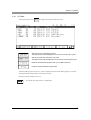
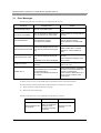
3.1 Error Messages
The following table lists errors that can occur when using the CF Card.
Message
Possible Cause
Solution
CF Card switch is OFF
The lid of CF Card is open.
Check whether the lid of CF card is
open.
CF Card is not installed
The CF Card has not been inserted
into the GP unit’s CF Card socket.
Check whether CF card is inserted
correctly.
CF Card Data Error
CF card data is unusual.
CF card is not formatted.
Check whether the contents of CF
card can be read correctly.
Check whether CF card is formatted.
Cannot read from CF Card
Cannot read the file from CF Card.
CF card was extracted during reading.
Check whether a file required for a
ladder monitor exists. It checks
whether CF card is inserted correctly.
Cannot write to CF Card
Cannot Write to file on the CF Card.
CF card was extracted during writing.
Availability of CF card is insufficient.
Check whether CF card is inserted
correctly.
Check whether the capacity of CF
card is vacant.
A file is not found
System file of a ladder monitor does
not exist.
Check whether a MEL_QP.SYS file
exists in CF card.
Ladder error *1
The read data was not convertible
for the ladder figure.
A cable is extracted during read-out
of a ladder.
Check whether there is any ladder
command to which the ladder monitor does not correspond.
Check whether a cable with PLC is
correct, and PC read-out is performed again.
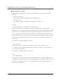
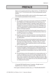
*1 When a circuit error occurs, the rudder display and reference after it cannot be performed.
The error message is detected when either of the following two conditions are satisfied.
(1)
When screens are changed to display a new page.
(2)
When a file's data is read again.
Solutions to the above errors vary depending on when the error occurred.
3-2
Error Occurrence
Internal Processing
When reading the ladder program
Suspends processing
after error message is
displayed. After
recovery, processing
continues.
Recovery
Insert the CF Card
correctly.
Chapter 3 Errors
When reading the
comment file
Suspends processing
after error message is
displayed. After
recovery, processing
continues.
Insert the CF Card
correctly.
When the comment is
being displayed.
Turns OFF comment
display after error
message is displayed.
Continue processing
as before.
Insert the CF Card
correctly, and read the
comment file again.
3-3
Mistubishi Electric Q Series PLC Ladder Monitor Operation Manual
3-4