1
Annie the Animator
Animation of a Simple Plot
Design Project – Final Report
Ivo van Hurne
Andre Loker
Isaac Pouw
Edwin Vlieg
Ronald Volgers
University of Twente
Enschede, June 28th, 2007
Supervisors:
Mariët Theune
Ivo Swartjes
Abstract
This document contains all information about the ‘Annie the Animator’ project performed in spring
2007. It discusses the analysis done to accomplish the project. Additionally, it contains the complete
design of the system and a program manual for using the system.
‘Annie the Animator’ is a framework for translating a story represented in a formal language like
OWL into a visual representation.
2
1 Contents
Abstract ................................................................................................................................................... 2
1
Introduction ..................................................................................................................................... 5
2
Project Plan ..................................................................................................................................... 6
3
4
5
6
2.1
Purpose .................................................................................................................................... 6
2.2
Background information.......................................................................................................... 6
2.3
Processes to be used ............................................................................................................... 6
2.4
Subsystems and planned releases ........................................................................................... 8
2.5
Risks and challenges ................................................................................................................ 8
2.6
Tasks ........................................................................................................................................ 8
2.7
Team ........................................................................................................................................ 9
2.8
Schedule and milestones ......................................................................................................... 9
Domain Analysis ............................................................................................................................ 11
3.1
Introduction ........................................................................................................................... 11
3.2
Users ...................................................................................................................................... 11
3.3
The environment ................................................................................................................... 11
3.4
Tasks and procedures currently performed .......................................................................... 11
3.5
Competing software .............................................................................................................. 11
3.6
Similarities across domains and organizations ...................................................................... 12
Requirements Specification Document ......................................................................................... 13
4.1
Purpose of this chapter ......................................................................................................... 13
4.2
Problem ................................................................................................................................. 13
4.3
Functional requirements ....................................................................................................... 13
4.4
Non functional requirements ................................................................................................ 15
4.5
Discussion on requirements .................................................................................................. 16
Problem Analysis ........................................................................................................................... 18
5.1
The movie metaphor ............................................................................................................. 19
5.2
Tasks of the director .............................................................................................................. 19
5.3
The film script ........................................................................................................................ 20
5.4
Tasks of the presenter ........................................................................................................... 20
Design Document .......................................................................................................................... 22
6.1
Global architecture ................................................................................................................ 22
6.2
Director .................................................................................................................................. 23
6.3
Presenter ............................................................................................................................... 28
3
6.4
7
Discussion on the design ....................................................................................................... 37
Test Plan ........................................................................................................................................ 37
7.1
8
Approach ............................................................................................................................... 38
Test Results.................................................................................................................................... 38
8.1
9
Post-project evaluation of test plan ...................................................................................... 38
User manual .................................................................................................................................. 40
9.1
Command line ....................................................................................................................... 40
9.2
Input files ............................................................................................................................... 40
9.3
Resource files ........................................................................................................................ 41
9.4
Known limitations .................................................................................................................. 42
9.5
Example ................................................................................................................................. 43
9.6
Extending the system ............................................................................................................ 44
10
10.1
Discussion .................................................................................................................................. 46
Recommendations for Future Work...................................................................................... 46
11
Final thoughts ............................................................................................................................ 47
12
Glossary ..................................................................................................................................... 48
13
References ................................................................................................................................. 50
4
1 Introduction
For several years, the Human Media Interaction department of the University of Twente have
researched the possibilities for automated story generation. Based on a multi-agent framework, the
software generates a plot. This plot can be expressed in many ways, such as natural language or a
graphical presentation. The goal of this project is to generate an animation from a given plot from
the virtual storyteller.
Therefore several steps should be performed. First of all the input should be analysed. As input,
Annie gets a trig definition of the plot generated by the virtual storyteller. Together with some
definitions of the world in owl format (see glossary), Annie should be able to generate an animation.
After analysing the input, the so called Director should make a film script, which contains all the
directions for a presenter to represent the story.
The last step in the transformation is the presenter. This is a separate part of the project and can be
changed to accumulate much different kinds of presentation. Currently only a text presenter and a
Flash presenter exist. The first is just a text representation of the film script; the latter actually
creates an animation from the film scripts. This animation is expressed in XML and read by a special
designed Flash movie.
This document contains all the information about this project and the final results. The second
chapter contains the project plan which contains all information about the approaches used to
perform this project. We then provide a comprehensive domain analysis to define the context in
which the project is settled. In chapter four, the requirement specification document defines
functional and non-functional requirement that the product has to adhere to. After that, a high level
analysis of the problem is stated. Chapter six contains design documents at different levels of detail.
Particularly the two main modules – called the Presenter and the Director – are described in greater
detail. The next two chapters contain the testing plan and testing results of our prototype.
A program manual and instructions how to run the prototype can be found in chapter nine. Finally in
chapter ten we draw conclusions about the project and our results.
5
2 Project Plan
2.1 Purpose
The main purpose of this project is creating a simple animation from a given plot. The plot is
generated by existing software provided to us. One important aspect of the project is to provide a
recognizable animation of the story, realism is less important.
A final product of this project should be able to generate some kind of animation from a given plot.
Missing information in the plot is predicted by the software, to make the story more realistic.
This project can be divided into the following global requirements:
1.
2.
3.
4.
2.2
Parse the plot in OWL format to an internal structure;
Examine the internal structure to create a story board;
Define an abstraction for the presentation layer;
Create an implementation of a presentation layer.
Background information
The virtual storyteller is a project of the HMI group at Twente University. It started out as a research
of one student, but became a real project with a big team working on it. Our Project takes the Fabula
(Swartjes, 2006) that is created by the multi-agent framework (which Ivo Swartjes is currently
redesigning) and transforms it into a visual presentation of the story.
The story is made by simulating a virtual world with virtual agents in it; this is called Emergent
Narrative (Louchart, 2004). Mieke Bal has done something similar to the fabula we use, but calls it
differently (Bal, 1997). The concept of having multiple plots in one fabula is similar to Sgourus
(Sgourus, 1998). The fabula can also be seen as an extension of the Drama ontology (Damiano, 2005).
Another example of a project that does similar things to the HMIs one is the OntoMedia project
(Tuffield, 2006). Trabasso's General Transition Network (GTN) and his research in story
comprehension (Trabasso, 1989) served as a basis for the fabula structure.
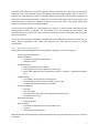
2.3 Processes to be used
2.3.1 Description of the development process
Although we will not choose for one specific development process, we will borrow mainly from agile
approaches (see the glossary for an explanation). This will particularly mean to develop in small
iterations, each embodying only small changes compared to the previous iteration. Furthermore we
will incorporate the project customers regularly by asking for feedback to ensure that the product is
still accepted.
Asking for feedback will be one of the main verification techniques we will apply in the requirement
analysis phase. After all this document defines what the client will get. During the design phase(s) we
will sculpture an adequate software architecture and design by starting on a high level of abstraction
and drilling more into detail iteratively.
For the implementation tasks we will ensure high quality code by several means. First we will adopt a
test-driven development, i.e. a development style where first a unit test is written and after that the
actual code which passes this test is implemented. Then the code is refactored to improve readability
6
and code reuse. Finally the cycle starts again by writing a new unit tests. This way the code grows
organically and code coverage during unit testing is extremely high. Besides TDD we will try to
exercise pair programming as much as possible, where one person is continuously reviewing the
code that is currently being written. A third way to improve code quality will be code reviews. For
important pieces of code the programmer presents the source code to the group which gives
feedback on quality, style and comprehensibility.
On the level of integration and system testing we will try to perform tests automatically and
systematically as much as possible. For tests where this is not possible we will provide clear
documentation of test cases and results to ensure validity of the tests. These means will all assure a
high level of quality.
As we use short iterations, adapting to changes will be less difficult and have less impact than in
other "heavy" approaches. This makes this approach less risky and less prone to missing
specifications.
2.3.2 Documents and products
We will deliver the following documents and products during the course of the project:
-
-
-
-
-
Project plan (this document)
Analysis document
o Functional and quality requirements
o Global use cases
Design document
o Overall architecture of the system
o Class diagrams of classes important to the design
o Other UML-diagrams where appropriate (activity-, sequence-, deployment-diagram
etc.)
Implementation
o A compiled, running version of the program
o Documented java source code including unit test code
o An extracted API-documentation ("javadoc")
Test documentation
o Test plan
o Unit test report
o Test description and reports for integration and system tests
o Acceptance tests report
Other documentation
o Program manual
Other products
o A CD with all digital documents and products on it
o A poster
o A presentation of the project
Most documents will be delivered in multiple iterations and may grow and change over the course of
the project.
7
2.3.3 Extra notes on project organisation
All documents are versioned and stored in a version control system to allow access on earlier
versions easily. We will keep track of bugs with designated bug-tracking software to make bug fixing
more traceable.
2.4 Subsystems and planned releases
The system shall consist of three subsystems:
-
Parser: reads the OWL input and converts it to an internal data structure.
Director: divides the plot into scenes and writes a film script for the scenes.
Presenter: generates an animation from the film script.
The parser system is provided by the HMI group, so the goal of our project is implementing the
Director and Presenter subsystem. The Presenter is designed as a replaceable part, making it possible
to exchange the default Flash Presenter with another presentation medium.
As described in 2.3 we will implement the subsystems in an agile fashion with small iterations. This
means we will build the system rather horizontally (all modules at the same time, starting with a lot
of stubs and adding more and more real functionality over time) than vertically (completing one
subsystem after each other). As a consequence we do not schedule releases of single subsystems.
Rather we will release iterations of the whole system.
The final release of the project is at Friday the 29th of June 2007. We are planning to release a
prototype of the system two weeks before the final release.
2.5 Risks and challenges
The greatest challenge of this project is the very large number of unknown requirements. At the start
of the project, the only thing we knew were the basic requirements of creating a recognizable
animation from a plot. First of all, the term 'recognizable' is hard to measure and will vary from
person to person. Besides that, the way in which the plot should be transformed into the animation
is completely unknown.
Furthermore, the exact approach for creating the animation has rarely been used before. Therefore,
the project consists of a lot of research and prototyping. Using the wrong approach - how plausible
the solution may seem - is a high risk. The used processes try to reduce the chance of failure by
supporting short iterations and much communication in the team.
Failure of the prototype due to the wrong decisions may not cause complete failure of the project.
The project is more a research process then only the implementation of a prototype. In case the
prototype won't work, we probably can draw a reasonable conclusion and make some suggestions
for further work.
2.6 Tasks
We have chosen to assign new tasks to project members every few weeks. This way we will ensure
that everyone has about the same level of experience with all components of the project. This
prevents code ownership and the creation of 'experts' on a particular subject, while the rest of the
group knows nothing about it.
8
2.7 Team
Our goal is to work in two separate teams on this project. The two subsystems (Director and
Presenter) are only through the film script data structure connected to each-other. Therefore,
working on both systems at the time should not be a problem. To overcome the problem of code
ownership and the creation of experts for only a small part of the system, we decided to circulate
persons between the groups. The Director group consists of three people, the Presenter group of
two. After two weeks, two persons switch their positions to become an expert on a new field.
Besides that, they can review and improve the code of others.
The skills needed for the completion of the project are the following:
-
Basic knowledge of the structure of OWL and TRIG files
Knowledge of the SPARQL query language for OWL and TRIG files
Java
Flash and Action Script 3.0
The Action Script 3.0 requirement is introduced after migrating from 2.0 to 3.0. Some features of the
Flash Presenter needed features of Action Script only present in version 3.0.
2.8 Schedule and milestones
During the course of the project the schedule has changed many times. We first created a schedule
with very little detail, defining only the global tasks that had to be done (like 'presenter', 'director',
etc). We also defined a number of deadlines at which a specific percentage of the project would be
finished.
After a few weeks it became clear that this type of schedule did work well as we were falling behind.
It was hard to measure progress and to concentrate on the things that needed to be done. Because
of this, we decided to assign everyone specific tasks at each meeting and to add these to the
schedule.
During the next weeks the project moved at a faster pace, but a different problem came up. It is
difficult to schedule 'work sessions' with people that all have different personal appointments and
schedules. Our solution was to plan a few weeks ahead, scheduling the work sessions during our
meetings.
Something else that makes scheduling difficult is the 'discovering' nature of the project. Almost every
week we encountered new problems or ideas that required us to adjust the schedule.
An example of a schedule we used is included below:
Week
Task
Who
When
19
Get properties and entities to work
properly; start design analyser
Prototype AS3; Convert presenter to
AS3
Finish half of film script actions;
create plain-text presenter
Low-level design space/time analyser
Edwin, Isaac, Ronald
Andre, Ivo
wed morn (Is+Ro), thu
morn
fri aftern, mon
Isaac, Andre
thu, mon
Ivo, Edwin, Ronald
wed morn, thu (Iv+Ro)
20
Table 1: Example of a planning schedule.
9
10
3 Domain Analysis
3.1 Introduction
The project is settled in the domain of Virtual Storytelling (VS). This domain deals with the
generation, interpretation and replay of artificial stories. The stories are artificial in the sense of "not
being thought up by humans". In this chapter we will provide a domain analysis on Virtual
Storytelling to provide background information which is required for understanding the problem this
project is meant to solve.
3.2 Users
As Virtual Storytelling has not grown fully mature by now, the product is not intended as a final
product for end users. More likely it will be used by members of research teams in the field of VS.
These research teams explore the possibilities and caveats of VS. Because there is a lack of software
that visualizes the results of generated fabulas the software will support those teams in evaluating
the results of their research.
Often, users refuse to apply new techniques and products in their daily work. However, VS is strongly
connected to computers; so people in this field are used to using software programs. Therefore, we
expect the users to be open for a new piece of software that can support their research.
3.3 The environment
VS normally takes place in common computer environments, that is, no special equipment is used.
The software used for VS runs on common hardware. Often it is even written in platformindependent programming languages such as Java.
3.4 Tasks and procedures currently performed
The HMI department of university of Twente has several software products regarding VST. These
products together form the Virtual Storyteller. (Virtual Story Teller)
Research is done on multi-agent environments that are able to produce fabulas using artificial
intelligence. Besides the automated generation of stories, the HMI department has developed a
graphical editor to create a fabula by hand.
Next to these generation software the HMI department has development different tools to "replay"
the generated fabula. The so-called NarratorAgent is able to output the generated fabula in natural
language. The output of this agent can be used by a dedicated speech generator that translates the
natural language to spoken words.
3.5 Competing software
INESC-ID (INESC-ID) has established a similar virtual storytelling project. Its site has not been
updated for a while and we have the impression the project is not yet as advanced as the HMI VS.
Proof-of-concept software for animation of simple plots has been developed by OFAI (OFAI, 2006).
The project also includes agent-based ‘story’ generation for a very limited world.
11
3.6 Similarities across domains and organizations
Although the product is specifically made for the field of Virtual Storytelling its functionality is
independent of the source of the fabulas. As long as the input is given in the form of a fabula, the
product should be reusable in a wide domain of applications. This includes:
-
Visualisation of process workflow in almost any domain
Visualisation of fairy tales for children
Application in low-bandwidth scenarios where the fabula is retrieved from a server and
visualised on the client PC
12
4 Requirements Specification Document
4.1 Purpose of this chapter
The purpose of this chapter is to specify the requirements that the final product has to fulfil. Only
when the product satisfies the requirements it is considered finished. As any change that is made to
this document might have a major impact on any later stage of the project, acceptance is required
from as well the development team as the client.
4.2 Problem
The HMI department have developed a system called Virtual Storyteller that is capable of
automatically generating virtual stories, so-called fabulas, and translating them into natural language
and speech. However, a suitable subsystem able to visually display the generated fabula does not
exist yet. The purpose of this project is to develop a software program that is able to visualise and
animate a fabula that has been generated by the Virtual Storyteller.
4.3 Functional requirements
Requirements described in this section describe the features that the system provides to the user. It
is important to keep in mind that it is not the "how" that is described here, but rather the "what".
Therefore we will not go into implementation details.
4.3.1 Primary functionality (must)
This sections covers functionality that is absolutely vital to the working of the product.
1.
2.
3.
The system must allow the user to open a trig file that contains the fabula, the plots and a
reference to the fabula ontology (stored in owl files)
1.1. The system must provide a facility to the user to select a single trig file to open.
The system must translate the information stored in the fabula into a film script.
2.1. The system must be able to handle a specific minimal set of actions, goals, events and
other ontology elements to be able to at least visualize one specific example fabula.
2.2. The system must make decisions about what parts of the fabula to drop if these parts are
not important for the understanding.
2.2.1. Dropping parts of the plot must not change its meaning.
2.3. The system must fill missing information in the plot with reasonable information.
2.3.1. Adding information to the plot must not change its meaning.
2.4. The system has to split the plot(s) in the fabula into logical scenes.
2.5. The film script has to contain a time line that places each event in the script at a specific
place in time.
2.6. The film script has to contain direction commands that define the setting of each scene
(backgrounds etc.), camera actions (like position, angle, pan, zoom, fade-in, fade-out),
position and state of all elements (actors, objects)
2.7. The film script has to contain action commands that define everything that happens in the
scene, like movements, changes in the state of an object/actor (change in feeling,
movement etc.)
2.8. The system must be able to handle actions that take place at different locations at the
same time in a reasonable way without dropping important information.
The system must send the content of the film script to an attached presenter.
3.1. The system must support the ability to use alternative presenters.
13
4.
3.2. The system must provide a means for the user to select the presenter that will be used to
visualize the film script.
The graphical presenter must (at least) indirectly visualize the content of the film script.
4.1. The graphical presenter must present the commands in the film script graphically to the
user.
4.2. The graphical presenter must use graphics to visualize the visible entities in the film script
(actors, objects, backgrounds), e.g. bitmaps or 3D-Meshes.
4.3. The graphical presenter must choose graphics in a way that visual elements that have to be
distinguished to understand the plot are presented differently. For entities that are
allowed to be indistinguishable equal graphics may be used.
4.4. The graphical presenter must at least be able to visualize all actions, events, feelings etc.
that the film script contains for the example fabula mentioned in requirement 2.1
4.3.2 Secondary functionality (should)
Functionality in this section is not as crucial to the project's success as the primary requirements.
However they are still considered important.
1. Extended visualisation
1.1. The graphical presenter should generate animations in the visualization, i.e. elements in the
scene must actually move if the film script says so. Displaying static images (like a comic
strip) is not enough.
2. The graphical presenter should display visual film script commands as text on the screen for
which it does not have a visual representation.
3. The graphical presenter should read the relation between entities and their visual representation
(bitmaps etc.) from a database that can be edited without the need of recompiling the presenter.
The database can be as simple as e.g. an xml file or similar.
4. The system should provide a short description about the file that has been loaded.
4.3.3 Optional functionality (could)
This section contains functionality that extends the core functionality of the system. Although they
are "nice to have" they are not important for the success of the project.
1. The presenter could be able to not only present a film script visually but support audio output as
well (background music, sound effects, speech)
2. The presenter could visualize the scenes in 3D instead of 2D
3. There could be an editor for the database (secondary functional requirement 3) that allows the
user to edit the visual details for a specific entity (e.g. princess) under specific conditions
(running, standing, being scared etc.)
4. The editor could be able to read ontology files (owl) and present their content to the user. The
user would then be able to define simple rules, like "for entities of type princess with a feeling of
scared use bitmap scared_princess.jpg"
4.3.4 Functionality outside of the project scope (won't)
This section exists to define functionality that we will not implement in the course of this project.
This allows us to specify the boundaries of the project more clearly.
1. The project will not contain a dedicated trig/owl parser. We will use an existing one.
14
2. The project will not create trig or owl files. These input files have to exist before execution of the
program.
4.4 Non functional requirements
4.4.1 Quality requirements
1. Use of resources
1.1. During execution of the program the system is allowed to use 100 percent CPU power to
process as fast as possible.
1.2. During visualization of a film script the presenter is allowed to make full use of the system
processing capabilities (CPU, GPU, other hardware). To assure flawless visualization it might
be required to shutdown other applications that make use of resources.
2. Reactivity
2.1. During execution of the program the system must react on user input within a reasonable
amount (i.e., within several seconds), e.g. by cancelling the current operation.
3. Reliability
3.1. The system must be able to handle bad inputs in a reasonable way by providing feedback to
the user and without crashing.
3.2. The system depends on hardware and other software (OS, drivers, OWL-parser). Errors in
these external components may always lead to unexpected behaviour of the system.
4. Extensibility/adaptability
4.1. The system must be designed and implemented in a way that presenters may be added
without the need of changing the code base of the director.
4.2. Changes in the ontology might require changes in the director code. However, the system
must be designed and implemented in such a way that these changes require minimal
changes in the existing code base. Preferably only extension of the code is required.
4.3. The system will be localized in English. Localizations in other languages are optional.
5. Reusability
5.1. The system components should be designed in such a way that they are reusable. Therefore
we encourage loose coupling of all components.
6. Usability
6.1. The product should be simple to use. After an initial setup (providing the required
parameters), the user should not have to intervene in the course of execution.
6.2. For an indirect presenter the user might have to perform additional steps to see the results.
These steps should be simple and well documented.
4.4.2 Platform requirements
1. The system will be written in Java, version 1.5 (J2SE 1.5)
2. The system running the application must fulfil the following requirements
2.1. Java 2 Second Edition Runtime Environment 1.5 update 10 or compatible
2.2. A decent processor capacity (e.g. not older than three years) being able to run the presenter
(depends on the presenter that we will choose)
2.3. At least 512 MB RAM, preferably 1024 MB RAM or more
3. Depending on the presenter implementation additional software (libraries, O/S) might be
required.
4. Depending on the presenter implementation additional hardware (graphics accelerators) might
be required.
15
4.4.3 Deliverables
For a list of deliverable product see the project plan.
4.4.4 Software requirements
1. Programming language
1.1. The core product will be written in Java, using the syntax as of version 1.5
1.2. Additional parts of the product, especially the presenters, may use specific languages. As
an example, a Flash presenter is most likely to use ActionScript as its programming
language.
2. Programming standards
2.1. The Java code has to be written according to Code Conventions for the Java Programming
Language. (Sun Microsystems, 1999)
2.2. The team is going to practice Test Driven Development (TDD, 2007).
2.3. To overcome the limitations of TDD, the team will use additional techniques to improve
code quality, such as pair programming.
3. Documentation
3.1. The public API of the software has to be documented using the JavaDoc syntax (Sun
Microsystems, 2004).
3.2. The source code has to be as self documenting as possible. Where necessary or useful, the
source code has to be augmented with meaningful comments.
4. Interfaces
4.1. There are no specific restrictions to the user interface that the product will have.
4.4.5 Process requirements
1. Responsibility
1.1. The software will be delivered as-is. The development team cannot be made responsible for
financial damage, loss of information or damage to persons that are caused by the usage of
the software.
1.2. The development team tries to finish the project within the given time frame. The team is
not obligated to work on the project after a grade has been given to project. Of course,
team members might choose to work on the project voluntarily after a grade has been
given.
2. Copyright and usage rights
2.1. As for all products made for the Twente University, the usage rights are exclusively
transferred to Twente University.
4.5 Discussion on requirements
In general it is the purpose of the requirement specification document to point out the requirements
in a concrete, specific and measurable way. This project, however, is for a certain extent a research
project. Therefore it was not possible for us to specify all requirements as much in detail as it would
have been done in more "conventional" projects. Especially it is difficult to assign quantitative values
to many quality requirements. In these cases we can only specify our expectations. This part of the
chapter sums up the discussion on those requirements.
4.5.1 Regarding functional requirements
Primary Functional Requirement (PFR) 1.1 mentions the ability to provide a trig-file to the system.
This can happen in the form of a command line argument as well as graphical user interface GUI. The
16
selection of a trig file also implies the set of owl files that are used. The system must be able to find
these files.
PFR 2 states that the program must translate the fabula to a film script. We consider the film script as
a means of abstraction a crucial requirement rather than an architectural choice. It is the prerequisite
for PFR 3.1 (alternative presenters).
The minimal set of supported entities and properties mentioned in PFR 2.1 is not specified. We will
provide at least one example fabula. The ontology elements used in this fabula are described in the
test plan.
PFR 2.2 and 2.3 are obviously vague. They are rather an expectation than a requirement. However,
we consider these points to be very important, so we list them as functional requirements.
In PFR 2.6, several additional events and actions are mentioned, like camera actions. The important
point here is that the system must support them. It is not actually crucial to have all of the
commands built in.
4.5.2 Regarding use of resources and performance.
We do not expect the system to store much information on the hard-disk during normal execution.
Temporary output of any parts of the system will not exceed 10 MB (except log-files). Depending on
the application settings and the input, the log-files might grow to several MB of data. However,
logging will be configurable to be minimal or even off. Hard disc space should not be an issue for the
program, given that today's computers in general have large hard discs.
The expected use of memory (RAM) is similarly reasonable. Common sizes of built-in RAM range
between 512 MB and several GB of RAM, which should be enough to run the Java application or
reasonable large input fabulas.
The translation of a fabula to a movie is not expected to take longer than one minute.
Of course we will try to deal economically with resources, using appropriate data structures.
However, when given a choice, we will prefer usability and clearness over economic use of resources
(memory usage as well as speed). We consider this project a prototype rather than a final product, so
comprehensibility and maintainability are of prior concern.
4.5.3 Regarding extensibility/adaptability
Extensibility is one of our primary concerns. The input (fabula and its ontology) can vary dramatically
and so can the computations to handle them. This means that the system has to be extended to
support new ontologies. The importance of this quality requirement will have a large impact on the
architecture and design of the software.
17
5 Problem Analysis
In this chapter we will derive a high-level analysis of the problem using a top-down approach. This
will lay the basis for the architectural and design decisions. Note: when we speak of fabula in this
chapter, we normally mean the fabula (trig file) and the ontology it uses (owl files).
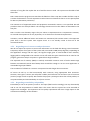
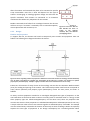
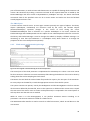
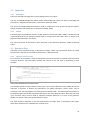
To put it simple, the primary problem the
Fabula
Visualisation
product has to solve is the visualisation of a
fabula, or put in another way: the
transformation of a fabula into a visual
representation (PFR 2). We can see this
transformation as some sort of pipeline that
transforms the input data (fabula) to its output Figure 1: The problem to be solved – from fabula to
format (visualisation). This chapter will define the visualisation.
basic steps in the transformation pipeline and
define the basic building blocks the pipeline will be made of.
One of the main concerns regarding the product is the required extensibility (see non functional
requirement 5, Reusability). The most obvious point of extension is the ability to use different
presenters, that is, different visualisation end-points. During the transformation from fabula to
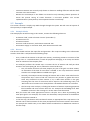
visualisation there will certainly be
logic that is shared by all presenters.
It is therefore a natural choice to
define at least one intermediate
product. This intermediate product
is actually already defined in the
Fabula
Script
Movie
requirements: the film script. We
Figure 2: Basic components and their products. The fabula serves as input can therefore split the process in at
for the director which creates an intermediate film script. The script is
least to large subsystems: The
used by the presenter to visualize the movie.
director and the presenter(s). The
director implements the common tasks that ultimately lead to the film script. To do so it receives the
fabula as input. The presenters need to interpret the film script in a way specific to their way of
visualisation. The splitting into two subsystems has large impact on the architecture of the system.
The two subsystems can be described like this:
Director
Presenter
Input:
- A fabula (trig + owl files)
Input:
- The film script made by the director
Tasks:
- Analyse the content of the fabula and
generate a film script
Tasks:
- Convert the film script into the
"native" format of the presenter, for
example a Flash movie in the case of a
Flash presenter.
Output:
- The film script
Output:
- Visualisation of the fabula
18
Of course this is a description way to coarse, so we need to flesh it out more.
5.1 The movie metaphor
Before we analyse the two subsystems in detail, we would like to call attention to our use of terms
from the world of movies. Given that the final goal of the product is the visualisation of a fabula as a
film, this metaphor seemed quite natural to us. The analogies between the project and the creation
of a movie are not always perfectly given, though. Note that for example that there is the possible
misconception with the film script as the result of the director's work. In the real world, the script
(screenplay) is rather input for a director than the output of his work. Still we will use terms like
director, cutter and film script, as their meaning in the system is at least comparable to the real
world.
5.2 Tasks of the director
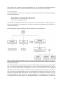
The director actually does most of the work with respect to understanding the fabula and its
ontology. As stated in the terminology of the requirement specification document, the fabula
consists of entity class instances and properties found in the ontology. These instances and
properties describe all events, states and goals that define the plots. However, the fabula data is not
given as a linear list of events
and changes in the world, but as
a network in which all entities
are nodes that can be connected
to define the meaning of the
plots.
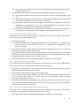
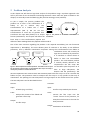
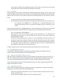
Figure 3 shows an
example of such a network.
The difficulty of this network lies
in the fact that it represents
pure knowledge rather than a
list of events. The film script, on
the other hand, should exactly
be such a linear list of events.
Figure 3: Part of the network that defines a fabula. In this case, a part of the The presenter will most likely
well known story of Little Red Riding Hood is shown.
show the plot(s) in the fabula
linearly, so that the main task of
the director is to create a linear representation of the knowledge found in the fabula. This task can
be split into two subtasks: the analysis of the knowledge and the linearization of it.
During the analysis task the meaning of the entities regarding the plot has to be found. It is highly
likely that not all knowledge in the fabula has to be used for the film script. Therefore, the analyser
task should ignore that knowledge (FPR 2.2). On the other hand, pure knowledge might not be
enough to derive a film script. This requires the analyser task to add implicit knowledge – or even
pure assumptions – to the knowledge (FPR 2.3). In no case should these modifications change the
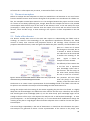
meaning of the plot to a high degree. We will call the subsystem that is used for this task the SpaceTime Analyser.
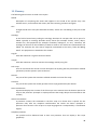
The second large responsibility is the task of linearization. It should use the information the spacetime-analyser has gathered to derive a linear representation of the actions in the plot(s). One
19
difficulty of this task is the fact that actions at different places
might overlap in time (PFR 2.8). The general solution to this is to
split the events in the fabula into logical groups (scenes) and
hand each scene one after another over to the film script. We
expect this to be quite challenging – which events actually
belong together to form such a logical group? Again, we use an
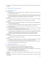
Figure 4: Two subsystems of the director – analogy from the world of movie and call the subsystem that is
The space time analyser and the cutter.
responsible for the linearization of the fabula the Cutter.
Both the SpaceTimeAnalyser and the Cutter will contain a fair amount of complex algorithms.
Because extensibility/adaptability is a major concern, we will keep this in mind and will try to make
these components exchangeable. How this works will be specified in more detail during the design
phase.
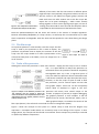
5.3 The film script
An important question is: what actually is the film script? The film
script is used by the presenter to tell it what to display. The
presenter only decides how to display the contents of the film
script. The film script should be a linear representation of the
Figure 5: Film scripts are made of
action that takes place in the fabula, so we can simply see it as a actions.
list of "actions".
5.4 Tasks of the presenter
Although the task of the presenter is much more obvious – display the film script in one or another
way – it is quite difficult to analyse the presenter. As
mentioned earlier the presenter should be completely
exchangeable (PFR 3.1). From a high-level point of
view, this makes the presenter almost a black-box with
a well known interface and input data (the film script).
However, in this film script we plan to build at least
two presenters, one for textual output and one that
uses graphic output. These two can be conceptually
broken down as displayed in Figure 6. The textpresenter will merely write textual output to the
console. Its purpose is primarily to support debugging.
The graphics presenter is more complex. It will use
different kind of visuals, like bitmaps, videos, text or
other graphical shapes, to visualise the content of the
film script (PFR 4.1). This will ask for some kind of resource management (SFR 3).
Figure 6: Concept of two different presenters. The
Text presenter uses the console to output the
events of the fabula. The GraphicsPresenter is more
sophisticated and uses graphic primitives such as
bitmaps, shapes or text.
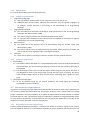
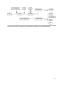
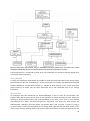
Figure 7 shows the concepts of the system as a whole. Keep in mind that this diagram only
represents a conceptual model which not necessarily maps to the design of the system. In later
design phases, the concepts will be refined in more detail. Some concepts may actually be removed
or replaced by different components.
20
Figure 7: Conceptual diagram of the system. The diagram shows the different steps in the processing pipeline: the fabula
is analysed, cut into scenes, transformed into actions and then presented by one of the available presenters.
21
6 Design Document
This chapter describes the global design of the system. The first section will explain the global
architecture and give an overview over the two main subsystems of the application. The second and
third section will cover these subsystems in greater detail.
6.1 Global architecture
As mentioned earlier an important concern of the project was the extensibility of the product. New
ontologies are likely to be developed which will ask for more or less modification in the product. Our
architecture should reflect this by clearly defining the varying and the constant parts of the system.
Actually the core, that is, the constant part of the system can be quite small. It has the following
major tasks:
-
Setting up and connecting the variable parts of the system
Housekeeping of intermediate data structures such as the fabula and the film script
Delegating work to the appropriate variable subsystem during the given processing steps
Around this core there are a lot of extension points that represent all the variable parts in the
system. These extension points are:
-
The SpaceTimeAnalyser
The Cutter
The Emitters (see below for an explanation)
The Presenter
The Actions
The Emitters need some explanations. In the conceptual diagram made in the previous chapter there
is a missing link between the director and the film script, which might not be obvious first. While the
space-time analyser and the cutter are able to create logical scenes from the fabula, the translation
to actions is not trivial. Consider for example an entity Attack with its two properties agens and
patiens, which define the attacking character and the one being attacked respectively. This single
entity might require several
actions to appear in the film script:
at least the attacker has to move
to its opponent and has then to
attack him. The first action is not
necessarily given explicitly in the
fabula, so there is not a one-to-one
relation between entities and
actions. This gap is filled by a
concept we call Emitters. An
emitter is an object responsible for
Figure 8: Core service and extension points. The core services
emitting (hence the name) the
actions that are required for a given situation (entity, context etc.). As the emitter strongly depends
on the ontology, we will make it an extension point as well. Figure 8 shows this architecture as a
high-level class diagram. The extension points are given as interfaces.
22
6.2 Director
This chapter describes the design of the director module. As stated in the chapters on problem
analysis and architecture, this module is responsible for the translation of the fabula to the film
script, as stated in PFR 2.
We will first give an in-depth view on the working of the director, followed by more formal design
using class- and other UML diagrams.
6.2.1 General working of the director
Recall from the problem analysis the input and output of the director:
Input
The input for the director consists of the fabula and the corresponding ontology. The fabula is
contained in a trig-file; the ontology comes in the form of one or more owl-files.
Output
The output of the director is a list of commands that define the film script. This film script can then
be used by the presenter.
Parsing and interpreting fabula
The director uses third party software to parse the fabula and the ontology file. The SPARQL query
language is then used to get the required information out of the parsed date.
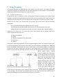
The first goal of the director is to locate all entities of the fabula in a space-time coordinate system.
Doing so will allow the director to divide the knowledge into scenes, as required by PFR 2.4. In the
space-time-coordinate system the x-axis describes the relative time of events (actions, world
changes) in the fabula. The y-axis contains discrete locations where the actions take place ("forest",
"castle"). To build the coordinate system the director first collects all entities in the fabula. It then
tries to find out which entities describe the location/site of other entities. This information is used to
build a collection of sites at which the scenes will later play.
All entities are then placed in the space-time system. The location on the space-axis is determined by
scanning for information that describes the location of the entity. For physical objects this can be
quite explicitly given, as often physical objects have a location mentioned (for example with the
locatedAt-property), or they are somehow connected to physical entities for which the location is
known. In these cases, there is no need to augment the given knowledge with assumptions.
For other entities such as emotions their location is given implicitly by the objects to which they are
connected. Quickly it became clear that the definition of an entities location can be quite
sophisticated. It is nearly impossible to find a generic algorithm to define the location of arbitrary
entity. This is primarily caused by the fact that the ontology can change drastically. According to the
architecture, the director should be as ontology-agnostic as possible, i.e. it should not depend on too
many classes and properties in the ontology. A hardcoded solution is therefore not feasible. Our
system deals with this problem by using a flexible, plugin-like structure, which will later be described
in more detail.
The location on the time-axis is primarily determined by the value of attached FabulaKnowledge:time
entities. Time is only considered relatively to agree on an order of events. It is the task of the
23
presenter to interpret the duration of events, i.e. to map relative timing to "physical" time units such
as seconds.
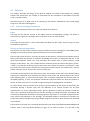
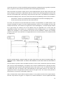
For entities that have no explicit time
attached determining the place in time is
more difficult. For example: if the story
tells about a character picking up an
apple from the ground, the apple –
although not mentioned earlier – has to
"exist" before it is ever mentioned. The
director must propose a reasonable
"start" time for that existence, for
example at the beginning of the scene.
In the example in Figure 9 the letters A –
G represent entities found by the director
in the fabula. The type of the entities is
not important at this moment. Entity C is
Figure 9: Events in the space time grid. In the diagram the x-axis present at multiple locations. It could be
describes the relative order of the entities A-G. Each occurrence of a character moving from one scene to
an entity denotes some event. The y-axis contains the location at
another.
which the events take place.
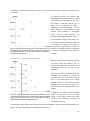
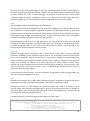
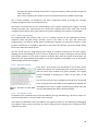
Generating a script from the space-time
After the space-time coordinate system
has been build the director has to
convert this information to a linear set of
commandos that will be sent to the
presenter
This can be done by scanning along the
time-axis and collecting all entities on
the space-axis for the current point in
time. If the fabula does not contain
parallel actions, i.e. two or more actions
happening in more than one place, this
will lead to a linear representation of all
events.
If, however, the fabula contains parallel
Figure 10: The space-time grid is parsed along the time-axis. The red actions the director has to do more
line describes the current point in time which the director currently
work. It will detect scenes that take
parses. Events that cross the red line at the same time but at
place at the different locations, as
different locations indicate overlapping scenes.
required by PFR 2.8.
Two parallel scenes, the director should linearise this as ABCCDE. How the scenes are detected is not
clear in detail and will be left as an implementation detail.
24
After the entities are linearised they have to be converted to specific
script commandos. How this is done will depend on the type of
entities. Encouraging an ontology-agnostic design we will leave the
specific translation from entities to commands to an extension
mechanism that allows easy adaptation of new entities.
Besides commands that follow from ontological entities the director
will have to inject "cinematic" commands, such as scene descriptions,
Figure 11: Two scenes. ABC and
camera placement and movement, etc.
6.2.2
Design
CDE describe two series of
events at two different
locations; thus, two different
(overlapping) scenes.
Entities and properties
To support PFR 2.4, the director will need to temporarily store entities and properties from the
fabula. The following class diagram describes the classes:
Figure 12: Classes regarding entities and properties. OntResource is the basic interface for ontology elements defined by
Jena. An entity in the fabula has a specific type, the OntClass. In the same way, a property is an instance of a specific
property kind, the OntProperty. A Graph is a group of entities that can be referenced as if it was an entity.
Entities are all instances of entity classes in the ontology. We use the Jena Semantic Web Framwork
(Jena) for loading and parsing of the entities. This framework provides interface that correspond to
entity classes (OntClass) and property types (OntProperty). Given the Jena parser, the PFR 1 is
fulfilled.
An entity can have properties attached to it. Ontologies distinguish two types of properties: on the
one hand there are those that attach a value to an entity (such as a Boolean value or a string). In RDF
these property types are called DatatypeProperty. On the other hand, there are properties that
connect two entities. These properties are called RelationProperties. RelationProperties do not carry
a simple value but rather connect two entities together. A RelationProperty "locatedAt" for example
uses the related entity to describe the location of the entity to which it belongs. We do not explicitly
separate the two types of properties in our design. OntProperty has a method getValue which
25
returns either the primitive value (DatatypeProperty) or the connected entity (RelationProperty).
Separating the two types of properties would have increased the complexity of the system.
Processing classes
As described above we have three primary points of abstraction caused by the fact that ontologies
are considered dynamic.
-
Decision where an entity belongs on the space axis.
Decision where an entity belongs on the time axis.
Emit script commands per entity.
The decisions on the placement of entities in space-time have to be made on a rather high level, i.e.
with more overview of all existing entities. The script commands are expected to be very specific for
a certain type of entity.
The following class diagram describes the classes that deal with these decisions:
Figure 13: Ontology dependent objects. The director uses several exchangeable sub modules to do its task. The
SpaceTimeAnalyser locates entities in place and time. The cutter then creates scenes. Finally, the emitters translate from
scenes to film script actions.
The SpaceTimeAnalyser is an abstraction of the strategy used to place entities on the space-time
grid. It is partially responsible for matching PFR 2.2 and 2.3. In the SpaceTimeAnalyser for the first
time the system decides which knowledge to drop and what information to add. Dropping
information occurs if the analyser is not able to locate an object in place and time or if it finds an
entity irrelevant for understanding the story. Goed candidates for dropping are entities that describe
motivations and goals. While these entities are very important for the actors in the fabula, they are
hardly displayable in general. Information is implicitly added if it is reasonable to make assumptions
on the place and time of an object. The SpaceTimeAnalyser is only replaceable as a whole. This
26
caused the decision to make the (default) SpaceTimeAnalyser implementation as greedy as possible,
that is, to gather as many entities as possible rather than dropping information.
After the entities are placed in space-time a Cutter implementation extracts single scenes from the
space-time grid. This feature is requested in PFR 2.4. It does this by selecting a group of actions from
the sites as described under "Generating a script from the space-time". One difficulty is the ability to
deal with overlapping scenes. There are several rules that can help defining scenes in such situations:
-
Pick at least n actions at a location before switching back to the other overlapping scene
If two scenes overlap, start with the scene that ends first
Per scene, the emission of script commands from entities is encapsulated in so-called Emitters. Two
concrete examples are given, one that handles Movement actions in the ontology and one that
handles Take-actions. The emitters are registered in the EmitterRegistry. To find the proper Emitter
for a given Entity the emitters can be ask whether they are applicable. This is done with the
isApplicable method. The emitters are a manifestation of the strategy pattern. As a consequence
adding new "strategies" is easy. Therefore the director can be extended to support new ontology
entities in the future. The minimal set of supported events as stated by PFR 2.1 can therefore easily
be augmented.
Figure 14: Sequence diagram - finding an emitter for a given entity and let it emit actions. The emitter registry uses
isApplicable to find a suitable emitter. The director calls emitActions on that emitter which will create actions as
necessary.
How this works in practice: After the fabula has been cut into scenes, the director passes all entities
(per scene) to the EmitterRegistry. The Registry tries to find a suitable Emitter by passing the Entity
to isApplicable of the emitters and checking the result. If the result is "true", the emitter knows how
to handle the entity. The director then calls emitAction on the Emitter which in turn returns the
appropriate actions. This generates the film script for the given scene. The script is then passed to
the presenter. This process is described in Figure 14.
PFR 2.5 requires the script to define a specific timeline. In our product we chose for a simple solution:
the film script actions are given as a simple list of Action-realizations. A more sophisticated data
27
structure might be usable for the film script, however we chose to use the list, as it is less code for us
to maintain. However, it should not be too much work to switch over if later it appears to be
reasonable to use a dedicated class for the film script.
The action interface is implemented for the specific actions. Each action implementation holds the
information that is necessary for the presenter to visualise the action.
6.3 Presenter
The presenter is in charge of using the film script to depict the story on some sort of medium. The
presenter is an interchangeable part of the system, making it possible to use different presentation
techniques (PFR 3.1). We made a text presenter and a graphical presenter using flash.
6.3.1 Text presenter
The Text presenter is a very basic presenter primarily used for debugging purposes. We could
improve this version, but we chose to focus on the visual flash presenter since that was the real
challenge of our assignment.
6.3.2 Choice of graphic presentation technique
The final goal of the project is to display a fabula visually on the computer screen. Available
techniques for displaying graphics are virtually countless, so we needed to decide for one of those
techniques. Are main requirements were:
-
-
Ease of use: the learning curve must not be too steep; programming the presenter must not
be too difficult. Because the main purpose of the project is de transformation between plot
and animation and not the animation itself, we are looking for a simple way to animate
simple actions.
High expressiveness: we wanted the presenter to be versatile regarding displayable formats
and film script actions
Support for animations: the presenter needs to able to animate the content on the screen in
one way or another.
During our project we considered four different presentation techniques, namely Flash, JOGL, Panda
3D and SVG.
Flash
The combination of Flash CS 3 (Adobe, 2007) and ActionScript 3.0 give many possibilities to create on
the fly animations. Some advantages of Flash:
-
-
ActionScript is able to read XML and transform it into a manageable object structure.
It is possible to load external images of movie clips. Loaded movies can be controlled by
Action Script, for example for showing a different frame of playing an animation. This makes
it possible to create actors with several mood expressions (e.g. happy and sad) and basic
animations like walking.
With the properties of loaded elements, it is possible to move movies across the screen and
maintain a depth ordering of items.
Flash supports scenes, which might be useful to represent a storyboard representation
There is a notice of (relative) time in the form of a setInterval and a getTimer method.
28
Of course, there are some disadvantages as well. The main disadvantage of Flash and ActionScript is
the lack of a higher level animation function. Whereas you can define simple animations like moving
an object around the screen in other languages, ActionScript is more low level. Creating such
animations should be done by changing the value of a (x,y) property on a fixed interval. Due to the
complete language, it won’t be very hard to creating higher level functions for this problem.
JOGL
JOGL (CollabNet, 2007) is a Java Binding for the OpenGL API:
The JOGL project hosts the development version of the Java™ Binding for the OpenGL® API (JSR-231),
and is designed to provide hardware-supported 3D graphics to applications written in Java. JOGL
provides full access to the APIs in the OpenGL 2.0 specification as well as nearly all vendor extensions,
and integrates with the AWT and Swing widget sets. It is part of a suite of open-source technologies
initiated by the Game Technology Group at Sun Microsystems.
Although OpenGL states to be for 2D and 3D practices, the most demos from JOGL are in 3D. After
studying the JavaDOC from JOGL, I couldn't find any classes and methods for handling external files
or images and display them on the screen. Given the purpose of OpenGL, I think the JOGL is too
powerful for the simple animations we want to make.
Panda3D
Panda3D (Carnegie Mellon University, 2002) is based upon simple Python scripts to generate
animations. Panda3D is mainly focused on 3D animations. The environment and actors are external
files in the so proprietary "egg"-format and are in a small amount available on the Pande3D model
archive. Loading external images is possible, but there are no functions available to animate those
images. The animation of models is a bit more high level then Flash, because of some helper
functions like a task manager and lerp intervals ("smoothly adjust properties, such as position, from
one value to another over a period of time"). This is a small advantage over Flash, but they can't be
used on the OnScreenImage objects.
To gain profit from these functions, every actor should be an egg model. Creating an egg model is not
very easy and takes probably a lot of time.
SVG
Scalable Vector Graphics (Lilley, 2007) make it possible to define a 2D graphic in a XML format: SVG is
a language for describing two-dimensional graphics and graphical applications in XML.
Starting from version 1.1, SVG supports very basic animations. Like HTML, it is possible to load
external images (JPG, PNG and SVG supported) to show on the screen. Besides that is is possible to
draw basic shapes, text and complex paths. Like HTML, SVG can be extended with JavaScript and CSS
for changing the DOM and styling the objects.
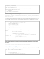
A simple example of an SVG file animating two images at the same time:
<svg width="600" height="400" viewBox="0 0 600 400" xmlns:xlink="http://www.w3.org/1999/xlink"
xmlns="http://www.w3.org/2000/svg">
<image xlink:href="item2608.jpg" x="100" y="100" width="50" height="50" id="img">
<animate attributeName="x" attributeType="XML" begin="0s" dur="1s"
fill="freeze" from="100" to="250 "
restart="whenNotActive" id="firstAnimation" />
<animate attributeName="width" attributeType="XML"
begin="firstAnimation.end" dur="1s" fill="freeze"
29
from="50" to="250" restart="whenNotActive" />
<animate attributeName="height" attributeType="XML"
begin="firstAnimation.end" dur="1s" fill="freeze"
from="50" to="250" restart="whenNotActive" />
</image>
<image xlink:href="item2608.jpg" x="250" y="100" width="50" height="50" id="img2">
<animate attributeName="x" attributeType="XML"
begin="0s" dur="1s" fill="freeze" from="250"
to="0 " restart="whenNotActive" id="firstAnimation" />
</image>
</svg>
Source code 1: Example using SVG. Two images are loaded and their attributes are "animated". The first image is moved
and stretched, the second image is moved along the x-axis.
This example shows that the animation functions are really high level. With a given start and
endpoint, begin time and duration it is possible to animate the objects. The animation can be the
XML attribute types such as height/width/x/y, but also CSS attributes for styling.
The Batik toolkit (The Apache Software Foundation, 2002) provides an interface to SVG in Java, which
might become handy once we want to integrate SVG into the Java project files.
With SVG, the animation of objects on the screen is significantly easier than with any other technique
discussed on this page. Furthermore is the XML format easy to understand and even without the
Batik toolkit easy to create with a Java program.
The main disadvantage is the lack of animation support in displayed objects. With Flash, the different
object states can be expressed in several keyframes with a label. In SVG, a new image could be
loaded through Java Script or an animation. The Flash approach also makes it possible to create a
keyframe an start an animation on that point. This could be accomplished with animated graphics,
like an animated GIF, but this is not support in SVG.
To add animated GIF graphics to a SVG file, BaKoMa TeX SVG Generator (Malyshev, 2006) can be
used:
However, importing GIF files may produce undesired rasterisation artefacts depending on resolution
of target display. In fact, importing animated GIF files is implemented via importing multi-page
Postscript. The way is: GIF2EPS import filter generates multi-page Postscript, such that every page
includes subimages extracted from GIF file. So, if you familiar with Postscript, using multi-page
Postscript is a simple and powerful way for creating animated scalable graphics.
Even with animated GIF files, the animation of simple objects on the screen would cost more than in
Flash.
Conclusion
After considering the above presentation methods, we have chosen for Flash. First of all, JOGL and
Panda3D are overkill for our project. We are looking mainly for a 2D presentation technique;
implementing 3D engines would cost a lot of time. This cannot compete against the advantages in
realism 3D might achieve.
Both SVG and Flash are good opportunities for the generation of movies. The simple XML input of
SVG is very interesting, but the lack of more sophisticated animations weights heavier. Flash is a bit
longer on the animation market then SVG has been and offers much more complex opportunities.
30
With the help of ActionScript, it should not be that hard to create a simple XML interface to these
functions. Thus, our project will contain a Flash presenter by default.
6.3.3
Flash presentation
Communication between Java and Flash
The main part of this project is implemented in Java. The director gives the presentation layer a
representation of the plot that is suitable for presentation. The presentation translates this
representation to a Flash movie. During our development cycle we had to choose between two
possible implementation techniques:
-
The presentation layer will produce an Action Script file that performs the needed actions for
presentation;
The presentation layer will produce an XML file that can be interpreted with Action Script.
Action Script translates the XML to the appropriate presentation actions.
The first approach removes the need for an intermediate XML representation of the film script. To
implement this approach Flash must be able to load external Action Script on runtime. After some
research we found out that this is not possible. If we had chosen to use this approach nevertheless,
the typical use case would be to copy/paste the generated code into a Flash movie and export the
movie. Therefore any person that wants to translate a plot to an animation would need an
installation of Flash Studio. This obviously would not make our program very user-friendly and the
user would need to install a large software package.
The second approach has the disadvantage of an intermediate XML structure. This might be a
problem when you try to sent the whole film script to Flash in XML format; since this would require
us to code a large portion of our work in Action Script, a less expressive language than Java. We
solved this problem by defining a very low level XML format and doing all calculations on the script,
like timing and resource selection in Java.
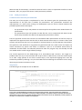
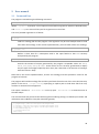
Xml format
The following is an example of such an XML file:
<movie>
<scene id="79" bgcolor="0x00CC00">
<library>
<object id="8393" clip="file.swf" x="0" y="0" opacity="100"
scale="100"/>
<sound id="snd1" sound="resources/sounds/ehet.mp3"/>
</library>
<timeline>
<animation object="8393" type="walk" starttime="0" />
<hear object="snd1" starttime="0" duration="620" />
<change object="8393" starttime="0" duration="5" x="1" y="2"
scale="60" opacity="50"/>
<change object="79" opacity="0" duration="6" />
<text object="subtitle" starttime="300" duration="200">bla</text>
</timeline>
</scene>
</movie>
Source code 2: Example XML file generated and used by the Flash presenter. The movie clip file.swf is loaded and
displayed in the scene. Furthermore a sound-clip is loaded and played. The timeline contains commands that affect the
objects in the scene. In this case a specific animation (walk) is started in the movie clip. Additionally several properties of
the object are animated and a subtitle text is displayed.
31
A Scene is a root object for all objects in that particular scene. This way we can perform camera
actions on the entire scene (like shaking the camera or fading out). Scenes have a background colour.
If a background image is required this image will be an ordinary object with a low Z-value.
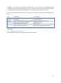
The Z-order is determined by the order of the objects in the library section. The following tags are
used:
Tag
Attributes
Description
object
sound
change
animation
hear
[id,x,y,scale,opacity]
[id,sound]
[object,start,duration,x,y,scale,opacity]
[object,starttime,duration,type]
[object,starttime,duration]
Define an object.
Defines a sound.
Change a property of an object
Animate an object.
Plays a sound
text
[object,starttime,duration]
Shows the specified text on screen.
Table 2: Tags used in the XML source file for the Flash presenter. The object attribute of the last four tags references the
id of an object.
6.3.4 Design of flash presenter
The image below shows the overall design of the flash presenter.
32
Figure 15: Design of the flash presenter, Java part. A FlashMovie consists of multiple scenes. The scenes in turn contain
displayable (and hearable) objects and a timeline that describes the events that happen in the scene.
The flash presenter is comprised of three parts; the commands, the resources and the objects that
are used for XML serialisation.
The commands
To make our framework as extensible as possible we used the Command Pattern. Each Action object
generated by the director is handled by a certain command. For example the MovementCommand
handles WalkAction and RunAction (which is a subclass of Walk Action). If at a certain point new
Actions need to be made, one can easily add those and a new command class to our existing
framework.
The resources
An important idea that influenced our ResourceManager is that of what we call fall-back. This
happens when the director wants to see a certain animation or object that does not exist. Simply not
showing an object greatly reduces the understandability of the story, so we show a more abstract
representation of it with a text box noting what it represents. This works very well, because the
fabula defines a hierarchy for every Object. For example Red -> Girl -> Person -> Animal -> Thing; if
we do not have a resource showing Red, we can simply show a girl with the text "Red" above it. This
doesn't only work for showing objects, but also emotions and actions. To make this work in the Java
33
part of the Presenters, it needs to know which Resources are capable of showing which emotions and
actions. We solved this by making a resources.xml with all the required data that is loaded by the
ResourceManager and then stored in ObjectResource, SubObject and Clip. The above mentioned
commands check if the specified actor can do a certain action and make sure that the fall-back
actually happens when it can't.
The XML objects
A movie contains several scenes. A scene again contains primarily two types of objects: the library
objects (FlashObject, FlashSound) are resources used by the scene, the timeline objects
(FlashTimelineObject) represent changes in the course of time during the scene.
FlashRefTimelineObjects have a reference to a specific FlashObject in this scene, whereas the
FlashTextChange and FlashPlaySound time line object do not. FlashPlaySound references a sound in
the library and FlashTextChange is used to change the subtitle or display a fallback message. It is
interesting to note that the FlashScene is a FlashObject itself, which allows us to change the
properties of the scene itself quite transparently.
6.3.5
Flash movie and ActionScript Design
Figure 16: Class diagram of the ActionScript part of the Flash presenter
The second part of the Flash presenter is implemented in ActionScript 3.0. There is one main movie
file that contains a reference to several ActionScript files. Editing the behaviour of the can be done by
editing these files and recompiling the Flash movie.
The Movie class will load the external XML file provided as input by the Java part of the Presenter.
For every object in the XML file, it loads the appropriate resource from the file system.
The system contains two queues, namely the ReadyQueue and the RunningQueue. The first contains
all the actions defined by the XML file, items in this queue are on hold until the current time is equals
the start time of the action. Once an action can be performed, it is enqueued in the second queue. It
will stay there until the end time is reached.
While an action is in the RunningQueue, it can perform animation actions according to its
parameters. The animate method is called on a fixed interval.
The IMovieController interface is used to control so called 'sub-movies', which we will discuss in the
next section.
34
For example, the flash movie for Little Red Riding Hood might consist of several smaller movie files
(i.e. her head, her body, her shoes). This can be used to switch her outfit at runtime without having
to create a new head for each outfit. The code to switch sub-movies at runtime unfortunately has not
been implemented yet, but the system has been completely prepared for this.
All flash movies used in the system must implement this interface. The presenter will just call
startAnimation() on little red riding hood's movie, without any knowledge of sub-movies contained in
this movie. This movie has the responsibility to either perform the requested animation itself, or
relay the request to one of its sub-movies.
6.3.6
Controlling an external movie clip
Introduction
The entities in our flash movies are themselves swf-files which may contain different animations and
again "submovies" with their own animations. A human can for example consist of a body and head.
This makes is possible to put a smile animation on the head, while playing a ‘run’ animation on the
body. This features tackles the problem of creating a animation for every possible combinations of
animations.
The main flash program does not know anything about the structure of the resources and whether of
not they contain sub-movies. However, some actions in the XML might trigger an animation. To
control the animations of sub-movies transparently, all resources that need to be controlled have to
implement a common interface that is well-known to the main program.
In the current version of the system, not all code for this feature is implemented. We will discuss the
implementation of this feature in the following sections.
The sub-movie
The sub-movie is primarily described in two files:
1.
2.
The .fla file that contains and arranges all elements of the movie: images, sub-movies etc.
A document class that implements a common interface to interpret animation commands.
The .fla file has to use version 3 of ActionScript in order to work with our system. The most crucial
setting is the document class to use. Per default, when a swf file is loaded, an instance of the
MovieClip class is created through which the flash application that loaded the movie can control it.
However, with the document class it is possible to define a class (which has to derive from
MovieClip) that should be instantiated instead. In our case we can use this property to provide a
class that derives from MovieClip and implements our IMovieController interface.
Currently IMovieController only defines one function. Given the name of an animation the
implementing class has to decide what to do.
Example
The example describes the "little red riding hood" submovie. The movie contains one child-movie,
"Head", which contains the head of the character. The body and an instance of the Head-symbol
have been dragged to the canvas.
Frame 1 of file red-body.fla contains the following ActionScript code. It loads the head for Red Riding
Hood and places it on the canvas.
35
stop(); // do not advance to second frame
// load content of child "Head"
var loader:Loader = new Loader();
var file:String = "resources/red/head-default.swf";
loader.load(new URLRequest(file));
loader.contentLoaderInfo.addEventListener(Event.COMPLETE, onMovieLoaded);
function onMovieLoaded(event:Event):void
{
// assign result
Head = MovieClip(loader.content);
addChild(Head);
}
Source code 3: Loading the head of Little Red Riding Hood
Note: resources are always accessed relatively to the main movie, this is why resources/red/headdefault.swf is used here.
The following ActionScript represents the document class that needs to be assigned to the movie clip
in order to work properly. It contains a startAnimation implementation for changing the sub-movie.
package { // create in root package
// imports used (primarily) by the frame 1 code
import flash.display.MovieClip;
import flash.events.Event;
import flash.display.Loader;
import flash.net.URLRequest;
// The interface
import infinity.IMovieController;
public class Red extends MovieClip implements IMovieController {
// Has to be public. Flash links the "Head"-object on the canvas to this
variable.
public var Head : MovieClip;
// implementation of the interface
public function startAnimation(name:String) : void{
// in our case, only the "sad" animation is recognized and
forwarded to the
// head sub-movie.
if(name == "sad"){
Head.gotoAndPlay(name);
}
}
}
}
Source code 4: The movie of Little Red Riding Hood implements IMovieController. The Flash presenter will be able to
pass the name of an animation to the movie object. The movie can then transparently do whatever is necessary to play
that animation.
In our case, the red-body.fla movie is exported to resources/red/default.swf.
Code in the presenter main programme
The animation-function in the Animation class is responsible for animation-actions. The following
code-snippet shows the part of that function that is related to the interface.
public function animation(clip,params,endTime) {
//...
var animationName:String = // ...
// try to access the clip as a movie controller
36
// (which knows how to interpret an animation name)
var controller = clip as IMovieController;
if(controller != null) {
controller.startAnimation(animationName);
} else {
debug("Cannot start animation " + animationName +
", object is not IMovieController");
}
// ...
}
Source code 5: The Flash presenter checks whether the movie supports IMovieController. If so, it passes the name of the
desired animation to the movie object. As a fallback mechanism, the presenter could call the method gotoAndPlay on
the movie, which directly starts a given key frame.
As shown the main programme does not know about the document class or any internal structure of
the animated clip. It only tries to access it as an IMovieController and forwards the animation-call
through the startAnimation method.
6.4 Discussion on the design
The previous chapters contain the design of our system based on the requirements and problem
analysis. In this section we will discuss the design by examining the requirements.
One of the more important requirements, besides the basis requirements of translating the fabula,
was the extensibility and replaceability of the subsystems. Creating a visual representation of a story
is liable to personal conceptions; somewhat comparable to the personal touch a director puts in his
movies in real-life. For this, we created several small replaceable subsystems, like the Analyser,
Cutter and Emitter. Adding new fabula elements or changing the style in which the movie is played is
easy to achieve by adding a new implementation or class. Unfortunately, our prototype is not
completely finished, but we are really satisfied about the framework we created. It shows enough
potential for future development.
The choice for Flash as a default presenter was very good. By creating a low-level XML structure as an
interface to the Flash movie, the Flash and ActionScript code is limited without a breakdown of
features. The XML structure might even become handy in other projects.
Most requirements stated earlier in this document are met. For example, primary requirement 2.6 is
not completely met, because there are no camera actions available in the prototype. However, the
design is ready to support these actions.
In the requirements is also stated that the system should make assumptions about missing
information in the plot. We found out that these assumptions are mostly derived from knowledge
within the plot. Guessing what the intention of a phase in the plot might be did not occur, which
might be a consequence of creating the test fabula by ourselves.
7 Test Plan
In this section we will first describe the test methodology we decided to use at the start of this
project by presenting our original Test Plan. We will then discuss our experiences during the project
with regards to these test methods.
37
7.1 Approach
We use an agile approach in this project, so this test plan is written using the agile approach
guidelines at (Wells, 2006).
7.1.1 Write unit tests before writing code
"Creating a unit test helps a developer to really consider what needs to be done. Requirements are
nailed down firmly by tests. There can be no misunderstanding a specification written in the form of
executable code."
We will use JUnit to automate the execution of the unit tests.
7.1.2 All code must have and pass unit tests
All code must pass a system-wide unit test. Untested code (or code without a unit test) cannot be
uploaded to the repository. However, trivial getter and setter methods may be omitted.
7.1.3 Pair programming
Pair programming significantly improves the quality of the code. Don't write code on your own unless
you have severe scheduling problems.
7.1.4 Acceptance tests
Acceptance tests are black-box system tests. The acceptance tests are created for each use case and
preferably automated, so they can run often. If an acceptance test fails a unit test is created to
detect this bug in the future.
7.1.5 No code reviews
Contrary to what is written in the project plan, we will not use code reviews. (Kubit, 1999) points out
that code reviews are generally counterproductive, as they rise stress levels and provoke a climate of
personal criticism. Pair programming will be used as substitute.
8 Test Results
8.1 Post-project evaluation of test plan
8.1.1 Writing unit tests before writing code
This kind of policy is definitely useful for ensuring that all code has a unit test (but see the section
below). It also ensures that plenty of thought is put into the design process.
On the other hand, this kind of policy may appear to conflict with the use of mostly-empty classes as
a design tool. Although UML is the accepted tool for high-level design, in some cases code can reveal
problems that our UML editor would not show.
8.1.2 All code must have and pass unit tests
While very useful for ensuring the correctness of many of the basic parts of the project, we found
that some of the core algorithms for this project (namely the Analyser and the Cutter) were very hard
to test in the way we had envisioned. This is for several reasons:
-
Due to the complexity of the problem these two parts need to solve, the precise definition of
what they needed to do was adjusted through the project.
38
-
The input and output for both components is large and complex, making writing a single test
case a lot of work
Due to the complexity, the number of test cases which needs to be handled is quite large
Due to these problems, we decided to test these components mainly by testing the complete
program (integration tests and acceptance tests).
We remain convinced that for the maintainability of this project, following our original test plan
would have been best. Unfortunately this would have required much more time than we had
available, and we believe that in the course of any project tradeoffs of this kind are unavoidable.
8.1.3 Pair programming
Pair programming really proved itself to us as a valuable element of the development process,
especially when low-level design decisions need to be made on the spot. We found pair
programming is an effective guard against insufficiently thought out short-term solutions. It also
speeds up working on as complex a code base as our project has become, since two people always
know more about the code than one.
We also found that pair programming was indeed an excellent replacement for code reviews.
Reading source code looking for errors is never as productive as using or working on this sourcecode
with another member of your team to discuss its details with. Over the course of the project, we
found that pair programming (and mixing up the pairs regularly) contributed a lot to everyone's
understanding of the entire program.
8.1.4
Unit test reports
Every time a new revision was committed to the revision control
system the program was automatically built, all unit tests were run
and the results were mailed to all group members. This system
proved invaluable in keeping up to date on the status of the
project.
The fact that everyone was immediately alerted when something
went wrong with the latest build or tests significantly reduced lost
Figure 17: Unit tests run from within
Eclipse.
development time due to people committing erroneous code that
may not immediately have been noticed otherwise.
8.1.5 Acceptance tests
Acceptance tests consisted mainly of two test fabulas, test.trig and fabula.trig. The first is meant as a
basic test fabula and is in fact also used in the unit tests.
The output of produced for these two fabula's was regularly used by us in evaluating and debugging
the program. Due to time constraints we did not automate the running of the acceptance tests,
unlike the unit tests.
39
9 User manual
9.1 Command line
The program is started using the following command:
java -cp ./target/classes infinity.GenerateMovie [arguments] fabula.trig
Where [arguments] represents a set of optional command line arguments which are defined below,
and fabula.trig is the name of the input file to generate a movie from.
The set of possible arguments is as follows:
--ontology [file]
-o [file]
Loads an ontology file into the program. This argument may be used multiple times to load
more than one ontology. In the current implementation, you must load at least one ontology.
--prefix [prefix]=[uri]
-p [prefix]=[uri]
Defines a short alias for a namespace used in the input fabula so that it is correctly
interpreted by the program.
-v [debug level]
Controls the amount of output generated by the program. Acceptable values are TRACE,
DEBUG, INFO, WARN, ERROR, or FATAL. These values are not currently guaranteed to display
only the type of messages implied by their name, but a decrease in the amount of messages
with later values is likely.
Note that in the current implementation, at least one ontology must be specified in order for the
program to function!
The program will load the ontology files and the input fabula from the root of the Java class hierarchy
(which in this case is ./target/classes). Specifying an explicit path to load these files from may
work but is untested and unsupported.
The output is written to ./data/movie.xml. You may open ./data/movie.swf to view the movie in
the Flash Player.
The command line that processes the fabula.trig file used during testing is as follows (line breaks and
indentation were added for clarity but should be ignored):
java -cp ./target/classes infinity.GenerateMovie
-p graphs=http://www.owl-ontologies.com/Graphs.owl#
-p fk=http://www.owl-ontologies.com/FabulaKnowledge.owl#
-p swc=http://www.owl-ontologies.com/StoryWorldCore.owl#
-o FabulaKnowledge.owl
-o StoryWorldCore.owl
fabula.trig
40
9.2 Input files
9.2.1 Ontologies
There are two OWL ontology files currently being used by our project.
The first is FabulaKnowledge.owl which models relationships like cause and effect, knowledge and
perceptions, and goals and outcomes. It is based on (Swartjes, 2006).
The second is StoryWorldCore.owl which is used to model some more practical things like objects,
actions, locations and containers. It is based on (Uijlings, 2006).
9.2.2 Fabula
The fabula input is provided in the form of RDF dataset in TriG format (Bizer, 2005). Currently this file
is generated either by Ivo Swartjes' Fabula Editor or using a plain text editor, but it is meant to be
generated automatically in the future.
The overall structure of the fabula is best described in the document (Swartjes, 2006) mentioned
earlier.
9.3 Resource files
The Flash movie is produced using a collection of images, movie clips and sounds. These are called
the resources, and they can be found in the directory ./data/resources.
9.3.1 The file resources.xml
For a resource to be useable, it must be described in resources.xml which is located in the root of the
resources directory. We will briefly describe the format of this file here by describing a short
example.
<resources>
<object name="girl" width="100" height="100">
<subobject name="head">
<clip name="sad" duration="100" />
</subobject>
<subobject name="default">
<clip name="strike" duration="100" />
</subobject>
</object>
<object name="forest" width="400" height="300">
</object>
</resources>
Source code 6: Example content of resources.xml
This example defines an object with the name "girl". This resource definition will probably be used to
represent a character. It defines two animations: one global animation named "strike" and an
animation "sad" that only applies to a subcomponent named "head". This subcomponent will have to
be defined in the Flash file that represents this object, but more about that later. Note that the same
"girl" resources may in fact be used to represent multiple characters in a scene if the presenter
decides this object is the best representation for them.
The other resource definition in this file simply defines an object with no animations. This object
looks like it will be used as a backdrop for a forest scene.
41
9.3.2 Directory structure
Resource files are located in subdirectories of the resources directory. Every object has its own
directory. For example, the file which make up the "girl" object would be stored in the directory
./data/resources/girl.
The main file for a resource is named default, with an extension depending on the file type. For
simple objects without animation, the main file is simply a PNG image file named default.png.
For more complex objects, the main file is a Flash movie named default.swf. This movie file contains
the logic to start the proper animations for its sub-objects.
9.3.3 Complex objects (.swf)
Objects which support animations need to be implemented as a Flash 9 .swf movie file. This movie
object must handle the animations named in the resources.xml file by implementing the
IMovieController interface. For more details see the chapter about the design of the presenter.
9.3.4 The main Flash file (movie.swf)
This is the main flash movie. It contains the logic to read the movie.xml file, load the needed
resources, and then display the movie. Note that this file does not need to be changed when a new
movie is generated. This was a deliberate design decision, since we didn't want to require a Flash 9
license just to use our application.
9.3.5 Mapping of fabula elements to resources
In principle, fabula elements are mapped to Flash resources of the same name (namespace prefixes
are simply ignored at the moment).
When no resource matching a fabula element can be found, there are several ways a replacement
resource may be selected by the Presenter.
-
-
Type hierarchy - For example, when no representation can be found for the emotion
"furious" the presenter may display the animation for its superclass "angry". Note that the
usage of the ready-made ontologies somewhat limits this mechanism, since the class
hierarchy is anything but exhaustive.
Text fallback - Anytime no perfect representation of a fabula element can be found, the
presenter displays a text representation of this element. For actions and emotions, the text is
displayed near the affected object. For global or unknown elements, the text is simply
displayed at the bottom of the screen.
9.4 Known limitations
9.4.1
-
Fabula
When characters have contradictory perceptions the results produced by our application are
undefined.
9.4.2
-
Visualisation
Complex actions like characters carrying objects are not currently implemented, but should
be possible without significant changes to the design.
When things happen simultaneously in two different places the visualisation does not make
this clear.
-
42
-
Location transitions are currently only shown as characters walking offscreen and then back
onscreen in the new location.
Because the timestamps in the fabula are treated as only indicating relative positions of
events the precise timing of events becomes a non-trivial problem. Our current
implementation is pretty decent, but unexpected results are still likely.
9.5 Example
This section contains a step-by-step walk through through the system. We will cover all aspects of
the system by a simple example.
9.5.1 Example fabula
The example plot we will be using in this section, contains the following elements:
-
A character ‘Red’, initial at location ‘Forrest’ (timecode: 0)
A location ‘Forrest’
A location ‘Dessert’
An action ‘walk to Dessert’, with relative timecode: 100
An emotion ‘Happy’ on character ‘Red’, with relative timecode: 200
9.5.2 Director
The director should read out the input files and generate a film script according to the information
stored in these files. It will perform the following steps:
-
-
-
-
First, it loads all the entities in the plot into memory, translating entities to instances of the
Entity class. In a second iteration, it loads all properties belonging to an entity and stores
them in instances of the Property class.
The Analyser performs the second step. It receives the list of entities and shall put these
entities in the time-space grid. This is achieved in several small steps:
o First, all entities that have a fk:time property are put in the grid. For these entities,
no estimation of the time of occurrence is needed. In our case, both action entities
stored in our example fabula are added to the grid.
o Secondly, the analyzer iterates through all entities with a direct time code found in
the previous step. It tries to find out if there are any entities or graphs that are in
some way connected to these entities. If so, it adds these entities to the grid,
assuming that the time of occurrence will be equal to the referencing entity. The
‘Red’ and ‘Forrest’ entities in our example have a locatedAt reference to each other.
o The last step in the analyzer, is finding the locations of entities. Inspecting properties
like locatedAt and move actions does this. For example the knowledge that ‘Red’
should be at ‘Dessert’ after moving to it at time 100 is now discovered.
Next, the cutter will create appropriate scenes in the plot. This is done by examining the
time-space grid. In our example, two scenes are discovered, mainly because of the different
locations the plot is situated in.
In the last step, the director will translate all entities to appropriate film script actions. The
director tries to find an emitter for the entity and performs the actions stored in the emitter.
For example the ‘Walk’ entity in our fabula will be translated into a WalkAction instance in
the film script.
43
-
At this point, the director has produced the film script, which is a linear version of the plot
containing actions that need to be performed by the presenter.
9.5.3 Presenter
The second part of the system is the presenter. While running the prototype, the two parts of the
system are tightly coupled. Action from the user is not needed until the FlashPresenter generates the
XML file. The Java part of the presenter performs the following steps for each action in the film
script:
-
First, the presenter tries to find a command that fits the type of action.
This command is executed. It depends on the type of command which actions are taken next.
o For example the WalkAction is connected to a MovementCommand. The
MovementCommand creates a new XML node representing the movement on the
screen.
Once the presenter detects an EndOfMovieAction, it writes the XML file to the file system. The XML
file can then be read into the Flash movie. In ActionScript, the action again takes several steps:
-
-
First, it is enqueued in the ReadyQueue.
Once the start time of the action is equal to the current time, it is moved to the
RunningQueue. From then on, until the end time of the action, every time interval the
animate method is called.
The animate method will perform an action on screen depending on the type of action. For
example our move action could for example say that Red should move from x=50 to x=150 in
6 seconds. If the screen is updated every second, in each interval Red should move (150-50) /
6 16 pixels to the left. Once the 6 seconds are past, the item is removed from the
RunningQueue and therefore not executed anymore.
This last step performs the actual visual presentation of the plot on the screen of the user.
9.6 Extending the system
It is possible to extend the system in several ways to add for example new fabula elements or
actions. This section will describe how this can be achieved.
9.6.1 Adding new fabula elements / actors
The first change you might want to make, are new resources for new actors or sites in the story. To
add a new resource, the artwork should be placed in the resources folder. In addition to that, the
new resource should be added to the resources.xml file. This XML should be self-explaining.
The artwork can be of any type of image supported by Flash. This means jpg, gif and png for static
images and swf files for movies.
9.6.2 Adding new actions
In some cases, it might be necessary to add new actions to the application to support new kinds of
fabula actions. This can be done with the following steps:
-
Add a new emitter class that applies on the entity and translate the entity into one or more
actions in the film script.
If new actions are needed, add the action class to the film script.
44
-
To display a new action, a new command should be added to the FlashPresenter to translate
the action into one or more actions in the XML file.
45
10 Discussion
10.1 Project status
Unfortunately we were unable to complete the whole project within the specified time. A small
subset of the available fabula actions will be accepted by the system and correctly animated. Cutting
the plot into logical scenes also works well, but there is room for improvement.
We did also manage to incorporate all extensibility features and a fully functional Flash presenter
component. Script commands that have no visual representation are not automatically displayed as
text but the ‘infrastructure’ for displaying these kinds of text is in place.
Support for changing representations of characters and objects at runtime has been prepared in all
parts of the system but has not been fully implemented. Support for playing audio was also
implemented.
10.2 Recommendations for Future Work
10.2.1 Fabula and ontologies
- Extending the available ontologies with more levels in the type hierarchy would present us
with more opportunities to re-use Presenter resources. For example, it is useful to know that
a Princess is also a Woman in case no image of a Princess is available.
- In the case of conflicting perceptions in the fabula, there is no way to determine (or
represent) the objective "truth". Whether this is in fact a problem is a matter for debate.
10.2.2 Director
- A more elegant parser might be possible by tighter integration with Jena. A Reasoner which
knows about the concept of time in general and its significance in the FabulaKnowledge
system in particular could possibly replace our Analyser.
- Introducing the concept of a protagonist or main character would enable the director to
decide more intelligently which parts of the fabula are important.
- Introduction of absolute times or duration for actions would benefit the system a lot. It is
currently very difficult to determine when an action ends.
10.2.3 Presenter
- Using an open-source flash compiler will allow a lot of complexity to be removed from the
flash code. We would no longer have to build the entire animation in ActionScript since
recreating the swf file every time the movie is compiled is then an option
(http://osflash.org/open_source_flash_projects)
- We currently don't come close to using the full potential of the Flash format, mainly for the
reason that we did not have the time to create the resources. We also currently do not use
things like camera actions (zoom, follow), complex scene transitions and sound effects,
because we did not have time to implement the logic that decides when to use them.
46
11 Final thoughts
Although the project is not fully completed, we are satisfied with the results: the project can be easily
used for further work, and we have learned a lot about ontologies, storytelling and animation. The
project was also a good exercise in software engineering techniques.
On the organisational/teamwork side, we experienced what working in a software development
team is like. Also, the approach and tools we had chosen for this project turned out to be successful.
47
12 Glossary
The following special terms are used in this report:
Fabula
Description of everything that exists and happens in the world of the specific story. This
includes actors, environments and actions, but also reasoning, emotions and goals.
Plot
A single thread of the story that describes all states, actions etc. that belong to this part of the
story.
Ontology
In the field of Virtual Story Telling the ontology describes all concepts that can be part of a
fabula. Typically an ontology describes entity classes (for example: human, action, object,
emotion etc.) and properties (for example: located-at, belongs-to, is-a etc.). Therefore, the
ontology can be seen as the vocabulary a fabula is made of. The classes are instantiated in the
fabula. For example, the class Human might be instantiated as the entity "Little Red Riding
Hood". The properties are attached to the entities.
trig-file
A file with extension .trig that contains a fabula.
owl-file
A file with extension .owl that contains the ontology used by a trig-file.
Film script
A list of commands that contain a linear description of anything that the presentation module
(presenter) needs to present a plot to the user.
Director
The part of the system that translates a fabula network to a linear film script
Presenter
The part of the system that visually presents a film script generated by the director.
Direct visualization
A presenter displays the content of the film script at the moment that the director passes the
script to the presenter. (Example: a simple presenter that simply dumps the commands to the
console)
Indirect visualization
A presenter converts the commands in the film script to a format that is specific for this
presenter. Only after the complete transformation the results are shown. (Example: a
presenter that converts a film script to a script language that is interpreted by a visualization
engine).
Graphical presenter
The product will be delivered with at least one presenter that can display a film script
graphically.
48
Scene
A scene is defined by a number of events that occur at one place during the course of some
range of time.
Dom
Document object model. An in-memory representation of a hierarchical document such as
XML. Objects are used to represent nodes in the document. These objects are easier to
manipulate than the raw (textual) data using object oriented techniques.
Agile Software Development
A "lightweight" software development methodology that facilitates short development cycles,
frequent communication and evolutionary design.
49
13 References
Adobe. (2007). Adobe Flash CS 3. Retrieved from Adobe: http://www.adobe.com/products/flash/
Bal, M. (1997). Narratology: Introduction to the Theory of Narrative (2nd ed.). University of Toronto
Press.
Bizer, C. (2005, June). The TriG Syntax. Retrieved from Freie Universität Berlin: http://sites.wiwiss.fuberlin.de/suhl/bizer/TriG/
Carnegie Mellon University. (2002). Panda3D. Retrieved from Panda3D: http://panda3d.org/
CollabNet. (2007). Java bindings for OpenGL. Retrieved from java.net: https://jogl.dev.java.net/
Damiano, R. L. (2005). Formal encoding of drama ontology. In Lecture Notes in Computer Science
3805 (pp. 95-104).
Jena. (n.d.). Jena. Retrieved
http://jena.sourceforge.net/
from
Jena
–
A
Semantic
Web
Framework
for
Java:
Kubit, T. (1999). Code Reviews Considered Hurtful. Retrieved from Extreme Programming: A gentle
introduction.: http://www.extremeprogramming.org/
Lilley, C. (2007). Scalable Vector Graphics. Retrieved from W3C: http://www.w3.org/Graphics/SVG/
Louchart, S. A. (2004). Narrative theory and emergent interactive narrative. Int. J. Continuing
Engineering Education and Lifelong Learning 14 , pp. 506-518.
Malyshev, B. K. (2006). BaKoMa TeX. Retrieved from BaKoMa TeX: http://www.bakomatex.com/
Sgourus, N. (1998). Dynamic generation, management and resolution of interactive plots. In Artificial
Intelligence (pp. 29-62).
Sun Microsystems. (1999, April 20). Code Conventions for the Java Programming Language. Retrieved
from Sun Developer Network: http://java.sun.com/docs/codeconv/
Sun Microsystems. (2004). Javadoc Tool Homepage. Retrieved from Sun Developer Network:
http://java.sun.com/j2se/javadoc/
Swartjes, I. &. (2006). A Fabula Model For Emergent Narrative. Proceedings of the Third International
Conference on Technologies for Interactive Digital Storytelling and Entertainment (TIDSE 2006),
Lecture Notes in Computer Science 4326 (pp. 49-60). Springer-Verlag Berlin Heidelberg.
TDD. (2007). Test-driven Development. Retrieved from Wikipedia: http://en.wikipedia.org/wiki/Testdriven_development
The Apache Software Foundation. (2002, 2007). Batik Java SVG Toolkit. Retrieved from Apache XML
Graphics Project: http://xmlgraphics.apache.org/batik/index.html
Trabasso, T. V. (1989). Logical necessity and transitivity of causal relations in stories. Discourse
Processes 12 , (pp. 1-25).
50
Tuffield, M. M. (2006). Ontological approaches to modelling narrative. Proceedings of 2nd AKT DTA
Symposium.
Uijlings, J. (2006). Designing a Virtual Environment for Story Generation. Doctoral Thesis Artificial
Intelligence - Knowledge Technology, Faculty of Science .
Virtual Story Teller. (n.d.). THE VIRTUAL STORYTELLER.
http://hmi.ewi.utwente.nl/showcases/The%20Virtual%20Storyteller
Retrieved
Wells, D. (2006). A gentle introduction.
http://www.extremeprogramming.org/
Extreme
Retrieved
from
from
HMI:
Programming:
51