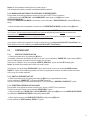
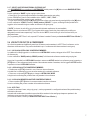
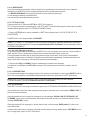
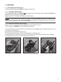
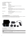
1
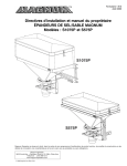
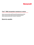
Peltor™ DECT-Com II™
The Sound Solution
User’s manual for DECT-Com II
DECT 1.8 GHz
QUICK GUIDE – Peltor DECT-Com II
Button
Function
[M]
Switch DECT-Com II unit on/off
Select function in the menu
[+] Increase the level of selected function
[–] Decrease the level of selected function
[M] & [+]
[M] & [–]
Switch DECT-Com II unit on as base
Switch DECT-Com II unit on as portable
[PTT1] Press twice to talk in conference 1
Press once to listen in conference 1
[PTT2] Press twice to talk in group 2
Press once to listen in group 2
PTT for external device in upper connector
[PTT3] Press twice to talk in group 3
Press once to listen in group 3
PTT for external device in lower connector
[+] & [–]
All call (short simplex transmission)
For latest revised full user’s instructions, please see www.3m.com/peltorcomms on the Internet.
Look in section “Rest of the world” and find “PDF LIBRARY”, where you can read or download multilingual information about the Peltor
DECT-Com II system!
(Fig. A)
Antenna
Function indication ring
Headset connector
[M] Mode
[+] Up
[–]Down
LED (Light Emitting Diode)
PTT1 Push-To-Talk 1
PTT2 Push-To-Talk 2
PTT3 Push-To-Talk 3
Attachment clip
1
INDEX
2
1
INTRODUCTION
2
2.1
2.2
2.3
2.4
2.5
2.6
MAIN UNITS
SWITCH A MAIN UNIT ON AND OFF
BASE/PORTABLE UNIT
PORTABLE UNIT
LOG IN TO OR OUT OF A CONFERENCE
MAIN UNITS CONTROLS
TECHNICAL INFORMATION, MAIN UNITS DC2811, DC2812, DC2815
3
3.1
3.2
POWER SUPPLY
BATTERIES
FIXED MOUNTED POWER SUPPLY
4
4.1
4.2
ANTENNAS
GENERAL ANTENNA
OMNI DIRECTIONAL VEHICLE ANTENNA
5
5.1
5.2
EXTENSION OF THE SYSTEM
EXTERNAL EQUIPMENT
REMOTE WIRELESS PTT
6
ACCESSORIES AND SPARE PARTS
7
APPROVALS
8
WARRANTY
9
PROGRAMMING DECT-Com II UNITS
PELTOR DECT-Com II
1. INTRODUCTION
Peltor™ DECT-Com II™ is a wireless duplex intercom system, operating on the 1.8 GHz DECT-frequencies, which are
license free in most countries.
The products in the Peltor DECT-Com II family offer simple and efficient wireless duplex communication with up to 9 active
users talking in full conference and additionally up to 40 listeners with possibility to quick “break in” to the conference. In a
system with more than 9 users any listening participant can change from listening to speaking. The earliest active speaker
will then be “degraded” to a listener in the conference and any other listener can follow, replacing active speakers in the
order “first in – first out”.
There are basically two versions of the DECT-Com II main unit; base/portable units and portable units. The portable units
work via a base unit. A base/portable unit can be either used as base or portable, alternatively.
Due to low power output and high frequency it is a short range communication system. The nominal working range is
approximately 250 metres outdoors in line of sight. The working range may be shorter due to actual conditions.
Read all of these instructions carefully before use and save for future reference!
Never modify or alter any product!
3M does not accept liability of any kind, be it direct or consequential (including, but not limited to, loss of
profits, business and/or goodwill) arising from reliance upon any information herein provided by 3M. The user is
responsible for determining the suitability of the products for their intended use. Nothing in this statement will be
deemed to exclude or restrict 3M’s liability for death or personal injury arising from its negligence.
2. MAIN UNITS
A Peltor DECT-Com II portable unit DC2811 is a personal
radio transmitter/receiver to which a headset should be
connected. Any Peltor headset with J11 connector wired
according to “Peltor standard” can be connected to a Peltor
DECT-Com II portable unit.
A Peltor DECT-Com II base/portable unit DC2812 is
a central radio transmitter/receiver, which is needed to
communicate all information from and to all portable units in a
DECT-Com II system.
A Peltor DECT-Com II extension base/portable unit
DC2815 is a central radio transmitter/receiver, equal to a
base/portable unit, but to which external equipment can be
connected to extend the DECT-Com II system.
Any Peltor headset with J11 connector wired according to
“Peltor standard” can also be connected to a Peltor
DECT-Com II base/portable unit.
2.1 SWITCH A MAIN UNIT ON AND OFF
g Switch a DECT-Com II main unit on by pressing the [M] button.
In a headset, connected to the headset connector on the unit, a voice confirmation “POWER ON” or “BASE, POWER ON”
is given and the LED (light emitting diode) is flashing, indicating that the unit is in SET UP MODE.
3
When a base unit is ready for use, a voice message “BASE, GROUP 1” is given. The LED on the unit is flashing slower.
When a portable unit is ready for use, a voice message “GROUP 1” is given. The LED on the unit is lit.
Notice: All units are always started in listen only mode in group 1.
2.1.1
SWITCH A MAIN UNIT OFF
g Switch a unit off by pressing and holding the [M] button for approximately 2 seconds.
A voice confirmation “POWER OFF” is given, the LED is unlit, and the unit is turned off.
2.2
BASE/PORTABLE UNIT
2.2.1
SWITCH A BASE/PORTABLE UNIT ON
g Switch a base unit on by pressing the [M] button.
In a headset, connected in the headset connector on the unit, a voice confirmation “BASE, POWER ON” is given and the
LED (light emitting diode) is flashing, showing that the base unit is setting up the system.
Notice: Initially, a base/portable unit is starting up as a base.
(See also 2.2.3 ALTERNATIVE OPERATION MODES OF BASE/PORTABLE UNITS below.)
After approximately 20 seconds, the system is ready and a voice message “GROUP 1” is given. The LED on the unit is
flashing slower, showing that the base unit is ready for use and portable units can be logged on.
(The LED can be switched off with use of special DECT-Com II software.)
2.2.2
SWITCH A BASE/PORTABLE UNIT OFF
g Switch a base unit off by pressing and holding the [M] button for approximately 2 seconds.
A voice confirmation “POWER OFF” is given, the LED is unlit, and the unit is turned off.
2.2.3
ALTERNATIVE OPERATION MODES OF BASE/PORTABLE UNITS
By different start-up sequences the base/portable main units can be set up to work either as a base or as a portable unit.
2.2.3.1
START THE UNIT AS A BASE UNIT
g Switch the unit on by pressing and holding the [M] and [+] buttons simultaneously for approximately 2 seconds.
In a headset, connected in the headset connector on the unit, a voice confirmation “BASE, POWER ON” is given,
confirming that the unit is started as a base unit.
After approximately 20 seconds, the system is ready and a voice message “GROUP 1” is given. The LED on the unit is
flashing slower, showing that the base unit is ready for use and portable units can be logged on.
(The LED can be switched off with use of special DECT-Com II software.)
A user with a headset connected in the headset connector on a base unit can also be participating in a DECT-Com II
conference, similar to a portable unit.
Notice: All units are always started in listen only mode in group 1.
Last used alternative (base or portable) is remembered between sessions.
2.2.3.2 START A BASE/PORTABLE UNIT AS A PORTABLE UNIT
Check that the actual base unit is switched on and ready!
g Switch the unit on by pressing and holding the [M] and [–] buttons simultaneously for approximately 2 seconds.
In a headset, connected in the headset connector on the unit, a voice confirmation “POWER ON” is given, confirming that
the unit is started as a portable unit.
After approximately 10 seconds, the unit is ready and a voice message “BASE #, GROUP 1” is given. The LED on the unit
is lit, showing that the unit is ready for use as a portable unit, and is logged on to base No. #.
(The LED can be switched off with use of special DECT-Com II software.)
4
Notice: All units are always started in listen only mode in group 1.
Last used alternative (base or portable) is remembered between sessions.
2.2.4 MAKE A BASE UNIT READY FOR PORTABLES TO BE REGISTERED
Each portable unit should be registered to a base unit to be part of a DECT-Com II conference.
g With the base unit in LISTEN-ONLY and VOLUME MODE, double press on the [M] button to enter
REGISTRATION MODE.
A base unit in REGISTRATION MODE is indicated by a voice confirmation “SUBSCRIPTION ON” and the LED flashing
slowly.
g When all portable units are registered to the base unit, exit REGISTRATION MODE by double pressing [M] button.
Notice: All main units are delivered open for registration from factory and a DECT-Com II system can be started directly
“out of the box” by first starting a base/portable unit as a base as described above and after that, all portable units,
sequentially and continually, as described above.
After the first turn off of the base unit, the configuration of the system is fixed and future change of units has to be handled
according to description above.
If your system is delivered pre-registered in a certain configuration by your Authorised Peltor DECT-Com II Dealer*), all
future registration has to be handled by your Authorised Peltor DECT-Com II Dealer*).
2.3
PORTABLE UNIT
2.3.1
SWITCH A PORTABLE UNIT ON
g Switch the portable unit on by pressing the [M] button.
In a headset, connected in the headset connector on the unit, a voice confirmation “POWER ON” is given and the LED on
the unit is flashing green, showing that the unit is logging on to the base.
When the unit is ready for use, a voice message “BASE #1, GROUP #1” is given and the LED is steady green.
Notice: All portable units normally start in listen only mode in group 1.
At first start up, a voice message “SEARCHING” is given. When a base is found a voice message BASE (number),
GROUP 1” is given. When restarting a portable unit, which is programmed to be able to work with more than one base, it
will try to log on to the last used base.
2.3.2 SWITCH A PORTABLE UNIT OFF
g Switch the portable unit off by pressing and holding the [M] button for approximately 2 seconds.
A voice confirmation “POWER OFF” is given and the LED is turned off.
If the unit is still searching for a base when switching off, a voice confirmation “WARNING, POWER OFF” is given.
2.3.3 REGISTER A PORTABLE UNIT ON A BASE
Each portable unit is registered to at least one base unit to be part of a DECT-Com II conference.
The unit is searching for bases. A voice message “SEARCHING” is given.
g With the portable unit in LISTEN-ONLY and VOLUME MODE, double press [M] button to enter BASE SELECT MODE.
A portable unit in BASE SELECT MODE is indicated by flashing LED.
g When a base is selected, exit BASE SELECT MODE by briefly pressing [M] button.
A voice confirmation ”BASE (number), GROUP 1” is given.
5
Notice: All main units are delivered open for registration from factory and a DECT-Com II system can be started directly
“out of the box” by first starting a base/portable unit as a base as described above and after that, all portable units,
sequentially and continually, as described above.
After the first turn off of the base unit, the configuration of the system is fixed and future change of units has to be handled
by your Authorised Peltor DECT-Com II Dealer*).
If your system is delivered pre-registered in a certain configuration by your Authorised Peltor DECT-Com II Dealer*), all
future registration also has to be handled by your Authorised Peltor DECT-Com II Dealer*).
(See also above 2.2.4 MAKE A BASE UNIT READY FOR PORTABLES TO BE REGISTERED.)
2.3.4 LOG ON A PORTABLE UNIT TO A BASE
There are two versions of log on:
1. At first power on (out of the box), the base unit will allow any portable unit to log on. (See 2.2.4 MAKE A BASE UNIT
READY FOR PORTABLES TO BE REGISTERED)
2. At any next start up you will automatically be logged on to the base.
When the log on sequence is finished, the LED on the unit is fixed green and a voice message “BASE (number), GROUP
1” is given, confirming that the portable unit is logged on as a listen-only to the base and group with the given numbers.
!
If no confirming message is given; check that the base unit is switched on and in range!
!
If the message “WARNING, SUBSCRIPTION EMPTY” is given; there is no base unit registered to log on to.
!
If the messages “SIGNAL LOW, OUT OF RANGE” are given; the portable unit has no connection with the base unit.
After approximately 20 seconds a message “SEARCHING” is given, indicating that the unit is searching for a base
unit. You may be too far away from the base, or the base unit is switched off!
When in contact with a base unit again; a message “BASE (number), GROUP 1” is given, confirming that the unit is
logged on to a base with the actual number.
2.3.5 LOG ON A NEW PORTABLE UNIT TO A BASE
If, later, another portable unit should be logged on to the base, the actual base unit must be set in REGISTRATION MODE
(see 2.2.4 MAKE A BASE UNIT READY FOR PORTABLES TO BE REGISTERED). The portable unit must be in SEARCH
MODE (see 2.3.6 SEARCH A BASE FROM A PORTABLE UNIT below.)
Notice: All main units are delivered open for registration from factory and a DECT-Com II system can be started directly
“out of the box” by first starting a base/portable unit as a base as described above and after that, all portable units,
sequentially and continually, as described above.
After the first turn off of the base unit, the configuration of the system is fixed and all future change of any units has to be
handled by your Authorised Peltor DECT-Com II Dealer*).
If your system is delivered pre-registered in a certain configuration by your Authorised Peltor DECT-Com II Dealer*), all
future registration also has to be handled by your Authorised Peltor DECT-Com II Dealer*).
2.3.6 SEARCH A BASE FROM A PORTABLE UNIT
g In BASE SELECTION MODE on a portable unit; double press on the [M] button to enter BASE SEARCH MODE.
A voice confirmation “SEARCHING” is given repeatedly, confirming that the unit is searching for active bases in range.
When a base is found a voice confirmation “BASE (number), GROUP 1” is given.
To find more bases, repeat this procedure again.
6
2.3.7 SELECT ANOTHER BASE FROM A PORTABLE UNIT
g In VOLUME MODE on a portable unit in LISTEN MODE; double press on the [M] button to enter BASE SELECTION
MODE.
A voice confirmation “BASE” is given, urging to select a base.
g Press [+] or [–] to cycle through the numbers of available bases and an auto setting
A voice confirmation is given for each available choice: “AUTO”, “ONE”, “TWO” …
Stop at your preferred base number (or auto, see below).
g Log on to the base by pressing the [M] button and return to listen only menu items by pressing briefly on the [M] button.
A voice confirmation “LOGIN” followed by “BASE (number), GROUP 1” is given, confirming that the portable unit is
logged on to the base with the given number as a listener in the given group.
If “AUTO” is chosen, the unit will log on to the base with the latest used base or the next available.
Notice: If there is more than one DECT-Com II system within range of each other, the portable units could be predesignated to certain bases respectively. Then, if the choice “AUTO”, the unit will log on to the first found of the predesignated bases.
(For programming DECT-Com II units, a special PC software is needed. Contact your Authorised DECT-Com II Dealer*) !)
2.4 LOG IN TO OR OUT OF A CONFERENCE
Up to 9 active speakers and additionally more than 40 listeners can be members in a DECT-Com II conference, on the
same base at the same time. They can be subdivided in up to 3 conferences with fewer members in each group.
2.4.1 LOG IN AS A LISTEN-ONLY CONFERENCE MEMBER
A portable unit is initially logged in to a conference as a LISTEN-ONLY member, taking part in the DECT-Com conference
as a listener only.
A voice confirmation “BASE (number), GROUP (number)” with the actual conference number and group is given.
At any time it is possible for a LISTEN-ONLY member to enter as an ACTIVE member in a conference group by pressing a
[PTT#] button. If the conference already consists of the maximum number of members, the first logged in ACTIVE member
is pushed out to be a LISTEN-ONLY member.
2.4.2 LOG IN AS AN ACTIVE CONFERENCE MEMBER
g Double press on [PTT #] to break in to one of the max. three conferences.
A double tone is confirming that you are an active member in the selected conference.
g Press once on the same [PTT #] again to change to LISTEN-ONLY MODE.
A single tone is confirming that you are a listen-only member in the conference.
2.4.3 LOG IN AS A MEMBER IN ANOTHER CONFERENCE GROUP
g Press on another [PTT #] button to become a member in another conference.
A tone is confirming that you are a member in the selected conference.
2.4.4 AUTO TALK
A system for maximum 9 users, using only group 1, can be programmed in a configuration where all the portables always
should be in talk mode.
Automatic talk mode makes it possible to ensure that all the members in the small group always are speakers in the
conference, as soon as they are in range of the base unit.
(For further information; contact your Authorised Peltor DECT-Com II Dealer*).)
7
2.5 MAIN UNITS CONTROLS
2.5.1 MODE
The MODE button [M] controls functions of the unit.
g Step forward through the MODE steps in the menu by pressing briefly on the [M] button.
Voice messages “VOX”, “MICROPHONE”, “VOLUME” are given respectively to confirm the actual mode.
g Step backwards through the MODE steps by double press on the [M] button.
Voice messages “MICROPHONE”, “VOX”, “VOLUME” are given respectively to confirm the actual mode.
g Use the [+] and [–] buttons to adjust the settings respectively.
Current settings are stored when the unit is switched off.
Notice: A double-press in VOLUME MODE and LISTEN ONLY MODE on a base unit will put the unit in REGISTRATION
MODE (see 2.2.4 MAKE A BASE UNIT READY FOR PORTABLES TO BE REGISTERED).
Double press in VOLUME MODE and LISTEN ONLY MODE on a portable unit will put the unit in BASE SELECTION
MODE (see 2.3.7 SELECT ANOTHER BASE FROM A PORTABLE UNIT).
2.5.1.1 VOLUME (sound pressure)
In VOLUME MODE the level of the incoming audio can be set in 5 steps.
g Use the [+] or [–] button to set the sound level from the DECT-Com unit.
A voice message confirms the new setting each time you press a button.
2.5.1.1.1 VOLUME BOOST (higher sound pressure)
The volume levels on all active volume steps can be increased by +6 dB. For instance, this function can be used to
compensate for additional attenuation from simultaneous use of ear-plugs and headset.
g Press the [+] button for 10 seconds to activate VOLUME BOOST function.
A voice confirmation “EXTRA HIGH VOLUME” is given when you have activated the function.
WARNING: High sound pressure! Last used setting remains between sessions!
g Press the [–] button for 10 seconds to deactivate VOLUME BOOST.
A voice confirmation “NORMAL VOLUME” is given when you have deactivated the function.
2.5.1.2 VOX (Voice operated transmission)
In simplex radio communication, VOX normally means that reception of the incoming sound from the receiver is completely
stopped when sound of a certain level reaches the microphone and switches the radio to transmission mode.
With the full duplex DECT-Com II units, VOX means “a voice operated noise gate”, which can prevent from transmitting
background noise up to a certain sound level from units where the user do not speak, but can constantly, all the time, listen
to the incoming sound from the conference.
g In VOX MODE, use the [+] and [–] buttons to set the VOX sensitivity.
There are 7 VOX settings; “OPEN – 1 – 2 – 3 – 4 – 5 – OFF”, where OPEN means constantly transmitting (continuous full
duplex) and OFF means that you have to use a [PTT#] button to transmit (see 2.5.2 PTT).
A voice message indicates your selected choice.
Last used setting is remembered between sessions.
IMPORTANT: If you are using a Peltor headset which has a microphone with ambient-noise compensation, always position
the microphone very close to your lips (max. 3 millimetres) for optimal VOX function!
8
2.5.1.3 MICROPHONE
One of four microphone types (carbon, electret, dynamic or low impedance) can be chosen by the user, to adapt the
amplification in the DECT-Com unit to the electrical signal level of the actually used microphone.
g In MICROPHONE MODE, use the [+] and [–] buttons to set the used microphone type.
A voice message indicates your selected choice.
Last used setting is remembered between sessions.
2.5.2 PTT (Push-To-Talk)
There are three Push-To-Talk buttons [PTT #] on a DECT-Com II main unit.
PTT1 is always connected to conference group 1 while PTT2 and PTT3 are intended for groups 2 and 3 and/or for possibly
attached external equipment (See 5.1 EXTERNAL EQUIPMENT below).
g Press on a [PTT#] button to enter as a member in a DECT-Com conference (see 2.4 LOG IN TO OR OUT OF A
CONFERENCE).
The PTT function is also always available in VOX MODE.
Notice: If PTT2 and/or PTT3 are assigned for control of external communication equipment, separate user’s instructions
may apply for any special application. Contact your Authorised Peltor DECT-Com Dealer*) for more information. (See 5.1
EXTERNAL EQUIPMENT)
2.5.3 ALL-CALL (Emergency call etc.)
It is possible to communicate, in simplex mode, with DECT-Com II units in all groups on the base unit. It is also possible to
reach other DECT-Com II conferences if their base units are synchronised and in range of each other.
The synchronisation should be done by starting the systems in range of each others. If this function should always be
accessible, the bases have to constantly be in range (for instance as fixed mounted bases). If the bases have been out of
range of each others, it may take up to 20 minutes to get them synchronised again!
g Press and hold UP [+] and DOWN [–] buttons simultaneously to transmit a short message.
A double tone is confirming that the ALL-CALL is activated. The transmission period is limited, normally to max. 30
seconds.
2.5.4 LOCKED BUTTONS
To avoid unwanted changes in the settings of functions, it is possible to lock all buttons, so that only the ON/OFF function is
active. This can preferably be combined with the automatic talk mode function. (See also 2.4.4 AUTO TALK above.)
Notice: Many of the functions and settings in DECT-Com II can be adjusted according to the user’s demands.
For further information; contact your Authorised Peltor DECT-Com II Dealer*).
2.5.6 OUT OF RANGE
Peltor DECT-Com II is a short range communication system. (See 2.6 TECHNICAL INFORMATION, MAIN UNITS below.)
If the portable unit is close to the actual maximum working range from the base unit, a voice message “SIGNAL LOW“ is
given in the connected headset.
When the portable unit is out of range from the base unit, a voice messages “SIGNAL LOW, OUT OF RANGE, OUT
OF RANGE” is given in the connected headset. After another 20 seconds, the may try to find another base and a voice
message “SEARCHING” is given.
When the portable unit is in range again, or another base is found, a voice message “BASE (number)” is given in the
connected headset.
If automatic talk mode function is activated, a portable unit, after being out of range, always return to TALK MODE as soon
as it is in range again. (See 2.4.4 AUTO TALK above.)
9
2.6 TECHNICAL INFORMATION, MAIN UNITS DC2811, DC2812, DC2815
Frequency range:
1880 – 1900 MHz
Operation mode:
Duplex
Output power:
Max. 250 mW,
average 10 mW (portable) / 120 mW (base)
Current consumption:
Working range:
Battery life cycle:
Base/Portable unit
DC2812, DC2815
as base typ. 320 mA (4 portables system)
as portable; typ. 160 mA in talk mode
Portable unit DC2811
40 mA (listen only) / 60 mA (talk mode)
Outdoors
typ. 250 m (line of sight)
Indoors
typ. 50 m
With rechargeable battery
Peltor DC2033
approx. 6 h (base unit)
approx. 40 h (portable unit)
With 6xAA additional 2100
mAh NiMH batteries in DC2032
approx. 18 h (base unit)
approx. 18 h (base unit)
Usage temperature:
-26°C to +55°C
Storage temperature:
-55°C to +70°C without batteries
(Store batteries according to battery manufacturer´s
instructions)
Weight excl. batteries:
Incl. battery pack DC2033
310 g (DC2812, DC2912)
Microphone types:
Carbon
300 mV typ. Medium power feed enabled; 20mA
Electret
20 mV typ. Low power feed enabled; 1mA
Dynamic
4 mV typ.
Low impedance
0,4 mV typ.
Headset connector:
3.
Peltor J11, type M9177/4-1 (NEXUS TJT-102)
POWER SUPPLY
A main unit can generally be power supplied with a rechargeable battery pack DC2033 in the battery compartment.
The external battery carrier DC2032, for 6 or 3 type AA batteries, can also be used to increase the usage time of the unit.
Also, in low or high temperatures (below 5°C or above 45°C), where the NiMH batteries do not have full capacity, a main
unit can be continuously power supplied in a power supply holder DC2068 with a mains adapter DC2061
NOTICE! See below concerning the mandatory mains adapter DC2061, which is included in the package at delivery of the
power supply/holder DC2068!
When the energy in the battery is low, voice messages announce that it is time to charge the batteries or, when appropriate,
to change batteries.
! The message “BATTERY LOW” indicates that the energy in the battery is low and you should charge or change battery
as soon as possible. ! The message “BATTERY EMPTY” indicates that the energy in the battery is very close to empty and the unit will
automatically switch off!
10
3.1 BATTERIES
3.1.1 RECHARGEABLE BATTERY PACK
A Peltor rechargeable battery pack DC2033 is needed for the main units.
3.1.1.1 CHARGING A BATTERY PACK
A rechargeable NiMH-battery pack DC2033 has to be charged in a main unit placed in a Peltor charger/holder DC2064. It is
sealed according to IP42 for use in dry areas,.
Notice: See also 3.1.3 TECHNICAL INFORMATION, DC2033 below.
NOTICE! No other power source than the Peltor DECT-Com II mains adapter DC2061 (included in the package at delivery)
may be used together with the power supply/holder DC2064! It is equipped with exchangeable European, UK and US type
mains connectors, for the input of 100 ─ 240 Volt AC, 50/60 Hz.
3.1.1.2 CHANGE OF INTERNAL BATTERY PACK
àSwitch the unit off by pressing and holding the [M] button for approximately 2 seconds.
A voice confirmation “POWER OFF” is given and the LED is turned off.
Turn the clip aside (Fig.1) and loosen the screw with a suitable tool (Fig.2). (Caution: When loosening the screw, do not use
your fingernail, it can be broken!)
Open the battery lid and replace the battery (Fig.3).
Push the battery pack down firmly to get the connecting plates in contact with the pins.
Hook the battery lid on to the bottom of the unit, close it, press down and tighten the screw again with the tool. (Caution:
When tightening the screw, do not use your fingernail, it can be broken!)
Fig.1
Fig.2
Fig.3
11
3.1.1.3 TECHNICAL INFORMATION, DC2033
Chemical structure: NiMH
Nominal Voltage: 3.6 V
Nominal Capacity: 2100 mAh
Usage temperature: -25°C to +55°C
Storage temperature: -55°C to +70°C
Notice: Remove the battery pack from the main unit if it should not be
used in a month’s time, or longer.
Charging temperature:
Charging time: +5°C to +45°C
Up to 12 hours at 20°C
Notice: It is normal that the battery may become warm during charging or use. At first time use, or after long time storage, it may take three to five full charging cycles to reach full battery capacity.
Battery life time: Approximately 250 charge cycles.
Notice: The battery capacity will decrease after many recharge cycles
or as the battery pack ages.
Weight: Approximately 100 g
3.1.2 CHARGER/HOLDER DC2064
The battery pack DC2033 must be charged in a main unit; DC2811, DC2812 or DC2815.
Charging is indicated with a red LED on the charger. When the LED turns green, the charging is finished. An initial flashing
red/green LED indicates that the charger unit is detecting/analysing a newly inserted battery.
3.1.2.1 TECHNICAL DATA, CHARGER/HOLDER DC2064
Input voltage: 9 V DC
Charging time of DC2033 in a main unit: Up to approximately 12 hours
Charging temperature interval: +5°C to +45°C
NOTICE! No other power source than the Peltor DECT-Com II mains adapter DC2061 (included in the package at delivery)
may be used together with the charger/holder DC2064! It is equipped with exchangeable European, UK and US type mains
connectors, for the input of 100 ─ 240 Volt AC, 50/60 Hz.
12
3.1.3 EXTERNAL BATTERY CARRIER
The external battery carrier DC2032 can be mounted on the back of the main unit. It offers extra energy for longer usage
time. Any standard batteries (6 x 1.5 Volts, type AA) or rechargeable batteries (6 x 1.2 Volts, type AA) can be used.
Notice: It is recommended to extend working time of a main unit used as a portable base, by adding extra energy from
batteries in a battery carrier.
3.1.3.1 MOUNTING OF EXTERNAL BATTERY CARRIER
Remove the attachment clip DC2071, if it is mounted on the back of the main unit.
Open the lid and place 3 or 6 batteries inside the battery carrier DC2032, according to the figures below.
Fig.11
Fig.12
Fig.13
NOTICE! Check that the batteries are correctly mounted before closing the battery carrier!
Mount the battery carrier on the main unit according to the figures below.
A voice message “EXTERNAL BATTERY“ indicates that the external battery is in use.
Tighten the screw with a suitable tool. (Caution: When tightening the screw, do not use your fingernail, it can be broken!)
Fig.21
Fig.22
Fig.23
3.1.3.2 CHANGE OF BATTERIES IN EXTERNAL BATTERY CARRIER
Remove the battery carrier according to figures above in the reversed order; Fig.23, fig.22, fig.21. (Caution: When
loosening the screw, do not use your fingernail, it can be broken!)
Remove the batteries from the battery carrier DC2032.
Place 3 or 6 charged batteries inside the battery carrier DC2032,
NOTICE! Check that the batteries are correctly mounted before closing the battery carrier!
Mount the battery carrier on the main unit according to the figures below.
A voice message “EXTERNAL BATTERY“ indicates that the external battery is in use.
13
Tighten the screw with a suitable tool. (Caution: When tightening the screw, do not use your fingernail, it can be broken!)
3.1.3.3 RECHARGEABLE BATTERIES IN EXTERNAL BATTERY CARRIER
Any rechargeable batteries in the battery carrier DC2032 must be taken out to be charged with an appropriate external
charger according to the batteries specification.
3.2 FIXED MOUNTED POWER SUPPLY
Any main unit, which should not be portable (carried around), could preferably be placed in a fixed mounted power supply/
holder DC2068 for “unlimited” working time without charging or changing batteries. Also the power supply/holder may be
used for fixed mount of main units in high or low temperatures (below +5°C or above +45°C), where NiMH batteries can not
be charged.
Notice: The Power Supply/holder DC2068 will supply a main unit with sufficient power also in usage temperatures from
-26°C to +55°C, but it will only “maintenance charge” the internal rechargeable battery pack!
A main unit with a rechargeable NiMH-battery pack DC2033 in “good condition” may also have enough power for serving
the system properly during a short power outage!
NOTICE! No other power source than the Peltor DECT-Com II mains adapter DC2061 (included in the package at delivery)
may be used together with the power supply/holder DC2068! It is equipped with exchangeable European, UK and US type
mains connectors, for the input of 100 ─ 240 Volt AC, 50/60 Hz.
3.2.1 AUTOMATIC RESTART OF A BASE UNIT
With the Connector Sealing Plug DC2078 it is possible to have a base unit, which is fixed placed in a power supply DC2068,
automatically restarted after a power failure. Instead of a headset in the connector on top of the base unit, the “arm” of
the connector sealing plug is pressing on the [M] button of the main unit, enabling automatic restart after shorter power
outages.
3.3 MAINS ADAPTER
The mains adapter DC2061 is also available as a separate spare part. It is equipped with exchangeable European, UK
and US type mains connectors, for the input of 100 ─ 240 Volt AC, 50/60 Hz and may replace a faulty mains adapter for a
charger/holder DC2064 or a power supply/holder DC2068.
(It should also be used with a programming charger/holder DC2065, but which is only available for Authorised Peltor DECTCom II Dealers.)
3.3.1 TECHNICAL DATA, MAINS ADAPTER DC2061
Input: 100 – 240 V≈, 50/60 Hz, 400 mA
Output: 9.0 V 1.0 A
4.
ANTENNAS
A DECT-COM II main unit normally works with one of two antennas; one internal on the printed circuit board and one
external antenna, mounted in a connector on top of the unit.
14
4.1 GENERAL ANTENNA
The external antenna DC2041, which is delivered with all DECT-Com II main units, should normally be mounted on the main
unit together with a plastic ring (see 4.1.1 UNIT FUNCTION INDICATORS below).
4.1.1 UNIT FUNCTION INDICATORS
A package DC2048 with 3 differently coloured plastic rings is enclosed in the box of each DECT-Com II main unit. The rings
are meant to seal around the antenna connector, but also to indicate the function of the unit; for instance a red ring for a
base unit, a green ring for a portable unit and a black ring for an “other” unit.
4.2 OMNI DIRECTIONAL VEHICLE ANTENNA
The omni directional antenna DC2046, with magnetic foot, can replace the external antenna DC2041, for instance to
improve communication with portable units outside of a vehicle if the base unit is placed inside.
Notice: No other external antennas than DC2041 or DC2046 are allowed for use with the DECT-Com II system.
4.2.1 TECHNICAL DATA, ANTENNA DC2046
Antenna, electrical data
Frequency range:
1710 – 1990 MHz
VSWR:
Typical 1.2 : 1 or less
Gain:
Isotropic 5 dBi
Compared to ¾ wave 3 dB
Polarisation:
Vertical
Pattern:
Omni directional
Impedance:
50 Ohm
Antenna, mechanical data
Whip length:
138 mm
Base length:
20 mm
Operating temp.:
Material:
Colour:
-40 to +80 ºC
Stainless steel with plastic end tip
Black
Magnet, mechanical data
Diameter: 102 mm
Height, mounted
40 mm
Cable coax., detachable
Length
5m
Connector RSMA
5.
EXTENSION OF THE SYSTEM
The DECT-Com II system may be extended by connecting external communication equipment.
a second connector other additional features.
Consult your Authorized Peltor DECT-Com II Dealer*) for the following options!
5.1 EXTERNAL EQUIPMENT
The Extension Base/Portable unit DC2815 is equipped with a connector for connecting external equipment, like
communication radios, telephones etc.
15
In the list of ACCESSORIES AND SPARE PARTS (see below) you will find adapter cables for some common
communication radios, a general telephone cable and a cable for ground mechanic.
5.1.1 FURTHER EXTERNAL EQUIPMENT
On demand, Extension Base/Portable unit DC2815 can be equipped with a second connector to further improve the system
by connecting even more external equipment. This option implies some extra delivery time.
5.2 REMOTE WIRELESS PTT
The Peltor wireless PTT transmitter unit WLTX-B allows remote control of PTT functions on the main unit.
This option implies some extra delivery time.
5.2.1 DESCRIPTION OF WIRELESS PTT
The wireless PTT unit is a push button, combined with a radio transmitter for sending impulses to a corresponding receiver,
which may have to be mounted in a main unit after order.
A press on the button on the wireless PTT transmitter unit is equal to a press on a PTT button on a main unit, in which a
corresponding receiver is placed and which is paired to the transmitter. For example, a press on a wireless PTT transmitter
will be recognised by the main unit as a press on the PTT button with which it is paired. Two wireless PTT transmitters can
be linked to one receiver unit.
The use of this wireless PTT transmitter is license free in the European Community.
The user is responsible for any license in other countries. Consult your Authorized Peltor
DECT-Com II Dealer*) !
5.2.2 PAIRING OF WIRELESS PTT
The wireless PTT transmitter should be paired with the corresponding receiver, which is connected in parallel with one of
the PTT buttons on the main unit.
For paring a transmitter with a receiver in a main unit; short-circuit the two pads to the right on the
backside of the main unit and, at the same time, press the button on wireless PTT transmitter.
If another wireless PTT transmitter is paired to the same receiver unit, it will have the same
function as the first wireless PTT transmitter. However, if a third wireless PTT transmitter is paired
to the main unit it will “replace” the one which was first paired to the main unit.
Notice: After approximately 100 000 pressings on the button, a new unit needs to be paired to the
main unit, as the transmitter has a non-replaceable battery.
5.2.3 TECHNICAL INFORMATION ABOUT WIRELESS PTT
Life time of the battery: More than 100000 pressings on the button.
Range: Typ. 1.5 metres
Frequency, WLTX-B: 869 MHz
Usage temperature: -20°C to +60°C
Storage temperature: -55°C to +70°C
Weight: approximately 14 g
16
6.
ACCESSORIES AND SPARE PARTS
Please contact your Authorized Peltor DECT-Com II Dealer*)
DC2031
DC2032
DC2033 DC2035
DC2036
DC2041
DC2046
DC2048
DC2061
DC2064
DC2068
DC2071
DC2072
DC2078
DC2-5001
DC2-5005A
DC2-5010
DC2-5030
DC2-5063
WLTX-B
7.
Battery lid for use with 3xAA standard batteries in main unit.
Battery carrier for 6xAA auxiliary batteries (excl. batteries).
Rechargeable NiMH-accumulator (2100 mAh)
Screw for battery lid DC2031
Screw for battery carrier DC2032
Antenna, general, 1.8 ─ 1.9 GHz for main unit
Antenna, omni directional with magnetic foot
Antenna ring kit, one of each colour; red, green and black
Mains adapter for charger/holder etc., common for EU, UK and US
DECT-Com II Charger/holder, 9-15 V DC, IP42 (incl. mains adapter DC2061)
Power Supply/holder, 9-33 V DC, IP67 (incl. mains adapter DC2061)
Attachment clip, fully rotary for attaching the main units to clothes etc.
Cable for Ground Mechanic
Connector sealing plug
Adapter cable for “dynamic standard”
Adapter cable for telephone 2.2 kOhm
Adapter cable for ICOM, straight connector
Adapter cable for Motorola GP340
Adapter cable for Motorola Mototrbo
Wireless PTT for remote control of the PTT function of an external radio connected to a
DECT-Com II main unit (DC2811, DC2812 or DC2812)
APPROVALS
DECLARATION OF CONFORMITY
See last pages in this user’s manual!
APPROVALS
Electrical safety: EN 60 950:2001
EMC: EN 301 489-01:2000
EN 301 489-06:2000
FCC part 15, Subpart D; RSS-213
DECT/radio: EN 301 406-V1.4.1 2001
SAR
EN63211:2008
FCC OET Bulletin 65, Supplement C, Edition 01-01
17
8.
WARRANTY
9.
PROGRAMMING DECT-Com II UNITS
3M guarantee conformity with the contractual specifications of the quality and performance of the goods. Full information
about the Peltor warranty is available on request from your local 3M office. “Non-conformity goods“ should be returned to
your Authorized Peltor DECT-Com II Dealer*).
Special software and a programming holder is available for customizing several functions in the DECT-Com II system.
Contact your Authorized Peltor DECT-Com II Dealer*) for further information!
*) For address to your nearest Authorized Peltor DECT-Com II Dealer, contact your 3M office!
18
19
20
FP3689 Rev. a
3M Occupational Health &
Environmental Safety Division
3M Svenska AB, Box 2341
SE-331 02 Värnamo
Sweden
Phone: +46 (0) 370 65 65 65
Fax: +46 (0) 370 65 65 99
Email: [email protected]
Internet: www.3M.com/Peltorcomms
Please recycle. Printed in Sweden.
© 3M 2010. All rights reserved.