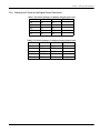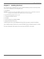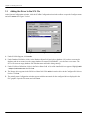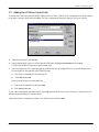
1
GE
Measurement & Control
Validation
Netpac™ I/O Driver for THE FIX™
User’s Manual
M4344 Rev. B
April 2013
Netpac™ I/O Driver for THE FIX™
Software Interface for Netpac Modules
User’s Manual
M4344 Rev. B
April 2013
http://www.ge-mcs.com/en/validation-and-environmental-monitoring.html
©2013 General Electric Company. All rights reserved.
Technical content subject to change without notice.
[no content intended for this page]
ii
Contents
Chapter 1. Introducing the Netpac I/O Driver
1.1
1.2
1.3
1.4
1.5
Supported Netpac Hardware. . . . . . . . . . . . . . . . . . . . . . . . . . . . . . . . . . . . . . . . . . . . . . . . . . . . . . . . . . . . . . . . . . . . . . . . . . . . 1
Supported Intellution Software . . . . . . . . . . . . . . . . . . . . . . . . . . . . . . . . . . . . . . . . . . . . . . . . . . . . . . . . . . . . . . . . . . . . . . . . . . 2
Communications Interface. . . . . . . . . . . . . . . . . . . . . . . . . . . . . . . . . . . . . . . . . . . . . . . . . . . . . . . . . . . . . . . . . . . . . . . . . . . . . . 2
What the Driver Does . . . . . . . . . . . . . . . . . . . . . . . . . . . . . . . . . . . . . . . . . . . . . . . . . . . . . . . . . . . . . . . . . . . . . . . . . . . . . . . . . . . 2
How the Driver Works . . . . . . . . . . . . . . . . . . . . . . . . . . . . . . . . . . . . . . . . . . . . . . . . . . . . . . . . . . . . . . . . . . . . . . . . . . . . . . . . . . 3
Chapter 2. Setting up the Hardware
2.1
2.2
2.3
2.4
2.5
Setting up the Computer. . . . . . . . . . . . . . . . . . . . . . . . . . . . . . . . . . . . . . . . . . . . . . . . . . . . . . . . . . . . . . . . . . . . . . . . . . . . . . . . 5
Checking the Ports on the Windows NT and 95 Platform. . . . . . . . . . . . . . . . . . . . . . . . . . . . . . . . . . . . . . . . . . . . . . . . . . 5
Cabling . . . . . . . . . . . . . . . . . . . . . . . . . . . . . . . . . . . . . . . . . . . . . . . . . . . . . . . . . . . . . . . . . . . . . . . . . . . . . . . . . . . . . . . . . . . . . . . . 6
Setting Control Card Switches and Jumpers . . . . . . . . . . . . . . . . . . . . . . . . . . . . . . . . . . . . . . . . . . . . . . . . . . . . . . . . . . . . . 7
2.4.1 Setting the Analog Control Cards and I/O Cards. . . . . . . . . . . . . . . . . . . . . . . . . . . . . . . . . . . . . . . . . . . . . . . . . . . . . 7
2.4.2 Setting DIP Switch S1 . . . . . . . . . . . . . . . . . . . . . . . . . . . . . . . . . . . . . . . . . . . . . . . . . . . . . . . . . . . . . . . . . . . . . . . . . . . . . . 7
2.4.3 Module Address . . . . . . . . . . . . . . . . . . . . . . . . . . . . . . . . . . . . . . . . . . . . . . . . . . . . . . . . . . . . . . . . . . . . . . . . . . . . . . . . . . . 8
2.4.4 Setting the Baud Rate Jumper . . . . . . . . . . . . . . . . . . . . . . . . . . . . . . . . . . . . . . . . . . . . . . . . . . . . . . . . . . . . . . . . . . . . . 9
2.4.5 Setting the Default Resolution Jumper. . . . . . . . . . . . . . . . . . . . . . . . . . . . . . . . . . . . . . . . . . . . . . . . . . . . . . . . . . . . . . 9
2.4.6 Setting the Operating Voltage. . . . . . . . . . . . . . . . . . . . . . . . . . . . . . . . . . . . . . . . . . . . . . . . . . . . . . . . . . . . . . . . . . . . . . 9
2.4.7 Setting the I/O Cards for the Analog Control Card . . . . . . . . . . . . . . . . . . . . . . . . . . . . . . . . . . . . . . . . . . . . . . . . . . . 9
2.4.8 I/O Address . . . . . . . . . . . . . . . . . . . . . . . . . . . . . . . . . . . . . . . . . . . . . . . . . . . . . . . . . . . . . . . . . . . . . . . . . . . . . . . . . . . . . . . 9
Setting the Digital Control Card and I/O Cards. . . . . . . . . . . . . . . . . . . . . . . . . . . . . . . . . . . . . . . . . . . . . . . . . . . . . . . . . . .10
2.5.1 Setting DIP Switch S1 . . . . . . . . . . . . . . . . . . . . . . . . . . . . . . . . . . . . . . . . . . . . . . . . . . . . . . . . . . . . . . . . . . . . . . . . . . . . .10
2.5.2 Module Address . . . . . . . . . . . . . . . . . . . . . . . . . . . . . . . . . . . . . . . . . . . . . . . . . . . . . . . . . . . . . . . . . . . . . . . . . . . . . . . . . .10
2.5.3 Checksum . . . . . . . . . . . . . . . . . . . . . . . . . . . . . . . . . . . . . . . . . . . . . . . . . . . . . . . . . . . . . . . . . . . . . . . . . . . . . . . . . . . . . . .10
2.5.4 Setting the Baud Rate . . . . . . . . . . . . . . . . . . . . . . . . . . . . . . . . . . . . . . . . . . . . . . . . . . . . . . . . . . . . . . . . . . . . . . . . . . . .10
2.5.5 Setting the Operating Voltage. . . . . . . . . . . . . . . . . . . . . . . . . . . . . . . . . . . . . . . . . . . . . . . . . . . . . . . . . . . . . . . . . . . . .10
2.5.6 Setting the I/O Cards for the Digital Control Card. . . . . . . . . . . . . . . . . . . . . . . . . . . . . . . . . . . . . . . . . . . . . . . . . . .10
2.5.7 Voltage or Current. . . . . . . . . . . . . . . . . . . . . . . . . . . . . . . . . . . . . . . . . . . . . . . . . . . . . . . . . . . . . . . . . . . . . . . . . . . . . . . .12
Chapter 3. Installing the Driver
3.1
3.2
Adding the Driver to the SCU File . . . . . . . . . . . . . . . . . . . . . . . . . . . . . . . . . . . . . . . . . . . . . . . . . . . . . . . . . . . . . . . . . . . . . .14
Adding the I/O Driver Control Task. . . . . . . . . . . . . . . . . . . . . . . . . . . . . . . . . . . . . . . . . . . . . . . . . . . . . . . . . . . . . . . . . . . . . .15
Chapter 4. Adding a Point to Fix and Viewing the Data
4.1
4.2
4.3
4.4
Adding a Data Link to a Picture . . . . . . . . . . . . . . . . . . . . . . . . . . . . . . . . . . . . . . . . . . . . . . . . . . . . . . . . . . . . . . . . . . . . . . . .18
Adding an Analog Input Block to the Database. . . . . . . . . . . . . . . . . . . . . . . . . . . . . . . . . . . . . . . . . . . . . . . . . . . . . . . . . .19
Defining Your Driver Configuration . . . . . . . . . . . . . . . . . . . . . . . . . . . . . . . . . . . . . . . . . . . . . . . . . . . . . . . . . . . . . . . . . . . . .20
Viewing the Results of this Exercise. . . . . . . . . . . . . . . . . . . . . . . . . . . . . . . . . . . . . . . . . . . . . . . . . . . . . . . . . . . . . . . . . . . . .23
Netpac™ I/O Driver for THE FIX™ User’s Manual
iii
Contents
Chapter 5. Configuring the I/O driver
5.1
5.2
5.3
5.4
5.5
GUI I/O Driver Configuration Basics . . . . . . . . . . . . . . . . . . . . . . . . . . . . . . . . . . . . . . . . . . . . . . . . . . . . . . . . . . . . . . . . . . . .25
Channel Setup . . . . . . . . . . . . . . . . . . . . . . . . . . . . . . . . . . . . . . . . . . . . . . . . . . . . . . . . . . . . . . . . . . . . . . . . . . . . . . . . . . . . . . . .28
Device Definition Fields . . . . . . . . . . . . . . . . . . . . . . . . . . . . . . . . . . . . . . . . . . . . . . . . . . . . . . . . . . . . . . . . . . . . . . . . . . . . . . . .29
5.3.1 Moving Between Device Settings. . . . . . . . . . . . . . . . . . . . . . . . . . . . . . . . . . . . . . . . . . . . . . . . . . . . . . . . . . . . . . . . . .30
Input Card Definition Spreadsheet . . . . . . . . . . . . . . . . . . . . . . . . . . . . . . . . . . . . . . . . . . . . . . . . . . . . . . . . . . . . . . . . . . . . .31
5.4.1 Deleting Input Cards . . . . . . . . . . . . . . . . . . . . . . . . . . . . . . . . . . . . . . . . . . . . . . . . . . . . . . . . . . . . . . . . . . . . . . . . . . . . .31
5.4.2 Field Descriptions . . . . . . . . . . . . . . . . . . . . . . . . . . . . . . . . . . . . . . . . . . . . . . . . . . . . . . . . . . . . . . . . . . . . . . . . . . . . . . . .32
Exiting the I/O Driver Configuration Screen . . . . . . . . . . . . . . . . . . . . . . . . . . . . . . . . . . . . . . . . . . . . . . . . . . . . . . . . . . . . .34
Chapter 6. Connecting the Database to the I/O Configuration
6.1
6.2
6.3
6.4
Device Field . . . . . . . . . . . . . . . . . . . . . . . . . . . . . . . . . . . . . . . . . . . . . . . . . . . . . . . . . . . . . . . . . . . . . . . . . . . . . . . . . . . . . . . . . . .35
H/W Options Field . . . . . . . . . . . . . . . . . . . . . . . . . . . . . . . . . . . . . . . . . . . . . . . . . . . . . . . . . . . . . . . . . . . . . . . . . . . . . . . . . . . . .35
I/O Address Field . . . . . . . . . . . . . . . . . . . . . . . . . . . . . . . . . . . . . . . . . . . . . . . . . . . . . . . . . . . . . . . . . . . . . . . . . . . . . . . . . . . . . .35
Signal Conditioning Field. . . . . . . . . . . . . . . . . . . . . . . . . . . . . . . . . . . . . . . . . . . . . . . . . . . . . . . . . . . . . . . . . . . . . . . . . . . . . . .36
Chapter 7. Troubleshooting
7.1
7.2
7.3
Troubleshooting Overview . . . . . . . . . . . . . . . . . . . . . . . . . . . . . . . . . . . . . . . . . . . . . . . . . . . . . . . . . . . . . . . . . . . . . . . . . . . . .39
Using the Mission Control Troubleshooting Program . . . . . . . . . . . . . . . . . . . . . . . . . . . . . . . . . . . . . . . . . . . . . . . . . . . .40
Using the Datascope . . . . . . . . . . . . . . . . . . . . . . . . . . . . . . . . . . . . . . . . . . . . . . . . . . . . . . . . . . . . . . . . . . . . . . . . . . . . . . . . . .43
Appendix A. Generating a Configuration Report
Appendix B. Configuring the Contact Output (TB1)
iv
Netpac™ I/O Driver for THE FIX™ User’s Manual
Chapter 1. Introducing the Netpac I/O Driver
Chapter 1.
Introducing the Netpac I/O Driver
The Netpac (NET) I/O Driver provides the software interface and communications protocol between FIX™ software
and Kaye Instruments Netpac modules. Advanced I/O drivers, such as the NET, take advantage of FIX features and
only work with FIX. This chapter lists the hardware and FIX software that work with this advanced driver.
Intellution’s System Configuration Manual contains information that is common to all FIX drivers. Refer to the System
Configuration Manual for the following information:
•
List of features available with advanced drivers
•
Introduction to driver setup
•
Introduction to driver operation
•
Basic instructions on how to start the configuration program
Use this driver reference manual to find support requirements, configuration values, and error code descriptions that
are specific to this driver. In addition, have your computer, I/O Device, and FIX applications manuals nearby for
reference.
This reference manual also provides an I/O driver tutorial that you might want to use when you set up your I/O Driver.
If you are familiar with Intellution I/O drivers and have some experience with FIX, turn to Chapter 4 for more
information. If you are not familiar with FIX, refer to the System Configuration Manual first.
1.1
Supported Netpac Hardware
A Netpac module is a distributed input/output device that measures, linearizes, and transmits input signals from a
process to a host computer. Netpac modules also output contact and analog values received from a host computer and
can control valves, motors and other equipment.
Netpac modules can be housed in single or multi-module configurations. The single module contains one control card,
either analog or digital, and one input or output card. The multimodule supports one Analog Control card, one Digital
Control card and up to six I/O cards. For example, a multi-module could have a Digital Control card and two digital I/
O cards, and an Analog Control card and four analog I/O cards.
Each control card has specific types of I/O cards with which it can be operated. The number of channels that are
available on each I/O card varies. See Table 1 below for a list of the types of I/O cards and their channels.
Control Card
Analog
Digital
Netpac™ I/O Driver for THE FIX™ User’s Manual
Table 1: I/O Card Types
I/O Card Type
Channels
Volts, DC/TC; High Voltage; RTD 3wire; Contact Output
20
RTD 4-wire
10
Frequency/Period/Status
10
Analog Output
5
1
Chapter 1. Introducing the Netpac I/O Driver
1.2
Supported Intellution Software
The Advanced NET I/O Version 6.xx driver can operate with the following Intellution® software:
•
FIX for Windows NT v6.0 or greater.
•
FIX MMI for Windows NT v6.0 or greater.
•
FIX for Windows 95
•
FIX MMI for Windows 95
1.3
Communications Interface
This I/O Driver requires the following communications interface.
•
Standard computer communications port or
•
Digi International’s DigiBoard
The COM driver uses the serial communications ports standard on most PC’s, COM1 and COM2, and can support up
to sixteen Netpac modules on each port. This driver does not support COM3 and COM4.
Note: The COM ports on the IBM PS/2 Model 50Z are not compatible with THE FIX.
For customers who need multiple ports, the recommended solution is the PC/8e™ serial communications board and
eight-port connector box manufactured by Digi International, Inc. (doing business with DigiBoard), 6400 Flying Cloud
Drive, Eden Prairie, MN 55344. With the PC/8e board, you can configure the COM driver for eight ports, 1-8. The
board manufacturer sells a software diskette containing a device driver and configuration utility. The driver
communicates at either 9600 or 19,200 baud.
A summary of the driver’s maximum capacity is as follows:
Ports
Netpac Modules
I/0 Channels
1.4
8
128, 16 per port
12800
What the Driver Does
The Netpac I/O driver:
•
Programs the Netpac modules with the selections made in the configuration program.
•
Reads user selected analog and digital data from the Netpac modules which continuously scan their I/O channels
through the AutoScan mode, making data available to THE FIX.
•
Writes user-selected data from THE FIX to the Netpac modules.
•
Stores analog data in 32 bit floating point (IEEE) format.
2
Netpac™ I/O Driver for THE FIX™ User’s Manual
Chapter 1. Introducing the Netpac I/O Driver
1.5
How the Driver Works
The Netpac Advanced I/O Driver transfers data between Netpac modules and THE FIX by creating a data table in
memory that it updates with process data as fast as possible. This table is called the poll table or Driver Information
Table (DIT). THE FIX Scan, Alarm and Control (SAC) program fetches data from the Driver Information Table to
refresh the process database and delivers data to the DIT for the driver to write to the Netpac modules.
Each subdivision in the Driver Information Table is called a poll record. A poll record is a block of data read from a
single Netpac module. The poll records are automatically defined when you configure the I/O cards and the I/O
channels through the configuration program in the Netpac driver software.
Chapter 5, Configuring the Driver, explains in detail how you select the data for the Driver Information Table.
Netpac™ I/O Driver for THE FIX™ User’s Manual
3
Chapter 1. Introducing the Netpac I/O Driver
[no content intended for this page]
4
PanaFlow HT Ultrasonic Liquid Flowmeter User’s Manual
Chapter 2. Setting up the Hardware
Chapter 2.
Setting up the Hardware
This chapter discusses hardware configuration issues that affect the operation of the I/O driver software. For complete
information, check your hardware reference documents.
2.1
Setting up the Computer
The FIX Environment Setup Manual covers all the hardware and operating system setup issues that must be addressed
in order to use FIX and the I/O driver. Keep in mind that all FIX SCADA nodes require at least a 486™ CPU when
used with Windows.
2.2
Checking the Ports on the Windows NT and 95 Platform
Connect your cabling to either your PC’s COM1 or COM2 ports or the DigiBoard™ multi-port interface board. You
can combine these two types of ports to create up to eight channels. Use the documentation provided with your
DigiBoard to install it. When setting up COM ports, check the following:
•
The DigiBoard can provide all eight channels, and be used as serial ports COM3 through COM10. After
installation, bear in mind the following:
You can reassign the port numbers for each of the DigiBoard ports. Otherwise, the software automatically numbers
the ports starting where the resident ports left off. If your computer only has one COM port, the DigiBoard will use
COM2 - COM10; if your computer has COM 1 and COM 2, the DigiBoard will use COM3 - COM10. Refer to the
DigiBoard configuration help option for more information on remapping the ports.
Most DigiBoard device drivers do not use interrupts. Refer to your DigiBoard documentation to see if your specific
DigiBoard driver requires interrupt settings on the hardware.
•
The Driver I/O Configurator program allows a total of 8 ports, each used only once as a channel’s primary port.
•
The PC’s COM port hardware must enable serial interrupts.
2.2
Checking the Ports on the Windows NT and 95 Platform (cont.)
•
No expansion board in the PC can use the same interrupt levels as COM port 1 or port 2. In most PCs, COM Port 1
uses IRQ4 and COM Port 2 uses IRQ3. If a conflict occurs, change the interrupt level of the conflicting expansion
boards.
•
When using a Windows driver, your COM ports needs 16-byte first-in-first-out (FIFO) support. Without FIFO
support, you may experience communications failure.
Netpac™ I/O Driver for THE FIX™ User’s Manual
5
Chapter 2. Setting up the Hardware
2.3
Cabling
Netpac modules require a shielded, single twisted pair of wires to communicate to the host computer. The Netpac
modules have an RS-485 interface and the PC communications port has an RS-232 interface. For the two to
communicate, an RS-232 to RS-422/485 interface converter must be installed at each port.
To connect more than one Netpac module, connect the RS-232 cable from each PC port to an RS- 232 to RS-485
converter box and then connect up to sixteen Netpac modules. See Figure 1 below.
Kaye provides two 120S termination resistors. Connect one across the terminals marked RD(A) and RD(B), and the
other across the terminals marked 422- and 422+ on the last Netpac module. There are also two jumpers inside the
converter that need to be set as follows:
•
Jumper JP1 - SD selected
•
Jumper JP2 - Echo off
Figure 1: Cabling Netpac Modules
6
Netpac™ I/O Driver for THE FIX™ User’s Manual
Chapter 2. Setting up the Hardware
2.4
Setting Control Card Switches and Jumpers
Both the Analog and the Digital Control cards have DIP switches for setting the module address and jumpers for
selecting the baud rate. The Analog Control card also has a jumper to select the default data resolution (high, medium
or low). You use the information from these settings when you configure the driver in Chapter 5.
The settings described here are for the purpose of configuring the Netpac modules to operate with the driver software.
For more detailed information on installing single- and multi-module Netpacs, and wiring the inputs and outputs, refer
to the Netpac User’s Guide. After you complete the Netpac driver configuration, a report can be produced to show what
control card has been configured at each Module Address, the types of cards and the applicable DIP switch and jumper
settings. Refer to Appendix A, Generating a Configuration Report.
2.4.1 Setting the Analog Control Cards and I/O Cards
The Analog Control card converts analog signals from thermocouples, RTD's, voltage input sensors and current to a
digital representation and transmits the signal values to THE FIX. It also processes commands from THE FIX to open
or close contacts on a contact output card, the local contact output on the Analog Control card (TB1). See Appendix B
for further information on TB1.
2.4.2 Setting DIP Switch S1
At DIP switch S1, you set the following features using slides 1 to 8:
Table 2: DIP Switch S1 Settings
Feature
Slide
Netpac Module Address
1 to 4
AutoScan/Calibrate
5
CPU or measurement failure mode for the watchdog timer
6
Reset contact outputs
7
Checksum
8
Netpac™ I/O Driver for THE FIX™ User’s Manual
7
Chapter 2. Setting up the Hardware
2.4.3 Module Address
Refer to Table 3 below to set a unique address (00-15) for each Netpac module on the port.
Table 3: Setting the Module Address for the Analog Control Card
Module
Address
Slide 1
Slide 2
Slide 3
Slide 4
00
ON
ON
ON
ON
01
OFF
ON
ON
ON
02
ON
OFF
ON
ON
03
OFF
OFF
ON
ON
04
ON
ON
OFF
ON
05
OFF
ON
OFF
ON
06
ON
OFF
OFF
ON
07
OFF
OFF
OFF
ON
08
ON
ON
ON
OFF
09
OFF
ON
ON
OFF
10
ON
OFF
ON
OFF
11
OFF
OFF
ON
OFF
12
ON
ON
OFF
OFF
13
OFF
ON
OFF
OFF
14
ON
OFF
OFF
OFF
15
OFF
OFF
OFF
OFF
Slides 5 to 8 on DIP switch S1 are described briefly here. Refer to Section 2-1 in the Netpac User's Guide for detailed
information.
•
Slide 5 AutoScan/Calibrate: Slide 5 must be OFF. In the OFF position, the Netpac module scans all channels and
performs a calibration every 25 seconds.
•
Slide 6 Watchdog timer relay: Slide 6 controls the failure mode when CPU or measurement failure occurs. Set
slide 6 ON to enable the CPU failure mode, or set it OFF to enable measurement failure mode. CPU failure mode
monitors on board processor malfunctions. Measurement failure mode checks that the Netpac module is actually
processing measurements. Select the mode that fits your application. GE recommends slide 6 be set in the ON
position.
•
Slide 7 Contact Output Reset: Slide 7 specifies the state of the contact outputs on the contact output card and the
local contact output (TB1) on the Analog Control card at powerup. When slide 7 is set to OFF, all contact outputs
are reset to their normal position when you apply primary power. Select the mode that fits your application. When
slide 7 is set ON, there is no change to the contact outputs when primary power is applied.
•
Slide 8 Checksum: Slide 8 must be OFF for the module to communicate with THE FIX.
8
Netpac™ I/O Driver for THE FIX™ User’s Manual
Chapter 2. Setting up the Hardware
2.4.4 Setting the Baud Rate Jumper
The baud rate jumper, P14, is located near the right center of the control card. Install the jumper to select either 9600 or
19,200 baud. All Netpac modules on a port must have the same baud rate.
2.4.5 Setting the Default Resolution Jumper
The resolution jumper, P16, is located above the baud rate jumper. It sets the default resolution for all input channels
associated with this control card. Set the jumper at one of the following resolutions listed in Table 2-3.
Higher resolutions require more processing time for greater accuracy and yield fewer samples per interval time.
When you configure a channel, you can accept the default setting, or override the default on a per input channel basis.
See the Resolution section in Chapter 5, Configuring the Driver.
Jumper Setting
Table 4: Jumper Settings
Bits Plus Sign
Default Resolution
2 line cycles
14
High
1 line cycle
13
Medium
1/4 line cycle
11
Low
2.4.6 Setting the Operating Voltage
If your power source is +12VDC, install the power selection jumper on the +12V side of P5. If your power source is
+24 VDC, install the power selection jumper on the +24V side of P5.
2.4.7 Setting the I/O Cards for the Analog Control Card
The I/O cards associated with the Analog Control card do not require any jumper or switch settings.
If you have current inputs, install a 25-ohm, 0.05 percent resistor across the appropriate channel. See “Current
Transmitter Connections” in Section 2 of the Netpac User's Guide.
2.4.8 I/O Address
In a single module Netpac with an Analog Control card, the I/O card is always card number 0. In a multi-module
Netpac, determine the Analog I/O card number (0-4) by its position in relation to the control card.
Netpac™ I/O Driver for THE FIX™ User’s Manual
9
Chapter 2. Setting up the Hardware
2.5
Setting the Digital Control Card and I/O Cards
A Digital Control card supports up to five digital input/analog output cards.
2.5.1 Setting DIP Switch S1
The eight position DIP switch S1, located on the Digital Control card, sets the module address and controls the
checksum.
2.5.2 Module Address
Set the module address (00-15) on DIP switch S1 at slides 1 to 4. Refer to Table 3 on page 8. Slides 5 and 6 must be set
to On. Slide 7 is not used.
2.5.3 Checksum
Set slide 8 to OFF for the module to communicate with THE FIX.
2.5.4 Setting the Baud Rate
The baud rate jumper, JU5, is located near the center of the Digital Control card. Install the baud jumper at: position A
for 19,200, B for 9600.
2.5.5 Setting the Operating Voltage
See “Setting the Operating Voltage” on page 9..
2.5.6 Setting the I/O Cards for the Digital Control Card
There are two types of I/O cards associated with the Digital Control card: the Frequency/Period/Status card and the
Analog Output card.
The Frequency/Period/Status card has “Pulse Counter” silk screened on it. Switch S1 has eight slides. Slide 8 is not
used. Refer to the following tables for switch settings.
Slide 1
ON
OFF
1 Hz
0 - 65535 Hz
OFF
ON
0.1 Hz
0 - 6553.5 Hz
ON
ON
0.01 Hz
0 - 655.35 Hz
Slide 3
10
Table 5: DIP Switch Settings: Frequency
Slide 2
Resolution
Netpac Range
Table 6: DIP Switch Settings: Period
Slide 4
Period
Netpac Range
ON
ON
1 ms
0- 65535 Hz
OFF
ON
0.1 ms
0 - 6553.5 Hz
ON
OFF
0.01 ms
0 - 655.35 Hz
OFF
OFF
0.001 ms
0 - 65.535 ms
Netpac™ I/O Driver for THE FIX™ User’s Manual
Chapter 2. Setting up the Hardware
2.5.6 Setting the I/O Cards for the Digital Control Card (cont.)
Table 7: DIP Switch Settings: I/O Address (Digital Input Card)
Slide 5
Slide 6
Slide 7
I/O Address
ON
ON
ON
0
OFF
ON
ON
1
ON
OFF
ON
2
OFF
OFF
OFF
3
ON
ON
OFF
4
Table 8: DIP Switch Settings: I/O Address (Analog Output Card)
Slide 1
Slide 2
Slide 3
I/O Address
OPEN
OPEN
OPEN
0
CLOSE
OPEN
OPEN
1
OPEN
CLOSE
OPEN
2
CLOSE
CLOSE
OPEN
3
OPEN
OPEN
CLOSE
4
Netpac™ I/O Driver for THE FIX™ User’s Manual
11
Chapter 2. Setting up the Hardware
2.5.7 Voltage or Current
Set the output ranges for each channel with jumpers JN1 to JN5: 0-5 volts, 0-10V, 1-5mA and 4-20 mA. See Figure 2
below for the Analog Output jumper positions.
Figure 2: Analog Output Card Jumper
for Setting Voltage and Current
12
Netpac™ I/O Driver for THE FIX™ User’s Manual
Chapter 3. Installing the Driver
Chapter 3.
Installing the Driver
These instructions apply to installing the driver as part of THE FIX installation procedure, the most likely situation.
You can, however, add the driver to an existing FIX system.
1. Start Windows.
IMPORTANT: If you have been running other Windows applications, make sure they are closed before you proceed,
including the Microsoft Office Shortcut Bar and your screen saver program.
2. Insert THE FIX Setup diskette in drive A or B.
3. Click Start on the Windows task bar.
4. Select Run.
5. In the Run dialog box, type a:setup or b:setup.
6. Follow the instructions on the screen.
At THE FIX Options list box, check I/O Drivers and click OK. Follow the prompts to complete the installation.
At the “Installation complete. Would you like to start the FIX DMACS System Configuration program?”, click Yes.
The System Configuration window appears with your node name and THE FIX version number.
Netpac™ I/O Driver for THE FIX™ User’s Manual
13
Chapter 3. Installing the Driver
3.1
Adding the Driver to the SCU File
At the System Configuration window, click the SCADA Configuration icon in the toolbox or open the Configure menu
and select SCADA. See Figure 3 below.
Figure 3: SCADA Configuration Dialog Box
1. Under SCADA Support, click Enable.
2. Under Database Definition, click ? in the Database Name field, and select a database. (If you have not created a
database and do not want to use the empty database file named “DATABASE”, you can enter a new name. The
SCU will create an empty database file with that name and load it during startup.)
3. Under I/O Driver Definition, click ? in the Driver Name field. A list of the installed drivers appears. Highlight NET
- Netpac I/O Driver Rev 6.xx and click OK.
4. The Netpac driver appears in the I/O Driver Name field. Click Add to insert the driver in the Configured I/O drivers
list box. Click OK.
5. The main System Configuration window appears with the mnemonic for the configured drivers displayed in the
PLC graphic. Open the File menu and select Save.
14
Netpac™ I/O Driver for THE FIX™ User’s Manual
Chapter 3. Installing the Driver
3.2
Adding the I/O Driver Control Task
To add the I/O Control program (IOCNTRL.EXE) to the list of tasks, click the Task Configuration icon in the toolbox
or open the Configure menu and select Tasks. The Task Configuration dialog box appears. See Figure 4 below.
Figure 4: Task Configuration Dialog Box
1.
Under Start Up mode, click Normal.
2. In the Filename field, click ? for a list of installed FIX tasks. Highlight IOCNTRL.EXE and click Open.
C:\FIX32\IOCNTRL.EXE appears in the Filename field.
3. You can configure the I/O Control program to automatically start all configured drivers or just the Netpac driver.
To start all drivers automatically when THE FIX starts:
a. Click in the Command Line filed and type /a
b.
Click Add and then OK.
To start just the Netpac driver automatically:
a. Click in the Command Line and type /SNET
b. Click Add and then OK.
To exit without configuring automatic startup, click Add and then OK. You can use the I/O Driver Control icon in the
Windows Program manager to start the drivers.
At the main System Configuration window, open the File menu and select Save.
Netpac™ I/O Driver for THE FIX™ User’s Manual
15
Chapter 3. Installing the Driver
[no content intended for this page]
16
Netpac™ I/O Driver for THE FIX™ User’s Manual
Chapter 4. Adding a Point to Fix and Viewing the Data
Chapter 4.
Adding a Point to Fix and Viewing the Data
To configure your I/O communication, there are several easy steps you need to follow. This section provides an
exercise that walks you through the setup of your driver, providing you with possible entries you can make in your
configuration, and demonstrates how to get real I/O displayed in a picture. Keep in mind that you can repeat this
exercise to help guide you through the configuration of your driver, database blocks, and displays.
The focus of this exercise is to provide enough information so you can create:
•
Pictures to graphically display and control data in your hardware.
•
Blocks in the database that monitor locations in your hardware.
•
A driver configuration that receives data from your hardware.
The Tutorial that comes with your FIX software teaches you how to build database blocks, create pictures, and use
Dynamos. Unlike the Tutorial, which uses the simulation (SIM) driver, the exercise that you’ll go through in this
section not only has you add a link to a picture and add a database block, but also steps you through the setup of the
NET I/O driver.
This exercise is designed to run on a SCADA node that has the NET I/O Driver installed. If you have not installed your
I/O Driver, please do so now. Install your I/O Driver using the FIX installation disk. This exercise also requires the
default NET configuration file that was shipped with your I/O Driver software.
All steps for this exercise were designed for the Windows platform.
Netpac™ I/O Driver for THE FIX™ User’s Manual
17
Chapter 4. Adding a Point to Fix and Viewing the Data
4.1
Adding a Data Link to a Picture
This step in the exercise has you:
•
•
•
Start your FIX software.
Load the Draw application.
Add a Data Link to a picture.
1. Start the FIX software by double-clicking the Startup icon,
software.
2.
Double-click the Draw Icon,
from the FIX group. This loads your FIX
to load the Draw program and open a new picture.
3. Select the Data Link button,
from the toolbox (or select Link... from the tool menu then select the Data Link
button) and a stamper cursor appears on the screen. Position the stamper cursor where you want the link to appear
and click the left mouse button once. The Data Link dialog box appears, as shown in Figure 5 below.
Figure 5: Data Link Dialog Box
Continue with the next step in this exercise to add the block that this link accesses for information.
18
Netpac™ I/O Driver for THE FIX™ User’s Manual
Chapter 4. Adding a Point to Fix and Viewing the Data
4.2
Adding an Analog Input Block to the Database
This step in the exercise has you:
•
Identify the block that the Data Link will use to get data.
•
Add an Analog Input block to the database.
•
Configure the block’s driver fields.
1.
Enter AI1 in the Data Link dialog box Tagname field and select the OK button. Your FIX software then asks if you
want to add the block.
2. Select the Add button. The Select a Type dialog box appears so you can select the type of database block you want
to add to the database.
3. Select the Analog Input (AI) block and click OK. The Analog Input (AI) dialog box appears.
Figure 6: Analog Input Block Dialog Box
4.
Complete this dialog box by entering NET in the Device field and D11:0:0 in the I/O Address field where D11 is the
device name, the first zero is the I/O card number, and the second zero is the channel number. This address
configuration can be found in the I/O configurator. Click OK to save this configuration and exit this dialog box.
5.
A dialog box with the I/O address may appear indicating that the address is not in the configuration. Click Yes to
add the address to the I/O Driver Configurator.
6. This dialog box will not appear if the address is already in the driver configuration. This is probably the case, since
the input card D11:0:0 is included in the default driver configuration shipped with your I/O Driver.
Continue with the next step in this exercise to define your I/O driver so the block can retrieve data from your hardware.
Netpac™ I/O Driver for THE FIX™ User’s Manual
19
Chapter 4. Adding a Point to Fix and Viewing the Data
4.3
Defining Your Driver Configuration
This step in the exercise has you:
•
Specify the communication parameters
•
Specify the module address
•
Specify the type of control card
•
Specify the input cards
•
Save and reload the driver configuration.
•
Place the AI1 block on scan.
1. With the I/O Driver Configurator dialog box (Figure 5-1) on your screen, select the Setup button,
to
display the Channel Communication Setting dialog box, as shown in Figure 7 below. Enter the communication
parameters, and click OK. (Refer to Section 5.2 for more information on the communication parameters.)
Figure 7: Channel Communication Settings Dialog Box
20
Netpac™ I/O Driver for THE FIX™ User’s Manual
Chapter 4. Adding a Point to Fix and Viewing the Data
4.3
Defining Your Driver Configuration (cont.)
2. At the NET Driver Configurator dialog box, enter the name and module address of the Netpac device, as shown in
Figure 8 below. The description field is optional. Select the control card type and temperature units.
Figure 8: Driver Configuration Screen
3. To program the individual channels on the card, double click in the I/O Card Number column to select the first
input card. The Input Card Edit dialog box appears, as shown in Figure 9 below.
Figure 9: Input Card Edit Dialog Box
Netpac™ I/O Driver for THE FIX™ User’s Manual
21
Chapter 4. Adding a Point to Fix and Viewing the Data
4.3
Defining Your Driver Configuration (cont.)
4. Select the I/O card number and type. Leave the default values in the Poll Time and Access Time fields. These
parameters are discussed in detail in section 5.4.2. To program one or more channels, click the checkbox to the left
of the channel number. Then select the function type and resolution, and click Set. All channels with the checkbox
enabled will be programmed with the same function type and resolution. If you want to program other channels
with a different function type, deselect the channels you have already programmed before you select a new
function type.
5. Click OK.
6. Click the Exit icon,
at the top of the I/O Driver Configurator dialog box and the FIX software prompts you
to select your exit options, as shown in Figure 10 below.
Figure 10: I/O Configurator - Exit Options
7. Check the Save I/O Driver Configuration and Reload I/O Driver Configuration options and click OK.
8. The I/O Driver Reload dialog box appears asking if you want to continue. Select Yes, and the FIX software reloads
the driver configuration. The FIX software indicates that the reload is successful by displaying the Reload
Successful dialog box. When this appears, click OK to continue.
22
Netpac™ I/O Driver for THE FIX™ User’s Manual
Chapter 4. Adding a Point to Fix and Viewing the Data
4.4
Viewing the Results of this Exercise
This step in the exercise has you:
•
Switch to the View application using the new QuickView function.
•
View your Data Link updating with process data coming from your I/O driver.
1. Your FIX software returns you to the Draw application. The Data Link appears as a series of pound (#) symbols,
such as ########. This represents the location of the link while in the drawing mode.
Click the QuickView icon,
to switch from Draw to the View application. Switching to View allows you to see the
link updating with Netpac data.
You should see your link updating with real-time data.
If you see question marks, such as ????????, this indicates that your driver is having problems communicating to the
hardware. Please refer to your troubleshooting guide in Chapter 7 of this driver reference manual for instructions on
how to troubleshoot this problem.
2. To return to the Draw application, select QuickDraw from the View pull-down menu or type <Ctrl><Q>.
Netpac™ I/O Driver for THE FIX™ User’s Manual
23
Chapter 4. Adding a Point to Fix and Viewing the Data
[no content intended for this page]
24
Netpac™ I/O Driver for THE FIX™ User’s Manual
Chapter 5. Configuring the I/O driver
Chapter 5.
Configuring the I/O driver
This chapter describes how to configure your I/O driver using a graphical user interface (GUI) program called the I/O
Driver Configurator. The I/O driver configuration consists of a map of channels, devices, and input card records. It also
contains several user-defined communication parameters.
See Chapter 6, Configuring I/O Drivers, in the System Configuration Manual for information about the following:
•
Understanding I/O Driver Setup.
•
Starting the configuration program.
To learn about the configuration program’s conventions for entering and manipulating data, refer to the Basics Manual
in Intellution’s System Setup book.
The following subsections tell you what information you must enter into the I/O Driver Configurator program’s fields
to work with the NET driver.
5.1
GUI I/O Driver Configuration Basics
After starting the I/O Driver Configuration program for an advanced GUI I/O driver, the initial screen, shown in
Figure 11 below, appears.
Figure 11: I/O Driver Configuration Screen
Netpac™ I/O Driver for THE FIX™ User’s Manual
25
Chapter 5. Configuring the I/O driver
5.1
GUI I/O Driver Configuration Basics (cont.)
The . . .
Table 9: Driver Configuration Sections
Lets You . . .
Menu Bar
Access file management, display alarm option, custom display, and on-line help
commands.
Tool Bar
Access some of the menu commands with a single mouse click. Commands include
Open, Save, Reload, Exit, and Help. Clicking these Tool Bar buttons invokes the same
dialog boxes as the menu commands.
Channel Selection
Select a channel. Clicking the Setup button provides the Port Settings dialog box, from
which you can set your channel’s communications parameters.
Netpac Settings
Set up individual devices.
Input Card Spreadsheet
Display configured input cards. Click any record to set the I/O address for specific input
cards.
Status Bar
Display the status of the <Caps Lock>, <Num Lock> and <Scroll Lock> keys as well as
a description of the selected menu command.
To enter data into the driver configuration worksheet, select commands from the menus on the menu bar, as shown in
Figure 5-1. Below is a summary of each available menu:
File menu — provides standard file commands, such as New, Open, Close, Save and Save As. The Open, Save, and Save
As commands allow you to select a File Type option. Use this option to select either the extension for your driver
configuration files or the .CSV extension for ASCII report files.
The Reload command updates the current configuration with the one in memory. This is necessary for the rest of the
system, such as Database Builder, to be able to see the new information. This will temporarily stop SAC and the Driver,
load the new driver configuration, and restart SAC and the Driver.
The File menu also lists the four most recent driver configuration files you have opened. Selecting one of these files
lets you open it without using the Open command.
The Exit command will allow you to close the I/O Driver configuration program.
View menu — provides toolbar and status bar display commands.
Options Menu — provides access to the Display Alarms command. This command allows you to control the
distribution of driver alarms to the alarm destinations enabled in the SCU, except the Alarm Summary Display. By
default, display of alarms is ENABLED. The Alarm Summary Display shows communication errors as database block
alarms, not driver alarms.
Help menu — provides access to Intellution’s on-line help system for the I/O Driver Configuration program.
The I/O Driver Configuration program lets you open one driver configuration file at a time. Each configuration file
contains multiple input cards with limits based on available memory.
26
Netpac™ I/O Driver for THE FIX™ User’s Manual
Chapter 5. Configuring the I/O driver
5.1
GUI I/O Driver Configuration Basics (cont.)
The settings you make with the I/O Driver Configuration program must correspond to the settings in the process
control hardware so that FIX can communicate with your hardware.
After starting the I/O Driver Configuration program, you are ready to begin configuring your I/O driver. You can
configure your I/O driver by either entering text into the fields provided or by opening an existing driver configuration
and modifying its settings.
To create a new driver configuration, do the following:
1. Start the I/O Driver Configuration program. See Section 6.2 of the System Configuration Manual for instructions.
2. Select New from the File menu.
3. Enter your Channel, Device, and Input Card settings into the fields provided. Refer to the following sections of this
manual for descriptions of these fields.
4.
Save your file. The default filename is NODENAME.NET.
Note: You can save using any FILENAME.NET; but the driver will only load the NODENAME.NET file.
To load a different configuration, do the following:
1. Select Open from the File menu or click the open icon on the tool bar.
2. Select the desired file.
3. Save as NODENAME.NET
4. Select Yes when prompted to replace NODENAME.NET.
5. Reload the configuration.
Netpac™ I/O Driver for THE FIX™ User’s Manual
27
Chapter 5. Configuring the I/O driver
5.2
Channel Setup
A channel is a logical connection between an I/O driver and Netpac. There are eight channels available, as shown in
Figure 11 on page 25. Each channel’s Port Settings dialog box appears when you click the channel number button, then
click the Setup button. These dialog boxes allow you to assign physical ports and communication parameters to each
channel.
Click Setup to display the Primary Port Settings dialog box, as shown below in Figure 12 below.
Figure 12: Port Settings Dialog Box
Port — defines the physical COM port you want the channel to communicate through. Generally, use COM1 and
COM2 for PC ports. Choose any port number from COM3 to COM10 for the DigiBoard™. A total of eight ports can
be used. If you do not want to use the primary port (or you want to temporarily disable it), select None in the Port
selection field. Note that the default is None; a port must be selected for the driver to communicate.
Baud Rate — identifies the speed at which the Netpac and software will communicate. This value must match the
value used by the Netpac that this channel is communicating with in order to establish communication. The following
baud rates are supported for this I/O driver:
•
9800
•
19200
Reply Timeout — specifies the number of seconds allowed for Netpac to reply to a request to read or write data. If the
reply timeout expires, the driver sends a retry message. The reply timeout ranges from 0.1 to 1800.0 seconds. If the
response time from the Netpac is slow due to processing overhead, you may need to increase the timeout value. The
default reply timeout is 1.0 seconds.
Retries — specifies the number of times that the driver re-sends a failed message before marking all input card as
failed and initiating the Delay Time. The Retries range from 0 to 9. If you specify zero, the driver sends no retries. Note
that this parameter applies only to messages sent by the NET I/O driver. The default value is 3 retries.
Delay — indicates the amount of time, in seconds, to place an input card off-line after a communications failure. After
the delay time expires, the driver attempts to re-initiates the communication cycle (only the primary port is configured).
The delay ranges from 0.0 to 3600.0 seconds. The default delay time is 10.0 seconds.
28
Netpac™ I/O Driver for THE FIX™ User’s Manual
Chapter 5. Configuring the I/O driver
5.3
Device Definition Fields
A device is any field device or system that an I/O driver communicates with. The Device Definition fields are shown in
Figure 13 below.
Figure 13: Driver Configuration Screen
Netpac™ I/O Driver for THE FIX™ User’s Manual
29
Chapter 5. Configuring the I/O driver
5.3.1 Moving Between Device Settings
The driver can communicate with up to 128 different Netpac modules, eight ports with up to 16 Netpac modules on
each port. From the Add Device box, use the <Page Up>, <Page Down>, <Arrow> keys, or scroll bar to select and
highlight the desired device. That device’s settings appear in the appropriate fields. The device definition fields are
described below:
Add — creates a device.
Delete — deletes the device that is currently selected. It will also remove all input cards defined for this device.
Device Name — assigns a name to a particular Netpac module. This name is used by the driver to access I/O points on
the device and must be a unique name not used by any other device accessed by the driver on any channel. You can
enter up to five alphanumeric characters.
Description — assigns a description to a device. This parameter is optional. You can enter up to forty characters.
Module Address — specifies the module address of the control card that this device’s input cards access. Valid module
addresses are:
•
0 - 15
Control Card Type — specifies the control card type that this devices input cards access. Valid control card types are:
•
Analog
•
Digital
Temperature Units — specifies the temperature units to be used for the selected control card. This field only applies
to analog control cards. Valid entries are:
•
Celsius
•
Fahrenheit
30
Netpac™ I/O Driver for THE FIX™ User’s Manual
Chapter 5. Configuring the I/O driver
5.4
Input Card Definition Spreadsheet
An input card record is a set of I/O points that are read periodically as a group. I/O points are normally written
individually upon request. The input card spreadsheet, displayed at the bottom of the I/O Driver Configuration screen,
shows the input cards configured for the selected channel and device.
To scroll through the input card spreadsheet and view different input cards, use the scroll bar or the <Page Up> and
<Page Down> keys.
You input data into the input card spreadsheet by clicking any field within the spreadsheet. The Input Card Edit dialog
box for the selected record appears. Enter all your input card values in the Input Card Edit dialog box and click OK. The
Input Card Edit dialog box is shown in Figure 14 below.
Figure 14: Input Card Edit Fields
5.4.1 Deleting Input Cards
To delete an input card, set the I/O Card Number to NONE. The record does not appear in the spreadsheet when you go
back to the device and spreadsheet level.
Netpac™ I/O Driver for THE FIX™ User’s Manual
31
Chapter 5. Configuring the I/O driver
5.4.2 Field Descriptions
When available, click the down arrow to select values from the drop-down lists. Type in the desired value for all other
fields. The input card definition fields are described below.
I/O Card
Number — specifies the number of the I/O card which will be polled by this input card. A selection of None will delete
the input card. Valid entries are:
•
0-4
•
None
Type — specifies the type of I/O card (module) that will be accessed by this input card. The choices available will
depend on the control card type for the current module. Refer to Table 10 below for valid entries.
Table 10: Valid Control Type Entries
Control Card Type
I/O Card Type
Analog
VO - Volts, DC/TC I/O Card
HV - High Voltage I/O Card
R3 - RTD 3-Wire I/O Card
R4 - RTD 4 - Wire I/O Card
CO - Contact Output I/O Card
Digital
FP - Frequency/Period/Status I/O Card
AO - Analog Output I/O Card
Block Configuration
Poll Time — specifies how frequently (in seconds) the polling task reads data for this input card. The poll time ranges
from 0.0 to 86400.0 seconds (a maximum of 24 hours), or disabled.
An entry of 0 tells the driver to poll as fast as possible.
Do not confuse the poll time with the scan time you enter for individual database blocks. The poll time defines how
often the polling task refreshes the Driver Image Table from the hardware. Scan time defines how often SAC retrieves
data on a point-by-point basis from the driver image table. For most applications, the blocks scan time should be less
frequent than (greater time interval) or equal to the poll time.
Note: To disable the Poll Time, enter a dash (-) or D character in the poll time field. This feature is useful for input
cards that are used strictly for output.
Access Time — specifies how long the I/O driver continues to update input cards when there is no read/write activity
on those records. The access time ranges from 0.0 to 172800.0 seconds (a maximum of 48 hours) or disabled.
Note:
32
If the access time is set to disabled for poll blocks that are time-based, the driver will\ continue to poll for
information even if there is no activity.
Netpac™ I/O Driver for THE FIX™ User’s Manual
Chapter 5. Configuring the I/O driver
5.4.2 Field Descriptions (cont.)
Freq/Per/Stat Configuration
Frequency — specifies the frequency configured for the current I/O card. This field only applies to Frequency/Period/
Status I/O cards. Valid entries are:
•
1 Hz
•
0.1 Hz
•
0.01 Hz
Period — specifies the period configured for the current I/O card. This field only applies to the Frequency/Period/
Status I/O cards. Valid entries are:
•
1 ms
•
0.1 ms
•
0.01 ms
•
0.001 ms
.
Table 11: Input Card Examples
I/O Card Type
Frequency
Period
I/O Card #
2
VO - Volts, DC/TC
N/A
1
FP - Frequency/Period/Status 1 Hz
Function
Resolution
N/A
T T/C
HIGH
0.01ms
Frequency
LOW
Channels
Function — specifies the function to apply to one or more channels in the current input card. Valid functions depend
on the type of I/O card. See table 5-4 for valid entries in this field.
Table 12: Valid Functions
Valid Functions
I/O Card Type
Volts, DC/TC
Skip, 55mV, 100mV, 1V, 100V, J T/C, K T/C, T T/C, E T/C, S T/C, R T/C, B T/C, 10-50
mA, 4-20 mA, 0-1 mA, Con/In
High Voltage
Skip, 0-150 V
RTD 3-Wire
Skip, 100Pt/ DIN 100Pt/US, 10 CU
RTD 4-Wire
Skip, 100Pt/ DIN 100Pt/US
Contact Output
Contact Output
Frequency/ Period/Status
Skip, Frequency, Period, Status In
Analog Output
Skip, Analog Output
Netpac™ I/O Driver for THE FIX™ User’s Manual
33
Chapter 5. Configuring the I/O driver
5.4.2 Field Descriptions (cont.)
Resolution — specifies the resolution to apply to one or more channels in the current input card. Once you select the
function, the Resolution menu appears. The four resolution choices are High, Medium, Low and Default. The
resolution you select determines the scan rate of the Netpac module and the accuracy of the data collection. The higher
the resolution, the slower the scan rate and the higher the data accuracy.
Resolution jumper P16 on the Analog Control card sets the integration period for all input channels connected to the
control card. When you installed the Analog Control card, you set the jumper at an integration period of ¼ line cycle, 1
line cycle or 2 line cycles. The jumper setting is the default. (See Chapter 2, Setting Up the Hardware.)
To keep the jumper setting for a channel, select Default. To override the jumper setting, select an alternate resolution
from the menu. Valid entries are:
•
Default
•
High
•
Medium
•
Low
Set — allows the user to set the function and resolution of one or more channels in the current input card. When this
button is clicked, all channels which are checked will be set to the function and resolution listed in the Function and
Resolution list boxes.
5.5
Exiting the I/O Driver Configuration Screen
When you have completed your configuration of the driver, select the Save or Save As commands from the File pulldown menu to save your changes. If FIX is running, SAC can use all input cards as soon as you load the new I/O
configuration.
To reload the new configuration without restarting FIX, click the RELOAD icon, or select the RELOAD command from
the File pull-down menu. A dialog box will appear warning you that SAC and the I/O Driver will be stopped for
RELOAD. Continue by clicking YES or NO. If YES is selected, the new I/O driver configuration will be loaded, and SAC
and the I/O driver will be restarted. If NO is selected, the existing I/O driver configuration will continue to be loaded
and used until the configuration is reloaded or when FIX is restarted.
Select the Exit command from the File pull-down menu to exit the configuration program.
34
Netpac™ I/O Driver for THE FIX™ User’s Manual
Chapter 6. Connecting the Database to the I/O Configuration
Chapter 6.
Connecting the Database to the I/O Configuration
This chapter describes the I/O address fields found in primary blocks; that is, those blocks that communicate to field
devices. This address must correspond to a single I/O point that is part of one of your input cards. The fields are shown
below and are described in the sections that follow:
•
Device field
•
Hardware Options field
•
I/O Address field
•
Signal Conditioning field
6.1
Device Field
The DEVICE field indicates which I/O driver is being used to access the I/O address used by the block. The default entry
is the 3 letter acronym for the driver listed as the first driver in the SCU SCADA Set Up dialog box. The acronym for
the Kaye Netpac is NET. Enter NET in this field.
Note: The use of the name “device” here has nothing to do with the devices defined in the I/O Driver Configurator
program or the DEVICE parameter in the I/O Address field.
6.2
H/W Options Field
The NET I/O Driver has no hardware options. Input in this field is ignored.
6.3
I/O Address Field
The I/O ADDRESS field indicates where the data for the database block is stored and uses the following format for
analog and digital addresses.
DEVICE:CARD_NUMBER:CHANNEL
For examples of valid I/O addresses, please refer to Table 13 on page 36.
Block I/O Address fields accepts a maximum of 128 characters. The parts of the format are discussed below:
Device — indicates the name you assigned in the DEVICE NAME field of the Device Definition in the I/O driver
configuration program. It is simply an alphanumeric tag that the Database Builder uses to differentiate input cards
collected from different field devices.
Card_Number — specifies the number of the I/O Card that was assigned in the I/O driver configurator.
Channel — specifies a channel number on the I/O card that was previously defined. This should be a channel that has
a function specified for it in the I/O driver configurator.
Note: Netpac modules are numbered 0 -15. Cards are numbered 0-4; channels are numbered 0-4, 0-9, or 0-19,
depending on the specific card type.
Netpac™ I/O Driver for THE FIX™ User’s Manual
35
Chapter 6. Connecting the Database to the I/O Configuration
6.3
I/O Address Field (cont.)
The Database Builder checks the I/O address you enter in the block with the I/O configuration loaded in memory. If the
I/O point does not correspond to a configured device and input card, the Database Builder prompts you to add the point
to the I/O configuration.
CAUTION!
Do not allow an Analog Register or Digital Register block access to the same memory address
location as a corresponding analog or digital exception-based primary block. Since the Register
blocks bypass SAC, you will not get an error message, but the primary block address won’t be
updated.
DBB Address
6.4
Table 13: Database Builder Address Examples
Description
D11:0:19
The value of the 20th channel of the first card on device 11.
D14:1:2
The value at the third channel of the second card on device 14.
CARD1:3:12
The value at the 13th channel of the fourth card on the device named CARD1
Signal Conditioning Field
This field indicates the type of signal conditioning used on the raw data. The only available option for the NET driver
is LIN. Please refer to Table 14 on the next page for usable ranges for each I/O card function.
36
Netpac™ I/O Driver for THE FIX™ User’s Manual
Chapter 6. Connecting the Database to the I/O Configuration
6.4
Signal Conditioning Field (cont.)
Table 14: Ranges by Function for LIN Signal Conditioning
Function
Normal (Scaled) Range
Possible
(Overrange) Values
Skip
NA
55 mV
-55 to 55
-60 to 60
100 mV
-100 to 100
-120 to 120
1V
-1 to 1
-1.2 to 1.2
10 V
-10 to 10
-12 to 12
Celsius
Fahrenheit
J T/C
-200 to 760
-328 to 1400
K T/C
-200 to 1000
-328 to 1832
T T/C
-200 to 400
-328 to 752
E T/C
-200 to 760
-328 to 1400
S T/C
0 to 1665
32 to 3029
R T/C
0 to 1665
32 to 3029
B T/C
200 to 1800
392 to 3272
10-50 mA
0 to 100
-25 to 125
4-20 mA
0 to 100
-25 to 125
0-1 mA
0 to 100
-25 to 125
0 to 150V
-150 to 150
Con/In
NA
Celsius
Fahrenheit
100 Pt/DIN
-200 to 850
-328 to 1562
100 Pt/US
-200 to 850
-328 to 1562
10 Cu
-50 to 150
-58 to 302
Contact Output
NA
Frequency
1 Hz 0 to 65535
0.1 Hz 0 to 6553.5
0.01 Hz 0 to 655.35
Period
1 ms 1 to 65535
0.1 ms 0.1 to 6553.5
0.01 ms 0.01 to 655.35
0.001 ms 0.001 to 65.535
Status In
NA
Analog Output
0 to 100
Netpac™ I/O Driver for THE FIX™ User’s Manual
37
Chapter 6. Connecting the Database to the I/O Configuration
[no content intended for this page]
38
PanaFlow HT Ultrasonic Liquid Flowmeter User’s Manual
Chapter 7. Troubleshooting
Chapter 7.
Troubleshooting
This chapter provides an overview of how to troubleshoot I/O driver problems. It also provides information on how to
troubleshoot your driver using the Mission Control program.
7.1
Troubleshooting Overview
Some of the most common problems people encounter when setting up and using I/O drivers are caused by one or more
of the following:
•
Using incorrect or faulty cable connections. To verify your connections, refer to the cable diagram in your
hardware documentation.
•
Failing to match the communication parameters of the process hardware in the I/O setup. Review your Channel
configurations in the Port Settings dialog boxes. For information about appropriate values for these fields, refer to
Section 5-2 in this manual.
•
Failing to correctly specify the correct Netpac module address in the I/O setup. Review your driver configuration
and your process hardware.
•
Failing to reload the new I/O driver configuration may result in the new information not being loaded and the
driver not communicating as expected. After changing your I/O driver configuration, you must perform a reload
before the new configuration will be used.
•
Failing to specify a port # in the Channel configurations Port Settings dialog box. By default, all ports are defined
as NONE unless the user defines them.
•
Failing to link to any ON SCAN database blocks. You cannot access data from your I/O driver in View until SAC
is running and you have at least one primary database block on scan and linked to the process data.
•
Using the same interrupts for a computer expansion board and COM ports 1 and 2. Most personal computers assign
IRQ4 to COM port 1 and IRQ3 to COM port 2. If a conflict occurs, change the interrupt of the conflicting
expansion board. The most common expansion conflict is the network adapter. If used, check the interrupts set on
your DigiBoard. If your DigiBoard conflicts with your network card, you may not be able to establish remote
communications on login. Also, check the DigiBoard’s base memory and I/O base addresses for conflicts with
other cards.
•
Having too small a buffer on the serial card. In this situation, you may need 16-byte first-in-first-out (FIFO)
support. Intellution provides a diagnostic program called FIFO.COM that you can run from DOS to determine if
you have FIFO support on your COM ports. If the driver is experiencing communication failures and your COM
port does not support 16-byte FIFO, you can purchase an expansion serial board that supports 16-byte FIFO.
Netpac™ I/O Driver for THE FIX™ User’s Manual
39
Chapter 7. Troubleshooting
7.2
Using the Mission Control Troubleshooting Program
A troubleshooting program is provided, called Mission Control, that displays communications statistics and errors.
This display provides statistics such as the number of new messages sent, the number of messages received, and the
number of message retries. It also indicates communication errors, such as parity errors, and errors detected by the
hardware.
To start Mission Control, select the Mission Control icon from the Intellution Fix group menu. The Mission Control
Display, shown in Figure 15 below, appears. This dialog box shows I/O driver statistics for each channel, one at a time.
The Status field indicates whether the driver is currently STOPPED or ACTIVE.
Figure 15: Mission Control - I/O Control Dialog Box
To display statistics for other active drivers, click the desired driver in the Drivers section of the dialog box.
Refer to Table 15 and Table 16 on page 41 for further instructions and explanations of the Mission Control data.
40
Netpac™ I/O Driver for THE FIX™ User’s Manual
Chapter 7. Troubleshooting
7.2
Using the Mission Control Troubleshooting Program (cont.)
Table 15: Using Buttons on the Mission Control Display
Select the...
To...
Display statistics on other channels
Next Channel and Prev. Channel buttons.
Reset all fields to zero
Reset button.
Freeze the display
Pause button.
Unfreeze the display
Update button.
Exit
Close button.
Stop a driver
Stop button
Start a driver
Start button
View the Datascope
Datascope button
Change Driver Period
Period button
Type
Counters
Serial I/O Errors
Serial I/O Errors
Status Fields
Table 16: Mission Control Driver Statistics Dialog Box Fields
Field
Contains the…
Transmitted
Number of messages transmitted to the hardware.
Received
Number of responses received from the hardware.
Timed Out*
Number of timeouts that have occurred. A timeout occurs when the software
sends a message to the hardware but does not receive a response in a predefined
amount of time. The Driver Image Definition program specifies this time.
Retried*
Number of retry messages that the driver has sent to the hardware.
Protocol
Number of protocol errors that have occurred. Protocol errors are messages that
do not conform to the hardware’s language; for example, the message has a bad
Cyclic Redundancy Check Character (CRC).
Break
Number of break errors. A break occurs when the data is held for longer than
one transmission time. An overloaded computer can cause this error.
Frame
Number of framing errors. Framing errors occur when the incoming message
does not have the correct stop bit. The Driver Image Definition program
specifies the stop bit.
Parity
Number of parity errors. Parity errors occur when the parity bit in the message
does not match the hardware setup. The Driver Image Definition program
specifies the parity.
Overrun
Number of overrun errors. An overrun occurs when the character in the receive
buffer is overwritten by the next character before it can be removed. An
overloaded computer can cause this error.
General
Number of general errors that do not fall into the previous categories.
DRVSTA DRVSTH
Driver Specific error code fields. See Table 17 for a list of valid codes.
*When the Timed Out and Retried fields have high counts and no other errors are indicated, you probably have a faulty
cable.
Netpac™ I/O Driver for THE FIX™ User’s Manual
41
Chapter 7. Troubleshooting
7.2
Using the Mission Control Troubleshooting Program (cont.)
Information listed in the DRVSTA - DRVSTH fields contain hardware-specific error codes. These codes are part of the
I/O drivers protocol. If numbers appear that are not listed in Table 17 below, please refer to your hardware manuals for
a description of the problem.
Table 17: DRVST Error Codes
Description
DRVST Field
42
DRVSTA
Number of messages received that are too short (under 7 characters - not including
the carriage return).
DRVSTB
Number of messages received that are too long (overflow).
DRVSTC
Number of checksum errors received.
DRVSTD
Number of invalid messages received with a good checksum.
DRVSTE
Last non -01 (non valid) status received.
DRVSTF
Not Used
DRVSTG
Not Used
DRVSTH
Not Used
Netpac™ I/O Driver for THE FIX™ User’s Manual
Chapter 7. Troubleshooting
7.3
Using the Datascope
To start the Datascope, select the Datascope button in the Mission Control dialog box.
Figure 16: I/O Driver Datascope Dialog Box
The top area of the screen is reserved for the Datascope window. This window shows the incoming messages. Table 18
below explains how to use the Datascope.
Table 18: Using the Datascope
Select the…
To…
Next Chan and Prev Chan buttons
Select the COM port or Digiboard port from which to display
messages.
Pause/Update button
Temporarily stop and restart the Datascope.
ASCII/Hex button
Toggle the message format between ASCII text and hexadecimal.
Close button
Close the dialog box.
Netpac™ I/O Driver for THE FIX™ User’s Manual
43
Chapter 7. Troubleshooting
[no content intended for this page]
44
PanaFlow HT Ultrasonic Liquid Flowmeter User’s Manual
Appendix A. Generating a Configuration Report
Appendix A. Generating a Configuration Report
When you complete the driver configuration, we recommend that you generate a report showing the configuration
details.
Figure 17: Report Generation
1. When you complete the configuration of all I/O cards, select File and then Save As. Enter a name for the
configuration and select CSV format. Click OK. A copy of the configuration is saved to the FIX32\PDB
subdirectory. Select File and then Exit.
2. Start Microsoft Excel. Select File and Open. Click Types of Files and select All Files. You’ll find your configuration
file in the FIX32\PDB subdirectory. When the file is opened in Excel, you’ll need to adjust the column widths and
format the report for a landscape orientation. You may also want to delete the 1st column of data, IOREC. IOREC is a
mnemonic for I/O Record and is not used with the Netpac driver.
Netpac™ I/O Driver for THE FIX™ User’s Manual
45
Appendix A. Generating a Configuration Report
[no content intended for this page]
46
Netpac™ I/O Driver for THE FIX™ User’s Manual
Appendix B. Configuring the Contact Output (TB1)
Appendix B. Configuring the Contact Output (TB1)
TB1 is a contact output on the Analog Control card. To operate TB1 with the Netpac Driver:
1. Configure the Netpac module for contact out on the last channel of the fifth I/O card (contact output card).
2. Configure the digital output block to reference this channel by entering the module address, card 4 and channel 19.
TB1 is initially activated based on if you select reset the contact outputs at DIP switch S1, slide 7. This slide specifies
what happens at power-up to the contact outputs on the contact output card as well as to local output at TB1.
If slide 7 is set off, TB1 is reset to its normally open, normally closed position at power-up.
If slide 7 is set on, TB1 remains at the position that it was in during power loss.
Netpac™ I/O Driver for THE FIX™ User’s Manual
47
Appendix B. Configuring the Contact Output (TB1)
[no content intended for this page]
48
Netpac™ I/O Driver for THE FIX™ User’s Manual
Customer Support Centers
U.S.A.
For Sales and Services
(Repair/Calibration):
GE Measurement & Control
St Marys Center
967 Windfall Road
St Marys, Pennsylvania 15857
U.S.A.
T: 814-834-9140
F: 814-781-7969
[email protected]
U.S.A.
For Technical Support:
The Boston Center
1100 Technology Park Drive
Billerica, MA 01821
U.S.A.
T: 800-833-9438 (toll-free)
T: 978-437-1242
E-mail: [email protected]
Europe, Asia and Middle East
Sales and Service:
GE Sensing & Inspection Technologies GmbH
Sinsheimer Strasse 6
D-75179 Pforzheim
Germany
T: +49(0)7231-14335 0
F: +49(0)7212 391 035
E-mail: [email protected]
China:
GE Sensing & Inspection Technologies
Building 10, Jintong International
Industrial Park
No. 8 Xihu Road, Wujin High-Tech
Industrial Zone
Changzhou, China 213164
T:+86 519 8831 8080 ext. 50087
F:+86 519 8831 2601
Brazil
Sales and Service:
GE Measurement & Control
Avenida Maria Coelho Aguiar, 215
Bloco C, 6º andar
Jd. São Luiz - São Paulo - SP
05804-900 - Brasil
T +55 11 3614 1876
F +55 11 3614 1799
E [email protected]
S www.ge-mcs.com./pt
www.ge-mcs.com/en/about-us/quality.html
www.ge-mcs.com
©2013 General Electric Company. All rights reserved.
Technical content subject to change without notice.
M4344 Rev. B