1
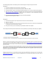
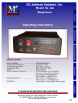
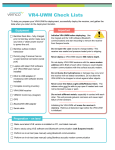
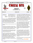
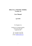
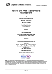
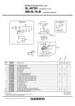
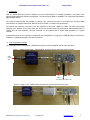
NGA Noise Gain Analyser User Guide v1.1
1 August 2015
1) Introduction
NGA is a broad band linear receiver designed for noise measurements, for example preamplifier / transverter noise
figure and gain testing and antenna development. The input range is 2MHz to 1800MHz. The output noise bandwidth is
approximately 90KHz.
The output is balanced 600 ohm suitable for driving a PC soundcard line input or a sensitive low frequency RMS
millivoltmeter, for example Racal 9300, Marconi 2610, HP 3400A, or similar low cost instrument.
An external local oscillator is required at the test frequency in the range +4dBm to +7dBm. The NGA noise output
spectrum is the addition of two ‘slots’ either side of the local oscillator frequency and spaced approximately 80kHz to
170kHz from the local oscillator. The local oscillator can be supplied from a bench signal generator or a crystal
oscillator.
A calibrated noise source is required to complete the test configuration. If a high gain (>30dB) amplifier or transverter is
measured, a calibrated attenuator may also be required.
2) Test configuration example
The photographs below demonstrate a G4BAO wide band low noise preamplifier device under test (DUT).
Photo 1 – Measurement stage 1. Records NGA ‘own noise figure’ and noise reference levels.
Noise
source
drive
LO
+5dBm
+12v
AF output to mV meter or PC
Photo 2 – Stage 2. DUT (G4BAO LNA) introduced to measure gain and noise figure.
NGA Noise Gain Analyser User Guide v1.1
1 August 2015.
www.g8fek.com
1
The following steps provide a useful starting routine for determining the noise figure and gain of the DUT.
Photograph 1.
1) Connect the calibrated noise source directly to the NGA input.
2) Inject the local oscillator at the test frequency at between +4dBm and +7dBm.
3) Connect the NGA AF output to a low frequency RMS millivoltmeter or PC running a soundcard level application.
4) Apply 12v to the NGA. It demands approximately 75mA. Record the noise level in the NGA spreadsheet at
http://www.g8fek.com/downloads3.htm . Expect a level in the range 200 – 300uV. Alternatively, use ‘NFM’
soundcard based software from Owen Duffy VK1OD.
5) Turn on the noise source and record the noise level in the NGA spreadsheet.
Expect a level in the range 250 – 500uV.
Photograph 2.
1) Connect the DUT (Device Under Test) between the noise source and the NGA input.
2) Apply 12v to the NGA.
3) Record the noise level with the noise source off and then with the noise source on and enter to the spreadsheet
or using Owens’ NFM soundcard based software.
4) DUT gain and noise figure are calculated by the spreadsheet or NFM. Test complete!
The two stage measurement process described above can be speeded up by introducing coaxial relays (not supplied):
Noise source
B
A
DUT
C
BPF**
NGA
PAD*
D
* The attenuator is required if the DUT gain exceeds 30dB.
** Not required for LNA tests. A band pass filter (BPF) may be required for transverter testing to attenuate local oscillator feed through.
Measure or estimate the attenuation at the test frequency of each of the signal paths A>B, A>C and D>B. These values
can be entered into the NFM software available from Owen Duffy at http://owenduffy.net/software/nfm/index.htm to
calculate DUT gain and noise figure. Owen’s NFM also outputs state drivers to the PC ports to control the relays and the
noise source drive.
The two stage measurement procedure described above is common to most commercial noise figure instruments and is
said to provide ‘second stage’ correction. The second stage, NGA in this case, noise figure is factored into the DUT
performance result. The supporting literature from Owen on NFM plus the HP Application Notes referenced there,
provide a full explanation of the technique.
Pulsing the noise source at 1 or 2Hz allows real time noise figure optimization by viewing the cold / hot noise levels
output from NGA in a rolling window as provided in SignalMeasure PC soundcard based software from Andy Talbot at
www.G4JNT.com/dspsw.htm .
NGA Noise Gain Analyser User Guide v1.1
1 August 2015.
www.g8fek.com
2
3) Quick look noise figure tests (without DUT gain results)
In common with instruments like the HP 8970, NGA will provide an ‘uncorrected’ DUT noise figure measurement by
observing the ‘Y’ value (noise cold to noise hot) in a single step. NGA is very sensitive with a self noise figure (see
detailed specification) of below 4dB over the majority of the input bandwidth. Consequently direct DUT Y values produce
useful accuracy DUT noise figure results for a >15dB gain DUT with noise figure above 1dB.
With the known NGA noise figure from data or your own test configuration results, second stage correction can be
carried out using the calculator at http://www.minicircuits.com/pages/mcl_nf_calc.html .
The calibrated noise source may of course be substituted with a celestial noise source in your test configuration.
4)
NGA contribution to noise figure measurement uncertainty
Our web pages have links to a number of respected learned papers on understanding and minimizing NF measurement
uncertainty.
Using NGA, a first pass review of the obvious contributions would include noise source ENR calibration accuracy, NGA
linearity and noise power measurement uncertainty of the display device.
RMS measurement of noise and associated issues see http://owenduffy.net/calc/nmuc.htm
Some practical measurement results may help provide give just an indicator of the accuracy you can expect.
Comparisons of noise figure and gain test results on a Miteq 5MHz – 1500MHz LNA (~39dB) with 10dB output pad:
28 MHz
432 MHz
1296 MHz
HP 8970A/346A
GAIN dB
HP 8970A/346A
NF dB
NGA / HP 346A / NFM
GAIN dB
NGA / HP 346A / NFM
NF dB
28.14
28.67
28.56
1.37
1.74
2.71
28.0
28.7
29.2
1.49
1.89
2.82
NGA output to (standard soundcard) PC with VK1OD NFM software. 5 second measurement interval.
The above bench mark comparison demonstrates NGA operating with a 29dB gain DUT.
5)
Hints and tips
a) Environmental noise and off air signals can cause interference to noise figure testing. Even radiation from a PC
comfortably under the regulatory Class B emission limit may disrupt your test result. Be aware of off air signals
close to your measurement frequency and take measures to exclude them from your test configuration or move
the test frequency slightly. Mounting NGA in a screened enclosure improves immunity to off air ambient. The
PCB underside is a full flood ground plane and can be mounted directly to the enclosure wall.
b) We have found that some energy saving light bulb drivers may be troublesome to the NGA baseband stages,
although this only appears to be a problem at very close spacings on the bench.
c) When testing transverters ensure the local oscillator feed through that appears at the transverter IF port is at
manageable level for NGA. The permissible CW power for NGA is very similar to HP 8970. Signals >-35dBm
will cause errors to be introduced in the measurement. A simple band pass filter at the IF frequency is usually
sufficient to overcome this.
d) Whilst NGA accommodates up to 35dB external gain with a 5dB ENR noise source, the use of attenuators
following the DUT can improve results accuracy. VK1OD NFM software has user input fields to enter attenuator
values.
NGA Noise Gain Analyser User Guide v1.1
1 August 2015.
www.g8fek.com
3
Performance specification
Typical performance at +7dBm local oscillator drive (from crystal oscillator). 20⁰C.
DUT = Device Under Test.
Power requirements
11.0 – 15.0v @ 75mA
Input frequency
2MHz to 1800MHz
Local oscillator input (50R)
+4dBm to +7dBm
Max external gain (DUT)
35dB between noise source (5dB ENR) and NGA input.
Typical noise floor at AF output
Measured into 600 ohm 20MHz millivoltmeter, NGA input terminated in 50R.
10MHz
432MHz
1296MHz
1800MHz
290uV RMS
250uV RMS
200uV RMS
165uV RMS
Noise output -3dB bandwidth
70Hz – 90kHz (600R output impedance)
Input noise bandwidth
180kHz
Typical NGA input noise figure
2MHz
28MHz
50MHz
144MHz
432MHz
902MHz
1296MHz
1500MHz
1800MHz
<3dB
2.53dB
2.50dB
2.61dB
2.95dB
2.87dB
3.97dB
6.08dB
9.29dB
Input VSWR
(PCB mounted SMA socket)
<1.5:1 2MHz – 1800MHz
Max permissible CW power at input
(LO feedthrough from DUT)
-35dBm
Max (no damage) input level
+13dBm. ±25v DC.
NGA Noise Gain Analyser User Guide v1.1
1 August 2015.
www.g8fek.com
4