1
User Manual
SmartWireDT Gateway
EU5CSWDETHERCAT
Hilscher Gesellschaft für Systemautomation mbH
www.hilscher.com
DOC140901UM02EN | Revision 2 | English | 201506 | Released | Public
Table of contents
2/99
Table of contents
1
2
3
4
Introduction............................................................................................................................... 5
1.1
About this document......................................................................................................... 5
1.1.1
Description of the contents ................................................................................ 5
1.1.2
List of revisions.................................................................................................. 5
1.1.3
Conventions in this document ........................................................................... 6
1.2
Versions of devices, firmware, software tools, drivers and device description files ......... 7
1.3
Software package............................................................................................................. 8
1.3.1
Overview............................................................................................................ 8
1.3.2
Contents of the product DVD............................................................................. 8
1.3.3
How to use the product DVD ........................................................................... 10
1.3.4
Notes on installing the USB Driver .................................................................. 11
1.4
Documentation overview ................................................................................................ 12
1.5
Legal notes ..................................................................................................................... 13
1.5.1
Copyright ......................................................................................................... 13
1.5.2
Important notes................................................................................................ 13
1.5.3
Exclusion of liability ......................................................................................... 14
1.5.4
Warranty .......................................................................................................... 14
1.5.5
Export regulations............................................................................................ 15
1.5.6
Registered Trademarks ................................................................................... 15
Safety ....................................................................................................................................... 16
2.1
General note................................................................................................................... 16
2.2
Intended use................................................................................................................... 16
2.3
Personnel qualification ................................................................................................... 16
2.4
References safety ......................................................................................................... 16
2.5
Safety instructions to avoid personal injury .................................................................... 17
2.5.1
Electrical shock hazard.................................................................................... 17
2.5.2
Danger of unintended starting up of machines................................................ 17
2.6
Safety instructions to avoid property damage ................................................................ 18
2.6.1
General safety instructions concerning supply voltage ................................... 18
2.6.2
Device destruction by exceeding allowed supply voltage................................ 18
2.6.3
Electrostatic sensitive device........................................................................... 19
2.7
Labeling of safety messages .......................................................................................... 20
Description of the EU5CSWDETHERCAT gateway ........................................................... 21
3.1
Function.......................................................................................................................... 21
3.2
Configuration .................................................................................................................. 22
3.2.1
SmartWireDT configuration ............................................................................ 22
3.2.2
EtherCAT configuration ................................................................................... 23
3.3
Interfaces........................................................................................................................ 23
3.4
Diagnosis........................................................................................................................ 23
3.5
Firmware and device description files ............................................................................ 23
Requirements for operation .................................................................................................. 24
4.1
Network systems ............................................................................................................ 24
4.2
Power supply .................................................................................................................. 24
4.2.1
POW power connection................................................................................... 25
4.2.2
AUX power connection .................................................................................... 25
SmartWireDT Gateway | EU5CSWDETHERCAT
DOC140901UM02EN | Revision 2 | English | 201506 | Released | Public
© Hilscher 2015
Table of contents
5
3/99
Device picture, connectors and LEDs .................................................................................. 26
5.1
Device picture................................................................................................................. 26
5.2
Positions and meaning of the LEDs ............................................................................... 27
5.2.1
Positions of the LEDs ...................................................................................... 27
5.2.2
Description of the LEDs................................................................................... 28
5.3
Pinning of the RealTime Ethernet interface .................................................................. 30
5.4
Device type label ............................................................................................................ 30
6
Getting started ........................................................................................................................ 31
7
Installing gateway................................................................................................................... 32
8
9
7.1
Safety messages ............................................................................................................ 32
7.2
Mounting gateway ......................................................................................................... 33
7.2.1
Mounting gateway onto top hat rail.................................................................. 33
7.2.2
Removing gateway from top hat rail ................................................................ 35
7.3
Connecting gateway to power supply............................................................................. 36
7.4
Connecting SmartWireDT ............................................................................................ 38
7.5
Connecting EtherCAT ................................................................................................... 39
7.6
EMCconformant wiring of the network .......................................................................... 40
Configuring gateway .............................................................................................................. 41
8.1
Overview ........................................................................................................................ 41
8.2
Configuring SmartWireDT network in gateway (creating target configuration) ............. 41
8.2.1
Overview.......................................................................................................... 41
8.2.2
Prerequisites ................................................................................................... 42
8.2.3
Stepbystep instructions ................................................................................. 42
8.3
Configuring gateway in EtherCAT .................................................................................. 43
8.3.1
Device description files.................................................................................... 43
8.3.2
Configuring gateway in TwinCAT ................................................................... 44
Parameterization..................................................................................................................... 51
9.1
Process data .................................................................................................................. 51
9.2
Configuring SmartWireDT Coordinator ......................................................................... 52
9.2.1
Overview.......................................................................................................... 52
9.2.2
Prerequisites.................................................................................................... 54
9.2.3
Stepbystep instructions ................................................................................. 54
9.3
Configuration data of the SWD devices ......................................................................... 57
9.3.1
Overview.......................................................................................................... 57
9.3.2
Configuring device options of SmartWireDT devices in TwinCAT ................. 58
9.3.3
Configuring device parameters (sensor parameters of I/O modules).............. 65
10 Acyclical communication ...................................................................................................... 72
10.1 Overview ........................................................................................................................ 72
10.2 Read request: reading data of an SWD Slave ............................................................... 74
10.2.1 Activating read request.................................................................................... 74
10.2.2 Querying the state of the read request ............................................................ 74
10.2.3 Example of a read request .............................................................................. 76
10.3 Write request: writing data in an SWD Slave ................................................................. 77
10.3.1 Activating write request ................................................................................... 77
10.3.2 Querying the state of the write request............................................................ 78
10.3.3 Example of a write request .............................................................................. 79
SmartWireDT Gateway | EU5CSWDETHERCAT
DOC140901UM02EN | Revision 2 | English | 201506 | Released | Public
© Hilscher 2015
Table of contents
4/99
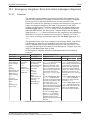
10.4 Emergency telegrams: Error and status messages (diagnosis) ..................................... 80
10.4.1 Overview.......................................................................................................... 80
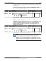
10.4.2 Error messages (diagnosis) of individual SWD slaves (Entry Type = 0x70) ... 81
10.4.3 Messages generated by the gateway (Entry Type = 0xFF)............................. 83
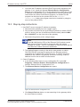
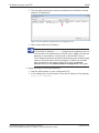
11 Updating firmware with TwinCAT System Manager............................................................ 85
11.1 Overview ........................................................................................................................ 85
11.2 Prerequisites .................................................................................................................. 85
11.3 Stepbystep instructions ................................................................................................ 86
12 Firmware recovery via HTTP ................................................................................................. 88
12.1 Overview ........................................................................................................................ 88
12.2 Prerequisites .................................................................................................................. 88
12.3 Stepbystep instructions ................................................................................................ 89
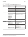
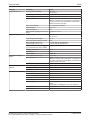
13 Technical data......................................................................................................................... 93
13.1 Technical data EU5CSWDETHERCAT gateway ......................................................... 93
13.2 Technical data EtherCAT slave ...................................................................................... 95
List of figures .......................................................................................................................... 96
List of tables ........................................................................................................................... 97
Contacts .................................................................................................................................. 99
SmartWireDT Gateway | EU5CSWDETHERCAT
DOC140901UM02EN | Revision 2 | English | 201506 | Released | Public
© Hilscher 2015
Introduction
1
5/99
Introduction
1.1
1.1.1
About this document
Description of the contents
This manual describes the Hilscher EU5CSWDETHERCAT
SmartWireDT Gateway. Here you will find information on how to install,
configure and operate the gateway.
This manual is intended for automation technicians and engineers. Detailed
knowledge of the EtherCAT® RealTime Ethernet protocol is presumed. In
addition, readers should also be familiar with the TwinCAT System
Manager and the SmartWireDT system.
Important:
Ø To avoid personal injuries or damage of electrical devices,
please read this manual carefully before installing and using the
EU5CSWDETHERCAT Gateway.
Ø Please first read the chapter Safety [} page 16].
1.1.2
List of revisions
Revision
Date
Revisions
1
20150317
Created
2
20150622
Design of safety messages updated
Section Error messages (emergency telegrams) revised and
renamed as Emergency telegrams: Error and status messages
(diagnosis) [} page 80].
Table 1: List of revisions
SmartWireDT Gateway | EU5CSWDETHERCAT
DOC140901UM02EN | Revision 2 | English | 201506 | Released | Public
© Hilscher 2015
Introduction
1.1.3
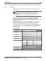
6/99
Conventions in this document
Notes, operation instructions and results of operation steps are marked as
follows:
Notes
Note:
<important note>
Note:
<simple note>
<note, where to find further information>
Operation instructions
1. <operational step>
Ø <instruction>
2. <operational step>
Ø <instruction>
Results
<intermediate result>
<final result>
For a description of the labeling of Safety Messages, see section Labeling
of safety messages [} page 20].
SmartWireDT Gateway | EU5CSWDETHERCAT
DOC140901UM02EN | Revision 2 | English | 201506 | Released | Public
© Hilscher 2015
Introduction
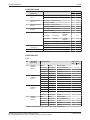
1.2
7/99
Versions of devices, firmware, software tools, drivers and
device description files
The hardware revisions and software versions functionally belong together.
This means that certain revisions of the hardware of the gateway need
certain versions of firmware, software and drivers, in order to function
properly. This section lists the hardware revisions and the versions of the firmware,
the configuration software and the drivers which functionally belong
together and to which all instructions in this manual refer.
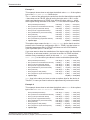
Device and firmware
This manual refers to the following hardware revision and firmware version
of the EU5CSWDETHERCAT Gateway:
Device type name
Protocol
Part number
Hardware
revision
Firmware
Firmware
version
EU5CSWDETHERCAT
EtherCAT® slave
9233.922
3
E030F0U0.nxf
1.0.x.x
Table 2: Reference to hardware and firmware
Software tools
This manual refers to the following software versions:
Software
Manufacturer
Version
SWDAssist
Eaton
2.xx
TwinCAT System Manager
Beckhoff Automation GmbH
2.11
Table 3: Reference to software tools
Drivers
This manual refers to the following driver versions:
Driver
File name
Version
Windows USB Driver
usbser.sys
Depending on
Windows version
Table 4: Reference to drivers
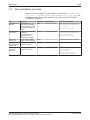
Device description files
This manual refers to the following device description files (ESI EtherCAT®
Slave Information files):
Device description file
File name
ESI for EU5CSWDETHERCAT gateway
Hilscher_EU5CSWDETHERCAT_XXXXXXXX.xml
ESI for SWD participants
Eaton_EU5CSWDETHERCAT_Modules_XXXXXXXX.xml
ESI for SWD partner devices by Phoenix
Phoenix_EU5CSWDETHERCAT_Modules_XXXXXXXX.xml
ESI for SWD partner devices by Wöhner
Woehner_EU5CSWDETHERCAT_Modules_XXXXXXXX.xml
Table 5: Reference to device description files
SmartWireDT Gateway | EU5CSWDETHERCAT
DOC140901UM02EN | Revision 2 | English | 201506 | Released | Public
© Hilscher 2015
Introduction
1.3
1.3.1
8/99
Software package
Overview
Hilscher offers the optional software package EU5CSWDSW (part
number 3233.920) for SmartWireDT Gateways. The package features the
SmartWireDT Gateway Solutions product DVD and a MiniUSB cable.
The SmartWireDT Gateway Solutions product DVD contains the
EtherCAT® Slave Information files (ESI) necessary for configuring the
EU5CSWDETHERCAT gateway within the EtherCAT® network. If you do
not need the whole package with the USB cable, you can download the
contents of the product DVD separately and free of charge as ZIP file from
our website www.hilscher.com under Products > Partner Products >
SmartWireDT > EU5CSWDETHERCAT > Downloads > Software.
Note:
The TwinCAT System Manager used in the commissioning example
in this document is not included on the product DVD. TwinCAT can
be obtained from the Beckhoff Automation GmbH.
1.3.2
Contents of the product DVD
The SmartWireDT Gateway Solutions product DVD contains software for
all types of SmartWireDT gateways. Depending on the gateway type you
are using, you will need only certain features of the DVD.
The product DVD includes:
·
Device description files
·
Firmware
·
Eaton SWDAssist software
·
Wizard for installing the software available on the DVD and for
downloading the latest version of the SWDAssist software from the
internet
·
Installation program for USB driver (USB driver is needed for
connecting the gateway to a PC in order to use the Eaton SWDAssist
software)
·
Installation program for the Hilscher Ethernet Device Configuration Tool
·
Documentation in PDF format
·
Installation program for Adobe Reader
SmartWireDT Gateway | EU5CSWDETHERCAT
DOC140901UM02EN | Revision 2 | English | 201506 | Released | Public
© Hilscher 2015
Introduction
9/99
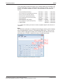
The product DVD has the following directories:
Directory
Contents
Documentation
PDF manuals in German and English and installation program for Adobe Reader
EDS
Electronic device description files and bitmaps, to be imported directly into Master/
Controller configuration software.
Firmware
Loadable gateway firmware
fscommand
Files for start screen of product DVD
Setups & Drivers
SWDAssist software
Folder: SWDAssist
Wizard for installing the software available on the DVD and for downloading the latest
version of the SWDAssist software from the internet
Folder: Setup
Installation program for Ethernet Device Configuration Tool
Folder: EnDeviceCfg
Installation program (setup.exe) and .INF and .CAT files for Windows USB driver.
Folder: USB Driver
Table 6: Directory of the product DVD
Note:
You can use the wizard on the product DVD to download updates of
the Eaton SWDAssist software, or you can download SWDAssist
directly from the www.moeller.net website under Support >
Download Center. Direct link: http://downloadcenter.moeller.net/en/software.a487d8b7‐
da91‐486f‐b3ba‐a7ca2035db99
SmartWireDT Gateway | EU5CSWDETHERCAT
DOC140901UM02EN | Revision 2 | English | 201506 | Released | Public
© Hilscher 2015
Introduction
1.3.3
10/99
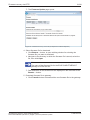
How to use the product DVD
Insert the SmartWireDT Gateway Solutions product DVD into the DVD
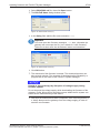
drive of your configuration PC. If the auto start function of your DVD drive is enabled, the start screen of
the DVD automatically opens. You can also start the DVD by double
clicking the SmartWire.exe file in the root directory of the DVD.
In the menu of the start screen of the DVD, click Install Planning and
Configuration Tools to open a wizard for installing the software programs
stored on the DVD. The wizard also helps you to download the latest
version of the Eaton planning software SWDAssist from the internet. It
automatically checks for already installed software components (which e. g.
might have been installed for an earlier project), and lists the missing
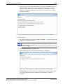
components accordingly. The following options might be offered:
·
USB Driver: installs USB driver for Windows on your PC.
·
Download Center SWDAssist (manual update): connects your
browser to a web page where you can download the latest version of
the SWDAssist software.
·
SWD Planning Software SWDAssist Vx.xx: installs the SWDAssist
software version provided on the DVD.
·
Ethernet Device Scanner/Configuration Tool: installs the Hilscher
Ethernet Device Configuration Tool.
·
GSDML, EDS, ESI files (HTML page): opens a web page containing
links to the device description files.
In the main menu of the start screen of the DVD, you can furthermore open
a web page which provides an overview of all available documents (menu
Documentation). You can also directly open the folder containing the
device description files (menu Open Electronic Device Description Files
Directory).
SmartWireDT Gateway | EU5CSWDETHERCAT
DOC140901UM02EN | Revision 2 | English | 201506 | Released | Public
© Hilscher 2015
Introduction
1.3.4
11/99
Notes on installing the USB Driver
If you intend to use the SWDAssist software, you should first install the
USB driver on your PC before you connect the gateway via USB.
To install the USB driver from the DVD, choose Install Planning and
Configuration Tools in the DVD menu to open the installation wizard, and
then select the USB driver option. As an alternative, you can use the
Windows Explorer to open the Setups & Drivers\USB Driver folder on
the DVD, and then doubleclick the setup.exe file. Just follow the
instructions of the installation routine afterwards.
Note:
Under Windows XP, the installation process is not yet finished by
the setup. The installation process has to be completed in the
Found new Hardware Wizard, which automatically opens when
you connect the gateway to a PC via USB cable for the first time
(see below).
Windows XP
When you connect the gateway via USB for the first time to a PC running
under Windows XP, the Found New Hardware Wizard opens:
Ø Answer the question Can Windows connect to Windows Update…?,
with No, not this time. Then click Next button.
Ø If you have already carried out the setup of the USB driver (as
recommended), you can ignore the wizard’s request to insert a CD or
floppy disk. Answer the What do you want the wizard to do? question
by selecting the Install the software automatically option, then click
Next button.
Ø After the installation is complete, click Finish button.
Windows 7 and 8
The USB connection is instantly operative under Windows 7 and 8 if you
have carried out the setup of the USB driver before first connecting the
USB cable (as recommended).
Uninstall USB Driver
If you want to remove the USB driver from a PC running under Windows
XP, choose Start menu > Control Panel > Add or Remove Programs,
then select: Windows Driver Package – Hilscher GmbH (hilusbser) Ports entry.
Click Change/Remove button to uninstall the driver.
Under Windows 7 and 8, choose Start menu > Control Panel > Uninstall
a program, then select: Windows Driver Package – Hilscher GmbH (hilusbser) Ports entry.
Click Uninstall/Change button to uninstall the driver.
SmartWireDT Gateway | EU5CSWDETHERCAT
DOC140901UM02EN | Revision 2 | English | 201506 | Released | Public
© Hilscher 2015
Introduction
1.4
12/99
Documentation overview
Besides this user manual at hand (path on product DVD: Documentation
\english\2. Hardware\EU5CSWDETHERCAT UM xx EN.pdf), the
following documents are also relevant for the user of the EU5CSWD
ETHERCAT Gateway:
Title
Contents
Publisher Document ID
Path on product DVD
SmartWireDT
Modules
Information on
engineering, installation
and programming of the
individual SmartWireDT
slaves.
Eaton
MN05006001ZEN
Documentation\english\
3.SmartWireDT\SmartWire
DT – Units\
MN05006001Z_EN.pdf
SmartWireDT
The System
Information on function,
installation,
commissioning and
diagnostics of the
SmartWireDT system.
Eaton
MN05006002ZEN
Documentation\english\
3.SmartWireDT\SmartWire
DT The System\
MN05006002Z_EN.pdf
SWDAssist Online help
Online help for SWD
Assist planning software
Eaton
Included in SWDAssist software
TwinCAT System Manager
Online help
Online help TwinCAT
System Manager
Beckhoff
Included in TwinCAT software
Wiring
Instructions
EtherCAT
Wiring instructions for
EtherCAT® devices
Hilscher
DOC121104UMxxEN
Documentation\english
\5.Installation
Instructions\
Wiring Instructions
EtherCAT UM 01 EN.pdf
Table 7: Documentation overview
SmartWireDT Gateway | EU5CSWDETHERCAT
DOC140901UM02EN | Revision 2 | English | 201506 | Released | Public
© Hilscher 2015
Introduction
1.5
1.5.1
13/99
Legal notes
Copyright
© Hilscher 2015, Hilscher Gesellschaft für Systemautomation mbH
All rights reserved.
The images, photographs and texts in the accompanying material (user
manual, accompanying texts, documentation, etc.) are protected by
German and international copyright law as well as international trade and
protection provisions. You are not authorized to duplicate these in whole or
in part using technical or mechanical methods (printing, photocopying or
other methods), to manipulate or transfer using electronic systems without
prior written consent. You are not permitted to make changes to copyright
notices, markings, trademarks or ownership declarations. The included
diagrams do not take the patent situation into account. The company
names and product descriptions included in this document may be
trademarks or brands of the respective owners and may be trademarked or
patented. Any form of further use requires the explicit consent of the
respective rights owner.
1.5.2
Important notes
The user manual, accompanying texts and the documentation were created
for the use of the products by qualified experts, however, errors cannot be
ruled out. For this reason, no guarantee can be made and neither juristic
responsibility for erroneous information nor any liability can be assumed.
Descriptions, accompanying texts and documentation included in the user
manual do not present a guarantee nor any information about proper use
as stipulated in the contract or a warranted feature. It cannot be ruled out
that the user manual, the accompanying texts and the documentation do
not correspond exactly to the described features, standards or other data of
the delivered product. No warranty or guarantee regarding the correctness
or accuracy of the information is assumed.
We reserve the right to change our products and their specification as well
as related user manuals, accompanying texts and documentation at all
times and without advance notice, without obligation to report the change.
Changes will be included in future manuals and do not constitute any
obligations. There is no entitlement to revisions of delivered documents.
The manual delivered with the product applies.
Hilscher Gesellschaft für Systemautomation mbH is not liable under any
circumstances for direct, indirect, incidental or followon damage or loss of
earnings resulting from the use of the information contained in this
publication.
SmartWireDT Gateway | EU5CSWDETHERCAT
DOC140901UM02EN | Revision 2 | English | 201506 | Released | Public
© Hilscher 2015
Introduction
1.5.3
14/99
Exclusion of liability
The software was produced and tested with utmost care by Hilscher
Gesellschaft für Systemautomation mbH and is made available as is. No
warranty can be assumed for the performance and flawlessness of the
software for all usage conditions and cases and for the results produced
when utilized by the user. Liability for any damages that may result from the
use of the hardware or software or related documents, is limited to cases of
intent or grossly negligent violation of significant contractual obligations.
Indemnity claims for the violation of significant contractual obligations are
limited to damages that are foreseeable and typical for this type of contract.
It is strictly prohibited to use the software in the following areas:
·
for military purposes or in weapon systems;
·
for the design, construction, maintenance or operation of nuclear
facilities;
·
in air traffic control systems, air traffic or air traffic communication
systems;
·
in life support systems;
·
in systems in which failures in the software could lead to personal injury
or injuries leading to death.
We inform you that the software was not developed for use in dangerous
environments requiring failproof control mechanisms. Use of the software
in such an environment occurs at your own risk. No liability is assumed for
damages or losses due to unauthorized use.
1.5.4
Warranty
Although the hardware and software was developed with utmost care and
tested intensively, Hilscher Gesellschaft für Systemautomation mbH does
not guarantee its suitability for any purpose not confirmed in writing. It
cannot be guaranteed that the hardware and software will meet your
requirements, that the use of the software operates without interruption and
that the software is free of errors. No guarantee is made regarding
infringements, violations of patents, rights of ownership or the freedom from
interference by third parties. No additional guarantees or assurances are
made regarding marketability, freedom of defect of title, integration or
usability for certain purposes unless they are required in accordance with
the law and cannot be limited. Warranty claims are limited to the right to
claim rectification.
SmartWireDT Gateway | EU5CSWDETHERCAT
DOC140901UM02EN | Revision 2 | English | 201506 | Released | Public
© Hilscher 2015
Introduction
1.5.5
15/99
Export regulations
The delivered product (including the technical data) is subject to export or
import laws as well as the associated regulations of different counters, in
particular those of Germany and the USA. The software may not be
exported to countries where this is prohibited by the United States Export
Administration Act and its additional provisions. You are obligated to
comply with the regulations at your personal responsibility. We wish to
inform you that you may require permission from state authorities to export,
reexport or import the product.
1.5.6
Registered Trademarks
Adobe Reader® is a registered trademark of Adobe Systems Incorporated.
EtherCAT® is registered trademark and patented technology, licensed by
Beckhoff Automation GmbH, Germany.
SmartWireDT® is a registered trademark of Eaton Corporation.
TwinCAT® is a registered trademark of Beckhoff Automation GmbH,
Germany.
Windows® XP, Windows® 7 and Windows® 8 are registered trademarks of
the Microsoft Corporation.
All other mentioned trademarks are property of their respective legal
owners.
SmartWireDT Gateway | EU5CSWDETHERCAT
DOC140901UM02EN | Revision 2 | English | 201506 | Released | Public
© Hilscher 2015
Safety
2
2.1
16/99
Safety
General note
The user manual, all accompanying texts and the documentation are
written for the use of the products by educated personnel. When using the
products, all safety instructions, property damage messages and all valid
legal regulations have to be observed. Technical knowledge is presumed.
The user has to assure that all legal regulations are obeyed.
2.2
Intended use
The purpose of the EU5CSWDETHERCAT Gateway described in this
user manual is to create a connection between SmartWireDT slaves and
an EtherCAT® master in an overriding EtherCAT® network.
2.3
Personnel qualification
The gateway must be installed, configured and removed by qualified
personnel only. Jobspecific technical skills for people professionally
working with electricity must be present concerning the following issues:
2.4
·
Safety and health at work
·
Mounting and connecting of electrical equipment
·
Measurement and analysis of electrical functions and systems
·
Evaluation of the safety of electrical systems and equipment
·
Installing and configuring IT systems
References safety
[S1]
ANSI Z535.62006 American National Standard for Product Safety Information in
Product Manuals, Instructions, and Other Collateral Materials
[S2]
IEC 609501, Information technology equipment Safety Part 1: General requirements,
(IEC 609501:2005, modified); German Edition EN 609501:2006
[S3]
EN 6134051 and EN 6134052 as well as IEC 6134051 and IEC 6134052
SmartWireDT Gateway | EU5CSWDETHERCAT
DOC140901UM02EN | Revision 2 | English | 201506 | Released | Public
© Hilscher 2015
Safety
2.5
17/99
Safety instructions to avoid personal injury
To ensure your own personal safety and to avoid personal injury, you must
read, understand and follow the following safety instructions in this manual
and all warning messages before you install and operate the gateway.
2.5.1
Electrical shock hazard
Take care of the following safety measures before installing or uninstalling
the gateway:
·
First disconnect the power plug of the device.
·
Make sure that the device is disconnected from the power supply.
·
Cover or enclose neighboring units that are live.
Devices that are designed for mounting in housings or control cabinets
must only be operated and controlled after they have been installed with
the housing closed. Desktop or portable units must only be operated and
controlled in enclosed housings.
2.5.2
Danger of unintended starting up of machines
·
Install automation devices and related operating elements in a way that
they are well protected against unintentional operation.
·
Emergency stop devices complying with IEC/EN 602041 must be
effective in all operating modes of the automation devices. Unlatching
the emergencystop devices must not cause restart.
·
You must take safety precautions (emergency switching off) in the
external circuitry of the gateway and any power modules type EU5C
SWDPF11 or EU5CSWDPF21 that are used. To do so, plan to
switch off the power supply to the contactor coils AUX.
·
Measures should be taken to ensure the proper restart of programs
interrupted after a voltage dip or failure. This should not cause
dangerous operating states even for a short time. If necessary,
emergency stop devices should be implemented.
·
Wherever faults in the automation system may cause damage to
persons or property, external measures must be implemented to ensure
a safe operating state in the event of a fault or malfunction (for example,
by means of separate limit switches, mechanical interlocks etc.).
SmartWireDT Gateway | EU5CSWDETHERCAT
DOC140901UM02EN | Revision 2 | English | 201506 | Released | Public
© Hilscher 2015
Safety
2.6
18/99
Safety instructions to avoid property damage
To avoid damage to your gateway or your communication system, you
must read, understand and follow the following safety instructions and all
safety instructions and warnings in this manual concerning property
damage, before you install and operate the gateway.
2.6.1
2.6.2
General safety instructions concerning supply voltage
·
In safetyrelevant applications the power supply providing power to the
SmartWireDT system must feature a PELV power feed module
(protective extra low voltage).
·
Switch off the power supply if you are reconnecting slaves in the
SmartWireDT system or reconnecting the ribbon cable connection.
Otherwise the SmartWireDT slaves can be destroyed!
·
The gateway has protection against polarity reversal for the 24VDC
POW supply. However, if the gateway is connected via the serial
interface to an earthed device (for example to a PC), the gateway can
be destroyed, if the polarity of the power supply is reversed!
·
The functional earth (FE) must be connected to the protective earth
(PE) or to the potential equalization. The system installer is responsible
for implementing this connection.
·
Connecting cables and signal lines should be installed so that inductive
or capacitive interference does not impair the automation functions.
·
Suitable safety hardware and software measures should be
implemented for the I/O interface so that a line or wire breakage on the
signal side does not result in undefined states in the automation
devices.
Device destruction by exceeding allowed supply voltage
The gateway must only be operated with the specified supply voltage.
·
Make sure that the limits of the allowed range for the supply voltage are
not exceeded. A supply voltage above the upper limit can cause severe
damage of the gateway!
·
A supply voltage below the lower limit can cause malfunction of the
gateway!
·
Ensure a reliable electrical isolation of the low voltage for the 24 volt
supply. Only use power supply units complying with IEC 60364441
(VDE 0100 Part 410) or HD 384.4.41 S2.
The allowed range for the supply voltage is indicated in section Technical
data EU5CSWDETHERCAT gateway [} page 93]
SmartWireDT Gateway | EU5CSWDETHERCAT
DOC140901UM02EN | Revision 2 | English | 201506 | Released | Public
© Hilscher 2015
Safety
2.6.3
19/99
Electrostatic sensitive device
The gateway is sensitive to electrostatic discharge, which can cause
internal damage and affect its normal operation. Therefore adhere to the
necessary safety precautions for components that are vulnerable to
electrostatic discharge when you install or remove the gateway. Follow the
guidelines listed hereafter when you handle the gateway:
·
Touch a grounded object to discharge potential static before you handle
the gateway.
·
Wear an approved grounding wrist strap.
·
If possible, use a staticsafe workstation.
·
When not in use, store the device in appropriate staticsafe packaging.
SmartWireDT Gateway | EU5CSWDETHERCAT
DOC140901UM02EN | Revision 2 | English | 201506 | Released | Public
© Hilscher 2015
Safety
2.7
20/99
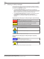
Labeling of safety messages
In this document the safety instructions and property damage messages
are designed according both to the internationally used safety conventions
as well as to the ANSI Z535 standard.
·
The Section Safety Messages at the beginning of a chapter are
pinpointed particularly and highlighted by a signal word according to the
degree of endangerment. The kind of danger is specified exactly by the
safety message text and optionally by a specific safety sign.
·
The Integrated Safety Messages embedded in operating instructions
are highlighted by a signal word according to the degree of
endangerment. In the safety message, the nature of the hazard is
indicated.
Signal words and safety signs in safety messages on personal injury
Signal word
Meaning
Indicates a direct hazard with high risk, which will have as consequence
death or grievous bodily harm if it is not avoided.
Indicates a possible hazard with medium risk, which will have as
consequence death or (grievous) bodily harm if it is not avoided.
Indicates a minor hazard with medium risk, which could have as
consequence personal injury if it is not avoided.
Table 8: Signal words in safety messages on personal injury
Safety sign
Sort of warning or principle
Warning of lethal electrical shock
Principle: Disconnect the power plug
Table 9: Safety signs in messages on personal injury
Signal words and safety signs in safety messages on property
damage
Signal word
Meaning
Indicates a property damage message
Table 10: Signal words in safety messages on property damage
Safety sign
Sort of warning or principle
Warning of property damage by electrostatic discharge
Table 11: Safety signs in safety messages on property damage
SmartWireDT Gateway | EU5CSWDETHERCAT
DOC140901UM02EN | Revision 2 | English | 201506 | Released | Public
© Hilscher 2015
Description of the EU5CSWDETHERCAT gateway
3
3.1
21/99
Description of the EU5CSWDETHERCAT gateway
Function
The EU5CSWDETHERCAT gateway integrates a SmartWireDT network
into an EtherCAT® network. The gateway creates a data connection
between the participants (the slave devices) of the subordinate SmartWire
DT network and the master device or PLC of the super ordinate EtherCAT®
network.
The gateway acts as master (a.k.a. “Coordinator”) in the SmartWireDT
network on the one hand, and on the other hand as modular slave in the
EtherCAT® network. It thereby presents each connected SmartWireDT
participant as individual module to the EtherCAT® master.
The cyclic process data is exchanged transparently between both
networks. 1000 Bytes of process input/output data can in sum be
exchanged with up to 99 SmartWireDT participants (slaves). The
maximum number of cyclic input data as EtherCAT® slave is 800 bytes,
maximum number of cyclic output data is 641 bytes.
Figure 1: Data flow EU5CSWDETHERCAT Gateway
SmartWireDT Gateway | EU5CSWDETHERCAT
DOC140901UM02EN | Revision 2 | English | 201506 | Released | Public
© Hilscher 2015
Description of the EU5CSWDETHERCAT gateway
3.2
3.2.1
22/99
Configuration
SmartWireDT configuration
The EU5CSWDETHERCAT Gateway is easily commissioned by an
automated configuration function: On pushing the configuration button on
the front of the gateway, the gateway scans the current SmartWireDT
network configuration, the socalled actual configuration. It then stores the
actual configuration as target configuration zero voltagesafe in the device,
thus making the target configuration available for a comparison of actual
and targeted SmartWireDT configuration, which takes place each time the
gateway is being switched on.
When the gateway is switched on after a target configuration has already
been stored, the gateway automatically rescans the connected actual
configuration and checks it against the target configuration. If the gateway
recognizes that a required SmartWireDT slave cannot be reached or a
wrong slave type is determined, it will not go into operation. If the actual
configuration complies with the target configuration, the gateway gets ready
for EtherCAT® and waits for the EtherCAT® configuration. The gateway
checks the project configuration, which it receives from the EtherCAT®
master, against the target configuration. Discrepancies between target and
project configuration are indicated by the Config LED of the gateway.
Eaton SWDAssist planning software
Despite the fact that you can configure the SmartWireDT network in the
gateway simply by using the configuration button, it is nevertheless
recommended to use the SWDAssist software to plan, dimension and
document the SmartWireDT network.
For further information, please refer to the SWDAssist online help.
Note:
You will find the Eaton SWDAssist software on the product DVD,
which is included in the EU5CSWDSW software package (order
number 3233.920) available from Hilscher. You can use the wizard on the product DVD to download updates of
the Eaton SWDAssist software, or you can download SWDAssist
directly from the www.moeller.net website under Support >
Download Center. Direct link: http://downloadcenter.moeller.net/en/software.a487d8b7‐
da91‐486f‐b3ba‐a7ca2035db99
SmartWireDT Gateway | EU5CSWDETHERCAT
DOC140901UM02EN | Revision 2 | English | 201506 | Released | Public
© Hilscher 2015
Description of the EU5CSWDETHERCAT gateway
3.2.2
23/99
EtherCAT configuration
The gateway is commissioned in EtherCAT® by using an EtherCAT®
engineering tool (e. g. TwinCAT System Manager) and device description
files in XML format, (the socalled EtherCAT® Slave Information or ESI
files). These files are to be imported into the engineering tool. The device
description files of the gateway are stored in the EDS\EU5CSWD
ETHERCAT\Vx.x.x.x directory of the product DVD. The files contain all
configuration data and all possible SmartWireDT slaves as I/O modules.
Note:
The device description files contain only I/O information for
SmartWireDT slaves which were listed as sales products at the
time of the creation of the file.
3.3
Interfaces
The gateway features a SmartWireDT interface (plug, 8pole), a 2port
switch Ethernet interface (RJ45) for connecting EtherCAT©, and a MiniUSB
interface. Via the MiniUSB interface, the gateway can be accessed,
configured and diagnosed with the SWDAssist software.
3.4
Diagnosis
The gateway can be diagnosed by connecting the SWDAssist software to
the MiniUSB interface. For further information, please refer to the SWD
Assist online help.
The EtherCAT® protocol also provides diagnostic functions. For further information, see section Emergency telegrams: Error and status
messages (diagnosis) [} page 80].
3.5
Firmware and device description files
The EU5CSWDETHERCAT Gateway is shipped with its most recent
firmware already loaded. Which firmware version is loaded in the gateway
at the time of delivery can be inferred from the device type label (see
section Device type label [} page 30]).
EtherCAT® allows you to update the firmware via Ethernet connection by
using the TwinCAT System Manager. For more details on this, please refer
to chapter Updating firmware with TwinCAT System Manager [} page 85].
In case of a missing or defective firmware, a firmware “recovery” process is
possible via HTTP. Please refer to chapter Firmware recovery via HTTP [}
page 88].
Device description files (ESI) for the gateway and the SWD participants
(SWD devices) are included on the product DVD in the EDS\EU5CSWD
ETHERCAT\Vx.x.x.x folder. As an alternative, you can download latest versions of the ESI files from our
website www.hilscher.com under Products > Partner Products >
SmartWireDT > EU5CSWDETHERCAT > Downloads.
SmartWireDT Gateway | EU5CSWDETHERCAT
DOC140901UM02EN | Revision 2 | English | 201506 | Released | Public
© Hilscher 2015
Requirements for operation
4
24/99
Requirements for operation
The following prerequisites must be fulfilled to operate the gateway:
4.1
4.2
Network systems
·
SmartWireDT network with maximum number of up to 99 participants/
stations/slaves and maximum extension of up to 600 meters.
·
EtherCAT® network with EtherCAT® PLC (master device). Maximum
cable length for one segment (i. e. cable between two devices or hubs)
is 100 meters.
Power supply
Danger of unsafe operation of the system
In safetyrelevant applications the power supply providing power for the
SmartWireDT system must feature a PELV power feed module (protective
extra low voltage).
Danger of unsafe operation of the system
You must take safety precautions (emergency switching off) in the external
circuitry of the gateway and any power modules type EU5CSWDPF11 or
EU5CSWDPF21 that are used. To do so, plan to switch off the power
supply to the contactor coils AUX.
Device destruction
Ensure a reliable electrical isolation of the low voltage for the 24 volt
supply. Only use power supply units complying with IEC 60364441 (VDE
0100 Part 410) or HD 384.4.41 S2.
Important:
Please take into consideration the total power consumption of your
SmartWireDT network and, if necessary, plan for an additional
feeder module EU5CSWDPF2. You can find information on the power consumption in the operating
manuals of the SmartWireDT devices.
SmartWireDT Gateway | EU5CSWDETHERCAT
DOC140901UM02EN | Revision 2 | English | 201506 | Released | Public
© Hilscher 2015
Requirements for operation
4.2.1
25/99
POW power connection
A Power supply of 24 V DC for the coupling unit and for the SmartWireDT
slave electronics is needed at the connection POW.
On the SmartWireDT gateway, connect the POW and AUX supply
voltages via separate miniature circuitbreakers or fuses:
Miniature circuitbreaker 24 V DC for POW
4.2.2
·
Cable protection in accordance with DIN VDE 0641 Part 11, IEC/EN
60898:
Miniature circuitbreaker 24 V DC rated operational current 3 A; trip
types C or Fuse 3 A, utilization class gL/gG
·
Cable protection for cable AWG 24 in accordance with UL 508 und
CSA22.2 No. 14: Miniature circuitbreaker 24 V DC rated operational current 3 A; Tripping
characteristics C or Fuse 3 A
AUX power connection
If any switching devices are also to be connected, for example via the DIL
SWD32001/002 SmartWireDT slaves, a 24 V DC supply will also be
required at the AUX power connection. This provides the supply for
activating the contactor coils. This supply must be protected by an
automatic circuitbreaker (3A gG/gl or 3 A miniature circuitbreaker with a Z
characteristic). If switching devices with an activation power greater than 3 A are
connected, an additional feeder module EU5CSWDPF1 or EU5CSWD
PF2 must be used.
On the SmartWireDT gateway, connect the POW and AUX supply
voltages via separate miniature circuitbreakers or fuses:
Miniature circuitbreaker 24 V DC for AUX
·
Cable protection in accordance with DIN VDE 0641 Part 11, IEC/EN
60898:
Miniature circuitbreaker 24 V DC rated operational current 3 A; trip type
Z or Fuse 3 A, utilization class gL/gG
·
Cable protection for cable AWG 24 in accordance with UL 508 und
CSA22.2 No. 14: Miniature circuitbreaker 24 V DC rated operational current 2 A; Tripping
characteristics Z or Fuse 2 A
SmartWireDT Gateway | EU5CSWDETHERCAT
DOC140901UM02EN | Revision 2 | English | 201506 | Released | Public
© Hilscher 2015
Device picture, connectors and LEDs
5
5.1
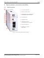
26/99
Device picture, connectors and LEDs
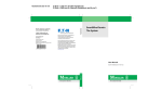
Device picture
(1) 24 V power supply POW
(2) EtherCAT® interface (RJ45)
(3) LEDs EtherCAT® communication status (see subsequent section for details)
(4) MiniUSB interface
(5) Configuration button
(6) LEDs gateway functions
(see subsequent section for details)
(7) 24 V power supply AUX
(8) SmartWireDT connection (plug, 8pole)
Table 12: Front view EU5CSWDETHERCAT gateway
SmartWireDT Gateway | EU5CSWDETHERCAT
DOC140901UM02EN | Revision 2 | English | 201506 | Released | Public
© Hilscher 2015
Device picture, connectors and LEDs
5.2
5.2.1
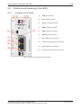
27/99
Positions and meaning of the LEDs
Positions of the LEDs
(1)
POW: System status
(2)
APL: Application status
(3)
Config.: Configuration status
(4)
SWD: SmartWireDT status
(5)
RUN: EtherCAT® bus status
(6)
ERR: EtherCAT® bus error
(7)
L/A: LINK/Activity for channel 0
(8)
Receive/Transmit (RX/TX) for channel 0
(9)
L/A: LINK/Activity for channel 1
(10)
Receive/Transmit (RX/TX) for channel 1
Table 13: LEDs EU5CSWDETHERCAT Gateway
SmartWireDT Gateway | EU5CSWDETHERCAT
DOC140901UM02EN | Revision 2 | English | 201506 | Released | Public
© Hilscher 2015
Device picture, connectors and LEDs
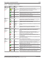
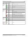
5.2.2
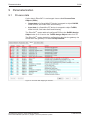
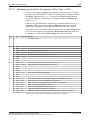
Description of the LEDs
LED
Color
POW System status
Duo LED yellow/green
Number in
picture: (1)
(yellow)
(green/
yellow)
State
On
APL Application
status
Number in
picture: (2)
Backup firmware is active.
The gateway needs a firmware recovery as described in chapter
FirmwareRecovery per HTTP [} page 88].
Blinking green
ROM loader is not able to find bootable image.
The device needs to be sentin for servicing.
Off
Power supply for device is missing or hardware is defect.
Duo LED red/green
On
Communication on EtherCAT® and SmartWireDT is in cyclic data
exchange and the gateway function is executed.
(green)
Blinking
1 s off, 1 s on
Gateway is initialized, but the communication on EtherCAT® or
SmartWireDT is not in cyclic data exchange.
(red)
Blinking
1 s off, 1 s on
Gateway is initialized, but the SmartWireDT configuration is missing
or in error.
On
Gateway has detected an error during the initialization: Missing
configuration, error in configuration or internal error.
(green)
(red)
Config. Configuration
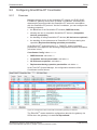
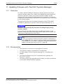
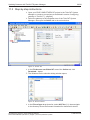
status
Number in
picture: (3)
Duo LED red/green
On
The project configuration complies with the target configuration. Data exchange between gateway and PLC via EtherCAT® is
possible.
Blinking
The project configuration does not comply with the target
configuration, but is compatible with it. Data exchange between
gateway and PLC via EtherCAT® is possible.
On
The project configuration and the target configuration are not
compatible. Data exchange between gateway and PLC via EtherCAT
®
is not possible.
Off
No communication with the EtherCAT® PLC or the gateway does not
have a project configuration.
(green)
(green)
(red)
(off)
SWD SmartWireDT
status
Operating system running, firmware has been started.
On
(green)
(off)
Meaning
Blinking green/ Second Stage Bootloader is not able to load the firmware.
yellow
The device needs to be sentin for servicing.
(green)
Number in
picture: (4)
28/99
Duo LED red/green/orange (orange = red/green at the same time)
On
The actual configuration complies with the target configuration. Data
exchange between gateway and SmartWireDT slaves takes place.
Blinking
The gateway misses its target configuration or a necessary
SmartWireDT slave is missing or the target configuration does not
comply with the actual configuration.
No data exchange between gateway and SmartWireDT slaves.
Blinking
Slave addressing is active (after poweron or download of a project
configuration containing empty modules). No data exchange between gateway and SmartWireDT slaves.
On
Shortcircuit on the 15 V power supply or no SmartWireDT slave is
connected. No data exchange between gateway and SmartWireDT slaves.
Blinking
After having pressed the configuration button: The gateway reads
the actual configuration and stores it as target configuration.
(green)
(red)
(green)
(red)
(orange)
SmartWireDT Gateway | EU5CSWDETHERCAT
DOC140901UM02EN | Revision 2 | English | 201506 | Released | Public
© Hilscher 2015
Device picture, connectors and LEDs
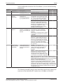
LED
Color
RUN EtherCAT® Bus status
Duo LED red/green
Number in
picture: (5)
State
29/99
Meaning
Off
INIT: The device is in state INIT
Blinking
PREOPERATIONAL: The device is in state PREOPERATIONAL
Single flash
SAFEOPERATIONAL: The device is in state SAFE
OPERATIONAL
On
OPERATIONAL: The device is in state OPERATIONAL
(off)
(green)
(green)
(green)
ERR EtherCAT® Bus error
Duo LED red/green
Off
No error: EtherCAT® communication of the device is in working
condition
Blinking
Invalid Configuration: General Configuration Error (Example: State change commanded by master is impossible due to
register or object settings.)
Single flash
Unsolicited State Change: Slave device application has changed
the EtherCAT® state autonomously: Parameter "Change" in the AL
status register is set to 0x01:change/error (Example:
Synchronization Error, device enters SafeOperational
automatically.)
Double flash
Application Watchdog Timeout: An application watchdog timeout
has occurred. (Example: Sync Manager Watchdog timeout)
On
PDI Watchdog Timeout: A PDI Watchdog timeout has occurred
(Example: Application controller is not responding any more)
L/A (RJ45) Ch0 LED green
& Ch1
On
Link: Gateway has connection to EtherCAT®
Numbers in
pictures: (7) and (9)
Blinking
Activity: Gateway sends/receives EtherCAT® frames
Off
Gateway has no connection to EtherCAT®
Not used
Number in
picture: (6)
(off)
(red)
(red)
(red)
(red)
(green)
(green)
(off)
(RJ45) Ch0 & Ch1
LED yellow
Numbers in
pictures:
(8) and (10)
(yellow)
Table 14: Description of the LEDs
SmartWireDT Gateway | EU5CSWDETHERCAT
DOC140901UM02EN | Revision 2 | English | 201506 | Released | Public
© Hilscher 2015
Device picture, connectors and LEDs
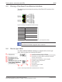
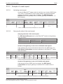
5.3
30/99
Pinning of the RealTime Ethernet interface
The following picture shows the pinning of the EtherCAT interface of the
gateway.
Figure 2: Pinning of the Ethernet interface (RJ45)
Pin
Signal
Description
1
TX +
Transmit Data +
2
TX –
Transmit Data –
3
RX +
Receive Data +
4
TERM
Bob Smith Termination
5
TERM
6
RX –
Receive Data –
7
TERM
Bob Smith Termination
8
TERM
Table 15: Ethernet interface channel 0 and channel 1 pin assignment (RJ45)
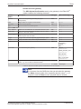
Note:
The Ethernet interface supports auto crossover.
5.4
Device type label
The EU5CSWDETHERCAT Gateway is equipped with a device type
label, which provides the following information:
(1) Version of firmware (at time of delivery)
(2) Information on power supply for switching devices (AUX)
(3) Information on power supply for Gateway and Smart
WireDT slaves (POW)
(4) Information on wire gauge of power supplies
(5) Operating ambient temperature
(6) Device type name
(7) Part number
(8) Hardware revision number
(9) Serial number
Table 16: Device type label EU5CSWDETHERCAT Gateway
SmartWireDT Gateway | EU5CSWDETHERCAT
DOC140901UM02EN | Revision 2 | English | 201506 | Released | Public
© Hilscher 2015
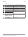
Getting started
6
31/99
Getting started
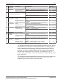
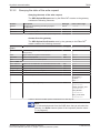
The following table provides an overview of the steps necessary for
installing and commissioning the EU5CSWDETHERCAT Gateway.
#
Step
For details see
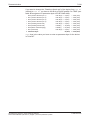
1
Install gateway
Chapter Installing gateway [} page 32]
1.1
Take safety precautions
Section Safety messages [} page 32]
1.2
Mount gateway onto top hat rail
Section Mounting gateway [} page 33]
1.3
Connect gateway to power supply
Section Connecting gateway to power supply [} page 36]
1.4
Connect gateway to SmartWireDT network
Section Connecting SmartWireDT [} page 38]
®
1.5
Connect gateway to EtherCAT network
Section Connecting EtherCAT [} page 39]
2
Configure gateway
Chapter Configuring gateway [} page 41]
2.1
Configure SmartWireDT network in gateway Section Configuring SmartWireDT network in gateway
(creating target configuration) [} page 41]
2.2
Import device description files in EtherCAT® Section Configuring gateway in TwinCAT [} page 44]
engineering tool (TwinCAT System Manager)
2.3
Configure gateway in EtherCAT® engineering
tool
3
Configure SmartWireDT devices in
engineering tool
3.1
Configure SmartWireDT network coordinator Section Configuring SmartWireDT Coordinator [} page 52]
parameters (if other than default settings are used)
3.2
Configure Device Options
(if other than default settings are used)
Section Configuring device options of SmartWireDT devices
in TwinCAT [} page 58]
3.3
Configure Device Parameters
(if other than default settings are used)
Section Configuring device parameters (sensor parameters of
I/O modules) [} page 65]
Section Configuration data of the SWD devices [} page 57]
Table 17: Getting started
SmartWireDT Gateway | EU5CSWDETHERCAT
DOC140901UM02EN | Revision 2 | English | 201506 | Released | Public
© Hilscher 2015
Installing gateway
7
7.1
32/99
Installing gateway
Safety messages
Electrical shock
Please observe the following safety messages when you install and handle
the gateway:
Ø First disconnect the power plug of the device.
Ø Make sure that the power supply is off at the device.
Ø Cover or enclose neighboring units that are live.
Electrostatic Sensitive Device
The gateway is sensitive to electrostatic discharge, which can cause
internal damage and affect its normal operation. Therefore adhere to the
necessary safety precautions for components that are vulnerable to
electrostatic discharge, when you install or handle the gateway:
Ø Do not touch the metal pins of the connectors of the gateway.
Ø Touch a grounded object to discharge potential static.
Ø Wear an approved grounding wrist strap.
Ø If available, use a staticsafe workstation.
Ø When not in use, store the device in an appropriate staticsafe
packaging.
SmartWireDT Gateway | EU5CSWDETHERCAT
DOC140901UM02EN | Revision 2 | English | 201506 | Released | Public
© Hilscher 2015
Installing gateway
7.2
33/99
Mounting gateway
No tools are required for mounting the EU5CSWDETHERCAT Gateway
onto a top hat rail. The back of the gateway (1) carries a springfitted bolt
(2) by which the gateway can be clamped to the rail (3).
Figure 3: Mounting principle of the gateway
7.2.1
Mounting gateway onto top hat rail
To mount the gateway onto the top hat rail, proceed as follows:
Electrical shock: Make sure that the gateway is disconnected
from any power supply! Cover or enclose neighboring units that are live!
Ø Tilt the gateway slightly and hook it into the upper
railing from above, thereby pushing down the
gateway with slight force, in order to overcome the
resistance of the spring in the bolt.
Hook gateway to upper railing
SmartWireDT Gateway | EU5CSWDETHERCAT
DOC140901UM02EN | Revision 2 | English | 201506 | Released | Public
© Hilscher 2015
Installing gateway
34/99
Ø Keep on pushing the gateway downwards and tilt it
back into vertical position, thereby hooking the
gateway into the lower railing.
Hook gateway to lower railing
Ø Let go of the gateway. The spring inside the bolt
automatically pushes the gateway upwards into
the railings, thereby fixing the gateway to the top
hat rail.
Gateway is clamped to top hat rail
SmartWireDT Gateway | EU5CSWDETHERCAT
DOC140901UM02EN | Revision 2 | English | 201506 | Released | Public
© Hilscher 2015
Installing gateway
7.2.2
35/99
Removing gateway from top hat rail
To remove the gateway from the top hat rail, proceed as follows:
Electrical shock: Make sure that the gateway is disconnected
from any power supply! Cover or enclose neighboring units that are live!
Ø Push down the gateway with slight force (to
overcome the resistance of the spring in the bolt),
then unhook the gateway first from the lower railing
and then from the upper railing.
Unhook gateway
SmartWireDT Gateway | EU5CSWDETHERCAT
DOC140901UM02EN | Revision 2 | English | 201506 | Released | Public
© Hilscher 2015
Installing gateway
7.3
36/99
Connecting gateway to power supply
Danger of lethal injuries by unexpected starting up of motors or
machinery!
If you have already integrated devices into a system, secure the operating
range of any connected parts of the system against access, so that nobody
is endangered by motors or machinery starting up unexpectedly.
Danger of unsafe operation of the system
In safetyrelevant applications the power supply providing power for the
SmartWireDT system must feature a PELV power feed module (protective
extra low voltage).
Danger of unsafe operation of the system
You must take safety precautions (emergency switching off) in the external
circuitry of the gateway and any power modules type EU5CSWDPF11 or
EU5CSWDPF21 that are used. To do so, plan to switch off the power
supply to the contactor coils AUX.
Important:
Please take into consideration the total power consumption of your
SmartWireDT network and, if necessary, plan for an additional
feeder module EU5CSWDPF2. You can find information on the
power consumption in the operating manuals of the SmartWireDT
devices.
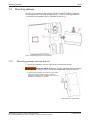
Ø Connect the 24 V DC voltage to the POW terminals on the front side of
the gateway. The POW connection provides the voltage for the gateway
itself and for the SmartWireDT slave electronics.
Note:
For the 15 V supply of the SmartWireDT slaves, the gateway
contains an additional power feed module with an amperage of
0.7 A.
SmartWireDT Gateway | EU5CSWDETHERCAT
DOC140901UM02EN | Revision 2 | English | 201506 | Released | Public
© Hilscher 2015
Installing gateway
37/99
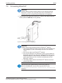
Ø If necessary, connect the 24 V DC voltage for the contactor coils to the
AUX terminals on the front side of the gateway.
Figure 4: Gateway power supply
Note:
The AUX supply is required if any switching devices are also to be
connected, for example, via the DILSWD32001/002 SmartWire
DT slaves. The AUX connection provides the supply for activating
the contactor coils.
This supply must be protected by an automatic circuitbreaker (3A
gG/gl or 3 A miniature circuitbreaker with a Z characteristic).
If switching devices with an activation power greater than 3 A are
connected, an additional feeder module EU5CSWDPF1 or EU5C
SWDPF2 must be used.
Potential conditions between the components
The entire SmartWireDT system operates on a common supply voltage.
Provide a common star point for the earth wiring. In this way, the various
slaves in the SmartWireDT system will not be electrically isolated from one
another. The EtherCAT network and the SmartWireDT system are electrically
isolated from one another.
SmartWireDT Gateway | EU5CSWDETHERCAT
DOC140901UM02EN | Revision 2 | English | 201506 | Released | Public
© Hilscher 2015
Installing gateway
7.4
38/99
Connecting SmartWireDT
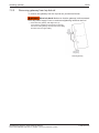
Ø Connect the SmartWireDT network to the gateway. To do so, use the
SmartWireDT cable SWD4100LF824 and the SWD48MF2 relevant
blade terminal or prefabricated cables of type SWD4(3/5/10)F8242S.
Figure 5: Connecting SmartWireDT to gateway
Device destruction
Switch off the power supply before you are reconnecting slaves in the
SmartWireDT system or reconnecting the ribbon cable connection.
Otherwise the SmartWireDT slaves can be destroyed!
Detailed instructions on adapting the SmartWireDT external device
plug (SWD48SF25) to the 8 pole SmartWireDT cable are
provided in chapter Fitting external device plugs SWD48SF25 of
the manual SmartWireDT – The System, MN05006002ZEN
(previously AWB27231617en).
SmartWireDT Gateway | EU5CSWDETHERCAT
DOC140901UM02EN | Revision 2 | English | 201506 | Released | Public
© Hilscher 2015
Installing gateway
7.5
39/99
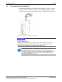
Connecting EtherCAT
Important:
Please note that data exchange between the gateway and the
EtherCAT® network can only take place after a SmartWireDT
network has been connected and configured in the gateway.
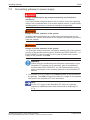
Ø Connect the RJ45 plug of the EtherCAT® cable to the upper Ethernet
socket (labeled LAN1IN) on the gateway.
Figure 6: Connecting EtherCAT to gateway
Important:
Please observe the following notes on EtherCAT® cabling:
Ø Use shielded Ethernet cables that meet the requirements of at
least category 5 (Cat 5) according to EN 50173 or ISO/IEC
11801.
Ø Do not use hubs in an EtherCAT® network.
Ø Do not use switches in a productive system. Use a switch for
diagnostic purpose only and only between EtherCAT® master
and first EtherCAT® slave device (100 MBit/s, Full Duplex). A
switch has influence to the realtime characteristics of the
EtherCAT network.
Ø The cable length between two EtherCAT® devices must not
exceed 100 meter.
See also the user manual Wiring Instructions EtherCAT,
DOC121104UMxxEN, stored on the product DVD in the
Documentation\english\5.Installation Instructions
directory.
SmartWireDT Gateway | EU5CSWDETHERCAT
DOC140901UM02EN | Revision 2 | English | 201506 | Released | Public
© Hilscher 2015
Installing gateway
7.6
40/99
EMCconformant wiring of the network
Undesired faults can occur on the bus due to electromagnetic interference. This can be minimized beforehand by the implementation of suitable EMC
measures. These include:
·
EMCconformant system configuration,
·
EMC compliant cable routing,
·
Measures that do not allow the occurrence of large differences in
potential and
·
correct installation of the EtherCAT system (cables, connection of the
bus connectors, etc.)
The effects of electromagnetic interference can be significantly reduced by
fitting a shield.
For more detailed information on this, please refer to the IAONA
Industrial Ethernet Planning and Installation Guide by IAONA e.V.
Magdeburg, Germany.
SmartWireDT Gateway | EU5CSWDETHERCAT
DOC140901UM02EN | Revision 2 | English | 201506 | Released | Public
© Hilscher 2015
Configuring gateway
8
41/99
Configuring gateway
8.1
Overview
For data exchange between the gateway and the EtherCAT® master, the
gateway needs a valid target configuration and a valid project configuration.
The target configuration of the SmartWireDT network can be created and
stored in the gateway by using the configuration button on the gateway
device. The project configuration must be created and transferred to the
gateway by means of the EtherCAT® engineering tool (i. e. TwinCAT). This chapter describes how to create and store these configurations in the
gateway.
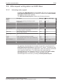
8.2
8.2.1
Configuring SmartWireDT network in gateway (creating
target configuration)
Overview
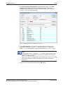
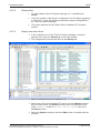
When you commission the gateway, you have to readin the actual
configuration of the SmartWireDT network (i. e. the lineup of the
participants/devices connected to the SWD bus) and store it as target
configuration.
Reading and storing the SmartWireDT network configuration takes place
by pressing the configuration button on the gateway (for the position of the
configuration button, see figure Frontansicht EU5CSWDETHERCAT
Gateway [} page 26]). All SmartWireDT slaves are readdressed in
ascending order by this process.
This process should only take place in the case of:
·
initial commissioning,
·
replacement of a defective slave or
·
deliberate change to the configuration.
Hazard of device damage by disruption of voltage supply while
creating target configuration!
Do not interrupt the voltage supply while creating the target configuration of
the gateway. Power failure during a writing process within the file system
can cause severe malfunctioning of the device.
Important:
If there is a faulty configuration and the configuration button is
pressed, only the slaves up to the failed device are addressed and
stored. Use of the remaining slaves is not possible until the
defective slave has been replaced and the configuration has been
readin again by pressing the configuration button.
SmartWireDT Gateway | EU5CSWDETHERCAT
DOC140901UM02EN | Revision 2 | English | 201506 | Released | Public
© Hilscher 2015
Configuring gateway
42/99
The remanently stored target configuration is compared with the current
configuration (actual configuration) each time the gateway is restarted and
during bus operation. If the gateway recognizes that a required SmartWire
DT slave cannot be reached or a wrong slave type is determined, the
gateway will not go into operation or stops operating. This depends in each
case on the setup of the network which has been defined in the planned/
project configuration. In case of error, the SmartWireDT status LED (SWD
LED) starts to blink in red (for the position of the SWD LED, see section
Positionen der LEDs [} page 27]).
If a SmartWireDT slave has failed, the SmartWireDT network can still be
operated with the remaining slaves, depending on the settings in the
planned/project configuration (even after a repeated power up of the
gateway). The failure is reported to the application.
8.2.2
Prerequisites
Prerequisites for readingin the SmartWireDT configuration are:
8.2.3
·
All SmartWireDT slaves are connected to the SmartWireDT line.
·
The SmartWireDT status LEDs of the individual SmartWireDT slaves
are on or are flashing.
·
The SmartWireDT network is connected to the gateway.
·
The voltage POW is applied to the gateway and the power POW LED is
on.
·
The EtherCAT® network is connected to the gateway and the gateway is
either in INIT or PREOP state (the RUN LED is off or is blinking, see
also section Positions and meaning of the LEDs [} page 27]).
·
The voltage AUX is applied (if necessary).
Stepbystep instructions
To readin the SmartWireDT configuration, proceed as follows:
Ø Press the configuration button on the gateway for at least two seconds
(for the position of the configuration button, see figure in section Device
picture [} page 26]).
Note:
Take care to pushin the button properly. You have to feel and
overcome a slight resistance at the end when pushing the button
into the gateway, otherwise the button will not trigger.
Ê The SmartWireDT status LED (SWD LED) on the gateway begins to
flash orange. The SmartWireDT status LEDs on the SmartWireDT
slaves also flash. All slaves are addressed in sequence, the complete
configuration is stored retentively as gateway target configuration.
SmartWireDT Gateway | EU5CSWDETHERCAT
DOC140901UM02EN | Revision 2 | English | 201506 | Released | Public
© Hilscher 2015
Configuring gateway
43/99
Hazard of device damage by disruption of voltage supply while
creating target configuration!
Do not interrupt the voltage supply while creating the target configuration of
the gateway. Power failure during a writing process within the file system
can cause severe malfunctioning of the device.
Ê The SmartWireDT status LED (SWD LED) on the gateway shows
steady green.
Note:
As an alternative, you can generate and store the target
configuration by using the SWDAssist software. For this, the
gateway must be connected to SWDAssist via USB. For details,
please refer to the SWDAssist online help.
8.3
8.3.1
Configuring gateway in EtherCAT
Device description files
The EU5CSWDETHERCAT Gateway is integrated as slave in the
EtherCAT® network. Configuring the gateway in the EtherCAT® engineering
tool requires two device description files in XML format containing
standardized descriptions of the gateway and the SmartWire devices.
You will find the device description files on the product DVD in the EDS\EU5CSWDETHERCAT\Vx.x.x.x directory. You can also download
the latest versions of the files from our website www.hilscher.com under
Products > Partner Products > SmartWireDT > EU5CSWD
ETHERCAT > Downloads.
Copy the device description files to the relevant directory of your EtherCAT® engineering tool or use the corresponding import function of the
tool. For further information on this, please refer to the documentation of
your engineering tool.
Important:
Please note that data exchange between the gateway and the
EtherCAT® network can only take place after a SmartWireDT
network has been connected and configured in the gateway (see
section Configuring SmartWireDT network in gateway (creating
target configuration) [} page 41]).
SmartWireDT Gateway | EU5CSWDETHERCAT
DOC140901UM02EN | Revision 2 | English | 201506 | Released | Public
© Hilscher 2015
Configuring gateway
8.3.2
44/99
Configuring gateway in TwinCAT
This section describes how to create the project configuration for the
EU5CSWDETHERCAT gateway by using the TwinCAT System Manager
V2.11 on a standard PC. In this example, TwinCAT in combination with the
standard Ethernet network adapter of the PC serve also as Soft PLC and
EtherCAT® master device simultaneously. Please note that commissioning
the gateway in an EtherCAT® network controlled by a “real” hardware PLC
is not subject of this document.
8.3.2.1
8.3.2.2
Prerequisites
·
EU5CSWDETHERCAT gateway
·
The gateway is connected to a SmartWireDT network
·
The gateway contains a valid SmartWireDT configuration (the SWD
LED shows steady green light)
·
PC with installed TwinCAT System Manager and Ethernet adapter
·
The Ethernet adapter of the PC is connected to the gateway via
EtherCAT® network
·
Device description files of the EU5CSWDETHERCAT gateway
Stepbystep instructions
1. Copy device description files into TwinCAT directory.
Ø In the Windows Explorer, open the directory where the device
description files are stored. On the product DVD, this is the EDS\EU5C
SWDETHERCAT\Vx.x.x.x directory.
Ø Copy the device description files.
Note:
You need the Phoenix_EU5CSWD
ETHERCAT_Modules_XXXXXXXX.xml and the Woehner_EU5C
SWDETHERCAT_Modules_XXXXXXXX.xml files only if the Smart
WireDT network includes partner devices by Phoenix or Wöhner.
Ø Copy the files to the TwinCAT\Io\EtherCAT directory of the TwinCAT
installation on your configuration PC.
Ê The device description files of the gateway and the SmartWire devices
are now available in the TwinCAT System Manager.
2. Start TwinCAT.
Ø In the Windows start menu, select All Programs > TwinCAT System >
TwinCAT System Manager.
SmartWireDT Gateway | EU5CSWDETHERCAT
DOC140901UM02EN | Revision 2 | English | 201506 | Released | Public
© Hilscher 2015
Configuring gateway
45/99
Ê The TwinCAT System Manager opens:
Figure 7: TwinCAT start screen
If you already dispose of a project into which you want to integrate the
gateway, open the corresponding project file.
If you haven’t created a project yet, you first have to configure the Ethernet
adapter of your PC as EtherCAT® master device.
3. Configure Ethernet adapter as EtherCAT® master device.
Ø In the Menu, choose Options > Show Real Time Ethernet
Compatible Devices…
Ê The Installation of TwinCAT RTEthernet Adapters dialog window
opens:
Figure 8: Installing TwinCAT Ethernet adapter (1)
SmartWireDT Gateway | EU5CSWDETHERCAT
DOC140901UM02EN | Revision 2 | English | 201506 | Released | Public
© Hilscher 2015
Configuring gateway
46/99
Note:
TwinCAT features two different drivers for Ethernet network
adapters:
The TwinCAT Driver for RealTime Ethernet provides “hard” RTE
support for EtherCAT® applications, but can only be used with Intel
based network adapters. Adapters on your PC recognized by
TwinCAT and supported by this driver are listed under Compatible
devices (see picture above).
The TwinCAT RealTime Ethernet Intermediate Driver can be
used for network adapters without an Intel chip set, but lacks “hard”
RTE support for EtherCAT®. Adapters on your PC recognized by
TwinCAT and supported by this driver are listed under
Incompatible devices.
Ø Select the network adapter which you want to use as TwinCAT master
device, then click Install Button.
Ê After successful installation, the selected network adapter will be
displayed as “TwinCAT Ethernet Adapter” under Installed and ready to
use devices:
Figure 9: Installing TwinCAT Ethernet adapter (2)
Ø Close the dialog window by clicking on the red button in the upper right
corner of the dialog window.
SmartWireDT Gateway | EU5CSWDETHERCAT
DOC140901UM02EN | Revision 2 | English | 201506 | Released | Public
© Hilscher 2015
Configuring gateway
47/99
4. Scan for EtherCAT® devices.
Ø In the navigation tree of the TwinCAT System Manager, select I/O
Devices element, then choose Scan Devices… entry from the context
menu.
Figure 10: Scan devices
Ê A message appears, telling you that not all types of devices can be
found automatically:
Figure 11: Message prior to device scan
Ø Acknowledge with OK.
Ê The New devices found dialog window opens:
Figure 12: New devices found dialog window
SmartWireDT Gateway | EU5CSWDETHERCAT
DOC140901UM02EN | Revision 2 | English | 201506 | Released | Public
© Hilscher 2015
Configuring gateway
48/99
Ø Activate the check box in front of the device which you want to use as
EtherCAT® master device, then click OK.
Ê The New devices found dialog window closes and the selected master
device is inserted in the navigation tree below the I/O Devices element.
Also, the System Manager asks you to Scan for boxes… (i. e.
EtherCAT® slave devices):
Figure 13: Scan for boxes
Ø Start the scanning for boxes process by clicking Yes.
Ê If a “readyforoperation” EU5CSWDETHERCAT gateway has been
properly connected to the EtherCAT® master device (i. e. the
corresponding Ethernet adapter of your PC), the gateway will be found
and displayed as Box [x] (EU5CSWDETHERCAT) below the master
device in the navigation tree. The SmartWire slaves connected to the
gateway will also be found and added to the gateway entry as
subordinate modules. The System Manager asks you to activate the Free Run mode:
Figure 14: EU5CSWDETHERCAT Gateway found as new box
SmartWireDT Gateway | EU5CSWDETHERCAT
DOC140901UM02EN | Revision 2 | English | 201506 | Released | Public
© Hilscher 2015
Configuring gateway
49/99
Ø Activate the Free Run mode by clicking Yes.
Ê In Free Run mode, the TwinCAT configuration data is being transferred
to the gateway. Cyclic data between the EtherCAT® master and the
SmartWire slaves (modules) via the gateway are being exchanged.
5. Testing cyclic data exchange with SmartWire slaves.
Ø In the navigation tree of the TwinCAT System Manager, click on the
plus symbol in front of the gateway element Box [x] (EU5CSWD
ETHERCAT) to expand the tree structure.
Ê The SmartWire slaves connected to the gateway are being displayed in
the navigation tree below the gateway as Module 1, Module 2 etc.:
Figure 15: EU5CSWDETHERCAT Gateway process data (1)
Ø Select the gateway in the navigation tree, then open the Online tab in
the main window.
Ê When Free Run mode is active, the Current State field in the State
Machine area displays OP state (operational). The lower area of the
main window shows the I/O data of the SmartWire slaves.
Ø Create output data at one of the SmartWire slaves. In this example, the
switch of a device connected to the DILSWD32001 slave (Module 1)
is being toggled.
SmartWireDT Gateway | EU5CSWDETHERCAT
DOC140901UM02EN | Revision 2 | English | 201506 | Released | Public
© Hilscher 2015
Configuring gateway
50/99
Ê This event is indicated by a changed value in the Online field of the first
IB0 object in the lower area of the main window:
Figure 16: EU5CSWDETHERCAT Gateway process data (2)
SmartWireDT Gateway | EU5CSWDETHERCAT
DOC140901UM02EN | Revision 2 | English | 201506 | Released | Public
© Hilscher 2015
Parameterization
9
9.1
51/99
Parameterization
Process data
Cyclic data in EtherCAT® is exchanged via socalled Process Data
Objects (PDOs).
·
Output data of a SmartWireDT device is mapped to object RxPDO,
index 0x1600, sub index 0x00 and following.
·
Input data of a SmartWireDT device is mapped to object TxPDO,
index 0x1A00, Sub index 0x00 and following.
The EtherCAT® master adds all configured PDOs to the RxPDO Assign
Object index 0x1C12 and to the TxPDO Assign Object index 0x1C13.
The EtherCAT® master loads this configuration data into the gateway via
SDOs when the gateway is in state PreOperational.
Figure 17: Process data mapping in TwinCAT
SmartWireDT Gateway | EU5CSWDETHERCAT
DOC140901UM02EN | Revision 2 | English | 201506 | Released | Public
© Hilscher 2015
Parameterization
9.2
9.2.1
52/99
Configuring SmartWireDT Coordinator
Overview
Being the master device in the SmartWireDT network, the EU5CSWD
ETHERCAT gateway serves as a socalled “Coordinator” controlling the
data transfer procedure within the SmartWireDT network in accordance
with the SmartWireDT protocol. Via the Coordinator, you can configure the
following properties:
·
the Baud rate of the SmartWireDT network (SWD Baud rate)
·
allowing the use of compatible SmartWireDT devices (Compatible
devices permissible)
·
the handling of failing SmartWireDT devices (All devices are optional)
·
the handling of the replacement of SmartWireDT devices during bus
operation (Replacement during operation permissible)
In the EtherCAT® engineering tool (i. e. TwinCAT), these Coordinator
parameters are mapped to the following configuration elements and indices
(all values in hex):
Coordinator Config: index 0x2100
·
SWD Baud rate: sub index 01
·
Compatible devices permissible: sub index 04
·
All devices are optional: sub index 05
·
Replacement during operation permissible: sub index 08
In the TwinCAT System Manager, the configuration elements of the
Coordinator look as follows:
Figure 18: Configuration data of the SWD Coordinator (gateway) in TwinCAT
The EtherCAT® master loads this configuration data into the gateway via
SDOs when the gateway is in state PreOperational.
SmartWireDT Gateway | EU5CSWDETHERCAT
DOC140901UM02EN | Revision 2 | English | 201506 | Released | Public
© Hilscher 2015
Parameterization
53/99
In the configuration elements of the Coordinator, you can set the following
parameters:
Element
Settings and their meaning
Enter byte value
Index
Parameter
Description
Dez
Hex
0x2100:01
SWD Baud rate
Baud rate of the
SmartWireDT network
125 kBit/s (Default)
125
0x7D
250 kBit/s
250
0xFA
Allows replacement/
substitution of
SmartWireDT devices
by compatible devices
FALSE(0): The devices in the project
0
configuration must comply 100 % with
the devices in the target configuration. If
not, no data interchange takes place
with the EtherCAT® master. (Default)
0x00
TRUE(1): Data exchange with the
1
EtherCAT® master takes place, if the
connected SmartWireDT devices are
different but compatible with the devices
in the project configuration. (This
condition is indicated by the gateway
Config LED blinking green.)
0x01
FALSE(0): You can configure for each 0
SmartWireDT device individually,
whether it is allowed to be missing.
(Default)
(See section Configuring device options
of SmartWireDT devices in TwinCAT [}
page 58])
0x00
TRUE(1): Data exchange with the
1
EtherCAT® master takes place even if
there is a random number of missing
devices in the SmartWireDT network.
The corresponding settings in the device
options of the individual SmartWire
DTdevice slaves thus have no effect and
are overruled.
0x01
FALSE(0) Not allowed; new
SmartWireDT devices must always be
read into the SWD configuration by
pushing the configuration button.
(Default)
0
0x00
TRUE(1) Allows online replacement of 1
SmartWireDT devices during bus
operation without having to push the
configuration button afterwards in order
to read them into the SWD configuration.
0x01
0x2100:04
0x2100:05
0x2100:08
Compatible
devices
permissible
All devices are
optional
Replacement
during operation
permissible
Individual configuration
whether a SmartWireDT
device can be missing is
allowed
Online replacement of
SmartWireDT devices
during bus operation is
allowed
Note: If this parameter is set to TRUE, the All devices are
optional parameter must also be set to TRUE, otherwise the
whole SWD bus will be turned off after losing communication
with one or several SWD devices. Please note also that online replacement during bus
operation is only possible if SWD4FFRPF/ST…. power
supply module/cable adapters are being used. Otherwise
replacement must take place while power is switched off at
the gateway. After return of voltage supply, the network will
automatically be reconfigured (without having to push the
configuration button).
Table 18: Parameter settings of SWD Coordinator
The following exemplary stepbystep instructions show how to change the
baud rate of the SmartWireDT network from 125 kBit/s to 250 kBit/s.
SmartWireDT Gateway | EU5CSWDETHERCAT
DOC140901UM02EN | Revision 2 | English | 201506 | Released | Public
© Hilscher 2015
Parameterization
9.2.2
9.2.3
54/99
Prerequisites
·
PC with installed TwinCAT System Manager V2.11 and Ethernet
adapter
·
You have created a valid project configuration (see Configuring gateway
in TwinCAT [} page 44]) and have opened the project configuration in
the TwinCAT System Manager.
Stepbystep instructions
Ø In the navigation tree of the TwinCAT System Manager, select the
gateway, then open the Startup tab in the main window.
Ê The configuration elements are listed in the Startup tab.
Figure 19: Editing parameters of SWD Coordinator (1)
Ø Search the list for the configuration element of the Coordinator
parameter that you want to edit. A Coordinator parameter can be
recognized by the index 0x2100:XX and the Coordinator Config:
[Parameter] entry in the Comment column.
Ø For this example, select the element marked with the index 0x2100:01
and the Comment entry Coordinator Config: SWD Baud rate
(125/250 kBaud/s), then click Edit button (or doubleclick the
element).
SmartWireDT Gateway | EU5CSWDETHERCAT
DOC140901UM02EN | Revision 2 | English | 201506 | Released | Public
© Hilscher 2015
Parameterization
55/99
Ê The Edit CANopen Startup Entry dialog window opens. The Data
(hexbin) field displays the preset hexadecimal value of the byte
configuring this parameter. In case of the baud rate, this is the value 7D
00 (the 00 byte is a reserved byte):
Figure 20: Editing parameters of SWD Coordinator (2)
Ø In the Data (hexbin) field, enter the new hexadecimal value of the
parameter. Omit the 0x prefix; i. e. enter the value 0xFA simply as
string FA. You can delete the reserved second byte (i. e. the 00 byte).
Note:
Entering the value FA (decimal = 250) in this example causes the
Coordinator (i. e. the gateway) to run the SmartWireDT network
with a 250 kBaud/s rate.
What value has to be entered for other parameters is shown in table
Parameter settings of SWD Coordinator in section Overview [}
page 52].
Ø Take over the new value by clicking the OK button.
SmartWireDT Gateway | EU5CSWDETHERCAT
DOC140901UM02EN | Revision 2 | English | 201506 | Released | Public
© Hilscher 2015
Parameterization
56/99
Ê The Data column of the Startup tab displays the changed value (the
corresponding decimal value is displayed in brackets behind the
hexadecimal value).
Figure 21: Editing parameters of SWD Coordinator (3)
Ø In the main menu of the TwinCAT System Manager, choose Actions >
Activate Configuration… to download the changed configuration data.
SmartWireDT Gateway | EU5CSWDETHERCAT
DOC140901UM02EN | Revision 2 | English | 201506 | Released | Public
© Hilscher 2015
Parameterization
9.3
9.3.1
57/99
Configuration data of the SWD devices
Overview
Besides information on process data, the ESI files of the SmartWireDT
device also contain devicespecific information like module ID (Product
code), configuration data (CFG), device options (Options) and additional
device parameters (Parameters). When a SmartWireDT device (i. e. a module) is added to the project
configuration, the EtherCAT® engineering tool (i. e. TwinCAT) maps these
data sets to the following elements (all values in hex):
Device (Module) 1: index 0x8000
·
Module ID (Product code): sub index 06
·
Configuration data (CFG): sub index 20
·
Device options (Options): sub index 21
·
Device parameters (Parameters): sub index 22
Device (Module) 2: index 0x8010
·
Module ID (Product code): sub index 06
·
Configuration data (CFG): sub index 20
·
Device options (Options): sub index 21
·
Device parameters (Parameters): sub index 22
etc...
In the TwinCAT System Manager, the configuration elements of the SWD
devices DILSWD32001 and PKESWD32 Profile 2 for instance look as
follows:
Figure 22: Configuration data elements of SWD devices in TwinCAT
SmartWireDT Gateway | EU5CSWDETHERCAT
DOC140901UM02EN | Revision 2 | English | 201506 | Released | Public
© Hilscher 2015
Parameterization
58/99
The EtherCAT® master loads this configuration data into the gateway via
SDOs when the gateway is in state PreOperational. Also, the device parameters (Parameters) of sub index 22 are loaded into
the corresponding SmartWireDT device, if the device is an I/O module (the
purpose of the device parameters is to configure the sensors of I/O
modules).
The module ID (Product code) of sub index 06 and the configuration data (
CFG) of sub index 20 are needed by the gateway for identification and
configuration purposes and must not be changed. The device options (
Options) of sub index 21 and the device parameters (Parameters) of sub
index 22 on the other hand can be edited if necessary. This is described in
the following sections.
9.3.2
9.3.2.1
Configuring device options of SmartWireDT devices in TwinCAT
Overview
Each SWD device carries an element for configuring certain device options
in TwinCAT. With this Options element (sub index 21), you can determine
for each device individually, whether its presence in the SmartWireDT
network is mandatory or whether it may be substituted by an M22SWD
NOP universal module.
The preset defaults for all devices are:
·
Presence in SmartWireDT network: device must be present
·
Replacement/substitution by universal module: not allowed
Note:
If you reconfigure the “presence option” of an individual device in
order to allow it to be missing in the SmartWireDT network, this
option will only be effective if the All Modules Optional (index
0x2100:08) parameter of the Coordinator is being kept at its
default 0x00 setting. This allows you to configure the “presence
option” for each device individually in its device options element.
See also section Configuring SmartWireDT Coordinator [} page 52
].
The parameters of the Options element (i. e. the device options) are
configured by entering a single hexadecimal options byte.
Please note that this byte does not only define the two options mentioned
above (i. e. presence in the SWD network and replacement by universal
module), but also defines other parameters like e. g. payload formats. The
presets of these other parameters may vary from device to device and must
not be changed by the user. Each parameter is represented by a single bit in the options byte, each bit
set TRUE has an individual byte value. The assignment of parameters to
bits and their byte values are shown in the subsequent table:
SmartWireDT Gateway | EU5CSWDETHERCAT
DOC140901UM02EN | Revision 2 | English | 201506 | Released | Public
© Hilscher 2015
Parameterization
Bit
0
1
2
3
4
59/99
Parameter
(function)
Description
Parameter
(Device)
Extended parameters
TRUE(1): Device has extended parameters
Important: Do not
change this parameter!
Presence
(Coordinator)
CRC8
(Coordinator)
Motorola
(Coordinator)
Replacement
Configuration
Byte value
Dez
Hex
0
0x00
1
0x01
Presence in SmartWire FALSE(0): Device may be absent in current SWD
DT network
bus configuration
0
0x00
TRUE(1): Device must be present in current SWD
bus configuration (default)
2
0x02
FALSE(0): Device sends its cyclic input data without 0
CRC8
0x00
TRUE(1): Device sends its cyclic input data followed 4
Important: Do not
change this parameter! by CRC8
0x04
Format of payload data FALSE(0): Device codes/decodes payload data
words
words in its own littleendian format
0
0x00
TRUE(1): Device codes/decodes payload data words 8
Important: Do not
change this parameter! in bigendian format
0x08
Substitution by
universal module
Cyclic input data with
CRC8
FALSE(0): Device has no extended parameters
FALSE(0): Replacement of device by universal
module is not allowed (default)
0
0x00
TRUE(1): Device can be replaced by universal
module
16
0x10
5
Reserved
Bit is not used (0)
0
0x00
6
Profile
(Device)
Support of data profiles FALSE(0): Device does not have different data
profiles
Important: Do not
0
0x00
7
AcycService
(Device)
change this parameter! TRUE(1): Device supports different data profiles and 64
requires the Coordinator to set the profile accordingly
0x40
Support of acyclic data
requests
0
0x00
128
0x80
FALSE(0): Device does not have acyclic data
objects
TRUE(1): Device supports acyclic read/write
Important: Do not
change this parameter! requests from Coordinator
Table 19: Bit assignment of parameters of options byte
The logically ORed byte values of the individual bits amount to the value of
the options byte. To change an individual parameter, you have to look at
the bit representing this parameter. After having set the bit on TRUE in
order to activate the corresponding parameter (respectively the desired
function), you have to logically OR the new byte value of the changed bit
with the byte values of the other TRUE bits. For examples of how to
perform such a calculation, see section Examples of calculating the options
byte [} page 62].
The following exemplary stepbystep instructions show how to change the
default options of the DILSWD32001 device, in order to allow the
replacement of the device by a universal module.
SmartWireDT Gateway | EU5CSWDETHERCAT
DOC140901UM02EN | Revision 2 | English | 201506 | Released | Public
© Hilscher 2015
Parameterization
9.3.2.2
9.3.2.3
60/99
Prerequisites
·
PC with installed TwinCAT System Manager V2.11 and Ethernet
adapter
·
You have created a valid project configuration (see Configuring gateway
in TwinCAT [} page 44]) and have opened the project configuration in
the TwinCAT System Manager
·
The project features the DILSWD32001 SmartWireDT contactor
module
Stepbystep instructions
Ø In the navigation tree of the TwinCAT System Manager, select the
gateway, then open the Startup tab in the main window.
Ê The configuration elements are listed in the Startup tab:
Figure 23: Editing device options of SWD device (1)
Ø Search the list for the SmartWireDT device and the Options element
that you want to edit. An Options element can be recognized by the
index 0x8XXX:21 and the Options [device name] entry in the
Comment column.
Ø Select the Options element, then click Edit button (or doubleclick the
element).
SmartWireDT Gateway | EU5CSWDETHERCAT
DOC140901UM02EN | Revision 2 | English | 201506 | Released | Public
© Hilscher 2015
Parameterization
61/99
Ê The Edit CANopen Startup Entry dialog window opens. The Data
(hexbin) field displays the preset hexadecimal value of the options byte.
In case of the DILSWD32001 device, this is the value 02:
Figure 24: Editing device options of SWD device (2)
Ø Enter the new hexadecimal value of the options byte into the Data
(hexbin) field. Omit the 0x prefix; i. e. enter the value 0x12 simply as
string 12.
Note:
Individual parameters of the Options element (i. e. the device
options) can only be configured by entering a single hexadecimal
options byte. For changing one or several parameters, you
therefore have to recalculate the whole options byte of the device.
The outcome of this calculation depends on the parameter bits you
have changed and on the default settings of the device.
Entering the value 12 in this example means that the device may in
future be replaced by a universal module in the SmartWireDT
network.
For examples of how to calculate the options byte, see section
Examples of calculating the options byte [} page 62].
Ø Take over the new value by clicking the OK button.
SmartWireDT Gateway | EU5CSWDETHERCAT
DOC140901UM02EN | Revision 2 | English | 201506 | Released | Public
© Hilscher 2015
Parameterization
62/99
Ê The Data column of the Startup tab displays the changed hexadecimal
value of the options byte (the corresponding decimal value is displayed
in brackets).
Figure 25: Editing device options of SWD device (3)
Ø In the main menu of the TwinCAT System Manager, choose Actions >
Activate Configuration… to download the changed configuration data.
9.3.2.4
Examples of calculating the options byte
Individual parameters of the Options element (i. e. the device options) can
only be configured by entering a single hexadecimal options byte. The logically ORed byte values of the individual bits representing the
configuration parameters amount to the value of the options byte. To change an individual parameter, you have to look at the bit representing
this parameter. After having set the bit on TRUE in order to activate the
corresponding parameter (respectively the desired function), you have to
“logically OR” (i. e. “add up”) the new byte value of the changed bit with the
byte values of the other TRUE bits. Please note that each active bit (i. e.
each bit set TRUE) has a different byte value. The assignment of
parameters to bits and their byte values are shown in table Bit assignment
of parameters of options byte in section Overview [} page 58]. Because all
bits set to FALSE have the byte value 0, you can ignore all FALSE bits in
the addition.
SmartWireDT Gateway | EU5CSWDETHERCAT
DOC140901UM02EN | Revision 2 | English | 201506 | Released | Public
© Hilscher 2015
Parameterization
63/99
Example 1
This example shows how to calculate the default value 0x02 of the options
byte of the DILSWD32001 SWD device. The 02 value of the options byte results from the fact that all bits except Bit
1 have been set to FALSE, thus all having the byte value 0; Bit 1 on the
other hand has been set to TRUE, thus having the byte value 02, which
after logical ORing amounts to the value 0x02 for the whole options byte:
Bit 0 (Extended parameters)
= FALSE(0) = 0 (Dez) =
0x00 (Hex)
+
Bit 1 (Presence in SmartWireDT network)
= TRUE(1)
= 2 (Dez) =
0x02 (Hex)
+
Bit 2 (Cyclic input data with CRC8)
= FALSE(0) = 0 (Dez) =
0x00 (Hex)
+
Bit 3 (Format of payload data words)
= FALSE(0) = 0 (Dez) =
0x00 (Hex)
+
Bit 4 (Substitution by universal module)
= FALSE(0) = 0 (Dez) =
0x00 (Hex)
+
Bit 5 (reserved)
= FALSE(0) = 0 (Dez) =
0x00 (Hex)
+
Bit 6 (Support of data profiles)
= FALSE(0) = 0 (Dez) =
0x00 (Hex)
+
Bit 7 (Unterstützung azyklischer Dienste)
= FALSE(0) = 0 (Dez) =
0x00 (Hex)
=
Options Byte
2 (Dez) =
0x02 (Hex)
This options byte means for the DILSWD32001 device that it must be
present in the current bus configuration (Bit 1 = TRUE), but that is has no
extended parameters (Bit 0 = FALSE) and does not use CRC8 with its
cyclic input data (Bit 2 = FALSE) etc.
If you now want to allow the substitution of the device within the SmartWire
DT bus by an universal module, you have to set Bit 4 to TRUE and then
add the newly created byte value (in this case 16 [Dez] respectively
0x10 [Hex]) to the other byte values in order to calculate options byte:
Bit 0 (Extended parameters)
= FALSE(0) = 0 (Dez)
= 0x00 (Hex)
+
Bit 1 (Presence in SmartWireDT network)
= TRUE(1)
= 2 (Dez)
= 0x02 (Hex)
+
Bit 2 (Cyclic input data with CRC8)
= FALSE(0) = 0 (Dez)
= 0x00 (Hex)
+
Bit 3 (Format of payload data words)
= FALSE(0) = 0 (Dez)
= 0x00 (Hex)
+
Bit 4 (Substitution by universal module)
= TRUE(1)
+
Bit 5 (reserved)
= FALSE(0) = 0 (Dez)
= 0x00 (Hex)
+
Bit 6 (Support of data profiles)
= FALSE(0) = 0 (Dez)
= 0x00 (Hex)
+
Bit 7 (Support of acyclic data requests)
= FALSE(0) = 0 (Dez)
= 0x00 (Hex)
=
Options Byte
= 16 (Dez) = 0x10 (Hex)
18 (Dez) = 0x12 (Hex)
0x12 thus is the value you have to enter as options byte for the device in
TwinCAT, in case you want to allow its replacement by universal module.
Example 2
This example shows how to calculate the default value 0xC2 of the options
byte of the PKESWD32Profile 2 SWD device:
Bit 0 (Extended parameters)
= FALSE(0) = 0 (Dez)
= 0x00 (Hex)
+
Bit 1 (Presence in SmartWireDT network)
= TRUE(1)
= 2 (Dez)
= 0x02 (Hex)
+
Bit 2 (Cyclic input data with CRC8)
= FALSE(0) = 0 (Dez)
= 0x00 (Hex)
+
Bit 3 (Format of payload data words)
= FALSE(0) = 0 (Dez)
= 0x00 (Hex)
+
Bit 4 (Substitution by universal module)
= FALSE(0) = 0 (Dez)
= 0x00 (Hex)
+
Bit 5 (reserved)
= FALSE(0) = 0 (Dez)
= 0x00 (Hex)
+
Bit 6 (Support of data profiles)
= TRUE(1)
= 64 (Dez)
= 0x40 (Hex)
+
Bit 7 (Support of acyclic data requests)
= TRUE(1)
= 128 (Dez) = 0x80 (Hex)
=
Options Byte
SmartWireDT Gateway | EU5CSWDETHERCAT
DOC140901UM02EN | Revision 2 | English | 201506 | Released | Public
194 (Dez) = 0xC2 (Hex)
© Hilscher 2015
Parameterization
64/99
If you now want to allow the device to be missing within the SmartWireDT
bus and also that it may be replaced by an universal module, you have to
set Bit 1 to FALSE and Bit 4 to TRUE. The calculation for this looks as
follows:
Bit 0 (Extended parameters)
= FALSE(0) = 0 (Dez)
= 0x00 (Hex)
+
Bit 1 (Presence in SmartWireDT network)
= FALSE(0) = 0 (Dez)
= 0x00 (Hex)
+
Bit 2 (Cyclic input data with CRC8)
= FALSE(0) = 0 (Dez)
= 0x00 (Hex)
+
Bit 3 (Format of payload data words)
= FALSE(0) = 0 (Dez)
= 0x00 (Hex)
+
Bit 4 (Substitution by universal module)
= TRUE(1)
= 0x10 (Hex)
+
Bit 5 (reserved)
= FALSE(0) = 0 (Dez)
= 0x00 (Hex)
+
Bit 6 (Support of data profiles)
= TRUE(1)
= 64 (Dez)
= 0x40 (Hex)
+
Bit 7 (Support of acyclic data requests)
= TRUE(1)
= 128 (Dez) = 0x80 (Hex)
=
Options Byte
= 16 (Dez)
208 (Dez) = 0xD0 (Hex)
0xD0 thus is the value you have to enter as options byte for the device in
TwinCAT.
Hint:
The Windows calculator (if configured accordingly) can be used to display
the corresponding bit values of a hexadecimal byte value. Thus you can
check, which of the bits are being set to FALSE (0) and which of the bits
are being set to TRUE (1) when you enter a certain byte value:
Figure 26: “Programmer” view of Windows 7 calculator
SmartWireDT Gateway | EU5CSWDETHERCAT
DOC140901UM02EN | Revision 2 | English | 201506 | Released | Public
© Hilscher 2015
Parameterization
9.3.3
9.3.3.1
65/99
Configuring device parameters (sensor parameters of I/O modules)
Overview
For some SmartWireDT devices, individual device parameters can be
configured.
Configurable parameters of the SmartWireDT devices are
described in the manual SmartWireDT Modules, Doc ID
MN05006001ZEN, which is stored on the product DVD in the
directory Documentation\english\3.SmartWireDT
\SmartWireDT – Units\MN05006001Z_EN.pdf
This section describes how to configure sensor type, refresh rate and
averaging of the inputs/outputs modules EU5ESWD4AX, EU5E
SWD2A2A and EU5ESWD4PT by editing their Parameters element (sub
index 22) in TwinCAT.
Please note that this section is of exemplary nature. You always have to
look up the definite bit assignment of the parameter byte of individual
devices in the latest documentation of the device’s manufacturer.
The subsequent tables show the bit assignments of the Parameters bytes
of the SmartWireDT devices EU5ESWD4AX, EU5ESWD2A2A and
EU5ESWD4PT:
EU5ESWD4AX
Bit
Parameter
(function)
Configuration
Sensor selector
Input 1
1
2
0
3
4 5
Byte value
Dez
Hex
FALSE(0): Voltage (default)
0
0x00
TRUE(1): Current
1
0x01
Sensor selector
Input 2
FALSE(0): Voltage (default)
0
0x00
TRUE(1): Current
2
0x02
Sensor selector
Input 3
FALSE(0): Voltage (default)
0
0x00
TRUE(1): Current
4
0x04
Sensor selector
Input 4
FALSE(0): Voltage (default)
0
0x00
TRUE(1): Current
8
0x08
Reading refresh rate Bit 5
Bit 4
Milli
seconds
FALSE(0)
FALSE(0)
20 ms
0
0x00
FALSE(0)
TRUE(1)
100 ms
(default)
16
0x10
TRUE(1)
FALSE(0)
200 ms
32
0x20
TRUE(1)
TRUE(1)
500 ms
48
0x30
6
Mean value
(averaging)
FALSE(0): off
0
0x00
TRUE(1): on (default)
64
0x40
7
Reserved
FALSE(0)
0
0x00
Table 20: Bit assignment of parameter byte of EU5ESWD4AX
SmartWireDT Gateway | EU5CSWDETHERCAT
DOC140901UM02EN | Revision 2 | English | 201506 | Released | Public
© Hilscher 2015
Parameterization
66/99
EU5ESWD2A2A
Bit
Parameter
(function)
Configuration
Dez
Hex
0
Sensor selector
Input 1
FALSE(0): Voltage (default)
0
0x00
TRUE(1): Current
1
0x01
1
Sensor selector
Input 2
FALSE(0): Voltage (default)
0
0x00
TRUE(1): Current
2
0x02
Actuator selector
Output 1
FALSE(0): Voltage (default)
0
0x00
TRUE(1): Current
4
0x04
3
Actuator selector
Output 2
FALSE(0): Voltage (default)
0
0x00
8
0x08
4 5
Reading refresh rate Bit 5
2
6
7
Byte value
TRUE(1): Current
Bit 4
Milli
seconds
FALSE(0)
FALSE(0)
20 ms
0
0x00
FALSE(0)
TRUE(1)
100 ms
(default)
16
0x10
TRUE(1)
FALSE(0)
200 ms
32
0x20
TRUE(1)
TRUE(1)
500 ms
48
0x30
Mean value
(averaging)
FALSE(0): off
0
0x00
TRUE(1): on (default)
64
0x40
Reserved
FALSE(0)
0
0x00
Table 21: Bit assignment of parameter byte of EU5ESWD2A2A
EU5ESWD4PT
Byte 1:
Bit
0 1
2 3
4 5
6 7
Parameter
(function)
Configuration
Sensor
selection Input 1
Bit 1
Bit 0
Sensor type
FALSE(0)
FALSE(0)
FALSE(0)
TRUE(1)
Sensor
selection Input 2
Sensor
selection Input 3
Sensor
selection Input 4
Byte value
Dez
Hex
Not used (default)
0
0x00
TRUE(1)
PT100
1
0x01
FALSE(0)
PT1000
2
0x02
TRUE(1)
TRUE(1)
NI1000
3
0x03
Bit 3
Bit 2
Sensor type
FALSE(0)
FALSE(0)
Not used (default)
0
0x00
FALSE(0)
TRUE(1)
PT100
4
0x04
TRUE(1)
FALSE(0)
PT1000
8
0x08
TRUE(1)
TRUE(1)
NI1000
12
0x0C
Bit 5
Bit 4
Sensor type
FALSE(0)
FALSE(0)
Not used (default)
0
0x00
FALSE(0)
TRUE(1)
PT100
16
0x10
TRUE(1)
FALSE(0)
PT1000
32
0x20
TRUE(1)
TRUE(1)
NI1000
48
0x30
Bit 7
Bit 6
Sensor type
FALSE(0)
FALSE(0)
Not used (default)
0
0x00
FALSE(0)
TRUE(1)
PT100
64
0x40
TRUE(1)
FALSE(0)
PT1000
128
0x80
TRUE(1)
TRUE(1)
NI1000
192
0xC0
Table 22: Bit assignment of parameter byte 1 of EU5ESWD4PT
SmartWireDT Gateway | EU5CSWDETHERCAT
DOC140901UM02EN | Revision 2 | English | 201506 | Released | Public
© Hilscher 2015
Parameterization
67/99
Byte 2:
Bit
Parameter
(function)
Configuration
0 1
Measurement
display
Bit 1
Bit 0
Unit
FALSE(0)
FALSE(0)
FALSE(0)
TRUE(1)
2 3
Byte value
Dez
Hex
Degrees Celsius
(default)
0
0x00
TRUE(1)
Degrees Fahrenheit
1
0x01
FALSE(0)
Binary value
2
0x02
Bit 2
Rate
FALSE(0)
0.25 s (default)
0
0x00
FALSE(0)
TRUE(1)
1 s
4
0x04
TRUE(1)
FALSE(0)
2.5 s
8
0x08
TRUE(1)
TRUE(1)
10 s
12
0x0C
Reading refresh Bit 3
rate
FALSE(0)
4
Reserved
FALSE(0)
0
0x00
5
Reserved
FALSE(0)
0
0x00
6
Reserved
FALSE(0)
0
0x00
7
Reserved
FALSE(0)
0
0x00
Table 23: Bit assignment of parameter byte 2 of EU5ESWD4PT
The following exemplary stepbystep instructions show how to change the
parameter “Reading refresh rate” of the EU5ESWD4AX device from 100
ms (default) to 200 ms.
9.3.3.2
Prerequisites
·
PC with installed TwinCAT System Manager V2.11 and Ethernet
adapter
·
You have created a valid project configuration (see section Configuring
gateway in TwinCAT [} page 44]) and have opened the project
configuration in the TwinCAT System Manager
·
The project features the EU5ESWD4AX SmartWireDT I/O module
SmartWireDT Gateway | EU5CSWDETHERCAT
DOC140901UM02EN | Revision 2 | English | 201506 | Released | Public
© Hilscher 2015
Parameterization
9.3.3.3
68/99
Stepbystep instructions
Ø In the navigation tree of the TwinCAT System Manager, select the
gateway, then open the Startup tab in the main window.
Ê The configuration elements are listed in the Startup tab.
Figure 27: Editing device parameters of SWD device (1)
Ø Search the list for the SmartWireDT device and the Parameters
element that you want to edit. An Parameters element can be
recognized by the index 0x8XXX:22 and the Parameters [device
name] entry in the Comment column.
Ø Select the Parameters element, then click Edit button (or doubleclick
the element).
SmartWireDT Gateway | EU5CSWDETHERCAT
DOC140901UM02EN | Revision 2 | English | 201506 | Released | Public
© Hilscher 2015
Parameterization
69/99
Ê The Edit CANopen Startup Entry dialog window opens. The Data
(hexbin) field displays the preset hexadecimal value of the parameter
byte. In case of the EU5ESWD4AX device, this is the value 02 50:
Figure 28: Editing device parameters of SWD device (2)
Important:
Please note that the first byte in the Data (hexbin) field (in this
example 02) is the “length byte” denoting the total number of bytes
contained in the Parameters element. This first length byte must not
be changed. In case of the devices EU5ESWD4AX and EU5ESWD2A2A, the
Parameters element consists of two bytes of which you are allowed
to change only the second byte. In case of the EU5ESWD4PT
device, the Parameters element consists of three bytes of which
you are allowed to change only the last two bytes.
Ø In the Data (hexbin) field, change the value of the second byte. Omit
the 0x prefix; i. e. enter the value 0x60 simply as string 60.
Note:
The Parameters can only be configured by entering hexadecimal
byte values. For changing the parameters, you therefore have to
recalculate a new byte value. The outcome of this calculation
depends on the parameter bits you are changing and on the default
settings of the device. Entering the value 60 in this example
changes the “Reading refresh rate” of the device from 100 ms
(default) to 200 ms.
For an example of how to calculate the parameters byte, see
section Example of calculating the parameters byte [} page 70].
SmartWireDT Gateway | EU5CSWDETHERCAT
DOC140901UM02EN | Revision 2 | English | 201506 | Released | Public
© Hilscher 2015
Parameterization
70/99
Ø Take over the new value by clicking the OK button.
Ê The Data column of the Startup tab displays the changed hexadecimal
value of the parameters byte (the corresponding decimal value is
displayed in brackets).
Figure 29: Editing device parameters of SWD device (3)
Ø In the main menu of the TwinCAT System Manager, choose Actions >
Activate Configuration… to download the changed configuration data.
9.3.3.4
Example of calculating the parameters byte
This example shows how to calculate the default value 0x50 of the
parameter byte of the EU5ESWD4AX SWD device:
Bit 0 (Sensor selector input 1)
= FALSE(0) = 0 (Dez)
= 0x00 (Hex)
+
Bit 1 (Sensor selector input 2)
= FALSE(0) = 0 (Dez)
= 0x00 (Hex)
+
Bit 2 (Sensor selector input 3)
= FALSE(0) = 0 (Dez)
= 0x00 (Hex)
+
Bit 3 (Sensor selector input 4)
= FALSE(0) = 0 (Dez)
= 0x00 (Hex)
+
Bit 4 (Reading refresh rate)
= TRUE(1)
= 0x10 (Hex)
+
Bit 5 (Reading refresh rate)
= FALSE(0) = 0 (Dez)
= 0x00 (Hex)
+
Bit 6 (Mean value/averaging)
= TRUE(1)
= 0x40 (Hex)
+
Bit 7 (Reserved)
= FALSE(0) = 0 (Dez)
=
Parameter Byte
SmartWireDT Gateway | EU5CSWDETHERCAT
DOC140901UM02EN | Revision 2 | English | 201506 | Released | Public
= 16 (Dez)
= 64 (Dez)
80 (Dez)
= 0x00 (Hex)
= 0x50 (Hex)
© Hilscher 2015
Parameterization
71/99
If you want to change the “Reading refresh rate” of the device from 100 ms
(default) to 200 ms, you have to set Bit 4 to FALSE and Bit 5 to TRUE (see
table Bit assignment of parameter byte of EU5ESWD4AX):
Bit 0 (Sensor selector input 1)
= FALSE(0) = 0 (Dez)
= 0x00 (Hex)
+
Bit 1 (Sensor selector input 2)
= FALSE(0) = 0 (Dez)
= 0x00 (Hex)
+
Bit 2 (Sensor selector input 3)
= FALSE(0) = 0 (Dez)
= 0x00 (Hex)
+
Bit 3 (Sensor selector input 4)
= FALSE(0) = 0 (Dez)
= 0x00 (Hex)
+
Bit 4 (Reading refresh rate)
= FALSE(0) = 0 (Dez)
= 0x00 (Hex)
+
Bit 5 (Reading refresh rate)
= TRUE(1)
= 32 (Dez)
= 0x20 (Hex)
+
Bit 6 (Mean value/averaging)
= TRUE(1)
= 64 (Dez)
= 0x40 (Hex)
+
Bit 7 (Reserved)
= FALSE(0) = 0 (Dez)
=
Parameter Byte
96 (Dez)
= 0x00 (Hex)
= 0x60 (Hex)
0x60 thus is the value you have to enter as parameter byte for the device
in TwinCAT.
SmartWireDT Gateway | EU5CSWDETHERCAT
DOC140901UM02EN | Revision 2 | English | 201506 | Released | Public
© Hilscher 2015
Acyclical communication
72/99
10 Acyclical communication
10.1 Overview
The EtherCAT® master exchanges acyclic data with individual SmartWire
DT slaves via gateway by using the index 0x2200, sub index 1 object and
the index 0x2200, sub index 2 object.
The subsequent section describes a typical acyclic communication process
(see also diagram on the following page):
1. The EtherCAT® master sends a task (read or write request) for a
SmartWireDT slave to the index 0x2200, sub index 1 object by using
an SDO Download Request. The gateway acknowledges the reception
of the task by sending back an SDO Download Confirmation.
2. The gateway forwards the task to the SWD slave. The SWD slave
executes the requested read or write task in the specified SWD Index.
3. While the gateway is waiting for an answer from the SWD slave, the
EtherCAT® master regularily queries the state of the task by sending
SDO Upload Requests to the index 0x2200, sub index 2 object. As
long as the gateway has not yet received the answer from the SWD
slave (SmartWire DT communication is slower than EtherCAT®
communication) the SDO Upload Confirmation conveys the Request
State 1 (= „in progress“). The EtherCAT® master thus has to keep on sending SDO Upload
Requests to the gateway.
4. The answer from the SWD slave arrives in the gateway, where it is
stored in the index 0x2200, sub index 2 object. In case the task has
been successfully executed, the Request State is set to 2 (= „finished“).
5. On the next SDO Upload Request, the newly arrived answering data
from the SWD slave is being sent from the gateway to the EtherCAT®
master in the SDO Upload Confirmation. In case of a read request, it
contains the data which was read from the SWD Index of the SWD
slave. The Request State and the Error Code, which are also
contained in the SDO Upload Confirmation, indicate to the master
whether the task has been finished successfully or if an error occurred.
SmartWireDT Gateway | EU5CSWDETHERCAT
DOC140901UM02EN | Revision 2 | English | 201506 | Released | Public
© Hilscher 2015
Acyclical communication
73/99
Figure 30: Conducting acyclical communication
SmartWireDT Gateway | EU5CSWDETHERCAT
DOC140901UM02EN | Revision 2 | English | 201506 | Released | Public
© Hilscher 2015
Acyclical communication
74/99
10.2 Read request: reading data of an SWD Slave
10.2.1
Activating read request
A reading task (Read Request) for a SmartWireDT slave is conveyed in
an SDO Download Request from the EtherCAT® master to the index
0x2200, sub index 1 object in the gateway. The SDO Download Request contains the following elements:
Element
Description
Data type
Value / value range
Address
Node ID of the gateway (according to project configuration)
uint16
0…65535
Index
Object index for acyclical communication
uint16
0x2200
Sub index
Index for SDO Download
uint8
0x01
Size
Amount of data of the SDO Download
10 Bytes
Slave Address
Address of the SWD slave that you want to read (according
to project configuration)
uint8
1…99
SWD Index
SWDspecific index of the SWD slave. Determines which
uint8
kind of data you want to read, e. g. error counter or firmware
version.
0…255
Request Type
Type of request. A read request must have the value 1
1
Length
Maximum length of the expected response in bytes. Must be uint8
at least as long as the SWD object (in bytes).
1…120
Job ID
Freely selectable value, serves as job identification
uint8
0…255
Reserved Bytes
Five reserved bytes
uint8[5]
0x00, 0x00,
0x00, 0x00, 0x00
Header
Data for SWD slave
uint8
Table 24: Elements SDO Download of a read request
The gateway acknowledges the reception of the task by sending back an
SDO Download Confirmation to the EtherCAT® master. The gateway also
forwards the task to the SWD slave, where the reading task is performed in
the specified SWD Index. The SWD slave then sends back the answer to
the gateway, where it is stored in the index 0x2200, sub index 2 object.
The EtherCAT® master can then fetch the answer by sending an SDO
Upload Request.
10.2.2
Querying the state of the read request
Querying the state of the read request
The SDO Upload Request sent by the EtherCAT® master to the gateway
contains the following elements:
Element
Description
Data type
Value / value range
Address
Node ID of the gateway (according to project
configuration)
uint16
0…65535
Index
Object index for acyclical communication
uint16
0x2200
Sub index
Index for SDO Upload
uint8
0x02
Table 25: Elements of SDO Upload Request for a read request
SmartWireDT Gateway | EU5CSWDETHERCAT
DOC140901UM02EN | Revision 2 | English | 201506 | Released | Public
© Hilscher 2015
Acyclical communication
75/99
Answer from the gateway
The SDO Upload Confirmation sent by the gateway to the EtherCAT®
master contains the following elements:
Element
Description
Data type
Value / value range
Address
Node ID of the gateway (according to project
configuration)
uint16
0…65535
Index
Object index for acyclical communication
uint16
0x2200
Sub index
Index for SDO Upload
uint8
0x02
Size
Amount of data of the SDO Upload
10 Bytes + n *
Header
Data of SWD slave
Slave Address
Address of the SWD slave of which data has been read.
uint8
1…99
SWD Index
SWD index of the data which has been read, e. g. error
counter or firmware version.
uint8
0…255
Request Type
Type of request. A read request has the value 1
uint8
0x01
Length
Length of the received response (payload data) in bytes
uint8
1…120
Job ID
Freely selectable value, serves as job identification
uint8
0…255
State
State of the response
uint8
Idle = 0
In Progress = 1
Finished = 2
Error = 3
Error Code
Error detected by the gateway
uint32
No error = 0x00000000
JOBID_BUFFER_FULL
= 0xC0AD0002
JOB_DENIED
= 0xC0AD0003
NOT_AVAILABLE
= 0xC0AD0004
Data
Payload data which has been read according to SWD
Index, e. g. error counter or firmware version.
uint8 [n1] *
(…)
* n = amount of read bytes
Table 26: Elements of SDO Upload Confirmation for a read request
Note:
If no answer from the SWD slave has yet arrived at the gateway,
the State element (state of the response) has the value 1 (= „in
progress“) and the Data element (payload data) is omitted.
SmartWireDT Gateway | EU5CSWDETHERCAT
DOC140901UM02EN | Revision 2 | English | 201506 | Released | Public
© Hilscher 2015
Acyclical communication
10.2.3
10.2.3.1
76/99
Example of a read request
Activating read request
In case the EtherCAT® master wants to read the error counter (SWD Index
127) of the 5th SmartWireDT slave (slave address 5), and the expected
response should be no longer than 120 Bytes, the SDO Download
Request sent to the gateway looks as follows (gateway has Node ID 3 in
this example):
Syntax
Header
Data
Address
Object
index
Sub index Size
Slave
Address
SWD
Index
Request
Type
Length
Job ID
Reserved Bytes
0x03
0x2200
0x01
0x05
0x7F
0x01
0x78
0x01
0x00, 0x00,
0x00, 0x00,
0x00
0xA
Table 27: Example SDO Download Request for a read request
10.2.3.2
Querying the state of the read request
Querying the state of the read request
The SDO Upload Request sent by the EtherCAT® master to the gateway
looks as follows:
Syntax
Address
Object index
Sub index
0x03
0x2200
0x02
Table 28: Example SDO Upload Request for a read request
Answer of the gateway in case of an unfinished read request
If the gateway has not yet received the answer from the SWD slave, the
SDO Upload Confirmation sent by the gateway to the EtherCAT® master
looks as follows:
Syntax
Header
Data
Address
Object
index
Sub
index
Size
Slave
Address
SWD
Index
Request
Type
Length
Job ID
State
Error Code
0x03
0x2200
0x02
0xA
0x05
0x7F
0x01
0x00
0x01
0x01
0x00000000
Table 29: Example SDO Upload Confirmation for an unfinished read request
Answer of the gateway in case of a finished read request
If the answer from the SWD slave has arrived, the SDO Upload
Confirmation sent by the gateway to the EtherCAT® master looks as
follows:
Syntax
Header
Data
Address
Object
index
Sub
index
Size
Slave
Address
SWD
Index
Request
Type
Length
Job ID
State
Error
Code
Data
0x03
0x2200
0x02
0x82
0x05
0x7F
0x01
0x78
0x01
0x02
0x0000 (…)
0000
Table 30: Example SDO Upload Confirmation for a finished read request
SmartWireDT Gateway | EU5CSWDETHERCAT
DOC140901UM02EN | Revision 2 | English | 201506 | Released | Public
© Hilscher 2015
Acyclical communication
77/99
10.3 Write request: writing data in an SWD Slave
10.3.1
Activating write request
A writing task (Write Request) for a SmartWireDT slave is conveyed in an
SDO Download Request from the EtherCAT® master to the index 0x2200,
sub index 1 object in the gateway. The SDO Download Request contains the following elements:
Element
Description
Data type
Value / value range
Address
Node ID of the gateway (according to project
configuration)
uint16
0…65535
Index
Object index for acyclical communication
uint16
0x2200
Sub index
Index for SDO Download
uint8
0x01
Size
Amount of data of the SDO Download
10 Bytes + n *
Slave Address
Address of the SWD slave that you want to read
(according to project configuration)
uint8
1…99
SWD Index
SWDspecific index of the SWD slave. Determines
where to write the data to.
uint8
0…255
Request Type
Type of request. A write request must have the value
2
uint8
2
Length
Length of the data (in bytes) to be written.
uint8
1…120
Job ID
Freely selectable value, serves as job identification
uint8
0…255
Reserved Bytes
Five reserved bytes
uint8[5]
0x00, 0x00, 0x00,
0x00, 0x00
Data
Data to be written (payload data)
uint8[n1] *
(...)
Header
Data for SWD slave
* n = amount of bytes to be written
Table 31: Elements SDO Download of a write request
The gateway acknowledges the reception of the task by sending back an
SDO Download Confirmation to the EtherCAT® master. The gateway also
forwards the write request to the SWD slave, where the writing is performed
in the specified SWD Index. The SWD slave then sends back an
acknowledgement to the gateway, where it is stored in the index 0x2200,
sub index 2 object. The EtherCAT® master can then fetch the
acknowledgement from there by sending an SDO Upload Request.
SmartWireDT Gateway | EU5CSWDETHERCAT
DOC140901UM02EN | Revision 2 | English | 201506 | Released | Public
© Hilscher 2015
Acyclical communication
10.3.2
78/99
Querying the state of the write request
Querying the state of the write request
The SDO Upload Request sent by the EtherCAT® master to the gateway
contains the following elements:
Element
Description
Data type
Value / value range
Address
Node ID of the gateway (according to project
configuration)
uint16
0…65535
Index
Object index for acyclical communication
uint16
0x2200
Sub index
Index for SDO Upload
uint8
0x02
Table 32: Elements of SDO Upload Request for a write request
Answer from the gateway
The SDO Upload Confirmation sent by the gateway to the EtherCAT®
master contains the following elements:
Element
Description
Data type
Value / value range
Address
Node ID of the gateway (according to project
configuration)
uint16
0…65535
Index
Object index for acyclical communication
uint16
0x2200
Sub index
Index for SDO Upload
uint8
0x02
Size
Amount of data of the SDO Upload
10 Bytes
Header
Data of SWD slave
Slave Address
Address of the SWD slave of which data has been read.
uint8
1…99
SWD Index
SWD index into which the data was written
uint8
0…255
Request Type
Type of request. A write request has the value 2
uint8
0x02
Length
Length of the written data in bytes
uint8
1…120
Job ID
Freely selectable value, serves as job identification
uint8
0…255
State
State of the response
uint8
Idle = 0
In Progress = 1
Finished = 2
Error = 3
Error Code
Error detected by the gateway
uint32
No error = 0x00000000
JOBID_BUFFER_FULL
= 0xC0AD0002
JOB_DENIED
= 0xC0AD0003
NOT_AVAILABLE
= 0xC0AD0004
Table 33: Elements of SDO Upload Confirmation for a write request
Note:
If no acknowledgement from the SWD slave has yet arrived at the
gateway, the State element (state of the response) has the value 1
(= „in progress“).
SmartWireDT Gateway | EU5CSWDETHERCAT
DOC140901UM02EN | Revision 2 | English | 201506 | Released | Public
© Hilscher 2015
Acyclical communication
10.3.3
10.3.3.1
79/99
Example of a write request
Activating read request
In case the EtherCAT® master wants to reset the error counter (SWD Index
127) of the 5th SmartWireDT slave (slave address 5) to zero (i. e. Data =
0), the SDO Download Request sent to the gateway looks as follows
(gateway has Node ID 3 in this example):
Syntax
Header
Data
Address
Object
index
Sub
index
Size
Slave
Address
SWD
Index
Request
Type
Length
Job ID
Reserved Bytes Data
0x03
0x2200
0x01
0xB
0x05
0x7F
0x02
0x01
0x01
0x00, 0x00,
0x00,
0x00,0x00
0x00
Table 34: Example SDO Download Request for a write request
10.3.3.2
Querying the state of the write request
Querying the state of the write request
The SDO Upload Request sent by the EtherCAT® master to the gateway
looks as follows:
Syntax
Address
Object index
Sub index
0x03
0x2200
0x02
Table 35: Example SDO Upload Request for a write request
Answer of the gateway in case of an unfinished write request
If the gateway has not yet received the acknowledgement from the SWD
slave, the SDO Upload Confirmation sent by the gateway to the
EtherCAT® master looks as follows:
Syntax
Header
Data
Address
Object
index
Sub
index
Size
Slave
Address
SWD
Index
Request
Type
Length
Job ID
State
Error Code
0x03
0x2200
0x02
0xA
0x05
0x7F
0x02
0x01
0x01
0x01
0x00000000
Table 36: Example SDO Upload Confirmation for an unfinished write request
Answer of the gateway in case of a finished write request
If the acknowledgement from the SWD slave has arrived, the SDO Upload
Confirmation sent by the gateway to the EtherCAT® master looks as
follows:
Syntax
Header
Auftragsdaten
Address
Object
index
Sub
index
Size
Slave
Address
SWD
Index
Request
Type
Length
Job ID
State
Error Code
0x03
0x2200
0x02
0xA
0x05
0x7F
0x02
0x01
0x01
0x02
0x00000000
Table 37: Example SDO Upload Confirmation for a finished write request
SmartWireDT Gateway | EU5CSWDETHERCAT
DOC140901UM02EN | Revision 2 | English | 201506 | Released | Public
© Hilscher 2015
Acyclical communication
80/99
10.4 Emergency telegrams: Error and status messages (diagnosis)
10.4.1
Overview
The gateway reports changes concerning the state of the gateway or the
state of the SmartWireDT network by means of an Emergency Telegram.
Errors occurring in individual SWD slaves are also reported to the
EtherCAT master by the gateway by means of an Emergency Telegram. In
cases of messages concerning the state of the gateway or the SWD
network, the Emergency Telegram generated by the gateway begins with
the Entry Type (byte 0) = 0xFF. In cases of error messages concerning
individual SWD slaves, the Emergency Telegram begins with the Entry
Type (byte 0) = 0x70. Resolved errors are also reported by the gateway to
the EtherCAT master by means of an Emergency Telegram. For these
“error reset” messages, the telegram starts with the Entry Type (byte 0) =
0x00.
The gateway stores each error message in its message buffer, from where
it is deleted only after the corresponding error has been resolved (Error
Reset). Whether further error messages still exist in the error buffer or not,
is signaled to the EtherCAT master in each Emergency Telegram by a flag
in Bit 0 of the Error Type (Byte 2) field.
An EmergencyTelegram consists of eight bytes and has the following
structure:
Error Code
Error Register
Additional Information
Entry Type
Address
Error Type
Diagnosis Code
Error Flags
Byte 0
Byte 1
Byte 2
Byte 3
Byte 4
May contain one
of the following
three message
types:
ID of the
concerned
device:
The first bit (bit 0)
indicates whether
the message
buffer still contains
error or status
messages:
In case of Entry Type (Byte
0) = 0x70 (error of individual
SWD slave), this byte
features a diagnostic code
specifying the nature of the
error. For details see section
Error messages (diagnosis)
of individual SWD slaves
(Entry Type = 0x70) [} page
81]
In case of Entry Type (Byte 0)
= 0xFF (SWD network error/
status change message issued
by the gateway), these bytes
feature error flags specifying
the nature of the error/status
change. For details see section
Messages generated by the
gateway (Entry Type = 0xFF) [}
page 83].
In case of Entry Type (Byte
0) = 0xFF (SWD network
error/status change message
issued by the gateway), this
byte is not used (= 0x00).
The nature of the SWD
network error/status message
is then specified in the Error
Flags (bytes 4 to 7), not in
the diagnosis code.
In case of Entry Type (Byte 0)
= 0x70 (error of individual
SWD slave), these bytes are
not used (= 0x00).
0xFF
message
generated by the
gateway about
SWD errors or
status changes.
0x70
error of an
individual SWD
slave.
0x00
resolved error
(error reset).
0x00
Gateway
(SWD master)
0x01... 0x63
SWD slave
Bit 0 = 0
no further
messages
Bit 0 = 1
buffer contains at
least one more
message
Note: Bit 1 to 7
are reserved.
Byte 5 Byte 6 Byte 7
In case of Entry Type (byte 0)
= 0x00 (resolved error/error
reset), these bytes specify the
nature of the SWD network
error that has been resolved.
In case of an Entry Type
(byte 0) = 0x00(resolved
error/error reset), this byte
specifies the error of the
individual slave that has been
resolved.
Table 38: Structure of Emergency Telegram
SmartWireDT Gateway | EU5CSWDETHERCAT
DOC140901UM02EN | Revision 2 | English | 201506 | Released | Public
© Hilscher 2015
Acyclical communication
10.4.2
81/99
Error messages (diagnosis) of individual SWD slaves (Entry Type =
0x70)
In case of error/diagnosis messages issued by individual SmartWireDT
devices, the Emergency Telegram which the gateway sends to the
EtherCAT master always begins with Entry Type (byte 0) = 0x70, thus
signaling to the EtherCAT master the occurrence a newly detected
("incoming") error/diagnosis from an individual SmartWireDT device. In
cases of messages about resolved errors (error reset), the Emergency
Telegram begins with Entry Type (byte 0) = 0x00.
The SWD device reporting the error can be the gateway itself (in its role as
SWD master) or one of the 99 SWD slave devices. The ID of the concerned
SWD device is indicated in the Address field (byte 1) of the Emergency
Telegram. The address value 0x00 represents the gateway itself, values
0x01 to 0x63 represent the consecutively numbered SWD slaves from
device 1 to device 99.
The nature of the error is indicated in the Diagnosis Code field (byte 3) of
the Emergency Telegram (the Error Flag fields [bytes 4 to 7] are not used
here). Note that the diagnostic codes are defined by the manufacturers of
the individual SWD devices and can therefore differ from device to device.
For the EU5CSWDETHERCAT gateway, there is currently only one code
defined:
Diagnosis Code Meaning
0xF3
Project configuration does not
comply with target configuration.
Used by
EU5CSWDETHERCAT gateway
Table 39: Diagnosis Code of gateway
The diagnosis codes of individual SmartWireDT slaves can be lookedup
in the user manual of the corresponding device (for devices manufactured
by Eaton, for example, this would be the manual SmartWireDT modules,
MN05006001ZEN). The subsequent table provides some examples of
diagnostic codes of SmartWireDT slave devices:
Diagnosis Code Meaning
Used by
0x00
No diagnostic message active
All devices that support the extended
diagnosis
0x10
Contact in middle position
RMQ
0x11
Contact shortcircuit
RMQ
0x13
Output overload
I/O module
Table 40: Examples of diagnostic codes of SWD slaves
SmartWireDT Gateway | EU5CSWDETHERCAT
DOC140901UM02EN | Revision 2 | English | 201506 | Released | Public
© Hilscher 2015
Acyclical communication
82/99
Example: Emergency Telegram for new ("incoming") error/diagnosis
of SWD device
If an I/O module placed on position 5 within the SmartWireDT network (i. e.
Address = 0x05) detects an output overload, (i. e. Diagnosis Code =
0x13), the telegram looks as follows:
Error Code
Error Register
Additional Information
Entry Type Address Error Type
Byte 0
Byte 1
Byte 2
Bit 0
Diagnosis
Code
Error Flags
Byte 3
Byte 4 Byte 5 Byte 6 Byte 7
reserved
Bit 1 Bit 2 Bit 3 Bit 4 Bit 5 Bit 6 Bit 7
0x70
0x05
1
0/1 0/1
0/1 0/1 0/1 0/1
0/1 0x13
0x00
0x00
0x00
0x00
Table 41: Emergency Telegram for new ("incoming") error/diagnosis of SWD device
Example: Emergency Telegram for resolved error/diagnosis of an
SWD device (Error Reset)
If the same I/O module reports that the output is not overloaded any longer
(output overload error has been reset), and there are no further error/
diagnosis messages stored in the message buffer of the gateway, the
telegram looks as follows:
Error Code
Error Register
Additional Information
Entry Type Address Error Type
Byte 0
Byte 1
Byte 2
Bit 0
Diagnosis
Code
Error Flags
Byte 3
Byte 4 Byte 5 Byte 6 Byte 7
reserved
Bit 1 Bit 2 Bit 3 Bit 4 Bit 5 Bit 6 Bit 7
0x00
0x05
0
0/1 0/1
0/1 0/1 0/1 0/1
0/1 0x13
0x00
0x00
0x00
0x00
Table 42: Emergency Telegram in case of a resolved error
Note:
If an error has been resolved, but the message buffer of the
gateway is still holding at least one further unresolved error/
diagnosis issue, the gateway indicates the fact that there still are
pending error issues by setting bit 0 of the Error Type field (byte 2)
= 1.
SmartWireDT Gateway | EU5CSWDETHERCAT
DOC140901UM02EN | Revision 2 | English | 201506 | Released | Public
© Hilscher 2015
Acyclical communication
10.4.3
83/99
Messages generated by the gateway (Entry Type = 0xFF)
In case of messages issued by the gateway concerning errors or status
changes of the SmartWireDT network, the Emergency Telegram begins
with Entry Type (byte 0) = 0xFF. In case of messages about resolved
errors (Error Reset), the Emergency Telegram begins with Entry Type
(byte 0) = 0x00.
If the error on the SWD bus is related to an individual SWD slave (e. g. a
mandatory SWD device is missing), the Address field (byte 1) of the
Emergency Telegram indicates the ID of the concerned slave device.
The nature of the error/status change is specified in the Error Flags (bytes
4 to 7) of the Emergency Telegram (the Diagnosis Code field [byte 3] is
not used here). The following Error Flags are currently defined:
Byte
Hex
Relevance Meaning
4
Currently not used
5
0
0x01
1
0x02
2
0x04
Info
SWD: Checking project configuration
3
0x08
4
0x10
Info
SWD: Extended diagnosis of a device is present
5
0x20
6
0x40
7
0x80
0
0x01
Error
SWD: Mandatory SmartWireDT device is missing
1
0x02
Warning
SWD: Optional SmartWireDT device is missing
2
0x04
3
0x08
4
0x10
5
0x20
Error
SWD: No valid project configuration
6
0x40
7
0x80
0
0x01
Error
SWD: Short circuit in the 15V voltage supply of the SmartWireDT bus
1
0x02
Error
SWD: Internal error of the SmartWireDT coordinator
2
0x04
Info
SWD: At least one SmartWireDT device sends basic diagnosis
3
0x08
Error
SWD: No SmartWireDT device detected
4
0x10
Info
SWD: Using compatible devices is allowed
5
0x20
Info
SWD: All devices are registered as „optional“
6
0x40
Info
SWD: Comparison of project configuration with target configuration disabled
7
0x80
6
7
Table 43: Error Flags in case of messages generated by the gateway
SmartWireDT Gateway | EU5CSWDETHERCAT
DOC140901UM02EN | Revision 2 | English | 201506 | Released | Public
© Hilscher 2015
Acyclical communication
84/99
Example: Emergency Telegram for new ("incoming") error/diagnosis
of SWD bus
If a mandatory SmartWireDT slave (in this example slave device No. 5) is
missing, the Emergency Telegram reporting this bus error looks as follows:
Error Code
Error Register
Additional Information
Entry Type Address Error Type
Diagnosis
Code
Error Flags
Byte 0
Byte 3
Byte 4 Byte 5 Byte 6 Byte 7
Byte 1
Byte 2
Bit 0
reserved
Bit 1 Bit 2 Bit 3 Bit 4 Bit 5 Bit 6 Bit 7
0xFF
0x05
1
0/1 0/1
0/1 0/1 0/1 0/1
0/1 0x00
0x00
0x00
0x01
0x00
Table 44: Emergency Telegram for incoming error on SWD bus
Example: Emergency Telegram for resolved SWD bus error (Error
Reset)
If the gateway reports, that the mandatory SmartWireDT slave is not
missing any longer (i. e. device has returned on the bus), and there are no
further error/diagnosis messages stored in the message buffer of the
gateway, the telegram looks as follows:
Error Code
Error Register
Additional Information
Entry Type Address Error Type
Byte 0
Byte 1
Byte 2
Bit 0
Diagnosis
Code
Error Flags
Byte 3
Byte 4 Byte 5 Byte 6 Byte 7
reserved
Bit 1 Bit 2 Bit 3 Bit 4 Bit 5 Bit 6 Bit 7
0x00
0x05
0
0/1 0/1
0/1 0/1 0/1 0/1
0/1 0x00
0x00
0x00
0x01
0x00
Table 45: Emergency Telegram in case of resolved SWD bus error
Note:
If an error has been resolved, but the message buffer of the
gateway is still holding at least one other unresolved error/diagnosis
issue, the gateway indicates this in the telegram by setting Bit 0 of
the Error Type field (byte 2) = 1.
SmartWireDT Gateway | EU5CSWDETHERCAT
DOC140901UM02EN | Revision 2 | English | 201506 | Released | Public
© Hilscher 2015
Updating firmware with TwinCAT System Manager
85/99
11 Updating firmware with TwinCAT System Manager
11.1 Overview
The EU5CSWDETHERCAT Gateway is shipped with its most recent
firmware already loaded. The version of the loaded firmware is stated on
the device type label. When you perform a firmware update, the old
firmware file in the gateway will automatically be overwritten. The project
configuration and the target configuration in the gateway remain untouched
by the firmware update.
This section describes how to update the firmware of the EU5CSWD
ETHERCAT gateways by using the TwinCAT System Manager V2.11.
Hazard of device damage by disruption of voltage supply during
firmware update!
Do not interrupt the voltage supply while updating the firmware of the
gateway. Power failure during a writing process within the file system can
cause severe malfunctioning of the device.
Note:
In case of a missing or defective firmware (which is indicated by a
green POW LED), the “regular” firmware update process described
in this chapter is not working. In this case, proceed as described in
chapter Firmware recovery via HTTP [} page 88].
11.2 Prerequisites
·
The gateway is connected to a SmartWireDT network
·
The gateway contains a SmartWireDT configuration
·
PC with installed TwinCAT System Manager V2.11 and Ethernet
adapter
·
The Ethernet adapter of the PC is connected to the gateway via
EtherCAT® network
·
You have access to the new firmware file which you want to download
to the EU5CSWDETHERCAT gateway
SmartWireDT Gateway | EU5CSWDETHERCAT
DOC140901UM02EN | Revision 2 | English | 201506 | Released | Public
© Hilscher 2015
Updating firmware with TwinCAT System Manager
86/99
11.3 Stepbystep instructions
Ø Open your EU5CSWDETHERCAT project in the TwinCAT System
Manager or create a new project as described in section Configuring
gateway in TwinCAT [} page 44].
Ø Select the gateway in the navigation tree of the TwinCAT System
Manager, then open the Online tab in the main window.
Figure 31: “Online” tab
Ø In the File Access over EtherCAT area of the Online tab, click
Download... button.
Ê The Windows file the selection dialog window opens:
Figure 32: Select Firmware
Ø In the Files of type dropdown list, select All Files (*.*), then navigate
to the directory where the firmware intended for download is stored.
SmartWireDT Gateway | EU5CSWDETHERCAT
DOC140901UM02EN | Revision 2 | English | 201506 | Released | Public
© Hilscher 2015
Updating firmware with TwinCAT System Manager
87/99
Ø Select E030F0U0.nxf file, then click Open button.
Ê The Edit FoE Name dialog window opens:
Figure 33: Edit firmware name (1)
Ø In the String field, add the file name extension .nxf
Important:
You must enter the file name extension .nxf here, otherwise the
gateway will not accept the file (“nxf” stands for “netX firmware”).
Take care to also enter the dot between name and extension !
Figure 34: Edit firmware name (2)
Ø Click OK button.
Ê The download of the firmware is started. The download process can
take several minutes. The progress of the download is indicated by a
progress bar in the footer of the TwinCAT System Manager.
Hazard of device damage by disruption of voltage supply during
firmware update!
Do not interrupt the voltage supply while downloading the firmware of the
gateway. Power failure during a writing process within the file system can
cause severe malfunctioning of the device.
Ø Wait until the download has been completed, then reset the gateway (i.
e. briefly disconnect the gateway from the voltage supply) in order to
start the new firmware.
SmartWireDT Gateway | EU5CSWDETHERCAT
DOC140901UM02EN | Revision 2 | English | 201506 | Released | Public
© Hilscher 2015
Firmware recovery via HTTP
88/99
12 Firmware recovery via HTTP
12.1 Overview
If the POW system status LED of the gateway shows steady green light,
the “regular” firmware of the gateway is defective or missing (for the
position of the POW LED see section Positions of the LEDs [} page 27]).
In this case only the socalled “backup firmware” is running and the device
is not able to perform its normal gateway functions. This state can be
resolved by downloading a fresh (i. e. uncorrupted) firmware file into the
gateway via HTTP protocol. The backup firmware (which is part of the boot
strap loader running in the gateway) carries a “web server” functionality for
downloading a firmware file comfortably via its Ethernet interface.
For this, you just have to connect the gateway via its Ethernet interface to
an active DHCP server and a configuration PC. The purpose of the DHCP
server is to assign an IP address to the gateway. This assigned IP address
can then be used by the configuration PC to connect to the download
function of the backup firmware running in the gateway, in order to
download the new firmware file via ordinary web browser. If you do not know the exact IP address assigned to the gateway by the
DHCP server, you can use the Hilscher Ethernet Device Configuration
Tool on your configuration PC (included on the product DVD) in order to
“read out” the newly assigned IP address from the gateway. (The tool uses
the netIDENT protocol to search for all Hilscher devices within the
connected IP network, and then lists all found devices and their IP
addresses.)
Note:
This chapter describes only how to download the recovery firmware.
Instructions on how to configure and operate a DHCP server are not
subject of this manual. For information on using a DHCP server,
please consult your local network administrator.
12.2 Prerequisites
·
The gateway is supplied with voltage and the backup firmware inside
the device is running (this is indicated by steady green light at the POW
LED)
·
The gateway is disconnected from the EtherCAT® network
·
The gateway is connected to an active DHCP server via local Ethernet
network
·
The gateway is connected via local Ethernet network to a configuration
PC with installed standard web browser
·
You have access to the firmware file which you want to download to the
gateway (the firmware file is stored on the SmartWireDT Gateway
Solutions product DVD in the Firmware\EU5CSWDETHERCAT
\Vx.x.x.x folder).
SmartWireDT Gateway | EU5CSWDETHERCAT
DOC140901UM02EN | Revision 2 | English | 201506 | Released | Public
© Hilscher 2015
Firmware recovery via HTTP
·
89/99
You know the IP address, which the DHCP server has assigned to the
gateway. If not, install the Hilscher Ethernet Device Configuration
Tool on your configuration PC. This tool allows you to check the current
IP address of the gateway (if the configuration PC and the gateway are
connected to the same local Ethernet network). An installer for this
program can be found on the product DVD in the Software
\EnDeviceCfg folder (the program can also be installed by using the
menu of the product DVD.)
12.3 Stepbystep instructions
1. Use DHCP server to assign IP address to gateway.
Ø Disconnect the gateway from the voltage supply.
Ø Plug a cable connected to the local Ethernet network (in which a DHCP
server is active) into one of the Ethernet RJ45 sockets (labeled LAN1
IN or LAN2OUT) on the front side of the gateway.
Ø Reconnect the gateway to the voltage supply.
Note:
The L/A LINK/Activity LEDs of the Ethernet RJ45 sockets remain
dark when an Ethernet cable is pluggedin while the backup
firmware is running – even if a successful IP communication with an
local Ethernet network has been established.
Ê The backup firmware running in the device now sends a socalled
DHCPDISCOVER message broadcast into the Ethernet network,
requesting an IP address from a DHCP server. If a DHCP service is
available in the network, the gateway should be receiving a valid IP
address from the server within a few seconds.
2. Check IP address.
Ø In the Windows Start menu of your configuration PC, select All
Programs > Hilscher GmbH > Ethernet Device Configuration, to
start the Ethernet Device Configuration Tool.
Ê The Ethernet Device Configuration tool opens:
Figure 35: Ethernet Device Configuration Tool
Ø Click Search Devices button, to start searching for the gateway within
the local Ethernet network.
SmartWireDT Gateway | EU5CSWDETHERCAT
DOC140901UM02EN | Revision 2 | English | 201506 | Released | Public
© Hilscher 2015
Firmware recovery via HTTP
90/99
Ê The tool starts scanning for devices and lists all found Hilscher devices
and their IP addresses:
Figure 36: Found gateway in Ethernet Device Configuration Tool
Ø Note or write down the IP address.
Note:
If the default IP address 0.0.0.0 is displayed, the gateway has not
yet received an IP address from a DHCP server. Make sure that the
gateway is connected to a subnet with an active DHCP server.
Then restart the gateway by briefly disconnecting the voltage supply
while the Ethernet cable remains pluggedin. Wait a few seconds
after reconnecting the voltage supply, then click the Search
Devices button in the Ethernet Device Configuration Tool again.
3. Open web page for firmware download.
Ø Start the web browser on your configuration PC.
Ø In the address bar of your browser, enter the IP address of the gateway:
http://<IP address>
SmartWireDT Gateway | EU5CSWDETHERCAT
DOC140901UM02EN | Revision 2 | English | 201506 | Released | Public
© Hilscher 2015
Firmware recovery via HTTP
91/99
Ê The Firmware Update page opens:
Figure 37: Firmware recovery via HTTP (as depicted in Internet Explorer)
4. Select firmware file for download.
Ø Click Browse… button, to open a dialog window for selecting the
firmware file you want to download.
Ø Navigate to the directory in which the firmware file is stored, select the
file, then click Open.
Note:
The name of the firmware file for the EU5CSWDETHERCAT
gateway is E030F0U0.nxf
Ê Path and name of the selected file are displayed in the field next to the
Browse… button.
5. Download firmware file to gateway.
Ø Click Transfer button to download the new firmware file to the gateway.
SmartWireDT Gateway | EU5CSWDETHERCAT
DOC140901UM02EN | Revision 2 | English | 201506 | Released | Public
© Hilscher 2015
Firmware recovery via HTTP
92/99
Ê After you have started the download by clicking the Transfer button, the
validity of the firmware file is being checked by the system. If the file
fails the validity check, an error message will be displayed. If the file
passes, the gateway requests you to perform a reset in order to start
the new firmware:
Figure 38: Reset after firmware download via HTTP (as depicted in Internet Explorer)
6. Perform reset.
Ø Activate the checkbox in front of Please confirm… to acknowledge that
you want to reset the gateway.
Note:
You can use the Cancel button to uncheck the checkbox in front of
Please confirm...
Ø Click Submit button to start the reset.
Ê After successful reset, the following message is displayed:
Figure 39: Successful device reset message (as depicted in Internet Explorer)
ð The POW system status LED at the gateway shows steady yellow light.
The new firmware has been loaded and the gateway is ready for
operation.
SmartWireDT Gateway | EU5CSWDETHERCAT
DOC140901UM02EN | Revision 2 | English | 201506 | Released | Public
© Hilscher 2015
Technical data
93/99
13 Technical data
13.1 Technical data EU5CSWDETHERCAT gateway
Category
Parameter
Value
General
Part number
9233.922
Dimensions (W x H x D)
35 x 90 x 127 mm
Weight
160 g
Mounting
Top hat rail 35 mm (IEC/EN 60715)
Mounting position
Vertical
Standards
IEC/EN 611312
Communication controller
netX 50 processor
Configuration and diagnostic interface MiniUSB
Ambient mechanical
conditions
Integrated memory
8 MB SDRAM
4 MB serial Flash EPROM
Protection type (IEC/EN 60529, EN50178, VBG 4)
IP20
Vibrations (IEC/EN 611312:2008)
Constant amplitude 3.5 mm: 5 – 9 Hz
Constant acceleration 1 g: 9 – 150 Hz
Mechanical shock resistance (IEC/EN 60068227)
Semisinusoidal 15 g/11 ms: 9 Shocks
Drop to (IEC/EN 60068231)
Drop height: 50 mm
Free fall, packaged (IEC/EN 60068232)
Drop height: 1 m
Ambient climatic conditions Operating ambient temperature (IEC 600682)
Electromagnetic
compatibility (EMC)
25…+55 °C
Condensation
Prevent by suitable measures
Storage
40…+70 °C
Relative humidity, noncondensing
(IEC/EN 60068230)
5…95 %
Pollution degree
2
Electrostatic discharge (IEC/EN 611312:2008)
Air discharge (Level 3): 8 kV
Contact discharge (Level 2): 4 kV
Electromagnetic fields (IEC/EN 611312:2008)
80 – 1000 MHz: 10 V/m
1.4 – 2 GHz: 3 V/m
2 – 2.7 GHz: 1 V/m
Radio interference suppression
(SmartWireDT)
EN 55011 Class A
Burst (IEC/EN 611312:2008, Level 3)
Supply cables: 2 kV
EtherCAT® bus cable: 1 kV
SmartWireDT cables: 1 kV
Surge (IEC/EN 611312:2008, Level 1)
Supply cables: 0.5 kV
EtherCAT® bus cable: 1 kV
Radiated RFI
(IEC/EN 611312:2008, Level 3)
0.15 – 80 MHz, 10 V, 80% AM / 1 KHz
SmartWireDT Gateway | EU5CSWDETHERCAT
DOC140901UM02EN | Revision 2 | English | 201506 | Released | Public
© Hilscher 2015
Technical data
94/99
Category
Parameter
Value
Supply voltage UAUX
Rated operational voltage
24 V DC
15 % +20 %
Input voltage residual ripple
≤ 5 %
Protection against polarity reversal
Yes
max. current Imax
3 A
Note: If contactors with a total power consumption >
3 A are connected, a power feeder module EU5C
SWDPF1/2 has to be used.
Shortcircuit strength
No, external fuse FAZ Z3
Heat dissipation
Typ. 1 W
Potential isolation
No
Rated operating voltage of 24VDC
slaves
Typical UAUX 0,2 V
Supply voltage
24 V DC
15 % +20 %
Input voltage residual ripple
≤ 5 %
Protection against polarity reversal
Yes
Rated operational current I
111 mA (with two participants)
Heat dissipation at 24 V DC
2.66 W (with two participants)
Potential isolation between UPOW and
15VSmartWireDT supply voltage
No
Bridging voltage dips
10 ms
Repeat rate
1 s
Status display
POW LED
Rated operational voltage Ue
15 V ± 3 %
max. current Imax
0.7 A
Note: If contactors with a total power consumption >
0.7 A are connected, a power feeder module EU5C
SWDPF2 has to be used.
Shortcircuit strength
Yes
Connection type
Pushin terminals
solid
0.2 – 1.5 mm2 (AWG 24 – 16)
Flexible with ferrule
0.25 – 1.5 mm2
Participant type
SmartWireDT master
SmartWireDT Master ASIC
SWD80PRS485
Number of SmartWireDT slaves
99
Baud rate
125 / 250 kBd
Address setting
Automatic
Status display
SmartWireDT master: SWD LED, duo color red/
green
Configuration: Config LED, duo color red/green
Connections
Plug, 8pole
Plug connectors
Blade terminal SWD48MF2
Supply voltage UPOW
SmartWireDT supply
voltage
Connection supply
voltages
SmartWireDT network
SmartWireDT Gateway | EU5CSWDETHERCAT
DOC140901UM02EN | Revision 2 | English | 201506 | Released | Public
© Hilscher 2015
Technical data
95/99
Category
Parameter
Value
Ethernet EtherCAT®
network
Function of gateway
EtherCAT® Slave
Baud rate
100 MBit/s
Interface type
100 BASETX
AutoNegotiation
Supported
AutoCrossover
Supported
Address setting
By project configuration
Status display
EtherCAT® LEDs: RUN und ERR, duo color red/green
Connector socket
2 x RJ45
Connector plug
RJ45
Potential isolation
Yes
Table 46: Technical data EU5CSWDETHERCAT gateway
13.2 Technical data EtherCAT slave
Parameter
Description
Maximum number of cyclic input data
800 bytes (restricted by SWD)
Maximum number of cyclic output data
641 bytes (restricted by SWD)
Maximum number of cyclic input/output data 1000 bytes (restricted by SWD)
in sum
Acyclic communication
SDO
SDO MasterSlave
SDO SlaveSlave (depending on master
capability)
Type
Complex Slave
Functions
Emergency
FMMUs
8
SYNC Manager
4
Baud rate
100 MBit/s
Data transport layer
Ethernet II, IEEE 802.3
Reference to firmware/stack version
V4.2.x.x
Table 47: Technical data EtherCAT slave protocol
SmartWireDT Gateway | EU5CSWDETHERCAT
DOC140901UM02EN | Revision 2 | English | 201506 | Released | Public
© Hilscher 2015
List of figures
96/99
List of figures
Figure 1:
Data flow EU5CSWDETHERCAT Gateway....................................................... 21
Figure 2:
Pinning of the Ethernet interface (RJ45) .............................................................. 30
Figure 3:
Mounting principle of the gateway ........................................................................ 33
Figure 4:
Gateway power supply ......................................................................................... 37
Figure 5:
Connecting SmartWireDT to gateway ................................................................. 38
Figure 6:
Connecting EtherCAT to gateway ....................................................................... 39
Figure 7:
TwinCAT start screen ........................................................................................... 45
Figure 8:
Installing TwinCAT Ethernet adapter (1) .............................................................. 45
Figure 9:
Installing TwinCAT Ethernet adapter (2) .............................................................. 46
Figure 10:
Scan devices ........................................................................................................ 47
Figure 11:
Message prior to device scan .............................................................................. 47
Figure 12:
New devices found dialog window........................................................................ 47
Figure 13:
Scan for boxes...................................................................................................... 48
Figure 14:
EU5CSWDETHERCAT Gateway found as new box ......................................... 48
Figure 15:
EU5CSWDETHERCAT Gateway process data (1)............................................ 49
Figure 16:
EU5CSWDETHERCAT Gateway process data (2)............................................ 50
Figure 17:
Process data mapping in TwinCAT ...................................................................... 51
Figure 18:
Configuration data of the SWD Coordinator (gateway) in TwinCAT..................... 52
Figure 19:
Editing parameters of SWD Coordinator (1)......................................................... 54
Figure 20:
Editing parameters of SWD Coordinator (2)......................................................... 55
Figure 21:
Editing parameters of SWD Coordinator (3)......................................................... 56
Figure 22:
Configuration data elements of SWD devices in TwinCAT .................................. 57
Figure 23:
Editing device options of SWD device (1) ............................................................ 60
Figure 24:
Editing device options of SWD device (2) ............................................................ 61
Figure 25:
Editing device options of SWD device (3) ............................................................ 62
Figure 26:
“Programmer” view of Windows 7 calculator ........................................................ 64
Figure 27:
Editing device parameters of SWD device (1)...................................................... 68
Figure 28:
Editing device parameters of SWD device (2)...................................................... 69
Figure 29:
Editing device parameters of SWD device (3)...................................................... 70
Figure 30:
Conducting acyclical communication.................................................................... 73
Figure 31:
“Online” tab........................................................................................................... 86
Figure 32:
Select Firmware.................................................................................................... 86
Figure 33:
Edit firmware name (1) ......................................................................................... 87
Figure 34:
Edit firmware name (2) ......................................................................................... 87
Figure 35:
Ethernet Device Configuration Tool...................................................................... 89
Figure 36:
Found gateway in Ethernet Device Configuration Tool ........................................ 90
Figure 37:
Firmware recovery via HTTP (as depicted in Internet Explorer)........................... 91
Figure 38:
Reset after firmware download via HTTP (as depicted in Internet Explorer)........ 92
Figure 39:
Successful device reset message (as depicted in Internet Explorer) ................... 92
SmartWireDT Gateway | EU5CSWDETHERCAT
DOC140901UM02EN | Revision 2 | English | 201506 | Released | Public
© Hilscher 2015
List of tables
97/99
List of tables
Table 1:
List of revisions........................................................................................................
5
Table 2:
Reference to hardware and firmware ......................................................................
7
Table 3:
Reference to software tools.....................................................................................
7
Table 4:
Reference to drivers ................................................................................................
7
Table 5:
Reference to device description files.......................................................................
7
Table 6:
Directory of the product DVD ..................................................................................
9
Table 7:
Documentation overview ......................................................................................... 12
Table 8:
Signal words in safety messages on personal injury............................................... 20
Table 9:
Safety signs in messages on personal injury .......................................................... 20
Table 10:
Signal words in safety messages on property damage........................................... 20
Table 11:
Safety signs in safety messages on property damage............................................ 20
Table 12:
Front view EU5CSWDETHERCAT gateway......................................................... 26
Table 13:
LEDs EU5CSWDETHERCAT Gateway................................................................ 27
Table 14:
Description of the LEDs........................................................................................... 28
Table 15:
Ethernet interface channel 0 and channel 1 pin assignment (RJ45)....................... 30
Table 16:
Device type label EU5CSWDETHERCAT Gateway ............................................. 30
Table 17:
Getting started......................................................................................................... 31
Table 18:
Parameter settings of SWD Coordinator ................................................................. 53
Table 19:
Bit assignment of parameters of options byte ......................................................... 59
Table 20:
Bit assignment of parameter byte of EU5ESWD4AX............................................ 65
Table 21:
Bit assignment of parameter byte of EU5ESWD2A2A.......................................... 66
Table 22:
Bit assignment of parameter byte 1 of EU5ESWD4PT......................................... 66
Table 23:
Bit assignment of parameter byte 2 of EU5ESWD4PT......................................... 67
Table 24:
Elements SDO Download of a read request ........................................................... 74
Table 25:
Elements of SDO Upload Request for a read request ............................................ 74
Table 26:
Elements of SDO Upload Confirmation for a read request ..................................... 75
Table 27:
Example SDO Download Request for a read request............................................. 76
Table 28:
Example SDO Upload Request for a read request ................................................. 76
Table 29:
Example SDO Upload Confirmation for an unfinished read request ....................... 76
Table 30:
Example SDO Upload Confirmation for a finished read request ............................. 76
Table 31:
Elements SDO Download of a write request ........................................................... 77
Table 32:
Elements of SDO Upload Request for a write request ............................................ 78
Table 33:
Elements of SDO Upload Confirmation for a write request ..................................... 78
Table 34:
Example SDO Download Request for a write request ............................................ 79
Table 35:
Example SDO Upload Request for a write request ................................................. 79
Table 36:
Example SDO Upload Confirmation for an unfinished write request....................... 79
Table 37:
Example SDO Upload Confirmation for a finished write request............................. 79
Table 38:
Structure of Emergency Telegram .......................................................................... 80
Table 39:
Diagnosis Code of gateway..................................................................................... 81
Table 40:
Examples of diagnostic codes of SWD slaves ........................................................ 81
SmartWireDT Gateway | EU5CSWDETHERCAT
DOC140901UM02EN | Revision 2 | English | 201506 | Released | Public
© Hilscher 2015
List of tables
98/99
Table 41:
Emergency Telegram for new ("incoming") error/diagnosis of SWD device ........... 82
Table 42:
Emergency Telegram in case of a resolved error ................................................... 82
Table 43:
Error Flags in case of messages generated by the gateway .................................. 83
Table 44:
Emergency Telegram for incoming error on SWD bus............................................ 84
Table 45:
Emergency Telegram in case of resolved SWD bus error ...................................... 84
Table 46:
Technical data EU5CSWDETHERCAT gateway.................................................. 93
Table 47:
Technical data EtherCAT slave protocol ................................................................. 95
SmartWireDT Gateway | EU5CSWDETHERCAT
DOC140901UM02EN | Revision 2 | English | 201506 | Released | Public
© Hilscher 2015
Contacts
99/99
Contacts
HEADQUARTERS
Germany
Hilscher Gesellschaft für Systemautomation mbH
Rheinstrasse 15
D65795 Hattersheim
Phone: +49 (0) 6190 99070
Fax: +49 (0) 6190 990750
EMail: [email protected]
Support
Phone: +49 (0) 6190 990799
EMail: [email protected]
SUBSIDIARIES
China
Japan
Hilscher Systemautomation (Shanghai) Co. Ltd.
200010 Shanghai
Phone: +86 (0) 2163555161
EMail: [email protected]
Hilscher Japan KK
Tokyo, 1600022
Phone: +81 (0) 353620521
EMail: [email protected]
Support
Support
Phone: +86 (0) 2163555161
EMail: [email protected]
Phone: +81 (0) 353620521
EMail: [email protected]
France
Korea
Hilscher France S.a.r.l.
69500 Bron
Phone: +33 (0) 4 72 37 98 40
EMail: [email protected]
Hilscher Korea Inc.
Seongnam, Gyeonggi, 463400
Phone: +82 (0) 317893715
EMail: [email protected]
Support
Phone: +33 (0) 4 72 37 98 40 EMail: [email protected]
India
Hilscher India Pvt. Ltd.
Pune, Delhi, Mumbai
Phone: +91 8888 750 777
EMail: [email protected]
Switzerland
Hilscher Swiss GmbH 4500 Solothurn
Phone: +41 (0) 32 623 6633
EMail: [email protected]
Support
Phone: +49 (0) 6190 990799
EMail: [email protected]
Italy
USA
Hilscher Italia S.r.l.
20090 Vimodrone (MI)
Phone: +39 02 25007068
EMail: [email protected]
Hilscher North America, Inc. Lisle, IL 60532
Phone: +1 6305055301
EMail: [email protected]
Support
Support
Phone: +39 02 25007068
EMail: [email protected]
Phone: +1 6305055301
EMail: [email protected]
SmartWireDT Gateway | EU5CSWDETHERCAT
DOC140901UM02EN | Revision 2 | English | 201506 | Released | Public
© Hilscher 2015