1
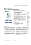
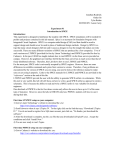
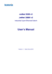
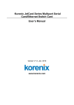
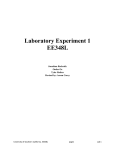
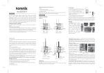
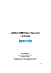
JetNet 6710G-HVDC
Industrial 8-Port PoE plus 2 Gigabit-TX
Managed Ethernet Switch
Quick Installation Guide
V1.6
17-Feb-2014
w w w. ko r e n i x .c o m
1. Overview
The JetNet 6710G-HVDC is Managed Industrial Power over Ethernet
Switches, equipped with eight 10/100 TX ports with 30W/15.4 watts PoE
injector and dual 10/100/1000 TX ports for uplink connection.
By software configuration or by LLDP auto detection, the eight 10/100 TX
PoE injector ports of JetNet 6710G series can deliver 15.4W by IEEE 802.3af
or 30W by the latest High Power PoE IEEE 802.3at standard for supporting
High Power Requiring Devices (PD).
The 2 Gigabit Ethernet ports can provide high speed uplink connectivity to
higher level backbone switches with Korenix MSRTM network redundancy
technology, which can recover any failure in less than 5milliseconds.
To work under vibration and shock environments, the switches are designed
with industrial D-coded M12 connectors or rugged RJ45 connectors to ensure
exceptional solid Ethernet and PoE connections.
1.1. Packing List Checking
Table 1.1-1 Package Content Table
JetNet 6710G-RJ HVDC
JetNet 6710G-HVDC Managed High Power IEEE 802.3at PoE
Switch (M12 / Rugged RJ)
M12-A code 4-Pin Field Site Assembly connector for m12 type
power input
Rugged 4-Pin Field Site Assembly connector for RJ type
power input
M12 to DB9 Shielded Console Cable ( Console Cable)
Rugged M12 D-coded 4-pole Field Assembly Connecter
Rugged M12 A-coded 8-pole Field Assembly Connector
Rugged RJ45 Field Assembly Connecter
2 Wall-Mount kits & 8 Screws
User Manual & QIG in CD-ROM
JetNet 6710G-M12 HVDC
The JetNet 6710G-HVDC series is shipped with the following items. If any of
these items is missing or damaged, please contact your customer service
representative for assistance.
v
v
v
v
8
2
v
v
v
v
10
v
v
1.2. Powering the PoE Switch
The power input rating and wiring specification of JetNet 6710G HVDC series is
listing as below Table 1.2-1.
Input Conductor
Suggest apply Cable
Size
Maximum
Redundant Input
AWG No. / Diameter
Power Input (DC Voltage)
Minimum Recommended
JetNet 6710GM12 HVDC
JetNet 6710G-RJ
HVDC
77
110
137
Yes, V1, V2
AWG 14 / 2.0 mm
77
110
137
Yes, V1, V2
AWG 14 / 2.0mm
Table 1.2-1
Power Input Voltage
The figure 1.2-1 shows the explore diagram of power connector for Rugged RJ45 type 6710G-HVDC Switch.
Figure 1.2-1 Power connector assembly diagram for RJ model
The figure 1.2-2 shows the explore diagram of power connector for m12 type
6710G-HVDC Switch. Notice the rear side polarity for cable conductor
wielding, system won’t active if wrong polarity attached.
Figure 1.2-2 Power connector assembly for M12 type connector
diagram
The figure 1.2-3 shows the power system connection diagram for reference.
Figure 1.2-3 Power System Wiring Diagram
2
2
1.3. RS-232 console and Relay Output Connection
The RS-232 console and the alarm relay are connected via the assembly type
of 5-pole M12 A-coding connector included in the supplied package of JetNet
switch. There are 2 wires nearby the DB-9 connector are relay output wires.
You can connect these 2 wires to trigger alarm system.
Note: these 2 wires will form close circuit when event occurred or system
not ready.
The following diagram shows the pin assignment for console port and alarm
output.
Figure 1.3-1 Console cable pin assignment (cable’s connector pin assignment)
2. Assembly of Ethernet Cables
You can connect terminal devices and other segments via twisted pair cables.
Ports which are not assigned should be closed with the covering caps
contained in the package list of delivery to guarantee the connector is clear
without rust.
Never install or work on/with the equipment or the cabling during the
period of its lightning activity.
2.1 Assembly of M12 Ethernet Connector
For Fast Ethernet M12 D-Code to M12 D-Code connection, you can use either
version below:
1
2
3
4
TX+
RX+
TXRX-
1
2
3
TX+
RX+
TX-
M12-M12 MDI
--------------------------------------------------------------------------------------------------------------------------------------------------------------------------------------------------------------------------------------------------------------------M12-M12 MDI-X
----------------------------------------------------------------------------------------------------------------------------------------------------------------------------------------------------
TX+
RX+
TX RX-
1
2
3
4
RX+
TX+
RX-
2
1
4
4
RX-
------------------------------------------------------------------
TX-
3
Figure 2.1-1 M12-to-M12 Ethernet Cable Wiring
For Fast Ethernet M12 D-Code to RJ45 connection, the pin assignment of the
patch cable is shown below:
1
2
3
4
TX+
RX+
TX RX-
1
2
3
4
TX+
RX+
TX RX-
M12-RJ45 MDI
--------------------------------------------------------------------------------------------------------------------------------------------------------------------------------------------------------------------------------------------------------------------M12-RJ45 MDI-X
---------------------------------------------------------------------------------------------------------------------------------------------------------------------------------------------------------------------------------------------------------------------
RX+
TX+
RXTX -
3
1
6
2
RX+
TX+
RXTX -
1
3
2
6
Figure 2.1-2 M12-to-RJ45 Ethernet Cable Wiring
For Gigabit Ethernet M12 A-Code to RJ45 connection, the pin assignment of
the patch cable is shown below,
Figure 2.1-3 Gigabit M12-to-RJ45 Ethernet Cable Wiring
For Gigabit Ethernet M12 A-Code to M12 A-code connection, the pin
assignment of the patch cable is shown below:
2.2. Assembly of Rugged RJ45 Connector
The RJ version provides robust connection by the field assembly capable
rugged RJ45 connector. Each component of the connector is shown below:
Figure 2.2-1 Rugged RJ45 Connecter Components
Follow the steps to assemble the rugged RJ45 connector:
Figure 2.2-2 Rugged RJ45 Cable Connection diagram
Following Figure 2.2-3 shows the color code of Cat.-5E UTP/STP cable based
on the two standards released by TIA/EIA – 568A and 568B. The 568B wiring
is by far, the most common wiring method. You can choose the method that
suits your application; but ensure that both ends of the cable use the same
standard.
Figure 2.2-3 RJ45 Cable color code
3. Device Management
JetNet 6710G or 6810G series switches provide both in-band and out-band
configuration methods. You can configure the switch via the RS232 console with
the attached console cable, or you can remotely manage the switch via network
using Telnet/SSH, Web/HTTPS management.
3.1 Preparation for console management
Attach the RS-232 DB9 connector to your PC’s COM port. Connect the M12 Acode 5-pin connector to the console port of the JetNet 6710G or 6810G.
3.1.1 Go to Start -> Program -> Accessories -> Communication -> Hyper
Terminal
3.1.2 Give a name to the new console connection to create a new serial
communication session.
3.1.3 Choose the COM name, and select the correct serial settings. The serial
settings of JetNet 6710G or 6810G are as below:
Baud Rate: 9600 / Parity check: None / Data Bit: 8 / Stop Bit: 1
3.1.4 After connected, you can see Switch login request. Type-in the username
and password to login. The default username is “admin”, password is “admin”
for console interface.
3.1.5 Follow the manual to configure the device features.
3.2 Preparation for Web management
Before you attempt to use the embedded web interface to manage switch
operation, verify that your JetNet switch is properly installed on your network and
that every PC on this network can access the switch via the web browser.
3.2.1 Launch the web browser (Internet Explorer or Mozilla Firefox) on the PC.
3.2.2 Type http:// 6710G_IP_Address or 6810G_IP_Address (The default IP
address is 192.168.10.1.), then press Enter.
3.2.3 The login screen will appear next. Type-in the user name and the
password. The default user name and password is admin/admin.
3.2.4 Click OK, and then the welcome page of the web-based management
interface will appear.
At the left column of the Web management interface are listed the available
software features; by pressing the ring column you can also view the detailed
configuration interface.
For more detailed management features please refer to the software’s
users’ manual. The software user manual can be downloaded from
Korenix Website as below:
http://www.korenix.com/downloads.htm
Korenix Technologies Co., Ltd.
Business service: [email protected]
Customer service: [email protected]