1
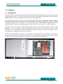
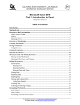
BP51800 Blade Profiler User Manual Rev 1.08 51800MN000-A00 Blade Profiler Blade Profiler User Manual © Copyright by Degree Controls, Inc. All Rights Reserved. This publication may be reproduced for use of registered users of Degree Controls, Inc. products. For all other purposes reproduction, storage or transmission in any form or by any means, electronic, mechanical, photocopying, recording or otherwise, requires prior permission of Degree Controls, Inc. Printed in U.S.A. Part No.: 51800MN000-A00 This publication may include words that are or are asserted to be proprietary names. The presence or absence of such assertions should not be regarded as affecting the legal status of any proprietary name or trademark. Customer Service : Mailing address: Degree Controls, Inc. 18 Meadowbrook Drive Milford, NH 03055 USA Telephone: 603-672-8900 or 1-877-DEGREEC Fax: 603-672-9565 Website www.DegreeC.com Sales, Support, Service: Customer.service @degreec. com www.degreeC.com 2 51800MN000-A00 Blade Profiler Customer Service Information This section provides information about Degree Controls, Inc.’s Customer Service policy, installation policy, and warranty. Degree Controls, Inc.’s policies on warranty returns and consumable parts are also explained. To determine which policies apply to your system, consult Degree Controls, Inc. Customer Service Policy Degree Controls, Inc. has established a Customer Service department to meet the service needs of its customers. A Customer Service Representative is available from 9:00 a.m. to 5:00 p.m. (EST). Technical Support For technical assistance, contact [email protected], Inc. or call 1-877-degreec. Warranty Information Degree Controls, Inc. products purchased in the USA or Canada are warranted to be free from defects in materials or workmanship for a period of 1 Year from the date of their original purchase. If a sensor or instrument fails to perform to this warranty, we will, at our own option and at no cost to the customer, replace or repair it within a reasonable timeframe. This warranty does not cover defects, malfunction, or failures resulting from shipping or transit accidents, misuse, operation contrary to furnished instructions, modification, tampering, or normal wear and tear. Returns Within the above period, any part of the goods that prove to be defective in material or workmanship may be repaired or replaced on an exchange basis with a new or equivalent part free of charge. After such warranty period, any labor, travel time, transportation and travel & living expense shall be borne by the Buyer. If preferred, Buyer may return goods to Degree Controls, Inc.’s manufacturing plant with shipment both ways at Buyer’s expense for repair work. Parts returned damaged due to poor or insufficient packaging by the Buyer will not be accepted for service unless otherwise agreed. Parts returned with no manufacturing defects found, will incur a service/handling charge. In no event shall Degree Controls, Inc. be liable for incidental or consequential damages, including, but not limited to, costs, or removal and reinstallation or such goods, good will, overhead expenses, loss of profit, and loss of use. The remedies are available only to the original Buyer. Buyer agrees to accept billing for service expense for service call resulting from other than a Degree Controls, Inc. goods failure or other Degree Controls, Inc. fault. www.degreeC.com 3 51800MN000-A00 Blade Profiler About this Manual This User Manual provides the information necessary to setup and use the Accusense Blade Profiler Instrument. All operating instructions, functional descriptions, illustrations, and other relevant information are contained in this manual. Descriptions of the system hardware and software are included. Systematic instructions guide you through all installation procedures and describe all operating software. Starting Out If you are placing your Blade Profiler in service for the first time, Degree Controls, Inc. recommends working through this Manual following the step-by-step instructions provided. If you need additional help as you move through these procedures, contact your regional Degree Controls, Inc. representative or Degree Controls, Inc.’s Technical Support for assistance. Design Change Notice Due to design changes and product improvements, information in this manual is subject to change without notice. Degree Controls, Inc. reserves the right to change hardware and/or software design at any time, which can affect the contents of this manual. Degree Controls, Inc. assumes no responsibility for errors of omission or content in this manual. We will make every reasonable effort to ensure that this user manual is up to date and corresponds with your shipped instrument. Types of Messages The following describes the types dangers, cautions, warnings that are used in this manual. DANGERS, NOTES, WARNINGS and CAUTIONS: Below are important notices and safety instructions. Please read carefully, and follow all warnings and instructions marked on the sensor and in this manual. DANGER: Indicates situations that could result in the injury or death of a human operator or bystander. Warnings are printed in all upper case characters in boldface type, between two heavy horizontal rules, as in the following example: DANGER: FAILURE TO PROPERLY GROUND THE INSTRUMENT MAY RESULT IN ELECTROCUTION OR SEVERE INJURY TO THE OPERATOR. www.degreeC.com 4 51800MN000-A00 Blade Profiler CAUTION: Indicates situations that could damage the Instrument and/or Sensors, or cause injury to an operator. Cautions are printed in mixed upper- and lower-case characters in boldface type, between two heavy horizontal rules, as in this example: CAUTION: Failure to connect the instrument to the proper electrical voltage as specified herein could result in damage to the power supply and instrument. NOTES: indicate miscellaneous information. Notes are printed in mixed case characters, in normal type, between two heavy horizontal rules, as in this example: NOTE: For details on Degree Controls, Inc. customer service policies, refer to Preface A. www.degreeC.com 5 51800MN000-A00 Blade Profiler Dangers, Cautions, and Notes for the Blade Profiler Below are important safety instructions for the Blade Profiler. Please read carefully, and follow all warnings and instructions. DANGER: NEVER INSTALL OR OPERATE THE DEGREE CONTROLS, INC. BLADE PROFILER WHILE IN CONTACT WITH WATER. YOU MAY BE ELECTROCUTED! DANGER: DO NOT TRY TO REPAIR AN INSTRUMENT OR SENSOR YOURSELF. THERE ARE NO CUSTOMER-SERVICEABLE PARTS INSIDE. OPENING THE CASE PRESENTS A DANGER OF ELECTRIC SHOCK, AND VOIDS THE DEGREE CONTROLS, INC. WARRANTY. DANGER: IF ANY OF THE FOLLOWING CONDITIONS OCCURS, TURN OFF THE INSTRUMENT IMMEDIATELY, UNPLUG THE POWER CORD FROM THE ELECTRICAL OUTLET, AND CONTACT DEGREE CONTROLS, INC.: If smoke, abnormal noise, or any strange odor is present. If liquid has been spilled over or into the instrument. If the instrument has been dropped or damage is visible. CONTINUING TO USE THE BLADE PROFILER INSTRUMENT IN THE EVENT OF ANY OF THE ABOVE CONDITIONS CAN RESULT IN DAMAGE TO THE EQUIPMENT AND INJURY TO THE OPERATOR! CAUTION: Avoid exposing the Instrument to dust, rain, and (condensing) water. Water can cause shorts, corrosion, and, at a minimum, inaccurate readings. CAUTION: Use a power cable that is properly grounded. Always use the power cord that is provided with the Blade Profiler. CAUTION: The Blade Profiler is an ESD sensitive device. The Blade Profiler has a connector that allows you to connect to an ESD wrist strap. Be sure to place the Blade Profiler on an ESD mat and attach the wrist strap appropriately. CAUTION: The Blade Profiler is designed for use in a lab environment measurement. Air containing chemicals (for example, hazardous gases) may damage the internal sensor heads. Note: Chemicals may change the heat capacity of the air so that the calibration of the device is no longer accurate. www.degreeC.com 6 51800MN000-A00 Blade Profiler CAUTION: Properly ground the Blade Profiler to a known earth ground NOTE: Avoid exposing the Instrument to direct sunlight or other heat sources. Do not store the equipment in an extreme hot or cold environment. NOTE: Keep the Instrument away from magnets, motors, transformers, speakers, and televisions. www.degreeC.com 7 51800MN000-A00 Blade Profiler 1. INSTALLATION ................................................................................................................11 1.1 Introduction...................................................................................................................................11 1.2 SYSTEM BLOCK DIAGRAM ...................................................................................................12 1.3 SYSTEM CONTENTS .................................................................................................................13 1.4 SYSTEM REQUIREMENTS ......................................................................................................13 1.4.1 Hardware Requirements...........................................................................................................13 1.4.2 Software Requirements ............................................................................................................13 1.5 Hardware Installation and Setup ................................................................................................13 1.6 Software Installation.....................................................................................................................14 1.7 Blade Profiler Software Overview...............................................................................................14 1.7.1 Blade Profiler Configuration Tab.............................................................................................14 1.7.2 Result Tab ................................................................................................................................16 1.7.3 About Tab ................................................................................................................................17 1.8 Blade Profiler - Automatic Testing .............................................................................................18 1.8.1 Starting the Blade Profiler........................................................................................................18 1.8.2 Configuring the COM Port setting ...........................................................................................18 1.8.3 Selecting Test Type..................................................................................................................19 1.8.4 Loading the LookUp Table ......................................................................................................20 1.8.5 Loading the Board Under Test .................................................................................................20 1.8.6 Starting the test cycle ...............................................................................................................21 1.8.7 Generating the Blade Profile Report ........................................................................................21 1.9 Blade Profiler - Manual Testing ..................................................................................................23 1.9.1 Starting the Blade Profiler........................................................................................................23 1.9.2 Configuring the COM Port setting ...........................................................................................24 1.9.3 Selecting Manual Test Type.....................................................................................................24 1.9.4 Selecting the Load Lookup Table ............................................................................................25 1.9.5 Loading the Board Under Test .................................................................................................26 1.9.6 Starting the test cycle ...............................................................................................................26 1.9.7 Generating the Profile Report ..................................................................................................26 2. ADAPTER AND TEST BOARD SETUP ...........................................................................28 3. INTERPRETING THE RESULTS ......................................................................................29 3.1 Front Board ...................................................................................................................................29 www.degreeC.com 8 51800MN000-A00 Blade Profiler 3.2 RTM ...............................................................................................................................................30 3.3 AMC/PCI/VME ............................................................................................................................32 4. TROUBLE SHOOTING .....................................................................................................33 5. TECHNICAL SUPPORT....................................................................................................37 6. MAINTENANCE PROCEDURE ........................................................................................37 6.1 Recalibration .................................................................................................................................37 6.2 Cleaning .........................................................................................................................................38 www.degreeC.com 9 51800MN000-A00 Blade Profiler www.degreeC.com 10 51800MN000-A00 Blade Profiler 1. Installation 1.1 Introduction The Blade Profiler is designed to profile the flow impedance of a board by measuring velocity versus pressure drop and plotting the Q-P curve. The system can profile front ATCA boards and RTM boards when used with the RTM Adapter Module. With special adapters it can also profile VME and PCI cards. In an open platform, such as ATCA, where the shelf and blades may be supplied by different vendors, interoperability is assured by strict adherence to design standards. The shelf is designed to provide specific airflow and pressure characteristics on each blade slot. It is the responsibility of the blade designer to adequately utilize the available airflow. The prime factor that determines the amount of airflow over a blade is its airflow impedance. The Blade Profiler is an automated wind tunnel from DegreeC that is used as a testing instrument to measure blade impedance. It was developed for airflow impedance measurement of an ATCA Front board. With it a flow impedance scan of an individual board can be determined in a matter of minutes. This assures compliance with the flow impedance requirement specified in the CP-TA ICD. The Blade Profiler Software turns your PC into a powerful test and analysis center. It performs a sweep of the air velocity and collects airflow, and pressure drop data. The report generated contains impedance curve and flow distribution. You can print the summary test report or save it and email it to its destination. Figure 1 www.degreeC.com 11 51800MN000-A00 Blade Profiler 1.2 SYSTEM BLOCK DIAGRAM Figure 2 www.degreeC.com 12 51800MN000-A00 Blade Profiler 1.3 SYSTEM CONTENTS The Blade Profiler ships in a case with the following items: The Blade Profiler instrument Power Supply – 24Vdc, 2.5A USB cable CD-ROM with Software, drivers, user manual, and instrument calibration file RTM Adapter to test RTM boards Blade Profiler shipping / carrying case Ground Wire 1.4 SYSTEM REQUIREMENTS The computer that is used with the Blade Profiler must meet the following requirements: 1.4.1 1.4.2 Hardware Requirements Processor: AMD 3000 Class or Pentium 4 Ram 512mb Minimum Hard Drive: 40 Gig Minimum Microsoft “XP” Professional with SP2 CD-ROM Drive One available USB 1.1 or 2.0 USB Port Software Requirements .NET framework - During the installation process you have the option of installing this if it is not already present on the system. Microsoft Excel – version 2002 or higher 1.5 Hardware Installation and Setup Always use an ESD wrist strap and Earth Ground strap when using the Blade Profiler. The Blade Profiler should be placed upon an ESD mat and attached to ground using the GND connector on the side of the instrument. There are two connectors for ESD protection, one for the ESD mat and the second for an ESD wrist strap. 1.5.1 Plug the USB cable into the PC or laptop 1.5.2 Plug the other end of the USB cable into the Blade Profiler’s USB port 1.5.3 Plug the power supply into the AC outlet, and the DC jack into the Blade Profiler www.degreeC.com 13 51800MN000-A00 Blade Profiler 1.6 Software Installation 1.6.1 Place the CD-ROM supplied with the Blade Profiler into your computer’s CD drive. Navigate to the Dot Net 2.0 Setup folder and run DOTNETFX. This will install .NET from the CD-ROM. 1.6.2 Navigate to the Blade Profiler Setup folder. Double click on setup to install the blade profiler software. 1.6.3 Navigate to the CDM Driver Setup folder and double click on the CDM Setup to install the CDM drivers. 1.6.4 Navigate to the Templates folder on the CD. Copy all files from the templates folder to your \degreec\bladeprofiler subdirectory. 1.7 Blade Profiler Software Overview The Blade Profiler software communicates with the instrument and takes the pressure and airflow readings across the test board at different fan speeds and then plots the P-Q curve. The software provides two different modes of operation - Automatic Mode and Manual Mode. In automatic mode the fan speed changes automatically based on a fan speed file. In manual mode, the user specifies the speed and runs the system manually. The Blade Profiler software has 3 display tabs: 1.7.1 Blade Profiler Configuration Tab The configuration tab allows the user to set specific parameters for instrument use such as automatic versus manual test types, fan speed, and English versus metric units. Please refer to Figure 3. Figure 3 www.degreeC.com 14 51800MN000-A00 Blade Profiler Refresh Com Ports – The Refresh Com Ports button is used to identify which com port the Blade Profiler is connected to on your computer. The com port selections are identified in the drop down box next to the Refresh Com Ports button. Typically the correct number is the highest number. It will not be 1 or 2. If there are no higher numbered ports shown please refer to the troubleshooting section. Run - The Run button is used to start the Blade Profiler. Prior to starting the collection of data by using the Run button, use the Test Type and Units drop down boxes to refine the mode of your data collection. Load Lookup Table – This drop down is used to select the proper lookup table file for the test. Make Blade Profile Report – When the test process is completed this button is used to create the analysis report. Test Type - Test type selections are either Automatic Testing or Manual Testing. The Automatic mode uses a predetermined set of fan speeds for the data collection. Manual mode allows you to enter fan speeds manually for data collection. Units – Identifies the test unit for the results. Units are either English or Metric. % Fan Speeds – The fan speeds to run the test are shown in the box labeled % Fan Speeds. You may add to or subtract from this list or create a list of your own. Adapter – When using the Blade Profiler you must identify which adapter is installed in the system. Use the drop down box to identify the loaded adapter. Airflow sensors inside the instrument that are not used will be ignored during data collection. Status – The Blade Profiler Status field shows the current status of the instrument. The settings are: Idle Mode: The Blade Profiler is not running. Loading Excel Pages: This status is seen when the system is loading the Excel templates during setup. Speed – The input field labeled Speed is used to enter new fan speeds into the % Fan Speed box. Add – Used to add a fan speed into the fan speed setting. Enter the new % of fan speed into the blank box and click the Add button. Remove – Used to remove fan speeds from the fan speed settings. Highlight the fan speed to be deleted and click the Remove button. Default – Reloads the default fan speed settings. Save Fan Speed – Saves the fan speed settings. www.degreeC.com 15 51800MN000-A00 Blade Profiler 1.7.2 Result Tab The Blade Profiler software allows the user to review data collected in the Result tab of the application. The results are populated and saved into an Excel spreadsheet showing tab ular and graphical display of airflow and pressure sensor readings. The Excel spreadsheet is provided as a predefined template when the software is installed. The software performs a conversion of LFM values to CFM values on the basis of a predefined LookUp table. The LookUp table is installed during the Blade Profiler software installation process. Both the Excel templates and LookUp table must be properly selected or the software will not work appropriately. Selecting the Result Tab allows you to review the data collected from the test. It can be selected and reviewed while the instrument is actively collecting data. Refer to Figure 4. Figure 4 Result Columns: S.I – Index of the data collection point. Speed % - The fan speed for the data points in the row. Pressure WC – Air pressure inside the unit during the data collection shown in column of water. Total CFM – Total Air flow shown in cubic feet per minute when English units are selected. It is shown as CMS (cubic meters per second) when Metric units are selected. Sensor 1 (LFM) – Sensor 8 (LFM) - The recorded air flow for each of the sensors. This is shown in linear feet per minute or meters per second depending on the selection of English or Metric units on the configuration tab. The location of the air flow sensors is indicated on the outside of the Blade Profiler. www.degreeC.com 16 51800MN000-A00 Blade Profiler 1.7.3 About Tab The About Tab shows the Software Revision and firmware revision of the Blade Profiler instrument as shown in Figure 5 below. Figure 5 www.degreeC.com 17 51800MN000-A00 Blade Profiler 1.8 Blade Profiler - Automatic Testing 1.8.1 Starting the Blade Profiler Start the Blade Profile software from the start up menu as shown in Figure 6. Figure 6 1.8.2 Configuring the COM Port setting To select the COM port that the Blade Profiler is connected to on your computer, click on the arrow next to the Drop down list as shown in Figure 7. This will show all of the COM channels on your computer. Click on the REFRESH COM PORTS button to scan for the latest updated USB connection. This should be the correct COM port#. (It will not be 1 or 2.) Refer to the Troubleshooting section for more help. www.degreeC.com 18 51800MN000-A00 Blade Profiler Figure 7 1.8.3 Selecting Test Type In the drop down box labeled Test Type select Automatic Testing as shown in Figure 8. Figure 8 During Automatic Testing the fan speeds will be taken from the configuration file that is loaded on the system. The speeds are shown in the box labeled % Fan Speeds. www.degreeC.com 19 51800MN000-A00 Blade Profiler You may create your own set of fan speeds. To remove a specific fan speed, highlight the fan speed using your mouse and click on the remove button. To add a new fan speed type the fan speed into the box labeled Speed and click on the Add button. The new fan speed will be added to the display of Fan Speeds. Note that the new template will not be saved until you click on the Save Fan Speed button. You may use this new fan speed (or set of fan speeds) during the current session but they will not be saved and available for the next session unless the Save Fan Speed button is clicked. To revert back to the saved fan speeds click on the Default button. Once you have saved the new fan speeds it will become the default. 1.8.4 Loading the LookUp Table Select the LOAD LOOKUP TABLE button to open a browse window. Use this to navigate to, select, and open the “Look-Up Table.xls” file. The serial number on the look-up table must match the serial number of the Blade Profiler. Also, make sure that you select the proper look-up table for the adapter you are using. The Look-Up Table contains the the calibration file for the system and must not be changed in any manner. Do not edit this file. Refer to Figure 9. Figure 9 1.8.5 Loading the Board Under Test Once the software is fully configured the adpater and board to be tested must be loaded into the test section. This is done by sliding the board into the test section and using the board’s upper and lower latching mechanisms to ensure proper fit. Refer to section 2 for setup of the adpaters and test boards. Note: Verify that the EMI gasket is in place on the faceplate edge to prevent air leakage. www.degreeC.com 20 51800MN000-A00 Blade Profiler 1.8.6 Starting the test cycle Note: Please allow a minimum of 30 minutes of warmup prior to taking measurements with the Blade Profiler. To warm up the Blade Profiler, power it on, and run it in manual mode at 100% fan speed for appoximately 30 minutes. The goal is to run the actual test right after the warm up period ends....without letting it cool down Click the RUN button to start the test. While running, the STOP button will appear instead of the RUN button. Notice that the status area now indicates the system is running. The unit will automatically step through and collect data at each of the programmed fan speeds unless the user presses the STOP button. When the automatic test sweep is completed, the software will prompt you with the message shown below: Figure 10 1.8.7 Generating the Blade Profile Report Make sure excel is not already open. Click the Make Blade Profile report button and select the corresponding report template file in the DegreeC folder on the PC. This template will be an excel file that came on the installation disk with the lookup table. After you click the buton the system will open the file and fill in the collected data. To save the report, use the Save As function in excel. Your report will look similar to the report in Figure 11. www.degreeC.com 21 51800MN000-A00 Blade Profiler Figure 11 If you click on the data tab at the bottom of the report it will open the excel file of collected data as shown in Figure 12. www.degreeC.com 22 51800MN000-A00 Blade Profiler Figure 12 1.9 Blade Profiler - Manual Testing 1.9.1 Starting the Blade Profiler Start the Blade Profile software from the start up menu as shown in Figure 13. Figure 13 www.degreeC.com 23 51800MN000-A00 Blade Profiler 1.9.2 Configuring the COM Port setting To select the COM port that the Blade Profiler is connected to on your computer, click on the arrow next to the Drop down list as shown in Figure 14. This will show all of the COM channels on your computer. Click on the REFRESH COM PORTS button to scan for the latest updated USB connection. This should be the correct COM port#. (It will not be 1 or 2.) Figure 14 1.9.3 Selecting Manual Test Type Select Manual Test from the Test Type drop down menu as shown in Figure 15. In Manual testing you must specify the fan speed. Type the fan speed in the SPEED box, and click the ADD button. Specify the number of times to run the manual test by selecting the drop down next to the SAMPLES box. Use the up or down arrow to increase the number of samples run. You may also type in the number of samples you wish to record. If you set SAMPLES = 0, the Blade Profiler will run continuously. If the SAMPLES = 1, the system will run once and display the data. Once the samples have been recorded you can change the speed and press RUN to collect the next set of data. www.degreeC.com 24 51800MN000-A00 Blade Profiler Figure 15 Figure 16 1.9.4 Selecting the Load Lookup Table Select the LOAD LOOKUP TABLE button to open a browse window. Use this to navigate to, select, and open the “Look-Up Table.xls” file. The serial number on the look-up table must match the serial number of the Blade Profiler. Also, make sure that you select the proper look-up table for the adapter you are using. The Look-Up Table contains the the calibration file for the system and must not be changed in any manner. Do not edit this file. Refer to Figure 17. www.degreeC.com 25 51800MN000-A00 Blade Profiler Figure 17 1.9.5 Loading the Board Under Test Once the software is fully configured the adpater and board to be tested must be loaded into the test section. This is done by sliding the board into the test section and using the board’s upper and lower latching mechanisms to ensure proper fit. Refer to section 2 for setup of the adpaters and test boards. Note: Verify that the EMI gasket is in place on the faceplate edge to prevent air leakage. 1.9.6 Starting the test cycle Click the RUN button to start the test. The system will execute for the specified number of runs and then stop. If you need to stop in the middle of the test, click the STOP TEST button. 1.9.7 Generating the Profile Report The Make Profile Report button will generate a Test report of the acquired data. When you click on the button another window will open as shown in Figure 19. Use your mouse to highlight the “BP Sample Template.xls” file. You will need to choose the proper template either the BP FB template, the BP RTM template or the BP AMC/PCI template depending upon which adapter you are using. Then press the Open button. The file will open and the acquired data will be placed into the Excel spreadsheet as shown in Figure 18. www.degreeC.com 26 51800MN000-A00 Blade Profiler Figure 18 Figure 19 Clicking on Sheet1 will show you the Test report with the charts. Sheet2 shows the raw data in English units, and Sheet3 shows the raw data in Metrics units. www.degreeC.com 27 51800MN000-A00 Blade Profiler 2. Adapter and Test Board Setup When testing your board you must select the proper adapter and lookup table. In addition, it is important to pinch the pressure ports closed if required. Use the table below (Figure 21) to determine your test setup. The port reference is 1-4 with #1 being on the side where the USB cable is plugged into the unit and #4 the furthest from the power cable plug. The pressure ports are pinched shut by using the clip that can be found on each of the four clear tubes on the top of the instrument. Board Under Test Adapter Front Board RTM AMC - Full Height Single Wide AMC - Half Height Single Wide AMC - Full Height Double Wide AMC - Half Height Double Wide VME PCI *The proper blockages will need to be Pinched Pressure Ports Look Up Table Extension Template None None ...FB Look up table RTM 1,2,3 ...RTM look up table AMC* 4 ...AMC .33 inch Height Look up table AMC* 4 ... AMC .5 inch Height Look up table AMC* 4 ...AMC double .33 inch Height Look up table AMC* 4 ...AMC double .5 inch Height Look up table AMC* 4 ...VME and PCI Look up table AMC* 4 ...VME and PCI Look up table afixed to the AMC adapter depending on the type of card under test Figure 21 www.degreeC.com 28 51800MN000-A00 FB RTM AMC AMC AMC AMC AMC AMC Blade Profiler 3. Interpreting the Results 3.1 Front Board The goal in interpreting the Blade Profiler results is to determine whether or not the board under test (BUT) is in alignment with the CP-TA Front Board Reference Curve (FBRC). Since the Blade Profiler software automatically displays the curve of the BUT in comparison with the FBRC all that is needed is a simple visual examination. To do this, open the report of the BUT. The redline displayed on the graph represents the CP-TA FBRC curve while the blue line is composed of the test data for the BUT. If the BUT curve is above the CP-TA FBRC (see figure 22 below) then the BUT is of HIGHER impedance than the CP-TA FBRC. 0.45 Pressure (Inch H2O) 0.4 0.35 0.3 0.25 0.2 Front Board Reference 0.15 0.1 0.05 0 0 10 20 30 40 50 Airflow (CFM) Figure 22 Pressur e (Inch H2O ) If the BUT curve is below the CP-TA FBRC (see figure 23) then the BUT is of LESSER impedance than the CP-TA 0.4 FBRC. Front Board Reference 0.35 0.3 0.25 0.2 0.15 0.1 0.05 0 0 10 20 30 40 50 60 Airflow (CFM) Figure 23 www.degreeC.com 29 51800MN000-A00 Blade Profiler If the BUT curve coincides to the CP-TA FBRC as in figure 24 then the BUT is of EQUAL impedance than the CPTA FBRC. 0.4 Front Board Reference Pressure (Inch H2O) 0.35 0.3 0.25 0.2 0.15 0.1 0.05 0 0 10 20 30 40 50 Airflow (CFM) Figure 24 The goal is to have the BUT curve align with the CP-TA FBRC as closely as possible. When the two resistances are equal a chassis will be able to offer uniform airflow to all slots when it is populated with CP-TA qualified boards. If the BUT offers less impedance than the CP-TA FBRC when placed in the chassis the board will draw more air from the chassis airflow system than was intended. A possible side effect of this additional airflow is the starving of other slots in the chassis that are of higher impedance. The opposite effect of this occurs when the BUT provides higher impedance than the CP-TA FBRC. When placed into the chassis the board will force air into the other chassis slots and starve itself because it offers too much resistance to the chassis airflow system. 3.2 RTM Interpreting the Blade Profiler results for an RTM test is very much the same as interpreting the FB results. Again it should be visually determined whether the BUT is above or below the CP-TA RTM Reference Curve (CP-TA RTMRC). Whether the BUT is above, below, or equal to the CP-TARTMRC determines whether the BUT is of higher, lower, or of similar impedance to the CP-TA recommended impedance. See the following graphs for examples of each case. If the BUT curve is above the CP-TA RTMRC (see figure 24) then the BUT is of HIGHER impedance than the CPTA RTMRC. www.degreeC.com 30 51800MN000-A00 Blade Profiler 0.45 RTM Reference Pressur e (Inch H2O ) 0.4 0.35 0.3 0.25 0.2 0.15 0.1 0.05 0 0 2 4 6 8 10 12 Airflow (CFM) Figure 24 If the BUT curve is below the CP-TA RTMRC as in figure 25 then the BUT is of LESSER impedance than the CPTA RTMRC. 0.45 RTM Reference Pressur e (Inch H2O ) 0.4 0.35 0.3 0.25 0.2 0.15 0.1 0.05 0 0 2 4 6 8 10 12 Airflow (CFM) Figure 25 If the BUT curve coincides to the CP-TA RTMRC (refer to figure 26) then the BUT is of EQUAL impedance than the CP-TA FBRC. www.degreeC.com 31 51800MN000-A00 Blade Profiler 0.45 RTM Reference Pressur e (Inch H2O ) 0.4 0.35 0.3 0.25 0.2 0.15 0.1 0.05 0 0 2 4 6 8 10 12 Airflow (CFM) Figure 26 If the BUT curve is below the CP-TA FBRC (figure 27) then the BUT is of LESSER impedance than the CP-TA FBRC. Pressur e (Inch H2O ) 0.4 Front Board Reference 0.35 0.3 0.25 0.2 0.15 0.1 0.05 0 0 10 20 30 40 50 60 Airflow (CFM) Figure 27 The goal again is to have the impedance of BUT match the CP-TA RTMRC as closely as possible. A BUT impedance that is higher or lower than the CP-TA RTMRC can lead to the effects previously described for the FB once placed in the chassis. 3.3 AMC/PCI/VME Currently there is not a reference curve available from the CP-TA Thermal Task Force for AMC, PCI, or VME cards. However the information provided by the Blade Profiler can still be useful in determining the amount of airflow a board will receive inside a chassis as well as what type of resistance a board will pose. www.degreeC.com 32 51800MN000-A00 Blade Profiler 4. Trouble Shooting At the time of installation, you may face some obstacles if the minimum system requirements are not met. Some of these issues are mentioned in this section, along with suggested solutions to overcome this issue. Missing .Net 2.0 Framework. While installing the Blade Profiler Software, if .NET 2.0 frame work is not in installed on the system the installer will automatically prompt for the installation of .net framework from internet as shown in Fig 20. The software may also be downloaded from Microsoft’s website. Figure 28 Step1: Accept the agreement to install .net 2.0 framework. Step 2: The installation will proceed as shown in Figure 29 Figure 29 www.degreeC.com 33 51800MN000-A00 Blade Profiler Com Port Number is Not correct While using the software for testing, if an error occurs which indicates a problem in communication or access to the com port, click on the REFRESH COM PORT button to select the correct com port that is assigned to the Blade Profiler. Steps to check the Com Port Number: Step 1: Right click on My Computer -> Properties. A window shown in Figure 30 will be displayed. Figure 30 Step 2: Select the Hardware tab and click the Device manager button as shown in Figure 31. www.degreeC.com 34 51800MN000-A00 Blade Profiler Figure 31 Step 3:The Device Manager page will be displayed as in Figure 32. Figure 32 Step 4: Select Ports(COM & LPT) from the list displayed in device manager as shown in Figure 33 and note the com port for the Blade Profiler. Note: You may need to unplug the Blade Profiler from your PC, wait a few seconds and then reconnect the Blade Profiler to reestablish communications. www.degreeC.com 35 51800MN000-A00 Blade Profiler Figure 33 Some of the sensors are only showing 0’s On the configuration tab, check to make sure you have selected the proper adapter. I Changed Adapters but the results are still off Check to make sure the that only the pressure tubes that are in the airflow path are open and all of the tubes not in the airflow path are closed. I click on start test and the software indicates the test is running but the Blade Profiler is not running Make sure that the USB cable is connected. Verify that the 24V 2.5A power cable is connected. Following 2.2 above make sure that the COM port is correct. Restart the Blade Profiler and the sofware Verify that the drivers are installed and that the Load VCP setting is on. Do this by navigating into the Windows device manager and check to make sure there is a Serial Convert A and B under USB devices. Right click on Serial Converter B and make sure Load VCP is checked. If you change any settings you will need to restart your computer and the Blade Profiler. How do I determine the Serial Number of my Blade Profiler? The serial number is located on the white sticker on the side or bottom of the Blade Profiler. www.degreeC.com 36 51800MN000-A00 Blade Profiler I left the Blade Profiler running and when I came back it wasn’t communicating If the computer goes into standby mode this may happen. Restart the Blade Profiler and software. I receive an error message from the Blade Profiler software that says “unable to write to excel” Close all open excel windows and try again. When I click Make Blade Profile Report and I type in what I want the report to be named I receive an error message. You cannot type in the name of the report at this point. You may only select the template. Find the correct template that came with the Blade Profiler. When the report opens in exceI go to file, save as and name your report. I can’t save my report – I get an error message “BP Template FB.xls is a read only file” Use the save as function to save a copy with a new name. Do not save over the template. 5. TECHNICAL SUPPORT If you experience difficulty running your Blade Profiler System, please contact your Degree Controls, Inc. Representative or Degree Controls, Inc. Tech Support. Customer Service is available weekdays from 9:00 AM to 5:00 PM Eastern Time. You may reach them at 1-877-DEGREEC or at [email protected] . Visit our website www.degreec.com for additional information. 6. MAINTENANCE PROCEDURE Degree Controls, Inc. guarantees the calibration of the Blade Profiler Series instruments and the sensors for one (1) year starting the day of delivery. 6.1 Recalibration To ensure that your Blade Profiler always gives the most accurate readings, Degree Controls, Inc. recommends that the system be recalibrated once every year. To recalibrate, contact Degree Controls, Inc. for an RMA-number and shipping instructions before returning the unit. To check if the Blade Profiler’s airflow sensors are still accurate, compare the readings to a sensor of the same type and location/flow. Ensure that the air velocity matches the sensor ’s calibration range. WARNING: THERE ARE NO CUSTOMER SERVICEABLE PARTS INSIDE THE BLADE PROFILER. OPENING THE CASE AFFECTS THE DEGREE CONTROLS, INC. WARRANTY AND RISKS ELECTRIC SHOCK! www.degreeC.com 37 51800MN000-A00 Blade Profiler 6.2 Cleaning BEFORE CLEANING – power off the instrument, unplug all power and USB cable To clean the instrument, use a moist cloth and wipe it down dry. Do not use alcohol or ammonia based solutions. www.degreeC.com 38 51800MN000-A00 Blade Profiler www.degreeC.com 39 51800MN000-A00