1
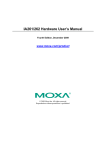
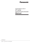
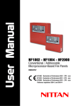
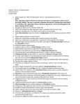
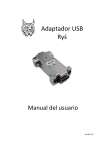
2 Zones
Master & Slave
Fire Alarm Control Panel
User & Installation Manual
ZONE1
ZONE2
SOUND
ZONE1
ZONE2
SOUND
A
A
A
A
A
A
F
F
F
F
F
F
EVACUATE
SILENCE
TEST/RESET
EVACUATE
SILENCE
TEST/RESET
Master Panel
Slave Panel
IMPORTANT
This manual should be left with the panel after installation.
We reserve the right to change product specifications without
prior notice.
Notes
INSTRUCTION MANUAL
3
Introduction
The information provided in this manual covers the
Master and Slave fire alarm control panel. The panel
range is designed to meet the requirements of EN54
Parts 2 & 4.
This product should be installed, commissioned and
maintained by suitably qualified service personnel
with reference to IEE regulations and any statutory
requirements.
4
FIRE ALARM PANEL
Using the metal box as a template, mark the position
of the fixing holes on the wall. Drill and plug the wall,
then screw the panel to the wall. Ensure the panel
is free from knockout discs, swarf and other debris.
The back of panel box is as below, there are three
wiring holes on the back, and another three holes on
the top of box for cable wiring. And there are six
diameter 6mm holes on the back of box for screws to
fix the box on the wall.
105mm
General Description
Diameter
20mm
28.5mm
12mm
29.5mm
28.5mm
57mm
Diameter
6mm
140mm
The panel 2 zones ranges of fire alarm control
panels are microprocessor controlled and are
available with 2 sense zones (detector zones) . The
panels have 1 alarm sound output zones (bell zones),
a 24V supply energised on fire, one set of volt free
changeover contacts which operate on fault, and two
sets of volt free changeover contacts which operate
on fire.
82mm
Installation Procedure
Before proceeding with the installation, please read
the section Panel Operation.
Installation of the panel should be carried out by
qualified personnel.
59mm
INSTRUCTION MANUAL
5
Do not remove any end of line resistors from the
panel until after the following test is performed.
With all end of line resistors fitted inside the panel,
connect the panel DC24V input to an external DC22
to 26V power supply. Switch the external DC24V
supply on. The internal buzzer will sound.
6
FIRE ALARM PANEL
power down the panel and follow the same
procedure with the additional sense zones and then
the alarm zones. Adding the zones one at a time
makes fault finding and commissioning much simpler.
Make sure that no bare wires come into contact with
the panel circuit boards during installation.
Detector Head Removal
With the panel DC power supplies connected, the
panel should be silent and in its normal operating
mode, the power running lamp (above the
Test/Reset button) would flash (about 10 seconds
without communication, about 5 seconds with
communication), alarms & buzzer silent.
If a fault is indicated, refer to the fault finding section
before proceeding. Switch off the mains supply.
Remove the 5k6 end of line resistor from sense zone
1. Terminate sense zone 1 circuit wiring in the panel
observing correct polarity and fit the end of line
resistor at the very end of the circuit. Check that all
the detectors and call points are correctly wired.
With sense zone 1 connected and all other end of
line resistors fitted inside the panel, connect the DC
power supplies. If the panel indicates a fault, refer
to the fault finding section before proceeding. Do
not megger cables connected to either the panel or
any field devices. If no faults are indicated then
The Panel supports head removal. The basic
principle of head removal is to ensure that all call
points will function even if a detector head has been
removed. Head removal requires either zener
clamp bases or schottky diode bases with the
appropriate end of line device to be fitted. When a
detector head is removed, the panel will show a fault,
but the sense zone circuit will remain intact.
INSTRUCTION MANUAL
7
Control panel fascia
8
FIRE ALARM PANEL
Slave Panel
In addition to the mandatory controls and indications
required by the EN54-2/4 standards, Reset, Test,
and Silence Alarm/Fault buttons are provided to
allow easy operation to the control pane.
Sound Alarm LED
Zone1 Alarm LED
Master Panel
Sound Fault LED
Zone2 Alarm LED
Zone1 Fault LED
Zone2 Fault LED
Silence LED
RUN LED
Sound Alarm LED
Zone1 Alarm LED
Sound Fault LED
Zone2 Alarm LED
Evacuate LED
Digital LED
Zone1 Fault LED
Evacuate Button
Test/Reset Button
Silence Button
Zone2 Fault LED
Silence LED
RUN LED
Slave panel has no 4 digital LED.
Evacuate LED
Evacuate Button
Test/Reset Button
Silence Button
Master panel has 4 digital LED.
INSTRUCTION MANUAL
9
Panel Operation
Normal Status.
If the panel is in its normal condition, the RUN led
(above the TEST/RESET button) would flash once
every 10 seconds (without communication) or 5
seconds (with communication)..
Performing a lamp test.
If the panel is in its normal condition, pressing the
Test/Reset button will cause the panel to perform a
lamp test. In the normal condition, press and hold
down Test/Reset button about 10 seconds, the panel
would be reset.
Resetting the panel after a fire or fault is detected.
To reset the panel after a fire or fault event, press the
Silence button first and then press the Reset button.
Resetting the all the panels.
If any of the panel functions have been activated,
pressing Silence button first and then press the
Reset button will return the panel to its normal
condition. When the master panel’s Reset button
pressed, master panel and all the slave panels would
be reset.
10
FIRE ALARM PANEL
Silencing the internal buzzer.
If a fault or a alarm is detected by the panel, the
internal buzzer will sound. To silence the buzzer
press the Silence button.
Silencing the S o u n d Al ar m s.
If a fire is detected, the panel will automatically
activate the sound circuits. To silence the sound
alarms, press and hold down the Silence button
about 5 seconds.
Active sound alarm manually.
Anytime, press the Evacuate button, the sound
output would be activated.
Active Fire1 & Fire2 Relay output manually
Anytime, press and hold down the Evacuate button
first, and then press and hold down the Silence
button, and then press Test/Reset button, then
release the Test/Reset button, then release Silence
button, at last release the Evacuate button, the
Evacuate LED would flash, and then Fire1 relay and
Sound output would be activated, after 30 seconds
delay, the Fire 2 relay would be activated. The
Evacuate LED would be light steady.
Pause the Fire2 Relay output delay time
INSTRUCTION MANUAL
11
12
FIRE ALARM PANEL
Whenever automatically or manually active the 30
seconds count down delay time, , press Evacuate
button, the count down delay time would be paused,
the Evacuate LED and Silence LED would flash
together, when press Evacuate button again, the
Silence LED would not flash, the count down delay
time would go on continuously.
• Short circuit on the sound output wiring.
• The end of line diode not connected or not
connected correctly.
Fault Finding
Other faults.
Switch off the power supply and restart the power
on.
RUN LED blinks intermittently
This is perfectly normal and indicates that the
processor is running an internal memory check.
Fault LED and sense zone fault LED flashing,
buzzer sounding.
Faults monitored are:
• Open circuit on the sense zone wiring.
• Detector head removal.
Check all detectors and call points on the sense
zone indicated. Check wiring is as in example
diagrams and ensure the end of line monitor is a
5k6 resistor or an active end of line device.
Sound fault LED flashing, buzzer sounding.
Faults monitored are:
• Open circuit on the sound output wiring.
Head removal not working.
Check compatible base is being used and is wired
correctly.
Fault Output
The fault output, marked FAULT on the PCB, is a set
of volt free changeover contacts. When the panel is in
fault, common (C) is shorted to normally open (NO).
In normal operation with no faults, common (C) is
shorted to normally closed (NO).
INSTRUCTION MANUAL
13
14
FIRE ALARM PANEL
Panel Inside
Panel Specifications
System Voltage (V DC)
Normal Quiescent Current (normal status)
Alarm Current (not include the others)
Detector Voltage (V DC)
Number of Sense Zones
Maximum Number of Detectors per Zone
Firing Resistance (Ohms)
Sense Zone End of Line (Ohms)
Alar m Voltage (V DC)
Number of Alar m Zones
Maximum Alarm Current per Zone (mA)
Maximum Number of Sounders per Zone
Sound Output End of Line Diode
Max. Sound Supply Current in Fire (A)
Fire, Fault Relay contacts Load (A)
Panel Weight [Without Battery] (kg)
Panel Dimensions (mm)
Master
DC22-26V
<50mA
<150 mA
24
1-2
30
510 ± 200
4K7-10K
24
1
300
16
1N4007
1A/24V
2A/24V
520g
108 x 143 x40
Slave
DC22-26V
<50 mA
<150 mA
24
1-2
30
510 ± 200
4K7-10K
24
1
300
16
1N4007
1A/24V
2A/24V
500g
108 x 143 x40
INSTRUCTION MANUAL
15
Find the detector bases you will be using and check
to see which end of line device is required - either a
5k6 resistor or an active end of line unit. The 5k6
resistor should be used if a zone is comprised
entirely of call points.
5K6
5K6
Zone Detectors
Diode
1N4007
Polarised
Sounder
Sense zone with a 5k6 end of line resistor.
S
Auxiliary Signalling Relays
SOUND
+
FIRE2
NO
C
FIRE1
FIRE1
NO C
FAULT
FAULT
NO C
S
S
ZONE2
+
ZONE1
+
RS485
A
B
Zone+
DC24 V POWER INPUT
RS485 Communicaiton
S
FIRE2
FIRE ALARM PANEL
Sense Zone Wiring Diagrams
Terminal Wiring Diagram
Sounders
16
+in +out
5k6
EOL
-in -out
-in -out
Zone-
24VDC
+
The color bars on a 5k6 resistor are
gold
red
blue
green
JP1
+in +out
The panel is supplied with 5k6 end of line resistors as
standard.
Manual call point can be connected into Zone wiring,
when the manual call pint switch closed, the sense
zone wire would be short, the panel would alarm
when the sense zone circuit is short.
INSTRUCTION MANUAL
17
Sound Ouptut Wiring Diagram
18
FIRE ALARM PANEL
Auxiliary Signaling Relays and Sound
Outputs
The sound output are wired as in the diagram below.
A end of line diode must be fitted at the end of the
circuit. Motorised fire bells may be used, but solenoid
bells MUST NOT be connected to the panel.
There are three auxiliary signal relay output and
two sound output inside the panel.
Sound+
Fire1 Relay Output
If any zones fire alarms, the Fire1 relay would be
activated and output relay contacts(C, NO).
Meanwhile, the Sound output would be activated.
+in/out
+in/out
Diode
1N4007
Sound-
-in/out
-in/out
Fire2 Relay Output
If zone 1 and zone 2 fire alarms together, the
Evacuate LED flash, after 30 seconds delay, the LED
would light continuously, Meanwhile the Fire2 relay
would be activated and output relay contacts(C, NO).
Fault Relay Output
If any fault occurs in the panel, the Fault Relay would
be activated and output relay signal outputs(C, NO).
INSTRUCTION MANUAL
19
Fire Alarm Network
JP1
SW1
1 2 3 4 5
DC24+
DC24-
DC24+
DC24-
DC24+
DC24-
RS485-A
RS485-B
RS485-A
RS485-B
RS485-A
RS485-B
No.1 Slave Panel
JP1
SW1
1 2 3 4 5
FIRE ALARM PANEL
Panel address setting
One Master Panel could connect 1 to 31 slave panels.
When the slave panel has alarm or fault event, the
slave panel would send even to master panel, and
then master would show the event of slaves one by
one.
RS 485 Communication terminal wiring
Mater panel connect all the slave panel with RS485
communication port, Each panel RS485 port have two
terminals A and B, all the terminal A should be
connected in one wire, and also terminal B should be
connected in another wire.
Also the DC24V power of panels should be connected
together.
Master Panel
20
No.2 Slave Panel
JP1
SW1
1 2 3 4 5
Slave panel address must be from 1 to 31 continuously.
And master address should be set as the total number
of slave panels. For example, if you connect 18 slaves
to the master panel, the master panel address should
be set to 18. And the slave panel address should be
set from one to 18.
The address setting dip switch SW1 is on the PCB
board. There are 5 small dip switch on the SW1 switch,
from right to left each dip switch correspond to binary
number of panel address.
No.31 Slave Panel
JP1
SW1
1 2 3 4 5
ON is “1” and OFF is “0” for each bit.
INSTRUCTION MANUAL
21
The following table would show all address status from
1 to 31.
1 2 3 4 5
1
1 2 3 4 5
2
1 2 3 4 5
3
1 2 3 4 5
4
1 2 3 4 5
5
1 2 3 4 5
6
1 2 3 4 5
7
1 2 3 4 5
8
1 2 3 4 5
9
1 2 3 4 5
10
1 2 3 4 5
11
1 2 3 4 5
12
1 2 3 4 5
13
1 2 3 4 5
14
1 2 3 4 5
15
1 2 3 4 5
16
1 2 3 4 5
17
1 2 3 4 5
18
1 2 3 4 5
19
1 2 3 4 5
20
1 2 3 4 5
21
1 2 3 4 5
22
1 2 3 4 5
23
1 2 3 4 5
24
1 2 3 4 5
25
1 2 3 4 5
26
1 2 3 4 5
27
1 2 3 4 5
28
1 2 3 4 5
29
1 2 3 4 5
30
1 2 3 4 5
31
1 2 3 4 5
0
22
FIRE ALARM PANEL
RS485 EOL resistor setting
For the RS485 communication network, two End of
Line (EOL) resistors should be used at both end of
RS485 wires. The resistor is on the PCB board already,
you just use jump J1 to select.
JP1
For the master panel and the last one panel, the jump
J1 should be set as below:
JP1
For the other slave panel, the jump J1 should be set as
below:
JP1
INSTRUCTION MANUAL
23
How Master Panel show the Event of Slave
Panel
When then fire alarm system working, all the fire or
fault event of slave panel would send to master panel.
The Master panel would show fire and fault event one
bye one.
When there are no fire alarm events, the master would
show the fault event.
If there are fire event, the master would not show the
fault event.
Communication Fault Event
In the normal condition, the Master would
communicate with Slave panels one by one, if one of
slave panel is not respond the master panel
commands. The master would show CF.XX, XX is the
number of slave panel, for example, if No.7 slave
panel has some communication problem, the Master
panel would show CF.07 as below. CF is short
abbreviation for Communication Fault.
24
FIRE ALARM PANEL
Fire alarm Event
When master or slave panel alarm, the master panel
would show all fire alarm events one by one.
The master panel would show PA.XX, XX is the
address of panel, address 00 is for master panel,
address 01 to 31 is for slave panel.
When the digital LED show the PA.XX, the
corresponding zone1 or zone2 fire alarm LED would
light.
For example, if zone2 of slave panel 16 alarms, zone 1
of slave panel 28 alarms, the master would show
information as below in cycle:
Any slave panel’s alarm event would active the master
panel’s sound output
ZONE1
ZONE2
SOUND
ZONE1
ZONE2
SOUND
A
A
A
A
A
A
F
F
F
F
F
F
EVACUATE
SILENCE
TEST/RESET
Zone2 of No.16 slave
EVACUATE SILENCE TEST/RESET
Zone1 of No.28 slave
INSTRUCTION MANUAL
25
Fault Event
When master or slave panel has fault, the master
panel would show all fault events one by one.
The master panel would show PF.XX, XX is the
address of panel, address 00 is for master panel,
address 01 to 31 is for slave panel.
When the digital LED show the PFXX, the
corresponding zone1 or zone2 fault LED would light.
For example, if zone1 of slave panel 5 has fault, zone
2 of master has fault, the master would show
information as below in cycle:
26
Panel System Log
All events should be properly recorded in this log
book. An ‘event’ should include fire alarms (whether
real or false), faults, tests, temporary disconnections
and the dates of installing or servicing engineer’s
visits with a brief note of work carried out and
outstanding.
Name and address
of installation
Person responsible
for log book
ZONE1
ZONE2
SOUND
ZONE1
ZONE2
SOUND
A
A
A
A
A
A
F
F
F
F
F
F
FIRE ALARM PANEL
..............................................
........ ....................................
.......................
.......................
........................
........................
Date ...............
Date ...............
Date ...............
Date ...............
System installed by
.............................................
and is maintained under contract by ......................
Tel..........................
EVACUATE
SILENCE
TEST/RESET
Zone1 of No. 5 slave
EVACUATE
SILENCE
TEST/RESET
Zone2 of Master
.
INSTRUCTION MANUAL
Notes:
27