1
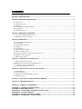
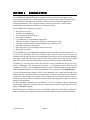
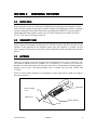
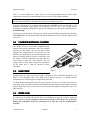
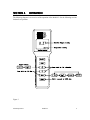
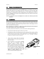
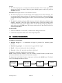
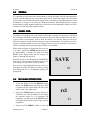
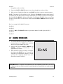
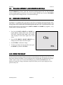
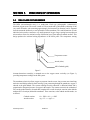
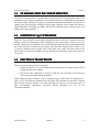
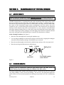
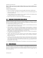
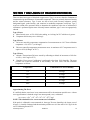
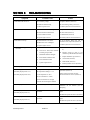
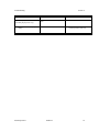
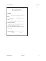
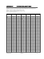
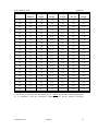
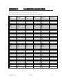
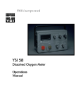
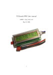
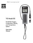
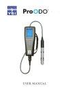
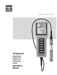
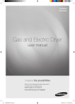
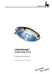
YSI MODEL 95
Handheld
Dissolved Oxygen
And
Temperature System
Operations
Manual
CONTENTS
SECTION 1 INTRODUCTION .........................................................................................................................................1
SECTION 2 PREPARING THE METER ........................................................................................................................2
2.1 UNPACKING .................................................................................................................................................................2
2.2 WARRANTY CARD ......................................................................................................................................................2
2.3 BATTERIES ..................................................................................................................................................................2
2.4 CALIBRATION/STORAGE CHAMBER ............................................................................................................................3
2.5 HAND STRAP ...............................................................................................................................................................3
2.6 THE METER CASE .......................................................................................................................................................3
SECTION 3 PREPARING THE PROBE .........................................................................................................................4
3.1 CHOOSING THE RIGHT MEMBRANE CAP .....................................................................................................................4
3.2 MEMBRANE CAP INSTALLATION .................................................................................................................................4
SECTION 4 OPERATION .................................................................................................................................................6
4.1 TURNING THE INSTRUMENT ON .................................................................................................................................7
4.2 CALIBRATION ..............................................................................................................................................................7
4.3 MAKING MEASUREMENTS ..........................................................................................................................................8
4.4 STIRRING .....................................................................................................................................................................9
4.5 SAVING DATA..............................................................................................................................................................9
4.6 RECALLING STORED DATA..........................................................................................................................................9
4.7 ERASING STORED DATA............................................................................................................................................10
4.8 TOGGLING BETWEEN %-AIR SATURATION AND MG/L...............................................................................................11
4.9 DISSOLVED OXYGEN FILTER .....................................................................................................................................11
4.10 DISPLAY BACKLIGHT ..............................................................................................................................................11
SECTION 5 PRINCIPLES OF OPERATION .............................................................................................................12
5.1 MEA CLARK OXYGEN SENSOR ................................................................................................................................12
5.2 DO READINGS FROM THE CATHODE REDUCTION .....................................................................................................13
5.3 FORMATION OF AGCL AT THE ANODE ......................................................................................................................13
5.4 FUNCTION OF THE ELECTROLYTE .............................................................................................................................13
SECTION 6 MAINTENANCE OF THE MEA SENSOR...........................................................................................14
6.1 ANODE SERVICE........................................................................................................................................................14
6.2 CATHODE SERVICE....................................................................................................................................................14
6.3 DISSOLVED OXYGEN PROBE PRECAUTIONS .............................................................................................................15
6.4 PROBE STORAGE .......................................................................................................................................................15
SECTION 7 DISCUSSION OF MEASUREMENT ERRORS...................................................................................16
SECTION 8 TROUBLESHOOTING............................................................................................................................17
SECTION 9 WARRANTY AND REPAIR ...................................................................................................................19
APPENDIX A - GENERAL SPECIFICATIONS ..........................................................................................................24
APPENDIX B - REQUIRED NOTICE ...........................................................................................................................26
APPENDIX C - ACCESSORIES AND REPLACEMENT PARTS ............................................................................27
APPENDIX D - UNIT CONVERSION ...........................................................................................................................28
APPENDIX E - OXYGEN SOLUBILITY TABLE .......................................................................................................29
APPENDIX F - CALIBRATION VALUES TABLE .....................................................................................................31
i
ii
SECTION 1
INTRODUCTION
The YSI Model 95 Handheld Dissolved Oxygen and Temperature System is a rugged, microprocessor based, digital meter with an attached YSI microelectrode array (MEA) dissolved oxygen
probe. The MEA sensor eliminates the need for stirring in most environmental applications
allowing measurement of DO in the field without an external stirring device. It also reduces
measurement errors caused by insufficient or inconsistent stirring.
The YSI Model 95 has the following features:
•
•
•
•
•
•
•
•
•
•
Microprocessor control
Minimal stirring dependence
Low maintenance MEA DO probe
Push-button calibration
Cap membranes for easy membrane replacement
Simultaneous display of temperature and DO in % air saturation or mg/L
Automatic salinity compensation with manual entering of salinity value
Automatic temperature compensation
Data storage for 50 sets of readings with on screen recall
Waterproof case (IP65)
The YSI Model 95 has a non-detachable, combination sensor available with cable lengths of 10, 25,
50 or 100 feet. The Model 95D has a detachable cable. The probe utilizes easy to install cap
membranes and the probe body has been manufactured with stainless steel to add rugged durability
and sinking weight. The silver anode of the MEA DO sensor requires no servicing for up to 10,000
hours (four years) of operation under normal operating conditions (no sulfite contamination).
The Model 95’s micro-processor allows the system to be easily calibrated with the press of a few
buttons. Additionally, the micro-processor performs a self-diagnostic routine each time the
instrument is turned on. The self-diagnostic routine provides useful information about the function
of the instrument and probe. For a list of these diagnostic codes, see Section 8, Troubleshooting.
A probe calibration/storage chamber is built into the instrument case. A small moist sponge in the
chamber provides a water-saturated air environment that is ideal for air calibration of the dissolved
oxygen probe. This chamber also provides a convenient place to store the probe when the system is
not in use. The Model 95 case is waterproof (rated to IP65) allowing operation in the rain without
damage to the instrument.
Six AA-sized alkaline batteries power the Model 95. A new set of alkaline batteries will provide
approximately 150 hours of continuous operation. When batteries need to be replaced, the LCD will
display a “LO BAT” message.
The YSI Model 95 is designed for use in environmental, aquaculture, and industrial applications
where accurate dissolved oxygen and temperature measurements are desired with minimal stirring.
YSI Incorporated
Model 95
1
SECTION 2
2.1
PREPARING THE METER
UNPACKING
When you unpack your new YSI Model 95 Handheld Dissolved Oxygen and Temperature System
for the first time, compare the packing list with the contents of the shipping box. If there is anything
missing or damaged, call the dealer from whom you purchased the Model 95. If you do not know
which authorized dealers sold the system to you, call YSI Customer Service at 800-765-4974 or
937-767-7241, and we'll be happy to help you.
2.2
WARRANTY CARD
Please complete the Warranty Card and return it to YSI. The warranty card allows the entry of your
purchase of this instrument in our computer system. Once your purchase is recorded, you will
receive prompt, efficient service if any part of your YSI Model 95 needs repair during the warranty
period.
2.3
BATTERIES
There are a few things you must do to prepare your YSI Model 95 for use. First, locate the six AAsized alkaline batteries that were included. Use a screwdriver or a small coin to remove the
thumbscrew on the bottom of the instrument (see figure below). This thumbscrew holds the batterychamber cover in place. The battery-chamber cover is marked with the words "OPEN" and
"CLOSE."
NOTE: On some models, the battery cover thumbscrew may be unscrewed by hand (a screwdriver
may not be required).
Hand strap
Battery chamber
cover
Thumb screw
Polarity marking
O-rings
YSI Incorporated
Model 95
2
Preparing the Meter
Section 2
There is a small molded insert inside each of the two battery-chamber sleeves. These labels
illustrate the correct way to install the batteries into each sleeve of the battery-chamber.
CAUTION: It is very important that the batteries be installed ONLY as illustrated. The instrument
will not function and may be damaged if the batteries are installed incorrectly.
Turn the instrument on by pressing and releasing the ON/OFF button on the front of the
instrument. The liquid crystal display (LCD) should come on. Allow a few seconds for the
instrument to complete its diagnostic routine. If the instrument does not operate, consult Section 8,
Troubleshooting.
You may also want to take the instrument into a dark room and with the instrument ON, hold down
the LIGHT button. The instrument back light should illuminate the LCD so that the display can be
easily read.
2.4
CALIBRATION/STORAGE CHAMBER
The Model 95 has a convenient calibration/storage
chamber built into the instrument’s side. This chamber
provides an ideal storage area for the probe during
transport and extended non-use. If you look into the
chamber, you should notice a small round sponge in the
bottom. Carefully put about 10 drops of clean water into
the sponge. Turn the instrument over and allow any
excess water to drain out of the chamber. The wet
sponge creates a 100% water saturated air environment
for the probe that is ideal for dissolved oxygen
calibration.
2.5
Figure 1
HAND STRAP
The hand strap (see figure on previous page) is designed to allow comfortable operation of the
Model 95 with minimum effort. If the hand strap is adjusted correctly, it is unlikely that the
instrument will be easily dropped or bumped from your hand.
To adjust the hand strap on the back of the meter, unsnap the vinyl cover and pull the two Velcro
strips apart. Place your hand between the meter and the strap and adjust the strap length so that your
hand is snugly held in place. Press the two Velcro strips back together and snap the vinyl cover
back into place.
2.6
METER CASE
The meter case is sealed at the factory and is not intended to be opened, except by authorized
service technicians. Do not attempt to separate the two halves of the meter case as this may
damage the instrument, break the water-proof seal, and may void the manufacturer's
warranty.
YSI Incorporated
Model 95
3
SECTION 3
PREPARING THE PROBE
The YSI Model 95 dissolved oxygen probe is shipped wet with a shipping membrane installed. This
protective membrane cap on the probe tip must be removed and replaced with a new membrane cap
filled with MEA probe solution before using the probe. Follow the instructions below to install the
new membrane cap.
3.1
CHOOSING THE CORRECT MEMBRANE CAP
Two different membrane caps are available for the Model 95. The YSI Model 9501 Membrane Cap
Kit is supplied with the Model 95. This kit contains six 0.5 mil (.0005") membrane caps and a bottle
of MEA probe solution (KCl).
NOTE: YSI 9501 Membrane Caps offer the fastest response to changes in DO and are
recommended by YSI for most applications.
For conditions with low flow or stagnant water, a 1 mil (.001") membrane is available (YSI Model
9502 Membrane Cap Kit). This membrane requires less stirring than the 9501, but has a much
slower response. Use this membrane when minimal stirring (<2"/sec) is available.
3.2
MEMBRANE CAP INSTALLATION
WARNING: Use only YSI MEA probe solution in the membrane cap. Any other solution will
damage the MEA sensor.
To install a new membrane cap on your YSI Model 95 dissolved oxygen probe:
1. Unscrew and remove the probe sensor guard (see Figure 2 ).
2. Unscrew and remove the old membrane cap.
3. Thoroughly rinse the sensor tip with distilled water.
4. Hold the membrane cap and add 8 to 9 drops of MEA probe solution (about half full).
5. Tap the bottom of the cap with your finger a few times to remove any trapped air bubbles.
CAUTION: Do not touch the membrane surface.
6. Screw the membrane cap onto the probe tightly by hand (to prevent leakage of electrolyte). A
small amount of probe solution should overflow.
7. Shake off any excess probe solution and rinse the stainless steel thoroughly with distilled water
to prevent corrosion.
YSI Incorporated
Model 95
4
Preparing the Probe
Section 3
Fill new membrane
cap with 8-9 drops
of MEA probe
solution.
Unscrew guard
Unscrew cap
Screw cap on
tightly by hand
Tap cap with finger
to remove bubbles.
Screw guard on
tightly by hand
Figure 2
WARNING: Use only YSI MEA probe solution in the membrane cap. Any other solution will
damage the MEA sensor.
YSI Incorporated
Model 95
5
SECTION 4
OPERATION
The following diagram is an overview of the operation of the Model 95. See the following sections
for details of operation.
Figure 3
YSI Incorporated
Model 95
6
Operation
4.1
Section 4
TURNING THE INSTRUMENT ON
With the batteries installed correctly, press the ON/OFF button. The instrument will activate all
segments of the display for a few seconds, which will be followed by a self test procedure which
will last for several more seconds. During this power on self test sequence, the instrument’s
microprocessor is verifying that the system is working properly. If the instrument were to detect a
problem, a continuous error message would be displayed. See the section entitled Troubleshooting
for a list of error messages.
NOTE: It is normal for an error to be displayed for a second or two when the system is first
turned on.
4.2
CALIBRATION
Dissolved oxygen calibration must be done in an environment with a known oxygen content. Since
the amount of oxygen in the atmosphere is known, it makes an excellent environment for calibration
(at 100% relative humidity). The calibration/storage chamber contains a moist sponge to create a
100% water saturated air environment.
Before calibrating the YSI Model 95, complete the procedures discussed in the Preparing the
Meter and Preparing the Probe sections of this manual.
To accurately calibrate the YSI Model 95 you will need to know the following information:
•
The approximate altitude of the region in which you are located.
•
The approximate salinity of the samples that you will be measuring. Fresh water has a salinity
of approximately zero. Sea water has a salinity of approximately 35 (parts per thousand, ppt). If
you are not certain what the salinity of the sample water is, use a YSI Model 30 SalinityConductivity-Temperature system to determine it.
1.
Ensure that the sponge inside the instrument's
calibration chamber is wet. Insert the probe into the
calibration chamber.
2. Turn the instrument on by pressing the ON/OFF
button. Wait for the dissolved oxygen and
temperature readings to stabilize (usually 15
minutes is required after turning the instrument on).
If the instrument was already on, press the MODE
button until dissolved oxygen is displayed in mg/L
or % air saturation. To enter the calibration menu,
use two fingers to press and release both the UP
Figure 4
ARROW and DOWN ARROW buttons at the
same time (DOWN ARROW slightly ahead).
YSI Incorporated
Model 95
7
Operation
Section 4
3. The LCD will prompt you to enter the local altitude in hundreds of feet. Use the arrow keys to
increase or decrease the altitude. When the proper altitude appears on the LCD, press the
ENTER button once.
EXAMPLE: Entering the number 12 here indicates 1200 feet.
4. The LCD will prompt you to enter the salinity of the sample(s) that you will be measuring. You
can enter any number from 0 to 80 (ppt). Use the arrow keys to increase or decrease the salinity
setting. When the proper salinity appears on the LCD (zero for fresh water), press the ENTER
button.
5. The Model 95 should now display CAL in the lower left of the display, the calibration value
should be displayed in the lower right of the display and the current DO reading (before
calibration) should be on the main display. Make sure that the DO reading (large display) is
stable, then press the ENTER button. The display should read SAVE then should return to the
Normal Operation Mode.
For best results:
•
Each time the Model 95 is turned off, re-calibrate before taking measurements.
•
Calibrate at a temperature within ±10°C of the sample temperature.
4.3
MAKING MEASURMENTS
The Model 95 has four modes:
Ø Dissolved Oxygen % -- A measurement of oxygen in percent of air saturation (partial
pressure).
Ø Dissolved Oxygen mg/L -- A measurement of oxygen solubility in mg/L.
Ø Recall -- Allows previously stored data to be displayed.
Ø Erase all -- Allows ALL previously stored data to be deleted.
Temperature is displayed in both dissolved oxygen modes.
NOTE: When you turn the Model 95 off, it will “remember” which DO mode you used last and
will return to that mode the next time the instrument is turned on.
To change between the Model 95 modes, simply press and release the MODE button. The Model
95 will cycle through the modes as follows:
Dissolved Oxygen
in % with°C
YSI Incorporated
Dissolved Oxygen
in mg/L with °C
Model 95
Recall
Erase all
8
Operation
4.4
Section 4
STIRRING
It is important to realize that even a small amount of stirring will improve the DO and temperature
response times in stagnant water, because the transfer process of heat and oxygen will be facilitated
by convection. Also, the MEA dissolved oxygen probe is not totally stirring independent due to the
consumption of oxygen at the sensor tip during measurement. When taking dissolved oxygen
measurements in totally stagnant samples, the probe must be moved through the sample at a rate of
2 inches per second to provide adequate stirring.
4.5
SAVING DATA
The Model 95 is equipped with a non-volatile memory that is capable of storing up to 50 different
sets of readings. Non-volatile means that you do not need to worry that your data will be lost due to
a power failure or interruption, such as when the batteries are removed. Each set consists of
dissolved oxygen in percent, dissolved oxygen in mg/L and temperature. The Model 95 will also
assign a site identity number to each set of readings to allow easy review of the data. This feature is
useful in situations where transcribing data is difficult or not available.
While dissolved oxygen is displayed on the screen (in
% or mg/L), depress the ENTER button and hold it
for approximately 2 seconds. The meter will flash
SAVE on the display along with the current site
identity (1 through 50) being used.
When all 50 sites are full, the display will flash FULL
on the screen. This message will remain on the screen
(even after power down) until a button is pushed.
SAVE
Once you have acknowledged the memory is full, any
subsequent saved data will begin overwriting existing
data starting with site #1. No additional warning will
be displayed.
4.6
01
RECALLING STORED DATA
1. To put the Model 95 into the RECALL mode,
depress the MODE button repeatedly until “rcl”
is displayed on the screen along with the site ID
number in the lower right corner.
2. Depress the ENTER button to review the last set
of data that was saved. The Model 95 will display
the dissolved oxygen in % air saturation and
temperature. Another press of the ENTER button
will display the dissolved oxygen in mg/L and the
temperature.
rcl
01
3. Depress the UP ARROW button to move up
YSI Incorporated
Model 95
9
Operation
Section 4
through the saved sets of data.
4. Depress the DOWN ARROW button to move down through the saved sets of data.
5. When you have finished recalling data, press MODE two times to return to normal operation.
NOTE: The Model 95 will recall data as a list. When the UP ARROW is depressed the Model 95
will display the Site ID# for the previously recorded date. For example: If you are reviewing Site
ID# 5 and the UP ARROW is depressed the Model 95 will display Site ID#4. If you are reviewing
Site ID# 5 and Site ID# 5 was the last set of data stored the DOWN ARROW button will display
Site ID# 1.
Here is an example of the Model 95 memory.
Site ID #1
Site ID #2
Site ID #3
If the UP ARROW button was pressed the Model 95 would display Site ID #2
Site ID #4
Site ID #5
4.7
ERASING STORED DATA
1. To erase the data that is stored in the Model 95’s
memory, depress the MODE button until the
Model 95 displays ErAS on the screen.
2. Depress and hold the DOWN ARROW and
ENTER
buttons
simultaneously
for
approximately 5 seconds.
3. When the Model 95 has successfully erased data,
the display reads DONE for 1 to 2 seconds. The
instrument will automatically change to normal
operation after completion and the next saved
data will be stored in site ID# 1.
ErAS
IMPORTANT:
Using the erase function forever and completely erases data in all 50 site
ID’s. Do not use the erase function until all recorded data has been transcribed to an archive outside
the Model 95.
YSI Incorporated
Model 95
10
Operation
4.8
Section 4
TOGGLING BETWEEN %-AIR SATURATION AND MG/L
The UP ARROW key allows quick and convenient switching between the two DO parameters
without going through the instrument’s four modes (using the MODE key). Press the UP ARROW
key to toggle the DO reading between %-air saturation and mg/L.
4.9
DISSOLVED OXYGEN FILTER
The Model 95 is equipped with a DO filter to help filter out instability and high frequency noise.
This feature is useful when measuring dissolved oxygen in an unstable environment such as a fast
moving stream or an aeration tank. The default option for the filter is off. To activate the filter, enter
the filter option menu by pressing both the DOWN ARROW and MODE keys together (Ú key
slightly ahead). Operation procedures:
•
Press both the DOWN ARROW and MODE keys
together (Ú
Ú key slightly ahead). The current status
of the filter is displayed, On or OFF, with a smaller
“FIL” displayed in the bottom right corner of the
screen.
•
Press the UP ARROW or DOWN ARROW key to
change the current status of the filter option.
•
Press ENTER to confirm the change.
•
To abort any changes and exit the filter menu, press
the MODE key (instead of ENTER).
On
FIL
4.10 DISPLAY BACKLIGHT
At times it may be necessary to take measurements with the Model 95 in dark or poorly lit areas. To
help in this situation, the Model 95 comes equipped with a backlight that will illuminate the display
so that it can be easily read. To activate the backlight, press and hold the LIGHT button. The
display will remain lit as long as the button is depressed. When you let it up, the light goes out to
preserve battery life.
YSI Incorporated
Model 95
11
SECTION 5
5.1
PRINCIPLES OF OPERATION
OPERATION
MEA CLARK OXYGEN SENSOR
The MEA (microelectrrode array) is a steady-state Clark type polarographic (voltammetric)
dissolved oxygen sensor. The sensor is made of a silver anode and a gold cathode (consisting of 100
very small electrodes, each measuring approximately 8 micrometers in diameter) and is separated
from the measured medium by a semi-permeable Teflon membrane. The small dimensions of each
individual micro surface consume a very small amount of oxygen. Large spacing between adjacent
microsurfaces allows for minimal overlap of diffusion layers from adjacent cathode surfaces. This
design produces the minimal stirring dependence of the MEA probe. The temperature sensing
Temperature sensor
Anode (silver)
MEA Cathode (gold)
Figure 5
element (thermistor assembly) is mounted next to the oxygen sensor vertically (see Figure 1),
providing temperature readings for the DO system.
The membrane selectively allows oxygen to permeate into the sensor, but prevents most interfering
molecules and fouling materials from entering. Upon permeating through the membrane, oxygen is
reduced at the gold cathode. The current resulting from this reduction is diffusion-limited and is
proportional to the partial pressure of oxygen in the sample. The counter reaction is the oxidation of
silver at the anode/reference electrode that completes the overall electrolytic reaction in the chloride
medium (KCl electrolyte) behind the membrane. These reactions, at the cathode and the anode, are
as follows:
YSI Incorporated
Cathode reaction:
O2 + 2H2O + 4e- ==> 4OH-
Anode reaction:
Ag + Cl- ==> AgCl + e-
Model 95
12
Principals of Operation
5.2
Section 5
DO READINGS FROM THE CATHODE REDUCTION
The oxygen reduction current is sampled and processed, by the meter, and displayed as either %-air
saturation or mg/L. While the parameter of %-air (partial pressure) is independent of temperature
and salinity, mg/L (solubility of oxygen) is a function of temperature and salinity. The same %-air
reading (same partial pressure) would give a higher mg/L reading at a lower temperature than at a
higher temperature. The higher the salinity, the lower the solubility (mg/L) is for the same %-air
reading at the same temperature.
5.3
FORMATION OF AgCl AT THE ANODE
While the oxygen reduction current passes through the internal circuit to be reported as the DO
reading, it also passes through the anode oxidizing the silver and forming a thin layer of silver
chloride. Furthermore, the oxidation of silver at the chloride medium provides a stable potential that
the cathode potential is referenced to (for instance, the polarization potential of the cathode is -1.0
V versus the potential of the Ag/AgCl redox couple at the silver anode). Since the current of the
MEA sensor is so small, there should not be any significant accumulation of AgCl at the anode for
3 to 4 years.
5.4
FUNCTION OF THE ELECTROLYTE
ELECTROLYTE
There are two main functions for the electrolyte:
1. Supply the chloride (Cl-) to the anode/reference electrode for the counter reaction of the
oxygen reduction at the cathode.
2. Provide the ionic conduction of electricity inside the cell, especially in the thin layer
between the gold cathode and the membrane.
Under normal operating conditions, such as measuring oxygen around 100%-air saturation (8.27
mg/L) at 25°C, the electrolyte should last up to 500 hours. This translates into about 62.5 working
days at 8 hours per day operation. The actual electrolyte life, however, may be shorter since, in
most environmental applications, membrane fouling determines the life of the
electrolyte/membrane.
YSI Incorporated
Model 95
13
SECTION 6
6.1
MAINTENANCE OF THE MEA SENSOR
ANODE SERVICE
Warning: Under no circumstances should ammonium hydroxide be used to clean the silver
anode. Ammonium hydroxide will permanently damage the condition of the MEA surface.
The MEA oxygen sensor is, in principle, the same as the conventional Clark oxygen sensor in that
the sensor is made of a silver anode and a gold cathode, but the cathode is a microelectrode array.
Since the current of the MEA oxygen sensor is so much smaller (on average 100 times smaller) than
the current of YSI conventional oxygen sensors, consumption of the silver anode, due to the
formation of AgCl, is minimal during the lifetime of the probe. There should not be any significant
build-up of silver chloride at the surface of the anode for 3 to 4 years, therefore, the anode should
not require chemical cleaning. However, if the surface of the silver anode has become fouled, gently
wet sand it using 400 grit wet/dry sandpaper, rinse thoroughly with deionized or distilled water and
wipe with a wet paper towel until the dark layer is removed. The directions are as follows:
Anode Cleaning Procedures (See figure 6)
ü Rinse the sensor thoroughly after removing the membrane cap.
ü Use wet 400 grit sandpaper to sand away the top layer of the anode by wrapping the sandpaper
around the anode and gently rotating it until the dark layer is removed.
ü Rinse the anode thoroughly with deionized or distilled water and wipe with a wet paper towel.
ü Rinse the anode again with deionized or distilled water.
Anode
Wet
microcloth
Cathode
Buffing Tool
Press lightly against
sensor surface
Figure 6
6.2
CATHODE SERVICE
Warning: Under no circumstances should the gold cathode surface (the MEA surface) be
sanded. Sanding will permanently damage the condition of the MEA surface.
If the MEA oxygen sensor exhibits erratic behavior, such as a current rise at a rate of 1%/hour or
very jumpy readings, it can be serviced by buffing. You can use a few light twists against the
surface with the wet microcloth mounted on the buffing tool provided in the 9503 reconditioning
kit.
YSI Incorporated
Model 95
14
Maintenance of the MEA Sensor
Section 6
Note: The MEA sensor does not require buffing (cleaning) every time the membrane cap is
changed. Under normal operating conditions, the MEA sensor should be buffed no more than two
times per year.
Cathode Cleaning Procedures
ü Remove the membrane cap and rinse the sensor thoroughly with deionized or distilled water.
ü Place the microcloth on the buffing tool (self-adhesive). Wet the microcloth thoroughly with
deionized or distilled water.
ü Twist the buffing tool back and forth three times in opposite directions while lightly pressing
the buffing tool against the sensor surface (see figure 6).
ü Rinse the sensor surface well with deionized or distilled water after buffing.
6.3
DISSOLVED OXYGEN PROBE PRECAUTIONS
Membrane life depends on usage. If the probe is properly maintained, one membrane cap should
last two to four weeks depending on how often the probe is used and the type of samples measured.
It is recommended that membrane caps not be re-used.
1. To keep the electrolyte from drying out, store the probe in a moist environment, such as the
calibration chamber with the wet sponge inside.
2. Erratic readings are a result of loose, wrinkled, damaged, or fouled membranes, or from large
(more than 1/4 of the circumference of the probe) bubbles in the electrolyte reservoir. If erratic
readings or evidence of membrane damage occurs, you should replace the membrane cap and
the KCl solution. The average replacement interval is two to four weeks.
3. If the membrane is coated with oxygen consuming (e.g. bacteria) or oxygen evolving organisms
(e.g. algae), erroneous readings may occur.
4. Chlorine, sulfur dioxide, nitric oxide, and nitrous oxide can affect readings by behaving like
oxygen at the probe. If you suspect erroneous readings, it may be necessary to determine if
these gases are the cause.
5. Avoid any environment that contains substances that may attack the probe materials. Some of
these substances are concentrated acids, caustics, and strong solvents. The probe materials that
come in contact with the sample include FEP Teflon, stainless steel, epoxy, polyetherimide and
the polyurethane cable covering.
6. Do not allow the probe to strike hard objects. The membrane or sensor inside may be damaged.
6.4
PROBE STORAGE
For long term storage (4 weeks), remove the membrane cap, thoroughly rinse the MEA sensor with
deionized or distilled water and install a new membrane cap filled with MEA probe solution. Store
the sensor in a humid environment such as the calibration chamber with the wet sponge inside. Do
NOT store the probe dry.
YSI Incorporated
Model 95
15
SECTION 7 DISCUSSION OF MEASUREMENT ERRORS
There are three basic types of dissolved oxygen errors. Type 1 errors are related to limitations of
instrument design and tolerances of instrument components. These are primarily the meter linearity
and the resistor tolerances. Type 2 errors are due to basic probe accuracy tolerances, mainly
background signal, probe linearity, and variations in membrane temperature coefficient. Type 3
errors are related to the operator's ability to determine the conditions at the time of calibration. If
calibration is performed against more accurately known conditions, type 3 errors are appropriately
reduced.
Type 1 Errors
A. Meter linearity error: ±0.5% of full scale reading, or ±0.04 mg/l at 25°C whichever is greater.
B. Component and circuitry error: ±0.04 mg/l
Type 2 Errors
A. DO errors caused by temperature compensation for measurements at ±10°C from calibration
temperature: ±1% of 25° C (±0.08 mg/l)
B. DO errors caused by temperature measurement errors: A maximum ±0.2°C temperature error is
equal to ±0.5% (0.04mg/L at 25°C).
Type 3 Errors
A. Altitude: The maximum DO error caused by calibrating to altitude in increments of 100 feet:
±0.18% (< 0.015 mg/l at 25°C)
B.
Humidity: Errors occur if calibration is performed at less than 100% humidity. The worst
possible case would be calibration at 0% humidity. The error varies with the calibration
temperature as follows:
Temperature
Calibration Error at 0% humidity
0oC
0.09 mg/l
10oC
0.14 mg/l
20oC
0.21 mg/l
30oC
0.33 mg/l
40oC
0.50 mg/l
Approximating The Error
It is unlikely that the actual error in any measurement will be the maximum possible error. A better
error approximation is obtained using a root mean squared (r.m.s.) calculation:
r.m.s. error = ±[1a2 + 1b2 + 2a2 + 2b2 + 3a2 + 3b2]½ mg/l
NOTE: This calculation is for a near extreme set of conditions.
If the probe is calibrated in water-saturated air, then type 3B errors (humidity), the largest error of
all types, is virtually eliminated and the maximum possible error is in the order of 0.1 mg/L for the
case of calibrating around 25°C.
YSI Incorporated
Model 95
16
SECTION 8
TROUBLESHOOTING
Symptom
1. Instrument will not turn on
2. Instrument will not calibrate
3. Instrument "locks up"
Possible Cause
A. Low battery voltage
A. Replace batteries (Section 2)
B. Batteries installed wrong
B. Check battery polarity. (Section 2)
C. Meter requires service
C. Return system for service (Section 9)
A. Membrane is fouled or damaged
A. Replace membrane cap (Section 3)
B. Probe anode is fouled or dark
B. Clean anode (Section 6)
C. Probe cathode is fouled
C. Buff cathode (Section 6)
D. System requires service
D. Return system for service (Section 9)
A. Instrument has rec'd a shock
A & B. Remove battery lid, wait 15
seconds for reset, replace lid. (Section 2)
B. Batteries are low or damaged
C. System requires service
4. Dissolved Oxygen readings are
inaccurate
Action
C. Return system for service (Section 9)
A.
Cal altitude is incorrect
A.
B.
Probe not in 100% water saturated
air during Cal procedure
Recalibrate w/correct value (Section
4)
B.
Moisten sponge & place in Cal
chamber w/ probe & Recal (Section 4)
C.
Replace membrane cap (Section 3)
D.
Clean anode (Section 6)
E.
Buff cathode (Section 6)
F.
Return system for service (Section 9)
C.
Membrane fouled or damaged
D.
Probe anode is fouled or dark
E.
Probe cathode is fouled
F.
System requires service
5. LCD displays "LO BAT"
A. Batteries are low or damaged
A. Replace batteries (Section 2)
6. Main Display reads “OVEr”
A. Temperature reading is >45°C
(Secondary display reads “ovr”)
B. Temperature reading is <-5°C
In all cases, check calibration values and
procedures. (Section 4)
(Secondary display reads “udr”)
C. DO temperature is >45°C
If each of these were done correctly,
return instrument for service. (Section 9)
D. DO % saturation is >500%
E. DO concentration is >50 mg/L
F. Probe current too high to calibrate
7. Main display reads “PErr”
A. Incorrect sequence of keystrokes.
A. Refer to manual section for step by step
instruction for the function you are
attempting.
8. Main display reads “Err”
A. System has failed its RAM test check
procedure.
A. Turn instrument OFF and back ON
again.
(Secondary display reads “ra”)
B. Return the system for service (Section 9)
9. Main display reads “Err”
(Secondary display reads “ro”)
A. System has failed its ROM test check
procedure.
A.Turn instrument OFF and back ON
again.
B. Return the system for service (Section 9)
YSI Incorporated
Model 95
17
Troubleshooting
Section 8
10. Main reads “Undr”
Probe current too low to calibrate
10. Main display reads “FAIL”
A. EEPROM has failed to respond in
time.
A. Return the system for service (Section 9)
A. Meter is in recall mode.
A.
(Secondary display reads “eep”)
11. Readings on main display don’t
change
YSI Incorporated
Model 95
Press MODE button to return to
Normal Operation (Section 4)
18
SECTION 9
WARRANTY AND REPAIR
YSI Model 95 Dissolved Oxygen Meters are warranted for two years from date of purchase by the
end user against defects in materials and workmanship. YSI Model 95 probes and cables are
warranted for one year from date of purchase by the end user against defects in material and
workmanship. Within the warranty period, YSI will repair or replace, at its sole discretion, free of
charge, any product that YSI determines to be covered by this warranty.
To exercise this warranty, write or call your local YSI representative, or contact YSI Customer
Service in Yellow Springs, Ohio. Send the product and proof of purchase, transportation prepaid, to
the Authorized Service Center selected by YSI. Repair or replacement will be made and the product
returned, transportation prepaid. Repaired or replaced products are warranted for the balance of the
original warranty period, or at least 90 days from date of repair or replacement.
Limitation of Warranty
This Warranty does not apply to any YSI product damage or failure caused by (i) failure to install,
operate or use the product in accordance with YSI’s written instructions, (ii) abuse or misuse of the
product, (iii) failure to maintain the product in accordance with YSI’s written instructions or
standard industry procedure, (iv) any improper repairs to the product, (v) use by you of defective or
improper components or parts in servicing or repairing the product, or (vi) modification of the
product in any way not expressly authorized by YSI.
THIS WARRANTY IS IN LIEU OF ALL OTHER WARRANTIES, EXPRESSED OR IMPLIED,
INCLUDING ANY WARRANTY OF MERCHANTABILITY OR FITNESS FOR A
PARTICULAR PURPOSE. YSI’s LIABILITY UNDER THIS WARRANTY IS LIMITED TO
REPAIR OR REPLACEMENT OF THE PRODUCT, AND THIS SHALL BE YOUR SOLE AND
EXCLUSIVE REMEDY FOR ANY DEFECTIVE PRODUCT COVERED BY THIS
WARRANTY. IN NO EVENT SHALL YSI BE LIABLE FOR ANY SPECIAL, INDIRECT,
INCIDENTAL OR CONSEQUENTIAL DAMAGES RESULTING FROM ANY DEFECTIVE
PRODUCT COVERED BY THIS WARRANTY.
YSI,Incorporated
Model 95
19
Warranty and Repair
Section 9
AUTHORIZED U.S. SERVICE CENTERS
North and East Region
YSI Incorporated • Repair Center • 1725 Brannum Lane • Yellow Springs, Ohio • 45387 • Phone:
(800) 765-4974 • (937) 767-7241• E-Mail: [email protected]
YSI Incorporated
Model 95
20
Warranty and Repair
Section 9
INTERNATIONAL SERVICE CENTERS
YSI Incorporated • Repair Center • 1725 Brannum Lane • Yellow Springs, Ohio • 45387 • Phone:
(937) 767-7241• E-Mail: [email protected]
SPECIALTY SERVICE CENTERS
YSI Incorporated
Model 95
21
Warranty and Repair
Section 9
CLEANING INSTRUCTIONS
NOTE: Before they can be serviced, equipment exposed to biological, radioactive, or toxic
materials must be cleaned and disinfected. Biological contamination is presumed for any
instrument, probe, or other device that has been used with body fluids or tissues, or with waste
water. Radioactive contamination is presumed for any instrument, probe or other device that has
been used near any radioactive source.
If an instrument, probe, or other part is returned or presented for service without a Cleaning
Certificate, and if in our opinion it represents a potential biological or radioactive hazard, our
service personnel reserve the right to withhold service until appropriate cleaning, decontamination,
and certification has been completed. We will contact the sender for instructions as to the
disposition of the equipment. Disposition costs will be the responsibility of the sender.
When service is required, either at the user's facility or at YSI, the following steps must be taken to
insure the safety of our service personnel.
1. In a manner appropriate to each device, decontaminate all exposed surfaces, including any
containers. 70% isopropyl alcohol or a solution of 1/4 cup bleach to 1 gallon tap water are
suitable for most disinfecting. Instruments used with waste water may be disinfected with .5%
Lysol if this is more convenient to the user.
2. The user shall take normal precautions to prevent radioactive contamination and must use
appropriate decontamination procedures should exposure occur.
3. If exposure has occurred, the customer must certify that decontamination has been
accomplished and that no radioactivity is detectable by survey equipment.
4. Any product being returned to the YSI Repair Center, should be packed securely to prevent
damage.
5. Cleaning must be completed and certified on any product before returning it to YSI.
PACKING INSTRUCTIONS
1. Clean and decontaminate items to insure the safety of the handler.
2. Complete and include the Cleaning Certificate.
3. Place the product in a plastic bag to keep out dirt and packing material.
4. Use a large carton, preferably the original, and surround the product completely with packing
material.
5. Insure for the replacement value of the product.
YSI Incorporated
Model 95
22
Warranty and Repair
Section 9
Cleaning Certificate
Organization ________________________________
Department _________________________________
Address ___________________________________
City _______________ State ______ Zip ________
Country __________________
Model No. of Device ______ Lot Number _________
Contaminant (if known) _____________________
Cleaning Agent(s) used _____________________
Radioactive Decontamination Certified?
(Answer only if there has been radioactive exposure)
___ Yes ___ No
Cleaning Certified By _________________________
Name
YSI Incorporated
Date
Model 95
23
APPENDIX A GENERAL SPECIFICATIONS
Materials: ABS, Stainless Steel, and other materials
Dimensions:
Height:
9.5 inches
(24.13 cm)
Thickness:
2.2 inches
(5.6 cm)
Width:
3.5 inches max.
(8.89 cm)
Weight:
1.7 pounds (w/ 10’ cable)
(.77 kg)
Display:
2.3”W x 1.5”L
(5.8 cm W x 3.8 cm L)
Power: 6 AA-size Alkaline Batteries (included)
Approximately 150 hours operation from each new set of batteries
Automatic shutoff after 4 hours without a key press
Water Tightness: Meets or exceeds IP65 standards
Operating Environment
Medium: fresh, sea, or polluted water and most other liquid solutions.
Temperature: -5 to +45 °C
Depth: 0 to 10, 0 to 25, 0 to 50, or 0 to 100 feet (depending on cable length)
Storage Temperature: -5 to +55 °C
System Performance Specifications:
Measurement
Range
Resolution
Accuracy
Temperature
-5 to +45 °C
0.1 °C
± 0.2 °C
Dissolved Oxygen
0 to 500 % Air Sat.
0.1% Air Saturation
0 to 50 mg/L
0.01 mg/L
± 2% or ± 0.2 mg/L,
whichever is greater. 0 to
200% air.
+ 5% for 200% to 500% air
DO Response Time:
Application dependent. Typically 60 sec for 95% of the
change at 25°C
Temperature Response Time:
Typically 95% of the change
Temperature Compensation:
Automatic
YSI Incorporated
Model 95
24
Salinity Compensation Range:
0 to 80 ppt (compensation between 40 and 80 is based on
extrapolation)
Stirring Dependence:
0.5-mil membrane: <5% error in stagnant water or <2% at a
flow rate of 2 in/sec at 120 nA nominal current
1-mil membrane: <3% error in stagnant water or <1% at a
flow rate of 2 in/sec at 100 nA nominal current
Data Storage:
YSI Incorporated
50 points with ID number.
Model 95
25
APPENDIX B
REQUIRED NOTICE
The Federal Communications Commission defines this product as a computing device and requires
the following notice:
This equipment generates and uses radio frequency energy and if not installed and used properly,
may cause interference to radio and television reception. There is no guarantee that interference will
not occur in a particular installation. If this equipment does cause interference to radio or television
reception, which can be determined by turning the equipment off and on, the user is encouraged to
try to correct the interference by one or more of the following measures:
•
re-orient the receiving antenna
•
relocate the computer with respect to the receiver
•
move the computer away from the receiver
•
plug the computer into a different outlet so that the computer and receiver are on
different branch circuits.
If necessary, the user should consult the dealer or an experienced radio/television technician for
additional suggestions. The user may find the following booklet, prepared by the Federal
Communications Commission, helpful: "How to Identify and Resolve Radio-TV Interference
Problems." This booklet is available from the U.S. Government Printing Office, Washington, DC
20402, Stock No. 0004-000-00345-4.
YSI Incorporated
Model 95
26
APPENDIX C ACCESSORIES AND REPLACEMENT PARTS
The following parts and accessories are available from YSI or any Franchise Dealer authorized by
YSI.
YSI Order Number
Description
9501
Replacement Membrane Cap Kit, 0.5 mil ( 6 each )
9502
Replacement Membrane Cap Kit, 1 mil ( 6 each )
9503
MEA Probe Reconditioning Kit
5520
Carrying Case, small (95-10 or 95-25 only)
5050
Carrying Case, medium (95-50 or 95-100)
059965
Replacement Probe & Cable Assembly (10 feet)
059981
Replacement Probe & Cable Assembly (25 feet)
059984
Replacement Probe & Cable Assembly (50 feet)
059987
Replacement Probe and Cable Assembly (100 feet)
059971
Replacement Front Case Cover
055242
Replacement Rear Case Cover
055244
Replacement Battery Cover Kit
055204
Replacement Case Gasket and Screw
055219
Calibration Chamber Sponge
030157
Main Board Assembly
YSI Incorporated
Model 95
27
APPENDIX D UNIT CONVERSION
Conversion Chart
To Convert From
To
Equation
Feet
Meters
Multiply by 0.3048
Meters
Feet
Multiply by 3.2808399
Degrees Celsius
Degrees Fahrenheit
(9/5
Degrees Fahrenheit
Degrees Celsius
5/9 (oF-32)
Milligrams per liter (mg/l)
Parts per million (ppm)
Multiply by 1
YSI Incorporated
Model 95
o
C)+32
28
APPENDIX E
OXYGEN SOLUBILITY TABLE
Solubility of Oxygen in mg/l in Water Exposed to Water-Saturated Air at 760 mm Hg Pressure.
Salinity = Measure of quantity of dissolved salts in water.
Chlorinity = Measure of chloride content, by mass, of water.
S(0/00) = 1.80655 x Chlorinity (0/00)
Chlorinity:0
5.0 ppt
10.0 ppt
15.0 ppt
20.0 ppt
25.0 ppt
C
Salinity:0
9.0 ppt
18.1 ppt
27.1 ppt
36.1 ppt
45.2 ppt
0.0
14.62
13.73
12.89
12.10
11.36
10.66
1.0
14.22
13.36
11.78
11.07
10.39
2.0
13.83
13.00
12.22
11.48
10.79
10.14
3.0
13.46
12.66
11.91
11.20
10.53
9.90
4.0
13.11
12.34
11.61
10.92
10.27
9.66
5.0
12.77
12.02
11.32
10.66
10.03
9.44
6.0
12.45
11.73
11.05
10.40
9.80
9.23
7.0
12.14
11.44
10.78
10.16
9.58
9.02
8.0
11.84
11.17
10.53
9.93
9.36
8.83
9.0
11.56
10.91
10.29
9.71
9.16
8.64
10.0
11.29
10.66
10.06
9.49
8.96
8.45
11.0
11.03
10.42
9.84
9.29
8.77
8.28
12.0
10.78
10.18
9.62
9.09
8.59
8.11
13.0
10.54
9.96
9.42
8.90
8.41
7.95
14.0
10.31
9.75
9.22
8.72
8.24
7.79
15.0
10.08
9.54
9.03
8.54
8.08
7.64
16.0
9.87
9.34
8.84
8.37
7.92
7.50
17.0
9.67
9.15
8.67
8.21
7.77
7.36
18.0
9.47
8.97
8.50
8.05
7.62
7.22
19.0
9.28
8.79
8.33
7.90
7.48
7.09
20.0
9.09
8.62
8.17
7.75
7.35
6.96
21.0
8.92
8.46
8.02
7.61
7.21
6.84
22.0
8.74
8.30
7.87
7.47
7.09
6.72
23.0
8.58
8.14
7.73
7.34
6.96
6.61
Temp
o
YSI Incorporated
12.55
Model 95
29
Oxygen Solubility Table
Temp
Appendix E
Chlorinity:0
5.0 ppt
10.0 ppt
15.0 ppt
20.0 ppt
25.0 ppt
Salinity:0
9.0 ppt
18.1 ppt
27.1 ppt
36.1 ppt
45.2 ppt
24.0
8.42
7.99
7.59
7.21
6.84
6.50
25.0
8.26
7.85
7.46
7.08
6.72
6.39
26.0
8.11
7.71
7.33
6.96
6.62
6.28
27.0
7.97
7.58
7.20
6.85
6.51
6.18
28.0
7.83
7.44
7.08
6.73
6.40
6.09
29.0
7.69
7.32
6.96
6.62
6.30
5.99
30.0
7.56
7.19
6.85
6.51
6.20
5.90
31.0
7.43
7.07
6.73
6.41
6.10
5.81
32.0
7.31
6.96
6.62
6.31
6.01
5.72
33.0
7.18
6.84
6.52
6.21
5.91
5.63
34.0
7.07
6.73
6.42
6.11
5.82
5.55
35.0
6.95
6.62
6.31
6.02
5.73
5.46
36.0
6.84
3.52
6.22
5.93
5.65
5.38
37.0
6.73
6.42
6.12
5.84
5.56
5.31
38.0
6.62
6.32
6.03
5.75
5.48
5.23
39.0
6.52
6.22
5.98
5.66
5.40
5.15
40.0
6.41
6.12
5.84
5.58
5.32
5.08
41.0
6.31
6.03
5.75
5.49
5.24
5.01
42.0
6.21
5.93
5.67
5.41
5.17
4.93
43.0
6.12
5.84
5.58
5.33
5.09
4.86
44.0
6.02
5.75
5.50
5.25
5.02
4.79
45.0
5.93
5.67
5.41
5.17
4.94
4.72
o
C
* This table is provided for your information only. It is NOT required when calibrating the Model
95 in accordance with the instructions outlined in the section entitled Calibration
YSI Incorporated
Model 95
30
APPENDIX F
CALIBRATION VALUES TABLE
Calibration values for various atmospheric pressures and altitudes.
Note: This table is for your information only. It is not required for calibration.
Pressure Inches Pressure
of Hg
mm Hg
30.23
768
29.92
760
29.61
752
29.33
745
29.02
737
28.74
730
28.43
722
28.11
714
27.83
707
27.52
699
27.24
692
26.93
684
26.61
676
26.34
669
26.02
661
25.75
654
25.43
646
25.12
638
24.84
631
24.53
623
24.25
616
23.94
608
23.62
600
23.35
593
23.03
585
22.76
578
22.44
570
22.13
562
21.85
555
21.54
547
21.26
540
20.94
532
20.63
524
20.35
517
YSI Incorporated
Pressure
kPA
102.3
101.3
100.3
99.3
98.3
97.3
96.3
95.2
94.2
93.2
92.2
91.2
90.2
89.2
88.2
87.1
86.1
85.1
84.1
83.1
82.1
81.1
80.0
79.0
78.0
77.0
76.0
75.0
74.0
73.0
71.9
70.9
69.9
68.9
Altitude
in feet
-276
0
278
558
841
1126
1413
1703
1995
2290
2587
2887
3190
3496
3804
4115
4430
4747
5067
5391
5717
6047
6381
6717
7058
7401
7749
8100
8455
8815
9178
9545
9917
10293
Model 95
Altitude
in meters
-84
0
85
170
256
343
431
519
608
698
789
880
972
1066
1160
1254
1350
1447
1544
1643
1743
1843
1945
2047
2151
2256
2362
2469
2577
2687
2797
2909
3023
3137
Calibration
Value in %
101
100
99
98
97
96
95
94
93
92
91
90
89
88
87
86
85
84
83
82
81
80
79
78
77
76
75
74
73
72
71
70
69
68
31
1700/1725 Brannum Lane
Yellow Springs, Ohio 45387 USA
(800) 765-4974 (937) 767-7241
FAX: (937) 767-9320
Website: http://www.ysi.com
E-MAIL: [email protected]
ITEM # 059976
DRW # A59976D
October 1998