1
GE Fanuc Automation
Programmable Control Products
VersaMax® PLC
Station Manager
User's Manual
GFK-1876
April 2001
GFL-002
Warnings, Cautions, and Notes
as Used in this Publication
Warning
Warning notices are used in this publication to emphasize that hazardous
voltages, currents, temperatures, or other conditions that could cause
personal injury exist in this equipment or may be associated with its use.
In situations where inattention could cause either personal injury or
damage to equipment, a Warning notice is used.
Caution
Caution notices are used where equipment might be damaged if care is not
taken.
Note
Notes merely call attention to information that is especially significant to
understanding and operating the equipment.
This document is based on information available at the time of its publication. While efforts have
been made to be accurate, the information contained herein does not purport to cover all details or
variations in hardware or software, nor to provide for every possible contingency in connection
with installation, operation, or maintenance. Features may be described herein which are not
present in all hardware and software systems. GE Fanuc Automation assumes no obligation of
notice to holders of this document with respect to changes subsequently made.
GE Fanuc Automation makes no representation or warranty, expressed, implied, or statutory with
respect to, and assumes no responsibility for the accuracy, completeness, sufficiency, or usefulness of
the information contained herein. No warranties of merchantability or fitness for purpose shall apply.
The following are trademarks of GE Fanuc Automation North America, Inc.
Alarm Master
CIMPLICITY
CIMPLICITY 90–ADS
CIMSTAR
Field Control
GEnet
Genius
Helpmate
Logicmaster
Modelmaster
Motion Mate
PowerMotion
PowerTRAC
ProLoop
PROMACRO
Series Five
Series 90
Series One
Series Six
Series Three
VersaMax
VersaPro
VuMaster
Workmaster
©Copyright 2001 GE Fanuc Automation North America, Inc.
All Rights Reserved
Contents
Chapter 1
Overview................................................................................................. 1-1
Using the Station Manager Functions................................................................... 1-2
Local and Remote Operation of the Station Manager ........................................... 1-2
Monitor and Modify Commands.......................................................................... 1-3
Contents of this Manual....................................................................................... 1-4
Related VersaMax Documents............................................................................. 1-5
Chapter 2
Getting Started ....................................................................................... 2-1
Connecting a Terminal for the Local Station Manager.......................................... 2-2
Configuring the CPU for Local Station Manager Operation.................................. 2-4
Controlling Local Station Manager Operation on Port 1 ....................................... 2-5
Using the Station Manager .................................................................................. 2-7
Station Manager Display Format ......................................................................... 2-9
Checking the Ethernet Interface IP Address ....................................................... 2-10
Testing Communications on the Network .......................................................... 2-11
Chapter 3
Station Manager Command Summary.................................................. 3-1
Commands to Display/Control PLC Features ....................................................... 3-2
Commands to Display/Control Station Manager Operation .................................. 3-2
Commands to Display/Control the Ethernet Interface Setup ................................. 3-3
Commands to Display/Control Ethernet Interface Operation ................................ 3-3
Commands to Display/Control Network Activities............................................... 3-4
Commands to Display Ethernet Status Information .............................................. 3-4
Chapter 4
Station Manager Command Reference ................................................. 4-1
Chapter 5
Tallies of Ethernet Tasks........................................................................ 5-1
Tally Groups ....................................................................................................... 5-2
Viewing and Clearing Tallies .............................................................................. 5-3
Tally Definitions ................................................................................................. 5-4
Chapter 6
Exception Events .................................................................................... 6-1
Viewing and Clearing the Exception Log............................................................. 6-2
Reading an Exception Log Entry using the Station Manager ................................ 6-3
Reading Ethernet Exceptions in the PLC Fault Table ......................................... 6-11
Exception Log Event Descriptions..................................................................... 6-12
GFK-1876
iii
Overview
Chapter
1
The Station Manager is a part of the communications software in VersaMax® PLC
IC200CPUE05.
The Station Manager can be used to:
Observe and modify internal statistics, an exception log, and advanced user
parameters.
Interrogate and control the Ethernet interface. Password security prevents
unauthorized use of commands that change the Ethernet interface parameters or
states.
You can use the Station Manager to monitor the operation of the Ethernet interface
itself, and of its operation on the network. If a problem occurs, the Station Manager
may be used to pinpoint the source.
The Station Manager functions operate in background mode. The Station Manager
is not available during power–up diagnostics or when using the Software Loader.
GFK-1876
1-1
1
Using the Station Manager Functions
The Station Manager functions are a group of commands that can be sent to the
Ethernet interface. These commands can be used to monitor and control the
operation of the Ethernet interface. For example, the Station Manager can display
Port 1 status, display the Ethernet configuration, and display the Advanced User
Parameters. It can also force the Ethernet interface to be online or offline, restart the
Ethernet interface firmware, and display counters and exception events.
The operator interface to the Station Manager can be either a terminal emulator on a
personal computer, or an ASCII terminal. This device can be connected directly to
the VersaMax PLC CPUE05, or connected to another device on the network, as
explained below.
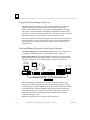
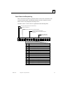
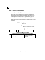
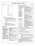
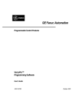
Local and Remote Operation of the Station Manager
Local Station Manager: the Station Manager functions can be accessed directly by
connecting the terminal emulator or ASCII terminal to Port 1 on the CPU.
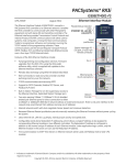
Remote Station Manager. the Station Manager functions can be accessed over the
Ethernet network from another Ethernet interface. Similarly, the Station Manager
function in CPUE05 can access another interface remotely over the network.
Host Computer or
Control Device Running
a Host Communications
Toolkit Application
Local
Station
Manager
REMOTE
LOCAL
VersaMax PLC with
CPUE05
VersaMax PLC with
CPUE05
Series 90-70 PLC with
Ethernet Interface
Programmer Software
runninng on a PC
Series 90-30 PLC with
Ethernet Interface
Ethernet Cable
Hub
The Station Manager commands can be invoked over the network from other
VersaMax PLC Ethernet interfaces or Series 90 PLC Ethernet Interfaces. When
invoked remotely, the Station Manager software processes the command as if it had
been entered locally. The Station Manager automatically directs output from the
command back over the network to the device that sent the request. There is no
indication on the local Station Manager terminal (if attached) when a remote
command is being processed.
Both the local and remote access share the same security level.
1-2
VersaMax® PLC Station Manager User's Manual – April 2001
GFK-1876
1
Monitor and Modify Commands
There are two types of Station Manager commands:
Monitor commands and
Modify commands.
Both Monitor and Modify-level commands can be used either locally or remotely.
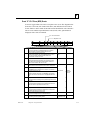
Monitor Commands
Monitor commands provide information about the Ethernet interface and the
network. Executing these commands does not affect the operation of the Ethernet
interface. They are available to anyone using the Station Manager. The Monitor
commands are:
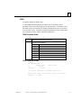
Command
help
log
login
ltime
node
parm
Function Performed
Display Station Manager
command set
Display current exception log
Enter privileged access level
Display login inactivity
timeout
Display basic identification
Display advanced user
parameters
Command
port1
Function Performed
Display Port 1 status
prog
Display PLC logic program
name
Display Ethernet configuration
Display various operating
status
Display various operating
counters
Display internal Ethernet clock
sosw
stat
tally
time
xchange
Display individual Ethernet
Global Data exchange
information
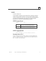
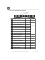
Modify Commands
Modify commands perform functions that may change the operation of the Ethernet
interface. Access to Modify commands is password-protected. The Modify
commands are:
Command
chltime
chparm
chport1
chsosw
chtime
clear
killss
logout
GFK-1876
Function Performed
Change login inactivity timeout
Change the backup Advanced
User Parameters
Toggle Port 1 override
Change the backup Ethernet
configuration
Change the internal Ethernet
clock
Clear selected status
information
Delete an SRTP connection
Exit privileged access level
Chapter 1 Overview
Command
net
ok
restart
Function Performed
Force network offline/online
Reset the STAT LED (log isn’t
cleared)
Send ICMP Echo requests
Send command to remote
node
Display current or most recent
ping results
Restart the Ethernet firmware
stopp
trace
Stop ping in progress
Display activity for debug
ping
rem
repp
1-3
1
Contents of this Manual
Chapter 1, Overview. Chapter 1 describes the Station Manager.
Chapter 2, Getting Started. Chapter 2 gives basic installation and startup. This
chapter gives basic installation and startup information for using the Station
Manager:
Connecting a terminal for the Local Station Manager
Configuring the CPU for Local Station Manager Operation
Controlling Local Station Manager Operation on Port 1
Using the Station Manager
Station Manager Display Format
Checking the Ethernet Interface IP Address
Testing Communications on the Network
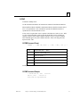
Chapter 3, Station Manager Command Summary. Chapter 3 is a task-oriented
guide to using the Station Manager commands. Detailed definitions of all Station
Manager commands are in chapter 4.
Commands to Display and Control PLC Features
Commands to Display and Control Station Manager Operation
Commands to Display and Control the Ethernet Interface Setup
Commands to Display and Control Ethernet Interface Operation
Commands to Display and Control Network Activities
Commands to Display Ethernet Status Information
Chapter 4, Station Manager Command Reference. This chapter is an
alphabetically-organized reference to the Station Manager commands. It explains
how to execute each command and interpret its results.
Chapter 5, Tallies of Ethernet Tasks. Chapter 5 explains how to view tallies of
specific Ethernet tasks. It also describes the types of information you can display,
grouped by task. Contents of this chapter are:
Tally Groups
Viewing and Clearing Tallies
Tally Definitions
Chapter 6, Exception Events. Chapter 6 explains how to view information about
“exceptional” Ethernet events. Contents of this chapter are:
Viewing and Clearing the Exception Log
Reading an Exception Log Entry using the Station Manager
Reading Exceptions in the PLC Fault Table
Exception Log Event Descriptions
1-4
VersaMax® PLC Station Manager User's Manual – April 2001
GFK-1876
1
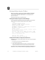
Related VersaMax Documents
Refer to the documents below if you need more information about the VersaMax
PLC and related products.
GFK-1876
VersaMax PLC User’s Manual
(catalog number GFK-1503, revision
C or later)
Describes the installation, operation, and
programming instruction set of VersaMax family
of PLC CPUs.
VersaMax Ethernet Network Interface
Unit User’s Manual (catalog number
GFK-1860)
Describes the installation and operation of the
Ethernet Network Interface Unit module.
VersaMax Modules, Power Supplies,
and Carriers User’s Manual (catalog
number GFK-1504)
Describes the many VersaMax I/O and option
modules, power supplies, and carriers. This
manual also provides detailed system
installation instructions.
Chapter 1 Overview
1-5
Getting Started
Chapter
2
This chapter gives basic installation and startup information for using the Station
Manager with the VersaMax® PLC IC200CPUE05.
This chapter includes:
GFK-1876
Connecting a terminal for the Local Station Manager
Configuring the CPU for Local Station Manager Operation
Controlling Local Station Manager Operation on Port 1
Using the Station Manager
Station Manager Display Format
Checking the Ethernet Interface IP Address
Testing Communications on the Network
2-1
2
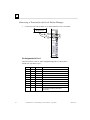
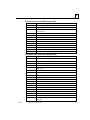
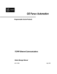
Connecting a Terminal for the Local Station Manager
1.
Connect the serial cable from the PC or ASCII terminal to Port 1 of CPUE05.
Connect Local Station
Manager to Port 1
PORT 1
1
6
9
5
RS232
PORT 2
RS485
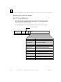
Pin Assignments for Port 1
The pinout of Port 1 allows a simple straight-through cable to connect with a
standard AT-style RS-232 port.
2-2
Pin
Signal
1
n/c
Direction
Function
2
3
TXD
Output
Transmit Data output
RXD
Input
Receive Data input
4
n/c
5
GND
6
n/c
--
0V/GND signal reference
7
CTS
Input
Clear to Send input
8
RTS
Output
Request to Send output
9
n/c
Shell
SHLD
--
Cable Shield wire connection / 100%
(Continuous) shielding cable shield
connection
VersaMax® PLC Station Manager User's Manual – April 2001
GFK-1876
2
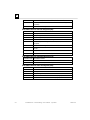
Cable for Local Station Manager Connection
The maximum cable length is 15 meters (50ft).
1
1
6
6
2
2
3
3
4
4
5
5
7
7
8
9
8
9
PC 9-Pin
Serial Port
9-pin female
CPU
Port 1
9-pin male
(2) RXD
(3) TXD
(5) GND
(7) RTS
(8) CTS
(2) TXD
(3) RXD
(5) GND
(7) CTS
(8) RTS
The shield must connect to
shell of connectors on both
ends of the cable.
Vendor Part numbers below are provided for reference only. Any part that meets
the same specification can be used.
Cable:
Belden
9610
9 Pin Male
Connector:
Connector
Shell:
GFK-1876
Computer cable, overall braid over foil shield
5 conductor †
30 Volt / 80°C (176°F)
24 AWG tinned copper, 7x32 stranding
Vendor:
Plug:
Type:
Pin:
ITT/Cannon
Crimp
DEA9PK87F0
030-2487-017
AMP
205204-1
66506-9
Solder
ITT/Cannon
ZDE9P
-AMP
747904-2
-Kit *– ITT Cannon DE121073-54 [9-pin size backshell kit]:
Metal-Plated Plastic (Plastic with Nickel over Copper) †
Cable Grounding Clamp (included)
40° cable exit design to maintain low-profile installation
Plus – ITT Cannon 250-8501-010 [Extended Jackscrew]:
Threaded with #4-40 for secure attachment to CPU001 port †
Order Qty 2 for each cable shell ordered
†
Critical Information – any other part selected should meet or exceed this criteria.
*
Use of this kit maintains the 70mm installed depth.
Chapter 2 Getting Started
2-3
2
Configuring the CPU for Local Station Manager Operation
Port 1 must be configured for or forced to Local Station Manager operation before
the function can be used. This can be done from the programmer, by pressing the
Ethernet Restart pushbutton, or by sending the REM CHPORT1 command.
You will also need to set up the communication parameters of the terminal emulator
or ASCII terminal that is being used to run the Station Manager so that they match
the configuration of Port 1.
Configuring Port 1 of the CPU for Local Station Manager Operation
Port configuration for using the Local Station Manager function is part of the
overall CPU setup, which is described in the VersaMax PLC User’s Manual (GFK1503, revision C or later).
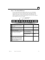
Specific parameters for Port 1 that must be set up for Local Station Manager
operation are listed below.
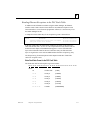
Feature
Choices
Port Mode
SNP
Local Station Manager, SNP, Serial I/O,
RTU, Disabled
Parity
When Port Mode is configured as
Local Station Manager, default is
None.
In Local Station Manager mode:
9600
In Local Station Manager mode:
Odd, Even, None
Data Rate (bps)
Flow Control
2-4
Default
None
In Local Station Manager mode:
1200, 2400, 4800, 9600, 19200, 38400,
57600, 115200
In Local Station Manager mode:
Hardware, None
VersaMax® PLC Station Manager User's Manual – April 2001
GFK-1876
2
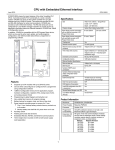
Controlling Local Station Manager Operation on Port 1
PORT 1
RS232
PORT 2
RS485
As part of the CPU configuration, Port 1 can be configured for
either CPU serial communications (SNP, RTU, Serial I/O), or
Local Station Manager use. Port 1 can still be forced into Local
Station Manager operation even when it is configured for CPU
use. However, if Port 1 is configured for Local Station Manager
use, that becomes its exclusive mode, and it cannot be used for
CPU functions. Therefore, Port 1 should typically be configured
for CPU use, and forced to Station Manager use when necessary.
If Port 1 has been configured for CPU use: you can place it in
Local Station Manager mode by holding down the Restart
pushbutton for at least 5 seconds (wait for the Port1 LED to
change to amber). Port 1 remains in Local Station Manager mode
until the PLC is power cycled, until the Restart pushbutton is held
down for at least 5 seconds, or until the Ethernet interface is
restarted (via the Restart pushbutton or Restart command).
If Port 1 has been configured for Local Station Manager use:
it cannot be used for CPU serial communications or for firmware
upgrades using Winloader. The Restart pushbutton will NOT
toggle it to the CPU serial protocols.
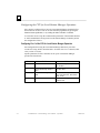
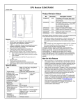
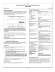
Using the Ethernet Restart Pushbutton
The Ethernet Restart pushbutton is located on the right side of the module.
Ethernet Restart
Pushbutton
ETHERNET
RESTART
GFK-1876
ETHERNET
LAN
10 BASE T /
100 BASE TX
PORT 1
Ethernet
LEDs
STAT
Press the Restart pushbutton for less than 5 seconds if you want to reset the
Ethernet hardware, test the Ethernet LEDs, and restart the Ethernet firmware.
This disrupts any Ethernet communications that are presently underway.
Press the Restart pushbutton until the Port 1 LED becomes amber (at least 5
seconds) if you want to toggle the function of Port 1 between configured CPU
operation and Local Station Manager operation. Note that if Port 1 is forced to
or configured for Local Station Manager operation, Winloader cannot be used
for a firmware upgrade.
Chapter 2 Getting Started
2-5
2
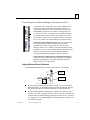
Observing the Ethernet LEDs
The three Ethernet LEDs indicate the status and activity of the Ethernet interface.
LAN
indicates the status and activity of the Ethernet network connection.
ON/flickering green indicates Ethernet interface is online. ON amber
indicates Ethernet interface is offline
STAT
indicates the general status of the Ethernet interface. ON green
indicates no “exception” detected. ON amber indicates an exception.
Blinking amber indicates error code. Blinking green indicates waiting for
configuration or waiting for IP address.
PORT1
indicates when the Ethernet firmware is controlling the RS-232 serial
port. ON amber indicates Port 1 is available for Local Station Manager
use (either by configuration or forcing). OFF indicates PLC CPU is
controlling Port 1.
The Ethernet LEDs turn ON briefly, first amber then green, whenever a restart is
performed by pressing and releasing the Restart pushbutton. This allows you to
verify that the Ethernet LEDs are operational. All three LEDs blink green in unison
when a firmware load is in progress.
Station Manager Operation in Different Ethernet Interface States
The Station Manager is active whenever the Ethernet interface is in the Operational
state (see the VersaMax PLC User’s Manual, GFK-1503). It is also active for local
use only when the Ethernet interface is waiting for an IP address.
The Station Manager is not active during diagnostics, when using the software
loader, or if there is a hardware failure.
2-6
VersaMax® PLC Station Manager User's Manual – April 2001
GFK-1876
2
Using the Station Manager
There are two types of Station Manager commands:
Monitor commands and
Modify commands.
Monitor commands provide information about the Ethernet interface and its
operation on the network. Executing these commands does not affect the operation
of the Ethernet interface. They are available to anyone using the Station Manager.
The Monitor-level command prompt is:
>
Modify commands perform functions that may change the operation of the Ethernet
interface and the network. Access to Modify commands is password-protected. The
Modify-level command prompt is:
=
Both Monitor and Modify-level commands can be used either locally or remotely.
(The REM command cannot be remotely sent to another Ethernet interface).
Entering Commands
Press the Enter key on the PC or ASCII terminal. The Station Manager should
respond with the Station Manager Monitor mode prompt character.
>
You can enter any Monitor commands from this prompt.
To use any of the Modify commands you must obtain the Modify “=” prompt using
the LOGIN command. To log in to Modify mode, type from the “>” prompt:
login
<RET>
The password prompt appears:
Password:
Type in the password and press the Enter key. The password is case sensitive and
may include special characters. The default password is “system” (lower case). If
you want to change the password or if you have forgotten the password, follow the
appropriate procedure under the CHPARM STPASSWD command in Chapter 4,
“Station Manager Command Reference”. If the entered password is correct, the
Modify prompt appears.
=
You can execute all Monitor and Modify commands from the Modify prompt. If no
commands are executed within the default login inactivity timeout (or a different
timeout period that has been set up using the CHLTIME command), the Modify
login expires and you need to login again.
GFK-1876
Chapter 2 Getting Started
2-7
2
Entering Station Manager Commands
Refer to the detailed command descriptions in chapter 4. In the command format
descriptions, brackets and braces indicate optional or alternative parameters for a
command. These brackets and braces are NOT part of a command; do not include
them when entering a command.
Bracket Type
Indicates
< > angle brackets
[ ] square brackets
{|} braces and
vertical bars
Symbolic parameter name
Command
tally
Example Entry
<tasks>
tally
Optional parameter
log [z]
log
Alternative parameters
net { on | off }
net on
c
Enter the rest of the command exactly as it is shown. Do not include extra spaces or
tab characters within commands. All data entered for the command is converted to
lower case unless it is enclosed in double quotes (“ ”).
Entering Control Characters
The Station Manager accepts the ASCII control characters listed below. Other
control characters are ignored.
Control Character
Usual Keyboard Function
BS
DEL
DC1
DC2
DC3
CAN
CR
CTRL–H (Backspace)
Delete
CTRL–Q
CTRL–R
CTRL–S
CTRL–X
Return (Enter)
Function
Delete previous character
Delete previous character
Resume output to the display
Recall previous command line(s)
Stop output to the display
Cancel the current input line
Terminate line and execute command
Entering a Multi-line Command
Use the character pair \<CR> to continue a command on the next line. The
\ (backslash) character is not part of any command.
Repeating a Prior Command Entry
The Station Manager stores up to the last 10 command lines. This stored list is
cleared at restart or power-up. If you want to repeat a command, press CTRL-R as
many times as needed. Press CTRL-X to clear the current Station Manager
command line.
2-8
VersaMax® PLC Station Manager User's Manual – April 2001
GFK-1876
2
Station Manager Display Format
The Station Manager display format depends on the type of data being input or
output.
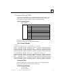
Numeric Values
Most numeric values are displayed as decimal values. In cases where it would be
helpful, the value is displayed in both decimal and hexadecimal. A few values are
displayed only in hexadecimal. Hexadecimal values are displayed with an “H” as
their last character. An example of numeric output is shown below:
ifragtmr = 100 (0064H)
When a numeric value is entered, it may be entered as either a decimal value or as a
hexadecimal value. A hexadecimal value must be entered using the trailing “H”
(either upper or lower case) as its last character.
Byte String Values
Byte strings represent each successive byte as a pair of hexadecimal digits enclosed
in double angle brackets (<<...>>).
MAC Address = <<080019010842>>
IP Addresses
IP addresses are displayed and entered in dotted decimal format:
IP Address = 10.0.0.2
GFK-1876
Chapter 2 Getting Started
2-9
2
Checking the Ethernet Interface IP Address
When you are setting up a system, you can check the IP address of the Ethernet
interface using the Local Station Manager, and also verify that it is unique by
accessing it from another device on the network. It is very important not to
duplicate IP addresses.
Instructions for both checks are summarized below.
Checking the IP Address Using the Local Station Manager
To be certain that the local interface has the correct IP address, access the Station
Manager and issue the NODE command (a Monitor mode command):
> node
IC200CPUE05 Embedded Ethernet
Copyright (c) 2000. All rights reserved.
Version 2.00 (28A1) TCP/IP
Version 2.00 (17A1) Loader
IP Address = 10.0.0.2
Subnet Mask = 255.255.0.0
MAC Address = <<080019010203>>
Gateway = 0.0.0.0
NTP Time Servers (1,2,3) = 0.0.0.0, 0.0.0.0, 0.0.0.0
Station Manager at Port 1:
Data Rate = 9600, Parity = NONE, Flow Control = NONE
Port 1 configured for Station Manager; not overridden
Source of Soft Switches: CPU
August 28, 2001, 16:00:05
Date/time initialized from PLC CPU
Verifying that the IP Address is Unique from Another Device
You should also make sure the Ethernet interface does not have the same IP address
as another node.
1.
Disconnect the LAN cable from the Ethernet interface.
2.
Log into another network device
3.
Use the PING command as described in chapter 4, and ping the IP address
assigned to the Ethernet interface from some other device on the network.
If you get an answer to the ping, it means the chosen IP address is already in use by
another node. You must correct this situation by assigning unique IP addresses.
2-10
VersaMax® PLC Station Manager User's Manual – April 2001
GFK-1876
2
Testing Communications on the Network
During system setup, use the Station Manager to test each installed Ethernet
interface to be sure each interface is operational and configured with proper TCP/IP
parameters. To do that:
1.
Enter the LOGIN command:
login
The LOGIN command is followed by the password prompt:
Password:
The factory default password is:
system (lower case).
The Modify prompt appears:
=
2.
Enter your password (it is not echoed). If the password matches the current
password for the Modify level, a confirmation message appears and you can
access the Modify commands.
3.
Use the PING command to test the ability to reach individual destinations. The
test works by sending an ICMP echo request message to a specific destination
and waiting for a reply. Most nodes on TCP/IP networks implement ping.
PING can reach remote IP networks through gateways.
Enter the PING command using the IP address for the destination to be tested.
A typical PING command is shown below:
= ping 10.0.0.2 10
Ping initiated
<<< Ping Results >>>
Command: ping 10.0.0.2 10 100 64
Sent = 10, Received = 10, No Timely Response = 0
Late/Stray Responses = 0
Round–trip (ms) min/avg/max 0/1/10
GFK-1876
Chapter 2 Getting Started
2-11
Chapter
Station Manager Command Summary
3
This chapter is a task-oriented guide to the Station Manager commands.
Detailed definitions of all Station Manager commands are in chapter 4.
GFK-1876
Commands to Display and Control PLC Features
Commands to Display and Control Station Manager Operation
Commands to Display and Control the Ethernet Interface Setup
Commands to Display and Control Ethernet Interface Operation
Commands to Display and Control Network Activities
Commands to Display Ethernet Status Information
3-1
3
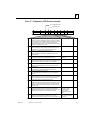
Commands to Display/Control PLC Features
to display the PLC program name: Use the PROG command.
to display the status of Port 1: Use the PORT1 command to show whether
PLC Port 1 (the RS-232 serial port) is in its normal configured operation or
forced local Station Manager operation. The Port 1 LED always shows the
status of the port.
to toggle the Port 1 Override: Use the LOGIN command to enter modify
mode, then use the CHPORT1 command to toggle the operation of Port 1
between its normal configured operation and forced local Station Manager
operation. Using this command has the same effect as pressing the Ethernet
Restart pushbutton for 5 seconds.
Commands to Display/Control Station Manager Operation
3-2
to display the available Station Manager commands: Use the HELP
command.
to place the Station Manager in Modify mode: Use the LOGIN command
and enter the password.
to display the Station Manager login inactivity timeout: Use the LTIME
command.
to change the login inactivity timeout: Use the LOGIN command to enter
modify mode, then use the CHLTIME command to change the secure login
inactivity timeout.
to change the Station Manager Monitor access password: Use the LOGIN
command to enter modify mode, then use the CHPARM command to enter the
new password character string.
to send a command to a remote node: Use the LOGIN command to enter
modify mode, then use the REM command. The Station Manager on the remote
node acts on the command as if it had been entered at its local serial port, but
directs all output from processing the command back over the network to the
station where the REM command originated.
to exit Modify mode: Use the LOGOUT command.
VersaMax™ PLC Station Manager User's Manual – March 2001
GFK-1876
3
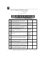
Commands to Display/Control the Ethernet Interface Setup
to display basic ID and setup information for the Ethernet interface: Use
the NODE command.
to display the Ethernet configuration: Use the SOSW command to show the
current setting of the Ethernet configuration data (soft switches) and to indicate
their source. This command also displays the current port usage of Port 1.
to change the backup Ethernet configuration: If a PLC configuration has not
been stored into the CPU, use the LOGIN command to enter modify mode, then
use the CHSOSW command to change the backup configuration parameters of
the Ethernet interface.
to display the internal Ethernet time/date: Use the TIME command to show
the current date and time maintained by the Ethernet interface. This command
also indicates whether the Ethernet interface date and time are synchronized to
the PLC CPU or to the Ethernet network (network time server).
to change the internal Ethernet time/date temporarily: Use the LOGIN
command to enter modify mode, then use the CHTIME command. The Ethernet
interface internal clock will be set to “not synchronized”. This command does
not change the time kept in the PLC CPU, and it remains in effect only until the
Ethernet interface is power-cycled or restarted.
to display some/all Advanced User Parameters: Use the PARM command.
to change the backup Advanced User Parameters: Use the LOGIN
command to enter modify mode, then use the CHPARM command to modify
the value of a selected parameter. When all parameters have been modified,
restart the Ethernet interface to use the modified parameters.
Commands to Display/Control Ethernet Interface Operation
GFK-1876
to force the Ethernet interface to be online or offline: Use the LOGIN
command to enter modify mode, then use the NET command. This command
takes an Ethernet interface on or off the network without physically
disconnecting it or restarting the hardware.
to restart the Ethernet interface firmware: Use the LOGIN command to
enter modify mode, then use the RESTART command to restart the Ethernet
interface without reloading the firmware. Using this command has the same
effect as pressing the Restart pushbutton for less than 5 seconds. Any data
transfer between the PLC and the network at the time the RESTART command
is entered is permanently lost.
Chapter 3 Station Manager Command Summary
3-3
3
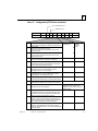
Commands to Display/Control Network Activities
to ping (send an echo request to) a network device: Use the LOGIN
command to enter modify mode, then use the PING command to generate a
sequence of ICMP Echo requests to a specific network device. Login is
maintained until the PING has ended.
to display the latest PING results: Use the REPP command. The results
indicate a currently-running PING sequence or the results from the most recent
PING to run.
to stop a PING in progress: Use the LOGIN command to enter modify mode,
then use the STOPP command to immediately stop an active PING and display
the results. Use this command to terminate a long–running PING sequence.
to delete an SRTP connection: (for diagnostics and maintenance only) Use the
LOGIN command to enter modify mode, then use the KILLSS command. This
command deletes only connections that are in the ESTABLISHED state.
Commands to Display Ethernet Status Information
3-4
to display status information about Ethernet tasks: Use the STAT command.
to display the Exception Log: Use the LOG command. See chapter 6,
“Exception Events” for instructions and information.
to reset the STAT LED without clearing the Exception log: Use the LOGIN
command to enter modify mode, then use the OK command.
to clear/reset Exception Log and reset the STAT LED: Use the LOGIN
command to enter modify mode, then use the CLEAR LOG command. To reset
the STAT LED without clearing the exception log, use the OK command.
to display various operating counters: Use the TALLY command to show the
current value of the tallies for specified tasks. Some tallies indicate load and
performance information about the station. Others can show if there are
problems within the station or within the network. See chapter 5 for
instructions and information.
to clear the re-settable tallies: Use the LOGIN command to enter modify
mode, then use the CLEAR TALLY command. See chapter 5, “Tallies of
Ethernet Tasks” for instructions and information.
to display activity for debug: Use the LOGIN command to enter modify
mode, then use the TRACE command to display a diagnostic trace of certain
specified Ethernet tasks. Login is maintained until the trace has ended. This
command should only be used in debugging problems. It should NEVER be
left enabled in operational nodes.
to display individual EGD exchange information: Use the XCHANGE
command to show detailed information about a specified Ethernet Global Data
exchange, as identified by a producer ID and exchange ID.
VersaMax™ PLC Station Manager User's Manual – March 2001
GFK-1876
Chapter
Station Manager Command Reference
4
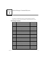
This chapter is an alphabetical reference to the Station Manager commands. It
describes how to execute each Station Manager command and interpret its results.
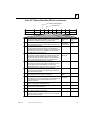
Station Manager Commands
Command
chltime
chparm
chport1
chsosw
chtime
clear
help
?
killss
log
login
logout
ltime
net
node
ok
parm
ping
port1
prog
rem
repp
restart
sosw
stat
stopp
tally
time
trace
xchange
GFK-1876
Function Performed
Change login inactivity timeout
Change backup Advanced User Parameters
Toggle Port 1 override
Change backup Ethernet configuration
Change internal Ethernet clock
Clear selected status information
Display Station Manager command set
Display Station Manager command set
Delete an SRTP connection
Display current exception log
Enter Modify access level
Exit Modify access level
Display login inactivity timeout
Force network offline/online
Display basic identification
Reset STAT LED (log isn’t cleared)
Display the Advanced User Parameters
Send ICMP Echo requests
Display Port 1 status
Display PLC logic program name
Send command to remote node
Display latest ping results
Restart Ethernet firmware
Display Ethernet configuration
Display various operating status
Stop ping in progress
Display various operating counters
Display internal Ethernet clock
Display activity for debug
Display individual EGD exchange information
Available in this Mode
Modify
Modify
Modify
Modify
Modify
Modify
Monitor
Monitor
Modify
Monitor
Monitor
Modify
Monitor
Modify
Monitor
Modify
Monitor
Modify
Monitor
Monitor
Modify
Modify
Modify
Monitor
Monitor
Modify
Monitor
Monitor
Modify
Monitor
4-1
4
CHLTIME
Available in Modify mode.
Use the CHLTIME command to change the login inactivity timeout value. The
change will remain in effect until the time expires, until the timeout period is
explicitly changed, or until the next LOGOUT command is entered. If the number
of minutes specified is zero, the login inactivity timeout is not enforced.
The login inactivity timeout clock is suspended during execution of a TRACE or
PING command.
CHLTIME Command Format
CHLTIME
<minutes>
< minutes >
is the login inactivity timeout value in minutes.
The range is 0 to 32767.
CHLTIME Command Example
= chltime 5
Login timeout = 5 min
4-2
VersaMax® PLC Station Manager User's Manual – April 2001
GFK-1876
4
CHPARM
Available in Modify mode.
Before a PLC configuration has been stored into the PLC, you can use the
CHPARM command to change the value of a specific Advanced User Parameter.
However, it is not recommended that you change any Advanced Parameter other
than “stpasswd”. Be careful when setting any Advanced Parameter. Poor choice of
settings may result in degraded Ethernet interface operation. If you change these
parameters, record the original values for future reference.
Changes do not take effect until the Ethernet interface is restarted or power is
cycled. Advanced User Parameters are saved in battery-backed memory. If battery
backup is lost, then any loss of power will cause the backup of these parameters to
be lost. Changes made by the CHPARM command are retained over restart and
power cycles, until changed again by the CHPARM command.
After the PLC configuration has been stored into the PLC, the CHPARM command
is prohibited and any previous changes made with it are no longer effective.
Changes to the default Advanced User Parameter values should be made via an
optional Advanced User Parameter file. See the VersaMax PLC User’s Manual
(GFK-1503) for details.
CHPARM Command Format
CHPARM < parm name >
{ < value > |
def }
or
CHPARM all def
<parm name>
specifies the name of an advanced user parameter (listed in
the PARM command description later in this chapter).
<value>
specifies the new value for the specified advanced user
parameter.
“def”
GFK-1876
may be entered instead of an actual value to set the specified
parameter to its factory default value.
Chapter 4 Station Manager Command Reference
4-3
4
CHPARM Command Example
= chparm ifrag_tmr 4
Parameter changes take effect at the next power up or restart Changes are updated
to the PLC Configuration at the next power cycle or PLC configuration CLEAR. To
avoid losing parameter changes, be sure to power cycle or CLEAR before
LOADing PLC configuration to the programmer).
Using CHPARM to Change the Station Manager Password
The default Station Manager password is “system”. The normal way to change the
password is via the “stpasswd” parameter in the Advanced User Parameter file.
When a PLC configuration has not been stored into the PLC, the Station Manager
password maybe changed by the CHPARM command; the parameter name is
“stpasswd”. In order to use the CHPARM command, the current password is
required to access the “Modify level” of the Station Manager. Note that the Station
Manager password parameter value will be converted to lowercase unless you
enclose the value within double quotes.
What to Do if You Have Forgotten Your Password
If the Station Manager password has been set to a non-default value and you have
forgotten the current password, you will be unable to enter Modify mode or use the
modify level CHPARM command. In this case, you must either examine the
“stpasswd” parameter in the Advanced User Parameter file for this PLC to
determine the actual password, or store another Advanced User Parameter file with
a known password to the PLC.
4-4
VersaMax® PLC Station Manager User's Manual – April 2001
GFK-1876
4
CHPORT1
Available in Modify mode.
Use the CHPORT1 command to set the operation of Port 1 (the RS-232 serial port)
to either its normal configured operation or forced local Station Manager operation.
Using this command has the same effect as pressing the Ethernet Restart pushbutton
for 5 seconds. This command has no effect if Port 1 was configured from the
programmer to be restricted to Local Station Manager operation.
CHPORT1 Command Format
CHPORT1 {
sta
|
cfg
}
sta
forces Port 1 to local Station Manager operation.
cfg
returns the port to its normal configured operation.
CHPORT1 Command Example
= chport1 sta
Port 1 overridden for Station Manager operation
Checking the Status of Port 1
The Port 1 LED always shows the status of the port, even after toggling the port
operation. In addition, the PORT1 command can be used to display the status of
Port 1. See PORT1 later in this chapter.
GFK-1876
Chapter 4 Station Manager Command Reference
4-5
4
CHSOSW
Available in Modify mode.
Before a configuration has been received from the CPU, you can use the CHSOSW
command to change the backup configuration parameters of the Ethernet interface.
Changes made by the CHSOSW command do not take effect until the Ethernet
interface is restarted or power cycled. The changes remain in effect until a new
configuration is supplied by the CPU.
After the Ethernet interface receives a configuration from the PLC CPU, the
CHSOSW command is prohibited and any previous changes made with it are no
longer effective.
CHSOSW Command Format
CHSOSW
{ < sosw
data >
|
def }
def
sets all values to their defaults
ip_address
dotted–decimal IP address
subnet_mask
dotted–decimal subnet mask
gateway
dotted–decimal default gateway address
p1_data_rate
p1_data_rate (4800, 9600, 19200, 38400, 57600, 115200)
p1_parity
p1_parity (NONE, ODD, EVEN)
p1_flow_control
p1_flow_control (NONE, HARDWARE)
ntp_host1_addr
IP address of first NTP time server
ntp_host2_addr
IP address of second NTP time server
ntp_host3_addr
IP address of third NTP time server
CHSOSW Command Example
= chsosw
ip_address
10.0.0.2
Parameter changes take effect at the next power up or restart Changes are updated
to the PLC Configuration at the next power cycle or PLC configuration CLEAR.
To avoid losing configuration changes, be sure to power cycle or CLEAR before
LOADing PLC configuration to the programmer.
4-6
VersaMax® PLC Station Manager User's Manual – April 2001
GFK-1876
4
CHTIME
Available in Modify mode.
Use the CHTIME command to set both the time and date for the Ethernet interface.
When modified with the CHTIME command, the Ethernet interface internal clock is
set to “not synchronized”. This command is rejected if the Ethernet interface is
synchronized to external NTP time servers.
A time value is required date value is optional. Valid dates are JAN 01, 1998 – DEC
31, 2097. If an invalid date or time is entered, the internal clock is not changed.
Changes remain in effect until the Ethernet interface is power-cycled or restarted.
This command applies only to the Ethernet interface; it does not change the time
kept in the PLC CPU.
CHTIME Command Format
CHTIME
[
< MMM
DD, YYYY > ]
< HH [ : MM [ : SS ] ] >
<MMM>
is the month (JAN . . . DEC)
<DD>
is the day of the month (1-31)
<YYYY>
is the year (1998 . . .)
<HH>
is an hour in the range 0–23
<MM>
is an optional minute in the range 0–59 which defaults to 0
<SS>
is an optional second in the range 0–59 which defaults to 0
Leading zeros do not need to be entered.
CHTIME Command Example
= chtime feb 21, 2001
23:00:10
Feb 21, 2001
23:00:10.2
Date/time not synchronized
GFK-1876
Chapter 4 Station Manager Command Reference
4-7
4
CLEAR
Available in Modify mode.
Use the CLEAR command to set Ethernet interface data to initial values, usually
zeros. When clearing the exception log, the STAT LED is reset to green, indicating
the exception log is empty.
CLEAR Command Format
CLEAR
{ log
|
tally }
log
discards all log entries and sets the log to an
empty state. Also resets the STAT LED on the
Ethernet interface to green.
tally
sets all resettable tallies to zero.
CLEAR Command Example
= clear tally
Tallies cleared
4-8
VersaMax® PLC Station Manager User's Manual – April 2001
GFK-1876
4
HELP
Available in Monitor or Modify mode.
Use the HELP command (or enter the single character command “?”) to display a
list of Station Manager commands.
HELP Command Format
HELP
or
?
HELP Command Example 1: Not Logged In (Monitor Level)
If you are not logged in, you will see only the Monitor-level commands.
> help
<<< Monitor Commands >>>
?
help
log
login
ltime
node
parm
port1
prog
sosw
stat
tally
time
xchange
HELP Command Example 2: Logged In
If you are logged in to use Modify commands, you will also see all Monitor–level
commands in the command list.
= help
<<< Monitor Commands >>>
?
help
log
login
ltime
node
parm
port1
prog
sosw
stat
tally
time
xchange
<<< Modify Commands >>>
GFK-1876
chltime
chparm
chport1
chsosw
chtime
clear
killss
logout
net
ok
ping
rem
repp
restart
stopp
trace
Chapter 4 Station Manager Command Reference
4-9
4
KILLSS
Available in Modify mode.
This command should be used only for diagnostics and maintenance because it
disrupts the communication on an STRP connection.
Use the KILLSS command to delete an established SRTP connection. This
command does not delete connections that are not in the ESTABLISHED state.
A connection is identified by an endpoint number, as listed in the leftmost column
of the STAT v command output. See the description of STAT later in this chapter for
information.
KILLSS Command Format
KILLSS {all | < SRTP Server Endpoint > [ < SRTP Server Endpoint > [...]]}
< SRTP Server
Endpoint >
endpoint number of connection to be terminated.
all
terminates all established SRTP Server endpoints.
KILLSS Command Example
= killss 2 3 6
SRTP Server endpoint 2 shut down initiated
SRTP Server endpoint 3 shut down initiated
SRTP Server endpoint 6 shut down initiated
4-10
VersaMax® PLC Station Manager User's Manual – April 2001
GFK-1876
4
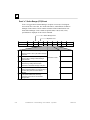
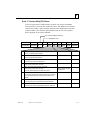
LOG
Available in Monitor or Modify mode.
Use the LOG command to display the exception log without any internal status code
data. Use the LOG Z command to display the exception log including the additional
status code data. The LOG Z command requires a 132-column display format. See
the example below for the data displayed by the two forms of the LOG command.
The exception log is a circular list; a new event overwrites the oldest event in the
list. An arrow points to the most recent event. Events stay in the log until they are
cleared with the CLEAR LOG command or until they are overwritten. The
exception log is maintained in battery-backed memory; the exception log contents
are retained over normal power outage. Refer to chapter 6, “Exception Events” for
detailed information about Exception Events.
LOG Command Format
LOG
[ z ]
z
display additional status and addressing data
LOG Command Example
> log
<<< Exception Log >>>
IC200CPUE05 Embedded Ethernet version 2.10 (34A1)
Log displayed 04-AUG-2000 11:25:28.3
Log initialized using valid RAM information
Log last cleared 31-JUL-2000 09:33:46.9
Date
Time
Event Count Entry 2 through Entry 6
03-AUG-2000 09:33:47.0
1H
1H
0000H 0001H 0000H 0000H 0000H
03-AUG-2000 09:33:47.0
0H
1H
MII/PHY Fail
03-AUG-2000 14:01:22.2
20H
1H
0001H 0000H 0000H 0001H 0117H
->03-AUG-2000 09:33:47.2
2aH
1H
0004H 0000H 0000H 0004H 0192H
LOG Z Command Example
> log z
<<< Exception Log >>>
IC200CPUE05 Embedded Ethernet version 2.10 (34A1)
Log displayed 04-AUG-2000 11:25:28.3
Log initialized using valid RAM information
Log last cleared 31-JUL-2000 09:33:46.9
Date
Time
Event Count Entry 2 through Entry 6
SCode
03-AUG-2000 09:33:47.0
1H
1H
0000H 0001H 0000H 0000H 0000H
03-AUG-2000 09:33:47.0
0H
1H
MII/PHY Fail
80010605H
03-AUG-2000 14:01:22.2
20H
1H
0001H 0000H 0000H 0001H 0117H
->03-AUG-2000 09:33:47.2
2aH
1H
0004H 0000H 0000H 0004H 0192H
GFK-1876
Chapter 4 Station Manager Command Reference
Remote IP Addr:Port
or Producer ID:Exchg
Local IP Addr:Port
4-11
4
Each exception event contains:
Date
the system date of the last occurrence of the logged
event.
Time
the system time of the last occurrence of the logged
event. The timestamp used is the current date and
time of day as known by the Ethernet interface.
Event
the kind of event that occurred. Events are described
in chapter 6.
Count
a repetition count for the event. If identical events
occur regularly, they can flood the log with useless
entries. Instead of recording each repeated event in
detail, the log simply keeps the time of the latest event
and a count of the number of repetitions of the
repeated event. Log entries are retained on restarts
and reloads of the Ethernet interface.
Entry
information about the event, divided into 5 entries,
Entry 2 – Entry 6.
Additionally, some exception events may provide one or more of the following:
4-12
SCode
a 32-bit internal status code providing additional
detail.
Remote IP Addr: Port
the IP address and port of the remote device
associated with the failure.
Local IP Addr: Port
the local IP address and port on the device where the
failure occurred.
Producer ID: Exchg
for Ethernet Global Data events, the complete
identifier of a particular exchange.
VersaMax® PLC Station Manager User's Manual – April 2001
GFK-1876
4
LOGIN
Available in Monitor or Modify mode.
Use the LOGIN command to change the present privilege level of the Station
Manager in order to access the Modify commands.
LOGIN Command Format
LOGIN
The LOGIN command is followed by the password prompt:
Password:
Enter your password (it is not echoed). All keys pressed after the prompt except the
Enter key are considered part of the password. The delete and backspace characters
do not have their usual meanings; they are interpreted as password characters. The
password may not include tabs or spaces.
Passwords are limited to 8 characters and all characters after the eighth are ignored.
When issued locally via the Local Station Manager terminal, the password does
NOT need to be enclosed in double quotes to be case-sensitive.
If the password matches the current password for the Modify level, a confirmation
message appears and you can access the Modify commands. If the password does
not match, an error message appears and the security level does not change.
Example (Local)
> login
Password: system
Logged in
=
The Default Password
The factory default password is:
system
(lower case).
The password is normally changed using the Advanced User Parameters. It can also
be changed by using the CHPARM STPASSWD command.
Log into a Remote System
The LOGIN command may be used with the REM (remote) command to log into a
remote system. Refer to the REM command description in this chapter.
GFK-1876
Chapter 4 Station Manager Command Reference
4-13
4
LOGOUT
Available in Modify mode.
Use the LOGOUT command to terminate the secure login. Modify commands
entered after the logout receive an error message. Logging out causes the login
inactivity timeout value to return to 10 minutes for the next login.
LOGOUT Command Format
LOGOUT
LOGOUT Command Example
= logout
Logged out
>
4-14
VersaMax® PLC Station Manager User's Manual – April 2001
GFK-1876
4
LTIME
Available in Monitor or Modify mode.
Use the LTIME command to display the current login inactivity timeout value.
The login inactivity timeout value can be changed using the CHLTIME command.
LTIME Command Format
LTIME
LTIME Command Example
> ltime
Login timeout = 10 min
NET
Available in Modify mode.
Use the NET command to cause the Ethernet interface to either ignore incoming and
outgoing Ethernet frames (when NET OFF is specified) or to accept incoming and
outgoing Ethernet frames (when NET ON is specified). This command can be used
to remove an Ethernet interface from the network without the need to physically
disconnect it or restart the hardware.
NET Command Format
NET
{ ON
|
OFF }
off
take the Ethernet interface off the network
on
attempt to put the Ethernet Interface on the
network
NET Command Example
= net off
Interface off network
GFK-1876
Chapter 4 Station Manager Command Reference
4-15
4
NODE
Available in Monitor or Modify mode.
Use the NODE command to display the Ethernet interface sign–on message.
NODE Command Format
NODE
NODE Command Example 1
> node
IC200CPUE05 Embedded Ethernet
Copyright (c) 2001. All rights reserved.
Version 2.10 (11A1) TCP/IP
Version 2.00 (38A1) Loader
IP Address = 10.0.0.2
Subnet Mask = 255.255.0.0
MAC Address = <<080019010203>>
Gateway = 0.0.0.0
NTP Time Servers (1,2,3) = 0.0.0.0, 0.0.0.0, 0.0.0.0
Station Manager at Port 1:
Data Rate = 9600, Parity = NONE, Flow Control = NONE
Port 1 configured for Station Manager; not overridden
Source of Soft Switches: CPU
Advanced User Parameters are modified; use “parm” command to display
August 28, 2001, 16:00:05
Date/time initialized from PLC CPU
OK
Available in Modify mode.
The STAT LED is set to amber when an entry is placed into the exception log. You
can use the OK command to turn the STAT LED green again. This command has
no effect on the contents of the exception log.
OK Command Format
OK
OK Command Example
= ok
STAT LED modified
4-16
VersaMax® PLC Station Manager User's Manual – April 2001
GFK-1876
4
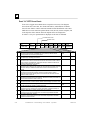
PARM
Available in Monitor or Modify mode.
Use the PARM command to display the current value of the Advanced User
Parameters (listed on the following pages) for specified task(s). All Advanced User
Parameters for the specified tasks are displayed. Pending changes may cause data to
scroll off some screens. Soft switch configuration parameters for the specified tasks
are not displayed; use the SOSW command to display those.
PARM Command Format
parm { < tasks >
|
all
}
all
displays all advanced user parameters.
<task>
specifies a task identifier.
c
PLC Driver
f
i
b
l
w
ARP
IP
System Memory
Network Interface
TCP
n
NTP
g
Ethernet Global Data
PARM Command Example
= parm i
<<< IP Parameters >>>
Default Value
ittl
=
64 (40H)*
ifrag_tmr =
3 (0003H)*
User-Set Value
* An asterisk identifies the currently active value.
Pending local changes (must powerup or restart to activate):
ifrag_tmr = 4 (0004H)
GFK-1876
Chapter 4 Station Manager Command Reference
4-17
4
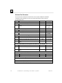
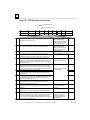
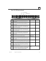
Advanced User Parameters
The Advanced User Parameters listed below are used by the PARM and CHPARM
commands. These parameters are also used for the data portion of the Advanced
User Parameters file.
Parameter
Description
System Memory Parameters (task b)
staudp
Remote command UDP port
stpasswd
Station Manager password (only visible from MODIFY
prompt)
PLC Driver Parameters (task c)
crsp_tout
Transfer/response timeout in seconds
ARP Parameters (task f)
fflush
Interval in seconds at which to flush the ARP cache
Default Value
Range
18245 (4745H)
“system”
0 – 65535 (ffffH)
0-8 characters,
case sensitive, no
spaces
16 (0010H)
10 – 3600 (0e10H)
600 (0258H)
0 – 604800
(93A80H)
Ethernet Global Data Parameters (task g)
gctl_port
UDP port for EGD control messages
7937 (1f01H)
0 – 65535 (ffffH)
gdata_port UDP port for point-to-point (unicast) EGD messages
18246 (4746H) 0 – 65535 (ffffH)
gbcast_ttl IP time-to-live for global broadcast messages (hop count)
1 (1H)
0 – 255 (00ffH)
gucast_ttl IP time-to-live for point-to-point (unicast) messages (hop
16 (10H)
0 – 255 (00ffH)
count)
EGD provides a UDP port parameter and host group IP address parameter for each of 32 possible host groups
(0-31). The parameter formats for each host group are shown below. XX specifies host group 0-31.
gXX_udp
UDP port for host group XX
18246 (4746H) 0 – 65535 (ffffH)
gXX_addr IP time-to-live for host group XX (must be Class D address)
224.0.7.XX
224.0.0.2 –
239.255.255.255
IP time-to-live for host group (multicast) messages (hop
gXX_ttl
1 (1H)
0 – 255 (00ffH)
count)
SRTP Channels Parameters (task ‘h’) (none)
IP Parameters (task i)
ittl
IP header default time–to–live (hop count)
ifrag_tmr
IP fragment timeout interval in seconds
ICMP/IGMP Parameters (task ‘j’)
(none)
64 (0040H)
3 (00003H)
0 – 255 (00ffH)
0 – 65535 (ffffH)
Network Interface Parameters (task ‘l’) (none)
UDP Parameters (task ‘u’) (none)
SRTP Server Parameters (task ‘v’)
(none)
4-18
VersaMax® PLC Station Manager User's Manual – April 2001
GFK-1876
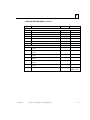
4
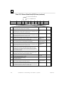
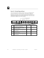
Advanced User Parameters (continued)
Parameter
Description
TCP Parameters (task ‘w’)
wnodelay
TCP nodelay option (0= inactive; 1 = active)
wkal_idle
TCP keepalive timer value (in seconds)
wkal_cnt
TCP keepalive probe count
0, 1
0 − 65535 (ffffH)
0 − 65535 (ffffH)
0 (000H)
240 (00f0H)
2 (0002H)
wkal_intvl
wmsl
0 − 65535 (ffffH)
0 − 65535 (ffffH)
60 (003cH)
30 (001eH)
0 − 32767 (7fffH)
0 − 32767 (7fffH)
4096 (1000H)
4096 (1000H)
6 (0006H)
4 – 14 (000eH)
10 (000aH)
4 – 14 (000eH)
6 (0006H)
4 – 14 (000eH)
10 (000aH)
4 – 14 (000eH)
6 (0006H)
4 – 14 (000eH)
10 (000aH)
4 – 14 (000eH)
300 (012cH)
150-65535
0096H – ffffH)
TCP keepalive probe interval (in seconds)
TCP maximum segment lifetime (in seconds)
wsnd_buf
TCP send buffer size (in bytes)
wrcv_buf
TCP receive buffer size (in bytes)
NTP Parameters (task n)
nmin_poll1
NTP min. poll interval for NTP server 1 in log(2) of
seconds
nmax_poll1 NTP max. poll interval for NTP server 1 in log(2) of
seconds
nmin_poll2
NTP min. poll interval for NTP server 2 in log(2) of
seconds
nmax_poll2 NTP max. poll interval for NTP server 2 in log(2) of
seconds
nmin_poll3
NTP min. poll interval for NTP server 3 in log(2) of
seconds
nmax_poll3 NTP max. poll interval for NTP server 3 in log(2) of
seconds
nsync_tout
NTP synchronization timeout period in seconds
GFK-1876
Chapter 4 Station Manager Command Reference
Default Value
Range
4-19
4
PING
Available in Modify mode.
Use the PING command to generate ICMP Echo requests to validate network
connectivity.
The PING command is refused if the Ethernet interface on which you are issuing
the PING command to has not been configured with a valid IP address.
Login is maintained (automatic inactivity logout is inhibited) until the PING
sequence has ended.
The results of the last PING command are maintained until the Modify-level login
is exited. Use the REPP command to display the results of the most recent PING
command. Only one PING command can be active at a time.
PING Command Format
PING
node
<node> [ <cnt> [ <sch> [ <len> ] ] ]
the IP address of the remote node to be “pinged” (i.e., to be
sent ICMP Echo Request messages).
Enter in standard IP dotted–decimal form.
cnt
the number of times the ping is to be repeated.
Default is 1. Range is 1 through ffffffffH.
sch
the maximum amount of time to wait for a reply to each ping.
The timeout interval is expressed in 10–millisecond units.
Default is 100 (1 second). Range is 0 through 7fffH.
A value of 0 results in the value of 100 (1 second) delay
used.
len
the number of data bytes in the Echo Request message. The
actual data pattern is not changeable by the user. Default
length is 64 bytes. Range is 8 through 32747 but is limited
by system buffer memory.
PING Command Example
= ping 10.0.0.2 10
Ping initiated
<<< Ping Results >>>
Command: ping 10.0.0.2 10 100 64
Sent = 10, Received = 10, No Timely Response = 0
Late/Stray Responses = 0
Round–trip (ms) min/avg/max 0/1/10
See also the REPP command for detailed explanation of PING results.
4-20
VersaMax® PLC Station Manager User's Manual – April 2001
GFK-1876
4
PORT1
Available in Monitor or Modify mode.
Use the PORT1 command to show whether Port 1 (the RS-232 serial port) is in its
normal configured operation or forced local Station Manager operation. The Port 1
LED always shows the status of the port.
You can use the CHPORT1 command in modify mode to toggle the operation of
Port 1 between its normal configured operation and forced local Station Manager
operation. See CHPORT1 earlier in this chapter.
PORT1 Command Format
PORT1
PORT1 Command Example
> port1
Port 1 configured for PLC communication; not overridden
PROG
Available in Monitor mode.
Use the PROG command to show the name of the current PLC CPU application
program.
PROG Command Format
PROG
PROG Command Example
> prog
CPU Program Name is “CONVEY4”
GFK-1876
Chapter 4 Station Manager Command Reference
4-21
4
REM
Available in Modify mode.
Use the REM command to send a Station Manager command to a remote Ethernet
interface for processing. The Station Manager on the remote node acts on the
command as if it had been entered at its local serial port, but directs all output from
processing the command back over the network to the station where the REM
command originated.
The results are displayed at the local station with the notation “REM” along with the
prompt from the remote station. An Ethernet interface cannot use the REM
command to send a REM command to another Ethernet interface. An Ethernet
interface cannot use the REM command to send any command to itself.
REM Command Format
REM
<node> <cmd> [<cmd parms>]
node
the IP address of the remote Ethernet interface
cmd
is any Station Manager command except REM
cmd parms
is a list of any parameters required by <cmd>
Do NOT send the REM command itself to an Ethernet interface (i.e.,
= rem <node> rem <node> <command> )
REM Command Example
= rem 10.0.0.2 node
REM> IC693 PLC Factory LAN Interface
REM> Copyright (c) 1998. All rights reserved.
REM> Version 1.00 (28A1) TCP/IP
REM> Version 1.00 (28A1) Software Loader
REM> IP Address = 10.0.0.2
REM> MAC Address = <<080019010177>>
Log into a Remote System
When using the REM command to send a LOGIN command to log into a remote
system, you must enter the password value along with the LOGIN command.
REM <node> LOGIN <password>
If the password contains any uppercase letters, place it in double quotes; passwords
are case sensitive.
Security is enforced on the remote system just as if the command had been entered
locally. The remote user and any local user of a given node all see the same
security level.
4-22
VersaMax® PLC Station Manager User's Manual – April 2001
GFK-1876
4
REPP
Available in Modify mode.
Use the REPP command to report the results of the PING command. The results
may be for a currently-running PING or the most recent PING command.
REPP Command Format
REPP
REPP Command Example
= repp
<<< Ping Results >>>
Command: ping 10.0.0.2 10 100 64
Sent = 1, Received = 1, No Timely Response = 0
Late/Stray Responses = 0
Round–trip (ms) min/avg/max 0/1/10
Note: The ping is still active
In the response:
GFK-1876
Command
identifies the actual PING command parameters used
(including default values for any optional parameters not
specified on the command line) to generate the results
Sent
shows the number of Echo Request messages sent.
Received
shows the number of Echo Reply messages received within
the expected response schedule of a corresponding Echo
Request. The response schedule begins when an Echo
Request is sent and ends when the schedule time specified
in the <sch> parameter of the PING command elapses.
No Timely
Response
shows the number of times that no Echo Response message
arrived within the response schedule of the corresponding
Echo Request; that is, when the response schedule time
elapses before the corresponding Echo Response arrives.
Late/Stray
Responses
indicates the number of times an Echo Response arrived
outside of the response schedule of its corresponding Echo
Request or when a stray Echo Response, not corresponding
to any recent Echo Request, arrives.
Round–trip
indicates the minimum, average, and maximum delay (in
units of milliseconds) measured between sending an Echo
Request and receiving the corresponding Echo Response.
These times use 1 millisecond increments.
Chapter 4 Station Manager Command Reference
4-23
4
RESTART
Available in Modify mode.
Use the RESTART command to restart the Ethernet interface without reloading the
software. Using this command has the same effect as pressing the Restart
pushbutton for less than 5 seconds. Any data transfer between the PLC and the
network at the time the RESTART command is entered is permanently lost.
RESTART Command Format
RESTART
RESTART Command Example
= restart
Restarting Module
4-24
VersaMax® PLC Station Manager User's Manual – April 2001
GFK-1876
4
SOSW
Available in Monitor or Modify mode.
Use the SOSW command to show the current setting of the Ethernet configuration
data (soft switches) and to indicate their source. This command also displays the
current port usage of Port 1.
SOSW Command Format
SOSW
SOSW Command Example
> sosw
<<< Soft Switch
IP Address
Subnet Mask
Gateway
NTP Time Server
NTP Time Server
NTP Time Server
Data >>>
= 10.0.0.2
= 255.255.0.0
= 0.0.0.0
1 = 0.0.0.0
2 = 0.0.0.0
3 = 0.0.0.0
(TCP/IP values from Soft Switches)
Station Manager at Port 1:
Data Rate
= 9600
Parity
= NONE
Flow Control = NONE
Port 1 configured for PLC communication; not overridden
Source of Soft Switches: Autoconfiguration
Advanced User Parameters are modified; use “parm” command to display
Pending local changes (must powerup or restart to activate):
p1_data_rate = 38400
ntp_host1_addr = 3.16.17.214
ntp_host2_addr = 3.20.143.5
ntp_host3_addr = 3.17.19.40
Sources for the soft switches are:
GFK-1876
PLC Configuration
settings received in the configuration from the PLC
CPU.
Autoconfiguration
settings derived from autoconfiguration
Backup
settings retrieved from the Ethernet interface’s
internal backup. This is expected when configuration
has not been received from the PLC CPU.
Factory Default
settings are factory defaults. This is expected when
no current configuration or previously backed up
configuration exists.
Chapter 4 Station Manager Command Reference
4-25
4
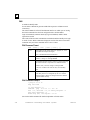
STAT
Available in Monitor or Modify mode.
Use the STAT command to show the current status of the specified task(s).
STAT Command Format
STAT <task(s)>
<task>
may be one or more of the following task identifiers.
l
Network Interface
u
UDP
i
IP
b
System Memory
c
PLC Driver
g
Ethernet Global Data
j
ICMP, IGMP
w
TCP
f
ARP
n
NTP
v
SRTP Server
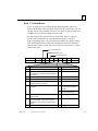
STAT Command Example
> stat v
<<< SRTP Server Status >>>
4-26
Endpoint
Task
State
Num Requests
Client Address
--------
----
-----------
------------
--------------
0
32
ESTABLISHED
10906
10.0.0.4
1
33
ESTABLISHED
10916
10.0.0.4
2
34
ESTABLISHED
10931
10.0.0.4
3
35
ESTABLISHED
10911
10.0.0.4
VersaMax® PLC Station Manager User's Manual – April 2001
GFK-1876
4
STOPP
Available in Modify mode.
Use the STOPP command to immediately stop an active PING and print the results.
This command is used to terminate a long–running PING sequence.
STOPP Command Format
STOPP
STOPP Command Example
= stopp
<<< Ping Results >>>
Command: ping 10.0.0.2 10 100 64
Sent = 8, Received = 8, No Timely Response = 0
Late/Stray Responses = 0
Round–trip (ms) min/avg/max 0/1/10
Note: The ping was aborted.
GFK-1876
Chapter 4 Station Manager Command Reference
4-27
4
TALLY
Available in Monitor or Modify mode.
Use the TALLY command to show the current value of the tallies for the specified
tasks. Some tallies indicate load and performance information about the station.
Others can show if there are problems within the station or within the network.
All tallies are displayed as 32-bit hexadecimal numbers.
TALLY Command Format
TALLY <task(s)>
<task>
may be one or more of the following task identifiers.
l
Network Interface
u
UDP
i
n
IP
NTP
v
SRTP Server
j
w
ICMP, IGMP
TCP
f
ARP
c
PLC Driver
g
Ethernet Global Data
TALLY Command Example
> tally c
<<< PLC Driver Tallies >>>
03-JAN-1998
21:22:36.168
UsrReq
=00000003H
UsrRsp
=00000003H
UsrMsg
=00000000H
UnsolMsg=00000002H
PlcReq
=00000002H
PlcRsp
=00000002H
Cmrq
=00000000H
CmrqDscd=00000000H
PlcSweep=00000000H
PktToPlc=00000005H
PktFmPlc=00000007H
PktUnreg=00000000H
BsyRetry=00000000H
BpdAbort=00000000H
PlcTmout=00000000H
UsrTmout=00000000H
<<< Shared Memory Interface Tallies >>>
SendObtn=00000005H
MBSend
MBAvail =00000008H
Busy
03-JAN-1998
21:22:36.177
MBResend=00000000H
SndAbort=00000000H
RecvObtn=00000008H
MBRecv
=00000008H
RcvAbort=00000000H
Idle
=00000000H
Hrtbeats=000002e4H
ClrDbCfg=00000000H
InptScan=00000000H
FactCmd =00000000H
FactRsp =00000000H
EgdProd =00000000H
UnknCmd =00000000H
HpAlloc =00000000H
HpFree
DblFree =00000000H
=00000000H
=00000005H
=00000000H
Refer to Chapter 5, “Tallies of Ethernet Tasks”, for a list of the tallies and their
meanings.
4-28
VersaMax® PLC Station Manager User's Manual – April 2001
GFK-1876
4
TIME
Available in Monitor or Modify mode.
Use the TIME command to show the current internal clock (date and time)
maintained within the Ethernet interface. This command also indicates whether the
Ethernet interface date and time are synchronized to the PLC CPU or to the Ethernet
network. If the date/time are synchronized to a network time server, the recognized
time server is listed.
The Ethernet interface date and time are used in Ethernet Global Data and in the
exception log displayed by the LOG command:
Ethernet Global Data: If the Ethernet interface has been configured to use
Network Time Synchronization, the time–stamp within each produced Ethernet
Global Data exchange is based on the internal clock of the Ethernet interface
that produced the exchange. This may be different from that of the PLC CPU.
For Ethernet Global Data exchanges that are produced by an Ethernet interface
not configured to use Network Time Synchronization, the timestamp in EGD
exchange data is based on the internal clock of the PLC CPU.
Exception Log: The timestamp information in the Exception Log is based on
the internal clock of the Ethernet interface.
PLC Fault Table: The timestamp in the PLC Fault Table is based on the
internal clock of the PLC CPU.
At each powerup or Ethernet restart, the Ethernet interface attempts to set its
internal clock to the date and time read from the PLC CPU. If this is not available,
the internal clock is initialized to 00:00:00:0 January 1, 1998 (the same default
date/time used by the PLC CPU). If NTP time synchronization is configured, the
Ethernet interface internal clock may be updated to values obtained from a remote
NTP server on the network. Time values are displayed in 24-hour format.
TIME Command Format
TIME
TIME Command Example
> time
Feb 28,2001
16:00:05.4
Date/time initialized from PLC CPU
The command CHTIME can be used to change the date/time value.
GFK-1876
Chapter 4 Station Manager Command Reference
4-29
4
TRACE
Available in Modify mode.
Use the TRACE command to display a diagnostic trace of certain specified Ethernet
tasks for troubleshooting purposes. Login is maintained (automatic inactivity logout
is inhibited) until the TRACE has ended. Enabling trace output has severe
performance penalties for the communications software. This command should
only be used in debugging problems. TRACE should NEVER be left enabled in
operational nodes. Only one TRACE command can be active at a time. Each new
TRACE command automatically stops any existing traces. The TRACE command
can be used either locally or remotely. The TRACE command issued last, either
locally or remotely, determines where the display takes place. If a trace is initiated
from a remote Station Manager, trace output continues to be sent to that remote
Station Manager until terminated, even if the remote Station Manager is
disconnected or logged into another station. Be sure to stop your traces.
TRACE Command Format
TRACE !
or
TRACE <task>[(<qual>)][< task(s)>][<mins>[<max_len>]]
Up to 8 tasks may be specified; each task may contain an optional qualifier within
parentheses. All tasks/qualifiers are entered as one parameter without spaces.
TRACE Command Example
= trace v(2)v(5)z 15 64
Trace enabled for: v(2)v(5)z
Minutes remaining = 15
max data displayed = 64
!
up to 8 tasks of the following types can be traced. A letter specifies the task type:
g Ethernet Global Data
v SRTP Server
c
PLC Driver
z
Enables Protocol Data Unit (PDU) tracing for selected traces
qual
optional number that restricts tracing to a specified entry within a task. The
qualifier must be enclosed in parentheses and immediately follows the task letter.
The qualifiers for the above tasks are:
g Ethernet Global Data: Exchange index ( 0 ) - ( 31 )
v SRTP Server:
Connection ID ( 0 ) - ( 7 )
c
PLC Driver:
Mailbox task ID ( 0 ) - ( 127 )
Multiple trace qualifiers of the same task can be specified. See example above.
mins
optional timeout period from 0 (no timeout) to 32767 min. Default is 10 min.
max_len
4-30
disables all tracing . It should only be used by itself.
task
optional length that limits the amount of data displayed from each traced Protocol
Data Unit (PDU). PDU tracing must be enabled via the task identifier ‘z’. The
display length may vary from 1 byte to 32767 bytes; if the optional length value
is not specified, the display length defaults to the first 48 bytes of the PDU.
VersaMax® PLC Station Manager User's Manual – April 2001
GFK-1876
4
Trace Outputs for Ethernet Global Data (Task g)
Typical trace outputs for EGD are shown below. The “ndx” value identifies a
particular Ethernet Global Data exchange. You can display information about this
exchange (such as remote IP address and local UDP port) with the STAT g
command.
egd <-- ndx=1
egd --> ndx=1
Optional Protocol Data Unit data is also displayed if PDU trace is enabled.
Trace Outputs for SRTP Server (Task v)
Typical trace outputs for SRTP Server are shown below. The “conn” value
identifies a particular SRTP Server connection. You can display information about
this connection (such as remote IP address and local TCP endpoint) with the STAT v
command.
srtp svr <-- conn=2
srtp svr --> conn=2
Optional Protocol Data Unit data is also displayed if PDU trace is enabled.
Trace Outputs for PLC Driver (Task c)
Typical trace outputs for the PLC backplane driver are shown below. The “task”
value identifies a particular PLC mailbox message address within the LAN
interface. You can display information about this mailbox address task with the
STAT c command.
plc <-- task=13
plc --> task=0
Optional Protocol Data Unit data is also displayed if PDU trace is enabled.
GFK-1876
Chapter 4 Station Manager Command Reference
4-31
4
XCHANGE
Available in Monitor mode.
Use the XCHANGE command to show detailed information about the configuration
of a specified Ethernet Global Data exchange. Every change is uniquely identified
by its producer ID and exchange ID.
XCHANGE Command Format
xchange < producer ID >
< exchange ID >
producer ID
the ID of the device that produced the exchange
exchange ID
the ID of the exchange
In this command, the producer ID and exchange ID identify an Ethernet Global
Data exchange. The producer ID and exchange ID values for all defined exchanges
may be displayed by using the STAT g command.
XCHANGE Command Example
> xchange 1.2.3.4 1
<<< Individual Exchange Information >>>
Exch. Mode:
PRODUCER
Producer ID:
1.2.3.4
Exchange ID
1
Period:
1000 ms
UDP Port:
5500
Xfer Bytes:
2
Exch Type:
STATIC
Dest IP:
10.16.32.145
Transfer Cnt:
43
Refresh Errs:
0
4-32
VersaMax® PLC Station Manager User's Manual – April 2001
GFK-1876
Tallies of Ethernet Tasks
Chapter
5
This chapter explains how to display and clear information about specific Ethernet
tasks. It also describes the types of information you can display, grouped by task;
Contents of this chapter are:
GFK-1876
Tally Groups
Viewing and Clearing Tallies
Tally Definitions
5-1
5
Tally Groups
The Ethernet interface of CPUE05 maintains a set of tallies that count notable
conditions detected by the Ethernet firmware.
Tallies are grouped and identified by task type:
5-2
PLC Driver Tallies (task ‘c’)
SMI Driver Tallies (also part of task ‘c’)
SRTP Server Tallies (task ‘v’)
Ethernet Global Data Tallies (task ‘g’)
Network Interface Tallies (task ‘l’)
ARP Tallies (task ‘f’)
IP Tallies (task ‘i’)
ICMP/IGMP Tallies (task ‘j’)
TCP Tallies (task ‘w’)
UDP Tallies (task ‘u’)
NTP Tallies (task ‘n’)
VersaMax® PLC Station Manager User's Manual – April 2001
GFK-1876
5
Viewing and Clearing Tallies
Use the TALLY command to view the current tallies for the specified tasks. Some
tallies indicate load and performance information about the station. Others can
show if there are problems within the station or within the network.
TALLY Command Format
TALLY <task(s)>
<task>
may be one or more of the following task identifiers.
l
u
i
n
v
j
w
f
c
Network Interface
UDP
IP
NTP
SRTP Server
ICMP, IGMP
TCP
ARP
PLC Driver
g
Ethernet Global Data
There are no tallies for the ARP task (f).
All tallies are displayed as 32-bit hexadecimal numbers.
TALLY Command Example
> tally c
<<< PLC Driver Tallies >>>
UsrReq =00000003H
PlcReq =00000002H
PlcSweep=00000000H
BsyRetry=00000000H
03-JAN-1998
UsrRsp =00000003H
PlcRsp =00000002H
PktToPlc=00000005H
BpdAbort=00000000H
<<< Shared Memory Interface Tallies >>>
SendObtn=00000005H MBSend =00000005H
MBAvail =00000008H RecvObtn=00000008H
Busy
=00000000H Idle
=00000000H
InptScan=00000000H FactCmd =00000000H
UnknCmd =00000000H HpAlloc =00000000H
21:22:36.168
UsrMsg =00000000H
Cmrq
=00000000H
PktFmPlc=00000007H
PlcTmout=00000000H
UnsolMsg=00000002H
CmrqDscd=00000000H
PktUnreg=00000000H
UsrTmout=00000000H
03-JAN-1998 21:22:36.177
MBResend=00000000H SndAbort=00000000H
MBRecv =00000008H RcvAbort=00000000H
Hrtbeats=000002e4H ClrDbCfg=00000000H
FactRsp =00000000H EgdProd =00000000H
HpFree =00000000H DblFree =00000000H
Clearing the Tallies
Use the CLEAR TALLY command in Modify mode to set all resettable Ethernet
interface data tallies to their initial values, usually zeros.
CLEAR Command Example
= clear tally
Tallies cleared
GFK-1876
Chapter 5 Tallies of Ethernet Tasks
5-3
5
Tally Definitions
PLC Driver Tallies (task ‘c’)
Use the command:
> tally c
to display the tally data for these Ethernet operations:
Tally
UsrReq
UsrRsp
UsrMsg
UnsolMsg
PlcReq
PlcRsp
Cmrq
CmrqDscd
PlcSweep
PktToPlc
PktFmPlc
PktUnreg
BsyRetry
BpdAbort
PlcTmout
UsrTmout
Description
Service requests from BPD users to PLC.
Service request responses to BPD users.
Messages from BPD users to PLC.
Unsolicited transfers from PLC to BPD users.
Service requests from PLC to BPD users.
Service request responses to PLC.
COMMREQs received from PLC.
COMMREQs discarded for BPD Users.
Total PLC Sweeps.
Total mailbox messages sent to PLC.
Total mailbox messages received from PLC.
Messages received for unregistered user.
Automatic retries due to PLC busy.
Transfers aborted by BPD.
Timeouts awaiting response from PLC.
Timeouts awaiting response from user.
SMI Driver Tallies (also part of task ‘c’)
Tally
SendObtn
MBSend
MBResend
SndAbort
MBAvail
RecvObtn
MBRecv
RcvAbort
Busy
Idle
Hrtbeats
ClrDbCfg
InptScan
FactCmd
FactRsp
EgdProd
UnknCmd
HpAlloc
HpFree
DblFree
5-4
Description
Mailbox messages obtained from send queue.
Mailbox messages successfully sent to PLC.
Mailbox messages successfully resent to PLC.
Mailbox message send obtains aborted.
MB_AVAILABLE commands received from PLC.
Mailbox messages obtained from receive queue.
Mailbox messages successfully received from PLC.
Mailbox message receive obtains aborted.
BUSY commands received from PLC.
IDLE commands received from PLC.
HEARTBEAT indications received from PLC.
CFG_BD_CFG commands received from PLC.
INPUT_SCAN commands received from PLC.
Factory Test commands received from PLC.
Factory Test responses sent to PLC.
EGD_PROD_CMP commands received from PLC.
Unknown commands received from PLC.
Shared memory heap buffer allocations.
Shared memory heap buffer frees.
Shared memory heap buffer double-frees.
VersaMax® PLC Station Manager User's Manual – April 2001
GFK-1876
5
SRTP Server Tallies (task ‘v’)
Use the command:
> tally v
to display the tally data for these Ethernet operations:
GFK-1876
Tally
InPDU
Description
Total SRTP PDUs received (good and bad) from network.
OutPDU
BadPDU
InConRq
Total SRTP PDUs sent to network.
Bad PDUs received from network.
Connect Request PDUs received from network.
OutConRp
InDatRq
OutDatRp
Connect Response PDUs sent to network.
Data and Session Request PDUs received from network.
Data Response PDUs sent to network.
InUncRq
OutUncRq
InErrRq
OutErrRq
InDisRq
OutDisRq
InSesRq
Unconfirmed Request PDUs received from network.
Unconfirmed Request PDUs sent to network.
Error Request PDUs received from network.
Error Request PDUs sent to network.
Disconnect requests received from network.
Disconnect requests sent to network.
Session Request PDUs received from network.
OpenTO
SRTP connections timed out in OPENING state.
Chapter 5 Tallies of Ethernet Tasks
5-5
5
Ethernet Global Data Tallies (task ‘g’)
Use the command:
> tally g
to display the tally data for these Ethernet operations:
5-6
Tally
EstConRq
Description
Establish Global Data connection area requests received from PLC.
EstConRp
ConnRdy
EnabOut
Establish Global Data connection area replies sent to PLC.
Global Data connection area is ready messages received from PLC.
Enable production requests received from PLC.
DisabOut
TermRq
TermRp
Disable production requests received from PLC.
Terminate Global Data connection area requests received from PLC.
Terminate Global Data connection area replies sent to PLC.
DataRx
DataTx
RdRqRcv
RdRpSnt
WrRqRcv
WrRpSnt
RdRqSnt
Global Data production packets received from network.
Global Data production packets sent to network.
CMP Read requests received from network.
CMP Read replies sent to network.
CMP Write requests received from network.
CMP Write replies sent to network.
CMP Read requests sent to network.
RdRpRcv
WrRqSnt
WrRpRcv
CfRqRcv
CMP Read replies received from network.
CMP Write requests sent to network.
CMP Write replies received from network.
CMP Retrieve Configuration requests received from network.
CfRpSnt
SmRqRcv
SmRpSnt
CpRqRcv
CpRpSnt
StRqRcv
StRpSnt
IdleData
CMP Retrieve Configuration replies sent to network.
CMP Summary requests received from network.
CMP Summary replies sent to network.
CMP Capabilities requests received from network.
CMP Capabilities replies sent to network.
CMP Statistics requests received from network.
CMP Statistics replies sent to network.
Global Data production packets received while data input is disabled.
RefrErr
SemaErr
Refresh errors encountered.
Semaphore locking errors encountered.
ECRpRtry
ECRpAbrt
ECRpTO
Retries when sending Establish Connection reply to PLC.
Establish Connection replies aborted (due to backplane communication problems).
Establish Connection replies timed out (due to backplane communication problems).
VersaMax® PLC Station Manager User's Manual – April 2001
GFK-1876
5
Ethernet Global Data Tallies (task ‘g’) (continued)
Tally
TMAbort
UnRecID
BadPort
AlinErr
ExchErr
Description
Global Data transaction machines aborted or terminated. Each transaction machine
corresponds to one EGD exchange. A transaction machine is aborted if a fatal error
is encountered, and is terminated when the exchange is terminated (as when storing
a new configuration).
Consumed exchange not configured for exchange received from network.
UDP port not setup for exchange received from network.
CMP error responses due to alignment error.
CMP error responses due to invalid exchange specified in request.
SigErr
LenErr
OffErr
TooLong
PduErr
RejRcv
RejSnt
CMP error responses due to signature error in request.
CMP error responses due to length error in request.
CMP error responses due to invalid data offset in request.
CMP error responses because response is too large for UDP packet.
CMP error responses due to PDU encoding error.
CMP Reject responses received from network.
CMP Reject responses sent to network.
Timeout
UnscnC
CMP application timeouts.
EGD samples lost due to being overwritten by fresher EGD samples before they can
be scanned into memory.
Produced exchanges sent without fresh PLC data.
EGD samples discarded due to an invalid or unrecognized status.
Stale
StatErr
GFK-1876
Chapter 5 Tallies of Ethernet Tasks
5-7
5
Network Interface Tallies (task ‘l’)
Use the command:
> tally l
to display the tally data for these Ethernet operations:
5-8
Tally
RcvOctet
Description
Octets received from network.
RcvUniPkt
RcvMcPkt
DscPkt
Unicast packets received from network.
Multicast packets received from network.
Received packets discarded by Network Interface.
RcvError
UnkProto
SndOctet
Error packets received from network.
Received packets discarded due to unknown protocol.
Octets sent to network.
SndUniPk
SndMcPkt
SndError
SndDscd
TxCol>64
TxLatCol
Unicast packets sent to network.
Multicast packets sent to network.
Outbound packets discarded due to errors.
Outbound packets discarded.
The following are Detailed Network Interface Tallies
Tx collisions after at least 64 bytes sent to network
Tx late collisions.
TxTotCol
TxXDefer
TxAbtCol
TxUnder
Total Tx collisions.
Packets not sent to network due to excess deferrals.
Packets not sent to network due to excess collisions.
Packets not sent to network due to transmit FIFO underrun.
TxJumbo
TxDefer
Rx2Stk
RxMc2Stk
RxNoBuff
RxSkip
RxShort
RxLong
Too-large packets aborted.
Packets deferred at least once.
Total received packets delivered to protocol stack.
Received multicast packets delivered to protocol stack.
Packets not received due to lack of buffers.
Total receive packets skipped.
Too-short receive packets discarded.
Too-long receive packets discarded.
RxAlign
RxCRC
Receive packets discarded due to alignment error.
Receive packets discarded due to CRC error.
RxCoding
RxUnder
RxOver
Receive packets discarded due to coding error.
Receive packets discarded due to receiver FIFO underrun.
Receive packets discarded due to receiver FIFO overrun.
VersaMax® PLC Station Manager User's Manual – April 2001
GFK-1876
5
IP Tallies (task ‘i’)
Use the command:
> tally i
to display the tally data for these Ethernet operations:
Tally
InRecv
InHdrErr
InAdrErr
ForwDgms
InUnkPro
The number of input datagrams discarded because the IP address in their IP header’s
destination field was not a valid address to be received at this entity.
The number of input datagrams for which this entity was not their final IP destination,
as a result of which an attempt was made to find a route to forward them to that final
destination. (Not used)
The number of locally–addressed datagrams received successfully but discarded
because of an unknown or unsupported protocol.
InDiscds
The number of input IP datagrams for which no problems were encountered to
prevent their continued processing, but which were discarded (e.g., for lack of buffer
space).
InDelivs
The total number of input datagrams successfully delivered to IP user–protocols
(including ICMP).
The total number of IP datagrams which local IP user–protocols
(including ICMP) supplied to IP in requests for transmission.
The number of output IP datagrams for which no problem was encountered to prevent
their transmission to their destination, but which were discarded (e.g. for lack of buffer
space).
The number of IP datagrams discarded because no route could be found to transmit
them to their destination.
OutReq
OutDiscd
OutNoRts
ReasmTO
ReasmReq
ReasmOKs
ReasmFai
FragOKs
FragFail
FragCrea
Filtered
GFK-1876
Description
The total number of input datagrams received from interfaces, including those
received in error.
The number of input datagrams discarded due to errors in their IP headers.
The maximum number of seconds which received fragments are held while they are
awaiting reassembly at this entity. (Not used)
The number of IP fragments received which needed to be reassembled at this entity.
The number of IP datagrams successfully re–assembled.
The number of failures detected by the IP re–assembly algorithm (for whatever
reason: timed out, errors, message size too big, etc.).
The number of IP datagrams that have been successfully fragmented at this entity.
The number of IP datagrams that have been discarded because they needed to be
fragmented at this entity but could not be, e.g., because their “Don’t Fragment” flag
was set.
The number of IP datagrams that have been generated as a result of fragmentation at
this entity.
IP packets ignored because not addressed to this node and destination is
unreachable.
Chapter 5 Tallies of Ethernet Tasks
5-9
5
ICMP/IGMP Tallies (task ‘j’)
Use the command:
> tally j
to display the tally data for these Ethernet operations:
5-10
Tally
InMsgs
Description
The total number of ICMP messages received.
InErrors
The number of ICMP messages received that have errors (bad checksums, etc.).
InDstUnr
The number of ICMP Destination Unreachable messages received.
InTimeEx
The number of ICMP Time Exceeded messages received.
InParmPr
The number of ICMP Parameter Problem messages received.
InSrcQch
The number of ICMP Source Quench messages received.
InRedir
The number ICMP Redirect messages received.
InEchos
The number of ICMP Echo (requests) messages received.
InEchoRp
The number of ICMP Echo Reply messages received.
InTmSp
The number of ICMP Timestamp (request) messages received.
InTmSpRp
The number of ICMP Timestamp Reply messages received.
InAdrM
InAdrMRp
The number of ICMP Address Mask Request messages received.
The number of ICMP Address Mask Reply messages received.
OtMsgs
The total number of ICMP messages attempted to send.
OtErrors
The number of ICMP messages not sent due to problems discovered within ICMP.
OtDstUnr
The number of ICMP Destination Unreachable messages sent.
OtTimeEx
The number of ICMP Time Exceeded messages sent.
OtParmPr
The number of ICMP Parameter Problem messages sent.
OtSrcQch
The number of ICMP Source Quench messages sent.
OtRedir
The number of ICMP Redirect messages sent.
OtEchos
The number of ICMP Echo (request) messages sent.
OtEchoRp
The number of ICMP Echo Reply messages sent.
OtTmSp
The number of ICMP Timestamp (request) messages sent.
OtTmSpRp
The number of ICMP Timestamp Reply messages sent.
OtAdrM
The number of ICMP Address Mask Request messages sent.
OtAdrMRp
The number of ICMP Address Mask Reply messages sent.
VersaMax® PLC Station Manager User's Manual – April 2001
GFK-1876
5
TCP Tallies (task ‘w’)
Use the command:
> tally w
to display the tally data for these Ethernet operations:
Tally
ActOpens
PasOpens
AtmptFai
EstabRes
CurEstab
InSegs
OutSegs
RtranSeg
InErrs
SndRsts
Description
The number of times TCP connections have made a direct transition to the SYN–SENT
state from the CLOSED state.
The number of times TCP connections have made a direct transition to the SYN–RCVD
state from the LISTEN state.
The number of times TCP connections have made a direct transition to the CLOSED state
from either the SYN–SENT state or the SYN–RCVD state, plus the number of times TCP
connections have made a direct transition to the LISTEN state from the SYN–RCVD state.
The number of times TCP connections have made a direct transition to the CLOSED state
from either the ESTABLISHED state or the CLOSE–WAIT state.
The number of internal TCP data structures currently in use. This value corresponds to
the number of entries displayed via the “STAT W” command (including the LISTEN entry).
The total number of segments received, including those received in error. This count
includes segments received on currently established connections.
The total number of segments sent, including those on current connections but excluding
those containing only retransmitted bytes.
The total number of segments retransmitted – that is, the number of TCP segments
transmitted containing one or more previously transmitted bytes.
TCP segments received in error.
TCP segments sent with RST flag.
UDP Tallies (task ‘u’)
Use the command:
> tally u
to display the tally data for these Ethernet operations:
Tally
InDatagm
NoPorts
InErrors
OtDatagm
GFK-1876
Description
Number of incoming datagrams validated and accepted by the UDP stack.
Number of incolming datagrams discarded by the UDP stack because the destination UDP
ports were not initialized for reception.
Number of incoming datagrams discarded by the UDP stack because they are invalid
datagrams, e.g., invalid checksums, etc.
Number of outgoing UDP datagrams sent by the UDP stack to remote hosts.
Chapter 5 Tallies of Ethernet Tasks
5-11
5
NTP Tallies (task ‘n’)
Use the command:
> tally n
to display the tally data for these Ethernet operations:
Tally
ntppkt
nstrater
nverold
nver3
nverbad
nlenbad
Number of NTP packets received with an invalid length. This will count the number of
NTP packets received with a length field invalid or insufficient to contain a valid NTP
packet.
nautbad
Number of NTP packets received with an invalid authorization. This will count the
number of NTP packets discarded due to an authorization failure. The GE Fanuc NTP
will not support authorization so this count should only be incremented if the NTP server
is using authorization.
Number of NTP packets rejected due to the mode that NTP is operating in. This will
count the number of NTP packets rejected due to the mode that the NTP is operating in,
for example if another node attempts to use this node as a server.
Number of NTP packets rejected due to client count per net. This will count the number
of packets rejected due to too many clients. Since the GE Fanuc NTP will be configured
as a client and not a server, this count should only be incremented if some other device
in the network incorrectly attempts to use the VersaMax as a server.
Number of NTP packets received with a timestamp differing from the current Ethernet
interface time by greater than 16 minutes. These packets will not be used to update the
Ethernet interface’s internal clock.
Number of times NTP has changed to a different NTP server.
nrejmode
nrejcli
ntimebad
nsvrchng
5-12
Description
Number of NTP packets processed. This will count the total number of NTP packets
received.
Number of NTP packets received with an invalid stratum. This will indicate the number
of packets received with an invalid stratum value in the packet.
Number of NTP packets received with an old version. This will count the number of NTP
packets received with a version set to a value less than 3.
Number of NTP packets received with a current version. This will count the number of
NTP packets received with a version set to a value equal to 3.
Number of NTP packets received with an unknown version. This will count the number
of NTP packets received with a version value greater than 3 (these packets are ignored).
VersaMax® PLC Station Manager User's Manual – April 2001
GFK-1876
Chapter
Exception Events
6
The Ethernet interface maintains a log of the following types of “exception” events:
Powerup diagnostics events
System startup events
Configuration (CFG) events
Operating system (RTOS) events
PLC backplane driver (BPD) events
Error handler (ERR) events
Station Manager (STA) events
Common Utility (UTL) events
SRTP Server (SRTP) events
Network Interface events
Ethernet Global Data (EGD) events
Network Time Protocol (NTP) events
Run-time Diagnostics (DIAG) events
Exception log events can be viewed and cleared using the Ethernet Station
Manager. Most exception log events cause a fault message to be placed in the PLC
Fault Table.
This chapter explains how to display and clear information about specific exception
events. It also describes exception log information, grouped by the event type.
Contents of this chapter are:
GFK-1876
Viewing and Clearing the Exception Log
Reading an Exception Log Entry using the Station Manager
Reading Exceptions in the PLC Fault Table
Exception Log Event Descriptions
6-1
6
Viewing and Clearing the Exception Log
Use the LOG command in monitor mode to view the exception log. The exception
log is a circular list; a new event may overwrite the oldest event in the list. An
arrow points to the most recent event. Exception log entries are retained on restarts
and reloads of the Ethernet interface.
LOG Command Format
LOG
LOG Command Example
> log
<<< Exception Log >>>
IC200CPUE05 Embedded Ethernet version 2.10 (34A1)
Log displayed 04-AUG-2000 11:25:28.3
Log initialized using valid RAM information
Log last cleared 31-JUL-2000 09:33:46.9
Date
Time
Event Count Entry 2 through Entry 6
03-AUG-2000 09:33:47.0
1H
1H
0000H 0001H 0000H 0000H 0000H
03-AUG-2000 09:33:47.0
0H
1H
MII/PHY Fail
03-AUG-2000 14:01:22.2
20H
1H
0001H 0000H 0000H 0001H 0117H
->03-AUG-2000 09:33:47.2
2aH
1H
0004H 0000H 0000H 0004H 0192H
Clearing the Exception Log
Events stay in the exception log until they are cleared with the CLEAR LOG
command, until they are overwritten by more recent data, or until power is removed
from the Ethernet interface.
Use the CLEAR LOG command in Modify mode to discard all current events in the
exception Log.
CLEAR Command Example
= clear log
Log cleared
6-2
VersaMax® PLC Station Manager User's Manual – April 2001
GFK-1876
6
Reading an Exception Log Entry using the Station Manager
The Station Manager displays the entries in the Exception Log in the format shown
below. Each entry is identified by its date, time, and event type. The count shows
how many of that error type have occurred.
The additional fields in each entry provide detailed information about the
Exception. This information is explained later in this chapter.
The basic exception log displayed by the LOG command is shown below.
the system date of the last occurrence of the logged event.
the system time of the last occurrence of the logged event. The timestamp
used is the current date and time of day as known by the Ethernet interface.
the kind of event that occurred.
a repetition count for the event. If identical events occur
regularly, they can flood the log with useless entries.
Instead of recording each repeated event in detail, the
log simply keeps the time of the latest event and a count
of the number of repetitions of the repeated event.
information about the event, divided
into five entries, Entry 2 – Entry 6.
Date
Time
Event Count Entry 2 through Entry 6
12–APR–2000 00:00:00.0 01H
01H
0000H
0000H
0000H
0000H
0000H
–>12–APR–2000 04:37:15.3 28H
01H
001bH
00f0H
0002H
0004H
0137H
arrow indicates
most recent
event.
0H
1H
2H
3H
8H
dH
eH
fH
1bH
20H
28H
29H
2aH
Power up diagnostics events
System startup event
Configuration (CFG) event
Operating system (RTOS) event
PLC backplane driver (BPD) event
Error handler (ERR) event
Station Manager (STA) event
Common Utility (UTL) event
SRTP Server (SRTP) event
Network Interface event
Ethernet Global Data (EGD) event
Network Time Protocol (NTP) event
Run-time Diagnostics (DIAG) event
Entry 5 and Entry 6 are reserved for internal error location identification. This
detailed information is specific to the particular Ethernet firmware version.
GFK-1876
Chapter 6 Exception Events
6-3
6
Optional Information
Most Exception Log entries also contain additional information as shown below.
Optional exception log data is displayed only via the LOG Z command.
The first optional field is a Status Code (SCode) value for detailed troubleshooting.
Status Code formats are described on the next page.
Some exception log entries contain optional remote and/or local endpoint
information; endpoints are displayed as: IP Address: Port.
Some Ethernet Global Data events contain an optional exchange identifier; EGD
exchanges are identified as: Producer ID: Exchange ID.
Optional remote endpoint
Optional local endpoint
or
Optional EGD Exchange identifier
Optional Status Code (SCode value)
6-4
Date
Time
Event Count Entry 2 through Entry 6
12–APR–2000
00:00:00.0
01H
01H
0000H 0000H 0000H 0000H 0000H
–>12–APR–2000
04:37:15.3
28H
01H
001bH 00f0H 0003H 0004H 0137H 800a0001H 10.0.0.1:18246
VersaMax® PLC Station Manager User's Manual – April 2001
SCode
Remote IP
Addr: Port or
Producer ID:
Excg
Local IP
Addr: Port
GFK-1876
6
Status Codes in the Exception Log
Most events in the Exception Log include a Status Code (SCode). This Status Code
reports the internal status of the Ethernet firmware when the exception occurred.
Status Codes are only displayed when using LOG Z.
The Status Code is a 32-bit value. It is organized into the following fields:
Failure (Any negative SCode value indicates a failure)
Reserved for internal use
Operating system services (subsystem-specific)
Subsystem that generated this status
(These ID values are not the same as Exception
Log events.)
Error or status value
(subsystem-specific)
F L Service
3
1
3
0
2 2
9 8
2
7
Subsystem ID
2
6
2
5
2 2
4 3
2
2
Value
1H
GFK-1876
2
1
2
0
Error/Status Code
1
9
1
8
1
7
1
6
1
5
1
4
1
3
1
2
1
1
1
0
0
9
0
8
0
7
0
6
0
5
0
4
0
3
0
2
0
1
0
0
Description
Diagnostic (DIAG) subsystem
2H
Board Support Package (BSD) subsystem
3H
Error Handler (ERR) subsystem
4H
Shared Memory (SMI) subsystem
5H
6H
PLC Backplane Driver (BPD) subsystem
Configuration Handler (CFG) subsystem
7H
Non-volatile memory (NVM) subsystem
8H
Station Manager (STA) subsystem
9H
SRTP Server (SRTP) subsystem
aH
bH
Ethernet Global Data (EGD) subsystem
Utility (UTL) subsystem
dH
Time Synchronization (NTP) subsystem
21H
Operating System services (group 1)
22H
Operating System services (group 2)
23H
24H
Operating System services (group 3: Runtime library)
Operating System services (group 4: Runtime library)
25H
Operating System services (group 5: Networking Services)
Chapter 6 Exception Events
6-5
6
Status Code Service Values
SCode Service values identify particular Operating System services. They are used
only when reporting Operating System errors (Subsystem ID values 21H – 25H).
SCode Service values are detailed internal information of use to GE Fanuc
Automation.
Status Code Error/Status Values
The Status Code Error/Status field values depend upon the Subsystem ID value.
SCode Error/Status values not listed below are internal errors and should be
reported to GE Fanuc Automation.
Error/Status Values for the DIAG Subsystem (01H)
Error/Status Value
Error/Status Condition
0000H
0201H
0202H
0501H
0601H – 061eH
General failure.
Powerup diagnostics initialization failure.
Powerup diagnostics CRC self-test failure.
Shared Memory initialization failure.
Ethernet Controller diagnostic failure.
0701H – 071eH
0801H – 0806H
0a01H – 0a02H
0b03H
Serial Port UART diagnostic failure.
Error reporting a powerup diagnostic failure to the Ethernet exception log.
Error creating or starting the Ethernet watchdog timer (WDT).
Ethernet firmware CRC error was detected by runtime diagnostics.
Error/Status Values for the ERR Subsystem (03H)
6-6
Error/Status Value
Error/Status Condition
0001H
0003H
No communication with PLC CPU; unable to log exception in PLC Fault Table.
Memory allocation error.
0004H
0005H
Invalid date/time received from PLC CPU or network; unable to update the
timestamp of events in the exception log.
Saved exception log contents in NVRAM are corrupted.
0006H
Unable to rebuild exception log in NVRAM; NVRAM does not retain data.
VersaMax® PLC Station Manager User's Manual – April 2001
GFK-1876
6
Error/Status Values for the SMI Subsystem (04H)
Error/Status Value
Error/Status Condition
0002H
0004H
Destructive RAM test failure during shared memory diagnostics.
Unable to notify PLC CPU that shared memory diagnostics have failed.
0005H
0008H
0009H
Incompatible CPU, Ethernet firmware versions prevent shared memory
communication.
Shared memory interface was not properly configured for use.
Timeout sending a shared memory command to PLC CPU.
000aH
000dH – 000eH
000fH
0010H
0011H
PLC CPU is busy; unable to send shared memory command to PLC CPU.
Error obtaining a mail buffer in shared memory.
Cannot send mail to PLC CPU; shared memory mail queue is full.
Cannot get mail from PLC CPU; shared memory mail queue is empty.
Error allocating memory buffer from shared memory heap.
0012H – 0013H
0015H
0016H
Error freeing memory buffer to shared memory heap.
Unknown Station Manager command was received.
PLC CPU is unavailable while updating its firmware.
Error/Status Values for the ERR Subsystem (03H)
Error/Status Value
0001H
0002H
Error/Status Condition
BPD subsystem was not successfully initialized.
Mail communication via shared memory was not established.
0003H
Service Request Processor within PLC CPU is not available.
0004H
0008H
BPD subsystem is shutdown pending an Ethernet restart or firmware update.
User task is not registered with BPD subsystem; request cannot be
processed.
User task is already registered for use.
BPD user task or individual transaction was not found.
0009H
000aH
GFK-1876
000bH
Transaction rejected; sequence number is already in use.
000cH – 000eH
Invalid request from BPD user task.
0020H – 0021H
Memory allocation error.
0022H
0023H
0024H
Error sending mail to PLC CPU.
Error receiving mail from PLC CPU. (May be invalid message type.)
Packet sequence error in mail messages received from PLC CPU.
0025H
0026H
Error sending mail to PLC CPU; unable to obtain shared memory mail queue.
Error sending mail to PLC CPU; unable to send mail command to PLC CPU.
0027H
0028H
Timeout waiting for expected response from PLC CPU.
Timeout waiting for expected response from BPD user task.
0029H
Unexpected response received from PLC CPU; the response is discarded.
002aH
Timeout waiting to receive entire PLC Request from PLC CPU; request is
discarded.
Chapter 6 Exception Events
6-7
6
002dH
0030H
0041H
PLC CPU has rejected a mail transfer from the Ethernet Interface.
Commreq mail was received for a BPD user task that does not support
Commreqs.
Unknown Station Manager command was received.
Error/Status Values for the CFG Subsystem (06H)
Error/Status Value
Error/Status Condition
0005H – 0006H
0007H
Memory allocation error.
Invalid configuration data received from PLC CPU.
0009H – 000aH
000bH
Invalid configuration parameter or value.
Advanced User Parameter file is too large.
000eH
A new configuration is being Stored to the PLC; cannot process until Store
completes.
Unknown Station Manager command was received.
0012H
0018H
0019H
001aH
Unable to read saved Advanced User Parameters from NVRAM; NVRAM is
corrupt.
Improper CPU response received.
Ethernet Interface has not been configured.
Error/Status Values for the NVM Subsystem (07H)
Error/Status Value
0001H
0002H
Error/Status Condition
No data has been saved into NVRAM.
NVRAM data is corrupt. Saved backup data has been lost.
Error/Status Values for the STA Subsystem (08H)
6-8
Error/Status Value
0001H
Error/Status Condition
General failure.
000cH – 000dH
Memory allocation error.
0014H
0015H
0017H
Out of message blocks; unable to transmit to network.
Unable to retrieve local IP address; cannot issue ping request.
Remote device is unreachable; cannot issue ping request.
VersaMax® PLC Station Manager User's Manual – April 2001
GFK-1876
6
Error/Status Values for the SRTP Server Subsystem (09H)
Error/Status Value
Error/Status Condition
0032H
0034H – 0035H
Error obtaining Advanced User Parameter data.
Memory allocation error.
0036H
0037H
003aH
Expected send or receive task was not found for an SRTP connection.
Error obtaining new mail message sequence number.
Invalid reason code in outgoing SRTP PDU; PDU was not sent.
0048H
Unknown Station Manager command was received.
Error/Status codes 8000H – 8fffH may be returned to the remote SRTP client device.
8001H
8002H
8005H
General failure.
No communication to local PLC CPU.
Unrecognized SRTP PDU was received.
8006H
8008H
8009H
Data received with PDU type that does not support data.
SRTP action not allowed in current connection state.
Unable to send service request to local PLC CPU.
800aH
800bH
Recognized but unsupported SRTP PDU was received.
SRTP transaction was lost; service request was not completed.
800cH
Error sending SRTP PDU to remote device on network.
Error/Status Values for the EGD Subsystem (0aH)
Error/Status Value
Error/Status Condition
0003H
0004H
Unknown Station Manager command was received.
Error obtaining Advanced User Parameter data.
Error/Status Values for the UTL Subsystem (0bH)
Error/Status Value
0001H
0006H
Error/Status Condition
Memory allocation error, or other general resource error.
May also be an operating system resource error.
Unknown Station Manager command was received.
Error/Status Values for the NTP Subsystem (0cH)
GFK-1876
Error/Status Value
0001H
0002H
Error/Status Condition
Error deleting NTP peer from operating system peer table.
Error adding NTP peer to operating system peer table.
0003H
0005H
Unknown Station Manager command was received.
System NTP peer incorrectly set by operating system.
Chapter 6 Exception Events
6-9
6
Error/Status Values for the Operating System (21H to 25H)
The list below contains those Operating System Error/Status codes that indicate
network errors or other conditions that may be corrected by users. Error/Status
values not listed below are internal errors and should be reported to GE Fanuc
Automation.
Error/Status Value
Error/Status Condition
0001H
0034H
Timeout.
Memory allocation error.
5006H
5020H
No such IP address/Port.*
The network connection has been broken.
5024H
5025H
5027H
Socket connection cannot be completed immediately.
Previous socket connection attempt has not yet completed.
The destination IP address/Port is invalid.*
5028H
5029H
502aH
502bH
5031H
The message to be sent is too long.
Incorrect protocol type.
Protocol type is supported but not available.
Protocol type is not supported.
Destination IP address/Port is not available.*
5033H
5035H
5036H
5037H
5038H
The network is unreachable.
The network connection has been aborted by the peer.
The network connection has been reset by the peer.
Memory allocation error.
The socket is already connected.
5039H
503cH
The socket is not connected.
The network connection has timed out.
503dH
5041H
5046H
The attempted network connection was refused.
Destination host is not reachable from this node. There is no gateway to access
devices on the other sub-network.
Network Interface was not initialized.
5049H
Specified route cannot be found.
* Destination Port depends upon the type of message being sent (a TCP port, a UDP
port, etc.).
6-10
VersaMax® PLC Station Manager User's Manual – April 2001
GFK-1876
6
Reading Ethernet Exceptions in the PLC Fault Table
In addition to the information available using the Station Manager, the Ethernet
interface sends a fault to the PLC Fault Table for most Ethernet exception events.
This information is viewed from the programmer software; it is not necessary to use
the Station Manager for this.
A sample PLC Fault Table entry for an exception log event is shown below:
FAULT
LOCATION
0.0
0.0
FAULT
DESCRIPTION
Backplane communications with PLC fault; lost request
LAN system software fault; resuming
DATE
TIME
MM-DD-YYYY HH:MM:SS.mmm
06-21-2000 04:37:15.000
06-21-2000 12:07:53.000
In the PLC Fault Table, the fault location of Ethernet exception events is the PLC
CPU rack and slot (rack = 0, slot = 0). The exception Event Code (Event Codes are
described in this chapter) and additional data appear as a series of hexadecimal
bytes in the Fault Extra Data for the PLC Fault Table entry; the fault extra data
bytes are organized as event code and additional data from the exception log entry.
The Exception Log Event Descriptions in this chapter include PLC Fault Table
entries for exception events.
Extra Fault Data Format in the PLC Fault Table
The Fault extra data for an Exception Log Event contains:
08 00 09 00 04 00 22 00 01 0c 74 80 05 00 28 00 00 00 00 00 00 00 00
where:
GFK-1876
08
= Event code
(= 08H)
00 09
= Entry 2
(= 0009H)
00 04
= Entry 3
(= 00004)
00 22
= Entry 4
(= 0022H)
00 01
= Entry 5
(= 0001H)
0c 74
= Entry 6
(= 0c74H)
80 05 00 28
= SCode
(= 80050028H)
Chapter 6 Exception Events
6-11
6
Exception Log Event Descriptions
Event “0”: Powerup Diagnostics
Event 0 is logged when a powerup diagnostic error occurs. Unlike other exception
log events that specify additional numeric data in entries 2-6, powerup diagnostic
errors are reported as short text messages.
All Powerup Diagnostic events generate the PLC Fault “Module hardware fault”
Powerup Diagnostics
6-12
Date
Time
12–APR–2000
00:00:00.0 0H
Event Count Entry
1H
Text description of error
“Undefined Fail”
General H/W diagnostic failure.
“Enet HW Fail”
Non-specific H/W failure.
“Enet RAM Fail”
RAM memory test has failed.
“SMI Init Fail”
Shared memory initialization has failed
“SMI Diag Fail”
PLC CPU interaction test has failed.
“Enet CRC Fail”
Ethernet Controller self-test has failed.
“MAC Addr Fail (CRC)”
The unique MAC address is corrupted.
“Bad MAC Addr”
The unique MAC address is invalid.
“MII/PHY Fail”
Error communicating to internal PHY.
“PHY T/O Fail”
PHY did not respond to command.
“Serial Failure”
UART serial port test has failed.
“Ethernet Fail”
Ethernet Controller test has failed.
“Runtime Fail”
A runtime diagnostic failure has occurred.
VersaMax® PLC Station Manager User's Manual – April 2001
GFK-1876
6
Event “1”: Powerup Events
Event 1 is logged on every initialization of the Ethernet interface. This event
indicates the boundaries between restarts. By checking the count on this event, you
can find out how many restarts have occurred. As restarts are not necessarily error
conditions, this event does not change the STAT LED.
Powerup events are not reported to the PLC Fault Table. The PLC CPU may
generate a PLC Fault Table entry when the Ethernet interface is restarted.
In the exception log, Entry 2 for a powerup event is always zero. When restarting
after exit from the firmware loader, Entry 4 indicates the reason for entering the
firmware loader. Entries 5 and 6 are not used. Powerup events do not use a Status
Code (SCode) value.
1H = Powerup Event
Repetition count.
Entry 2 is always 0.
GFK-1876
Date
Time
12–APR–2000
00:00:00.0 1H
Event Count Entry 2 Entry 3 Entry 4 Entry 5 Entry 6 SCode
1H
0000H 0000H 0000H 0000H 0000H 00000000H
0
Normal power up.
1
Restart via Ethernet Restart pushbutton.
2
Pre-emptive restart via Ethernet Restart
pushbutton when a previous restart attempt did
not complete.
3
Station Manager restart request.
4
Automatic restart after changing MAC address.
5
Automatic restart due to system error (see
preceding exception log event).
7
Automatic restart after firmware update
completion.
c
Automatic restart due to Ethernet watchdog
timer expiration.
e
Automatic restart due to restart command from
PLC CPU firmware. This code may also be
displayed on powerup after a very brief power
outage.
ff
Restart due to unknown reason.
Chapter 6 Exception Events
b
Firmware load due to
corrupted Primary Ethernet
firmware.
10
Firmware load requested by
user via CPU serial port.
6-13
6
Event “2”: Configuration (CFG) Events.
Event 2 is logged when a configuration exception event occurs. The table below
shows the event codes, PLC Fault Table entries, and definitions for Configuration
Events. Entries 5 and 6 contain an internal location identification code. Most
Configuration events contain an optional Status Code (SCode) value.
2H = Configuration Event
Repetition count
Date
Time
12–APR–2000
00:00:00.0 2H
0
1
2
3
4
5
6
6-14
Event Count Entry 2 Entry 3 Entry 4 Entry 5 Entry 6 SCode
1H
0000H 0000H
0000H 0000H
0000H 00000000H
“LAN system-software fault; resuming”
A failure occurred during primary firmware
initialization.
“LAN system-software fault; resuming”
Configuration subsystem task 0 failed to
properly register with the PLC Driver
subsystem. There is no communication
with the CPU.
“LAN system-software fault; resuming”
A failure occurred attempting to send a
logon request to the PLC CPU. The CFG
subsystem will no longer receive change
notification mail. This will cause the LED’s
to not properly display a configuration store
or clear.
“LAN system-software fault; resuming”
The PLC CPU sent an unrecognized
request to the Configuration subsystem.
“LAN system-software fault; resuming”
The PLC CPU sent an unrecognized
message to the Configuration subsystem.
Internal error code.
“LAN system-software fault; resuming”
The Configuration subsystem failed
attempting to respond to a PLC CPU
request.
“LAN system-software fault; resuming”
A failure occurred processing the Ethernet
configuration. This error is due to an
invalid configuration being stored. The
Configuration processing stops at the first
error detected.
Response message type.
May contain an internal error
code indicating the type of the
request.
Internal code indicating the type
of mail message for an
unrecognized unsolicited mail
message, or the sequence
number for an unrecognized
response message.
Response
message
sequence
number.
For Advanced User Parameter
errors, the line number within the
Advanced User Parameter file
where the error occurred.
VersaMax® PLC Station Manager User's Manual – April 2001
GFK-1876
6
Event “2”: Configuration (CFG) Events (continued)
2H = Configuration Event
Repetition count
7
Date
Time
12–APR–2000
00:00:00.0 2H
Event Count Entry 2 Entry 3 Entry 4 Entry 5 Entry 6 SCode
1H
0000H
0000H
0000H 0000H
0000H
00000000H
“LAN system-software fault; resuming”
A failure occurred in configuration timeout processing. If no Status
Code value exists, the configuration was not received from the PLC
CPU in a timely manner. The last configuration stored will be
retrieved from backup memory. If no configuration exists in backup,
the default configuration will be used.
8
“LAN system-software fault; resuming”
Failure attempting to retrieve backup configuration data from nonvolatile memory. The backup configuration data has been
corrupted. The default configuration will be used.
9
“LAN system-software fault; resuming”
Failure attempting to store backup configuration data into nonvolatile memory.
a
“LAN system-software fault; resuming”
An unknown system event confirmation was received.
b
Confirmation type
received.
“LAN system-software fault; resuming”
A failure was returned by the PLC Driver while attempting to send a
request to the PLC CPU to retrieve the PLC CPU date/time.
c
“LAN system-software fault; resuming”
A failure occurred attempting to remove a Task from the event
notification list.
d
“LAN system-software fault; resuming”
Event code.
An unrecognized event was received by the timeout task.
f
“LAN system-software fault; resuming”
An unidentified subsystem attempted to vote on the module OK
status.
10
“LAN system-software fault; resuming”
Internal error code.
Failure attempting to process a station manager command. Details
are found in the Status Code. If no Status Code value exists, an
invalid station manager command was attempted.
11
“LAN system-software fault; resuming”
A failure was encountered when attempting to retrieve the internal
system time from the DIAG subsystem. This will cause unreliable
operation of the Ethernet Restart pushbutton, the STAT LED, and
the Port 1 LED.
12
“LAN system-software fault; resuming”
An internal operating system error occurred while retrieving or
updating the current time value in shared memory. This may cause
unreliable timestamp values in produced EGD exchanges.
13
“LAN system-software fault; resuming”
A failure occurred receiving confirmation from one or more
subsystems during the restart sequence. The restart will still occur.
GFK-1876
May contain an internal
error code, which
indicates a failure
occurred while
converting to POSIX
time.
Chapter 6 Exception Events
May contain an internal
error code.
6-15
6
Event “2”: Configuration (CFG) Events (continued)
2H = Configuration Event
Repetition count
14
Date
Time
12–APR–2000
00:00:00.0 2H
Event Count Entry 2 Entry 3 Entry 4 Entry 5 Entry 6 SCode
1H
0000H 0000H 0000H 0000H 0000H 00000000H
“LAN system-software fault; resuming”
A failure occurred receiving confirmation from one or more
subsystems during enter sequence into factory diagnostics.
Factory diagnostics will still occur.
15
“LAN system-software fault; resuming”
A failure occurred attempting to allocate space to insert a Task into
the notification list for system events.
16
Internal error
code indicating
system events.
“LAN system-software fault; resuming”
A failure occurred while allocating memory for the Advanced User
Parameters file received from the PLC. The details are found in the
Status Code value returned from the UTL subsystem.
17
“LAN system-software fault; resuming”
A failure occurred attempting to register a subsystem for system
event notification. Details in Status Code returned from UTL
subsystem.
18
“LAN system-software fault; resuming”
A failure occurred attempting to deregister a subsystem for system
event notification.
19
“LAN system-software fault; resuming”
A system event notification error occurred. The notification could
not be sent due to an operating system error, or the notification
occurred before the event notification user list was created.
1a
Internal error
code indicating
system events.
Internal error
code that
indicates the
system events
being
deregistered.
May contain an
internal error
code, which
indicates the
system event
being sent.
“LAN system-software fault; resuming”
An operating system error occurred while the CFG main task was
receiving messages from other tasks.
1b
“LAN system-software fault; resuming”
Cannot perform autoconfiguration due to an error while allocating
space for the backup configuration in non-volatile memory, or while
retrieving the backup configuration from non-volatile memory.
1d
Internal error
code.
“LAN system-software fault; resuming”
Unable to update Advanced User Parameters File during station
manager CHPARM command processing. A failure occurred while
allocating space for the new parameter, or while retrieving the
current Advanced User Parameter file from non-volatile memory.
6-16
VersaMax® PLC Station Manager User's Manual – April 2001
GFK-1876
6
Event “2”: Configuration (CFG) Events (continued)
2H = Configuration Event
Repetition count
1e
Date
Time
12–APR–2000
00:00:00.0 2H
Event Count Entry 2 Entry 3 Entry 4 Entry 5 Entry 6 SCode
1H
0000H 0000H 0000H 0000H 0000H 00000000H
“LAN system-software fault; resuming”
An error response message was returned from the CPU for a
Logon request.
1f
Response
message type.
Response
message
sequence
number.
“LAN system-software fault; resuming”
An error response was returned from the CPU for a Get
Date/Time request.
21
“LAN system-software fault; resuming”
An error response was returned from the CPU for a Get
Program Name request.
22
“LAN system-software fault; resuming”
Internal error code.
The PLC CPU returned an invalid Port 1 assignment.
23
“LAN system-software fault; resuming”
Internal error code.
The invalid value.
An invalid value was used for the Data Rate, Parity or Flow
Control configuration parameters for Port 1.
24
“LAN system-software fault; resuming”
An internal system error occurred while a Task was
attempting to enter or exit a critical region.
26
“LAN system-software fault; resuming”
An internal system error occurred attempting to initiate a
Restart sequence. The restart will not occur.
27
“LAN system-software fault; resuming”
Internal error code.
An unrecognized Restart sequence command was received.
29
“LAN system-software fault; resuming”
Internal error code.
Invalid parameter passed to the Port1 LED control function.
2a
“LAN system-software fault; resuming”
The active NTP server has changed.
2b
IP Address of previous NTP server,
displayed as two hex words. (For
example, 10.0.0.2 would be shown as
0A00H 0002H)
“LAN system-software fault; resuming”
An operating system error occurred while canceling a timer.
The failure occurred during the status task shutdown while
preparing to enter factory diagnostics operation.
2c
“LAN system-software fault; resuming”
A failure occurred in shared memory while responding to a
firmware update request. The restart sequence will still occur
and the module will restart into software load mode.
2d
“LAN system-software fault; resuming”
A failure occurred attempting to write to flash to place the
module into software load mode. The module will not accept
a firmware update.
GFK-1876
Chapter 6 Exception Events
6-17
6
Event “3”: Operating System Error Events
Event 3 is logged if the operating system detects an unrecoverable error. Normal
operation cannot continue. The Ethernet interface is automatically restarted.
Entries 3 and 4 contain a 32-bit internal error code. (Entry 3 contains the most
significant 16 bits; Entry 4 contains the least significant 16 bits.) Entries 5 and 6
contain an internal location identification code. Operating System events may
contain an optional Status Code (SCode) value; optional data is displayed via the
LOG Z command.
The PLC Fault Table entries for these exceptions are generated only after the restart
has completed.
3H = Operating System Error Event
Repetition count.
“LAN system-software fault; restarted LAN I/F”
Entry 3: 32-bit internal error code, MSB.
Entry 4: 32-bit internal error code, LSB.
Date
Time
12–APR–2000
00:00:00.0 3H
1
Event Count Entry 2 Entry 3 Entry 4 Entry 5 Entry 6 SCode
1H
0000H
0000H 0000H 0000H
“LAN system-software fault; restarted LAN IF”
Fatal operating system error. The Ethernet
interface will be automatically restarted.
6-18
0000H 00000000H
Internal error code.
(Most significant bits, then least
significant bits)
VersaMax® PLC Station Manager User's Manual – April 2001
GFK-1876
6
Event “8”: PLC Driver (BPD) Events
Event 8 is logged when a PLC Driver exception event occurs. The diagram below
shows the event codes, PLC Fault Table entries, and definitions for PLC Driver
Events. Entries 5 and 6 contain an internal location identification code. Most PLC
Driver events contain an optional Status Code (SCode) value; optional data is
displayed via the LOG Z command.
8H = PLC Driver Event
Repetition count.
1
Date
Time
12–APR–2000
00:00:00.0 8H
Event Count
1H
Entry 2 Entry 3 Entry 4 Entry 5 Entry 6 SCode
0000H 0000H 0000H 0000H 0000H
0000000H
No PLC Fault Table Entry for this error.
PLC Driver subsystem not initialized after PLC powerup or
Ethernet restart. No communications with PLC CPU.
2
No PLC Fault Table entry for this error.
Mailbox communication was not established with PLC CPU
after a PLC powerup or Ethernet restart. There is no
communication with the PLC CPU.
3
Internal error
code.
“Backplane communications with PLC fault; lost request”
Service Request Processor (within PLC CPU) did not come
online after a PLC powerup or Ethernet restart. There is no
mailbox communication with the PLC CPU.
4
“Backplane communications with PLC fault; lost request”
Mailbox packets were received from PLC CPU in wrong order.
5
“Comm-Req Bad task ID programmed”
A COMMREQ was received from PLC CPU for an unknown or
unregistered BPD User task.
6
Task number.
“Backplane communications with PLC fault; lost request”
A mailbox message (other than a COMMREQ) was received
from the PLC CPU for an unknown or unregistered BPD User
task.
8
Mailbox
sequence
number.
“Backplane communications with PLC fault; lost request”
PLC Driver timed out waiting for an expected response from the
PLC CPU.
9
“Backplane communications with PLC fault; lost request”
PLC Driver timed out waiting for an expected response from a
BPD User task to a request from the PLC CPU.
a
“Backplane communications with PLC fault; lost request”
PLC Driver timed out waiting for completion of a multi-packet
unsolicited transfer from the PLC CPU.
10
No PLC Fault Table entry for this error.
PLC Driver has stopped due to a fatal internal error.
11
“LAN system-software fault; resuming”
Error starting internal operating timers.
GFK-1876
Chapter 6 Exception Events
Internal timer
identification code.
6-19
6
Event “8”: PLC Driver (BPD) Events (continued)
8H = PLC Driver Event
Repetition count.
12
Date
Time
12–APR–2000
00:00:00.0 8H
Event Count Entry 2 Entry 3 Entry 4 Entry 5 Entry 6 SCode
1H
0000H 0000H 0000H 0000H 0000H 00000000H
“LAN system-software fault; resuming”
Task number.
Error registering a new BPD User task.
13
“LAN system-software fault; resuming”
May contain
memory allocation
size.
Task number.
Error de-registering a BPD User task.
14
“LAN system-software fault; resuming”
Task number.
Error receiving a mailbox transfer from a BPD User task.
15
16
(No PLC Fault for this exception)
Error sending a mailbox transfer to the PLC CPU.
Either the task
number or an
internal error code.
“LAN system-software fault; resuming”
Task number.
Mailbox sequence
number.
Error receiving a mailbox transfer from the PLC CPU.
17
18
“LAN system-software fault; resuming”
Error sending a mailbox transfer to a BPD User task.
Either the task
number or an
internal error code.
“LAN system-software fault; resuming”
Task number.
Error flushing a mailbox transfer.
19
1a
“LAN system-software fault; resuming”
Error handling internal transfer timeout timers.
Either the task
number or an
internal error code.
“LAN system-software fault; resuming”
Task number.
Error freeing an internal transaction record.
1b
“LAN system-software fault; resuming”
Internal error code.
Error generating Station Manager output data.
1c
“LAN system-software fault; resuming”
Unknown Station Manager command was received.
1d
Station Manager
command code.
Unknown Station
Manager command
code.
“LAN system-software fault; resuming”
Error starting PLC Sweep timer task.
1e
“LAN system-software fault; resuming”
Error during PLC Sweep or PLC State Change
notification.
1f
Notification type
code.
“LAN system-software fault; resuming”
Error updating Ethernet Status Data (includes LIS word).
20
“LAN system-software fault; resuming”
Task number.
Reject mail received from PLC CPU.
2a
Mailbox sequence
number.
“LAN system-software fault; resuming”
General non-fatal internal error.
30
“LAN system-software fault; resuming”
Internal error code.
Error during PLC Driver shutdown.
6-20
VersaMax® PLC Station Manager User's Manual – April 2001
GFK-1876
6
Event “d”: Error Handler (ERR) Events
Event d is logged when an Error Handler exception event occurs. The diagram
below shows the event codes, PLC Fault Table entries, and definitions for Error
Handler Events. Entries 5 and 6 contain an internal location identification code.
Most Error Handler Events contain an optional Status Code (SCode) value; optional
data is displayed via the LOG Z command.
dH = Error Handler (ERR) Event
Repetition count.
Date
Time
Event
12–APR–2000 00:00:00.0 dH
1
Count
Entry 2 Entry 3 Entry 4 Entry 5 Entry 6 SCode
1H
0000H 0000H 0000H 0000H 0000H 00000000H
“LAN system-software fault; resuming”
Invalid index.
An invalid exception index was passed to
Error Handler.
2
“LAN system-software fault; resuming”
Registration for CFG event notification failed.
3
“LAN system-software fault; resuming”
A memory allocation failed.
4
“LAN system-software fault; resuming”
Corrupted data was detected in the exception
log; the exception log was repaired.
0001H: The log header was
corrupted, and the entire previous
content of the log was discarded.
0002H: One or more exceptions
were corrupted, and only the
corrupted exceptions were
discarded.
5
The number of
discarded
exceptions.
“LAN system-software fault; resuming”
A hardware failure was detected in batterybacked non-volatile RAM while repairing a
corrupted exception log. The repaired log
was moved to volatile RAM. The entire
content of the exception log will be lost when
the module is powered off.
GFK-1876
Chapter 6 Exception Events
6-21
6
Event “e”: Station Manager (STA) Events
Event e is logged when a Station Manager exception event occurs. The diagram
below shows the event codes, PLC Fault Table entries, and definitions for Station
Manager Events. Entries 5 and 6 contain an internal location identification code.
Most Station Manager events contain an optional Status Code (SCode) value;
optional data is displayed via the LOG Z command.
eH = Station Manager Event
Repetition count.
Date
Time
Event
12–APR–2000 00:00:00.0 eH
1
Count
Entry 2 Entry 3 Entry 4 Entry 5 Entry 6 SCode
1H
0000H
0000H
0000H
0000H
0000H
00000000H
“LAN system-software fault; resuming”
Failure to initialize / start-up the Station Manager
subsystem.
2
“LAN system-software fault; resuming”
Internal error code.
Failure creating / starting a Station Manager
subsystem task.
3
“LAN system-software fault; resuming”
Failure storing / setting Advanced User
Parameters in the Station Manager subsystem.
4
“LAN system-software fault; resuming”
Another network application is communicating on
the same UDP port as the remote Station
Manager.
5
“LAN system-software fault; resuming”
An attempt to send data to remote Station
Manager failed.
6-22
VersaMax® PLC Station Manager User's Manual – April 2001
GFK-1876
6
Event “f”: Common Utility (UTL) Events
Event f is logged when a Common Utility exception event occurs. The diagram
below shows the event codes, PLC Fault Table entries, and definitions for Common
Utility Events. Entries 5 and 6 contain an internal location identification code. Most
Common Utility events contain an optional Status Code (SCode) value; optional
data is displayed via the LOG Z command.
fH = Common Utility (UTL) Event
Repetition count.
Date
Time
Event
Count
Entry 2 Entry 3 Entry 4 Entry 5 Entry 6 SCode
12–APR–2000
00:00:00.0
fH
1H
0000H 0000H 0000H 0000H 0000H 00000000H
1
“LAN system-software fault; resuming”
2
“LAN system-software fault; resuming”
3
“LAN system-software fault; aborted assoc. & resuming”
Error in an operating system request.
Error in memory allocation request.
Error entering or leaving a critical region.
4
“LAN system-software fault; resuming”
Error generating Station Manager output data.
5
“LAN system-software fault; resuming”
Unknown Station Manager command was received.
6
Unknown Station Manager
command code.
“LAN system-software fault; aborted assoc. & resuming”
A command to the Ethernet network interface did not complete.
The LAN interface status bits relating to the network are not
reliable.
7
“LAN system-software fault: resuming”
Error registering for event notification from CFG subsystem.
8
“LAN system-sofyware fault; resuming”
Error entering or leaving a critical region within UTL main task.
GFK-1876
Chapter 6 Exception Events
6-23
6
Event “1b”: SRTP Server Events
Event is1b is logged when a SRTP Server exception event occurs. The diagram
below shows the event codes, PLC Fault Table entries, and definitions for SRTP
Server Events. Entries 5 and 6 contain an internal location identification code. Most
SRTP Server events contain an optional Status Code (SCode), remote end point, and
local end point values. Remote and local endpoint values are displayed as
IP Address: TCP port. Optional data is displayed via the LOG Z command.
1b = SRTP Server Event
Repetition count.
1
2
3
4
5
6
7
8
9
a
b
6-24
Date
Time
Event
Count
Entry 2 Entry 3 Entry 4 Entry 5 Entry 6 SCode
12–APR–2000
00:00:00.0
1bH
1H
0000H 0000H 0000H 0000H 0000H 00000000H
“LAN I/F can’t init-check parms; running soft Sw Utl”
SRTP Server subsystem was not initialized after a PLC powerup or Ethernet restart.
Servicing of SRTP communication requests will fail.
“LAN system-software fault; resuming”
Error requesting an operating system service.
“LAN system-software fault; resuming”
SRTP Server was not able to close the listen socket when the maximum number of SRTP
Server connections was established. Subsequent attempts to establish an SRTP Server
connection will fail until the PLC is restarted.
“LAN system-software fault; resuming”
SRTP Server was not able to re-open a listen port upon termination of an SRTP connection.
Subsequent attempts to establish an SRTP Server connection will fail until the PLC is
restarted.
“LAN system-software fault; resuming”
SRTP Server lost the internal mechanism necessary to handle changes in module
configuration and to process the keep-alive timer that will terminate an SRTP connection
that enters a state it cannot exit.
“LAN system-software fault; resuming”
SRTP Server lost the keep-alive timer mechanism. This timer is necessary to terminate an
SRTP connection that enters a state it cannot exit.
“LAN system-software fault; resuming”
SRTP Server detected an invalid connection identifier while attempting to process an event.
“LAN system-software fault; resuming”
An invalid command was received by an SRTP Server task.
“LAN system-software fault; resuming”
An attempt to accept an incoming TCP Connect request failed. Subsequent attempts to
establish an SRTP Server connection will fail until the PLC is restarted.
“LAN system-software fault; resuming”
An attempt to start a trace on an SRTP Server connection being established has failed.
“LAN system-software fault; resuming”
An attempt to receive an SRTP PDU from the remote SRTP endpoint failed. The SRTP
connection has been terminated.
VersaMax® PLC Station Manager User's Manual – April 2001
Internal error
code.
Connection ID.
Task command
code.
GFK-1876
6
Event “1b”: SRTP Server Events (continued)
1b = SRTP Server Event
Repetition count
Date
Time
Event
Count
Entry 2 Entry 3 Entry 4 Entry 5 Entry 6 SCode
12–APR–2000
00:00:00.0
1bH
1H
0000H 0000H 0000H 0000H 0000H 00000000H
c
“LAN system-software fault; resuming”
An attempt to send an SRTP PDU to the remote SRTP
endpoint failed.
d
“LAN system-software fault; resuming”
An attempt to process an SRTP PDU that was received
from the remote SRTP endpoint failed.
e
“Backplane communications with PLC fault; lost request”
An attempt to register a connection with the PLC Driver
(BPD) failed. Communication with the PLC CPU on the
SRTP Server connection cannot occur.
f
“Backplane communications with PLC fault; lost request”
An attempt to de-register a connection with the PLC
Driver (BPD) failed. Any subsequent attempts to
establish this SRTP Server connection may fail.
10
PLC Driver (BPD) user task
number and the transfer
identification number for the
SRTP PDU that failed.
PLC Driver (BPD) user task
number and the transfer
identification number for the
SRTP PDU that failed.
Code indicating
the type of SRTP
PDU that could
not be processed.
PLC Driver (BPD) user task
number that failed to register.
PLC Driver (BPD) user task
number that failed to be deregistered.
“Backplane communications with PLC fault; lost request”
An attempt to send a request to the PLC Driver (BPD)
failed. SRTP Server will initiate the error service that will
result in termination of the SRTP connection.
11
“Backplane communications with PLC fault; lost request”
An attempt to send a message to the PLC Driver (BPD)
failed. SRTP Server will initiate the error service that will
result in termination of the SRTP connection.
12
“Backplane communications with PLC fault; lost request”
The PLC Driver (BPD) was not able to process a request
from SRTP Server or the corresponding response.
13
“LAN system-software fault; resuming”
An unexpected request was received from the PLC CPU.
14
“LAN data memory exhausted-check parms; resuming”
An attempt to allocate a resource failed.
GFK-1876
Chapter 6 Exception Events
PLC Driver (BPD) user task
number and the transfer
identification number of the
request that failed.
PLC Driver (BPD) user task
number and the transfer
identification number of the
request that failed.
May contain PLC Driver (BPD)
user task number and the
transfer identification number of
the request that failed.
6-25
6
Event “1b”: SRTP Server Events (continued)
1b = SRTP Server Event
Repetition count
Date
Time
Event
Count
Entry 2 Entry 3 Entry 4 Entry 5 Entry 6 SCode
12–APR–2000
00:00:00.0
1bH
1H
0000H 0000H 0000H 0000H 0000H 00000000H
15
“LAN system-software fault; resuming”
An attempt to free a resource failed.
16
“LAN system-software fault; resuming”
An attempt to abort a request sent to the PLC Driver (BPD) failed.
17
“LAN system-software fault; resuming”
An error was detected in SRTP Server that failed to be processed.
“LAN system-software fault; resuming”
An unexpected event has arrived on an SRTP Server connection. No
state transition exists for the event in the connection’s current state.
“LAN system-software fault; resuming”
An internal error occurred that prevented SRTP Server from sending an
SRTP PDU. SRTP Server failed to understand the type of SRTP PDU
that needed to be sent.
“LAN system-software fault; resuming”
An attempt to add tracking of an open SRP session on an SRTP Server
connection failed. SRTP Server will be unable to terminate the session
when the connection is closed. Any subsequent attempts to open this
connection will fail until the PLC is power-cycled.
“LAN system-software fault; resuming”
An attempt to delete tracking of an SRP session on an SRTP Server
connection failed.
“LAN system-software fault; resuming”
An attempt to automatically terminate a dangling session with the service
request processor failed. Any subsequent attempts to establish this
SRTP Server connection may fail.
“LAN system-software fault; resuming”
SRTP Server failed to synchronize operating parameters with the
configuration received from the PLC CPU.
“LAN system-software fault; resuming”
A valid event has arrived on an SRTP Server connection that is in an
invalid state.
“LAN system-software fault; resuming”
An internal error occurred while attempting to delete an SRTP Server
task.
“LAN system-software fault; resuming”
SRTP Server was unable to find a record of a transaction that was sent to
the PLC CPU when the PLC Driver (BPD) notified SRTP Server that
activity occurred on that transaction (either the response was received or
an error occurred on that transaction).
18
19
1a
1b
1c
1d
1e
1f
20
6-26
May contain the PLC Driver
(BPD) user identification
number and the transfer task
number of the request during
which the failure occurred.
May contain the PLC Driver
(BPD) user identification
number and the transfer task
number for the request that
failed to be aborted.
Entry 3 & Entry 4 contains codes indicating
the error that failed to be processed.
Event code.
Code indicating the reason for
the send SRTP PDU request.
The session’s service request
processor address.
Code indicating the current
state of the SRTP Server
connection.
PLC Driver (BPD) user task
number and the transfer
identification number of the
request without a matching
transaction record.
VersaMax® PLC Station Manager User's Manual – April 2001
GFK-1876
6
Event “1b”: SRTP Server Events (continued)
1b = SRTP Server Event
Repetition count
21
Date
Time
Event
Count
Entry 2 Entry 3 Entry 4 Entry 5 Entry 6 SCode
12–APR–2000
00:00:00.0
1bH
1H
0000H 0000H 0000H 0000H 0000H 00000000H
“LAN system-software fault; resuming”
A PDU arrived in a state in which the SRTP connection cannot
handle it. SRTP Server will initiate the error service that will
result in termination of the SRTP connection.
22
Code indicating the PDU type.
Code indicating the state
of the SRTP connection.
0
Connect Request
1
1
Connect Response
2
IDLE
OPENING
2
Data Request
3
ESTABLISHED
3
Data Response
4
CLOSING
4
Unconfirmed Request
5
TERMINATE
5
Error Request
6
Destinations Request
7
Destinations Response
8
Session Request
“LAN I/F capacity exceeded; discarded request”
An SRTP connection could not be created due to either
enforcement of a maximum limit on the number of SRTP
connections or an internal error that prevents processing an
establish connection request, such as system resource
exhaustion.
23
“LAN system-software fault; resuming”
An attempt to increment an SRTP Server tally failed.
24
ID of the tally that failed to be
incremented.
“LAN system-software fault; resuming”
SRTP Server dropped a keep-alive timer tick. Timing of keepalive timer processing may be temporarily skewed.
25
“LAN system-software fault; resuming”
An attempt to restart SRTP Server failed.
26
“Bad remote application request; discarded request”
A PDU arrived with a version field number higher than the
SRTP protocol version supported by SRTP Server
27
“Bad remote application request; discarded request”
A PDU arrived with an invalid pdu_type field code.
28
“Bad remote application request; discarded request”
A PDU arrived with a non-zero data_length field, but was of a
class of PDU’s which must have zero (0) in this field.
29
“Bad remote application request; discarded request”
An Error Request PDU arrived from a remote SRTP endpoint.
The SRTP connection will be terminated.
2a
The version number of the
PDU.
The SRTP version
supported by the SRTP
Server.
Code indicating the PDU type
as listed above.
Code indicating the PDU type
as listed above.
The lower 16 bits of the
data_length field.
Error code in the Error
Request PDU.
“LAN system-software fault; resuming”
An attempt to shutdown SRTP Server failed.
2b
“Bad remote application request; discarded request”
A valid SRTP PDU arrived, but the SRTP Server does not
support handling it.
GFK-1876
Chapter 6 Exception Events
Code indicating the PDU type
as listed above.
6-27
6
Event “20”: Network Interface Events
Event 20 is logged when a Network interface exception event occurs. The diagram
below shows the event codes, PLC Fault Table entries, and definitions for Network
Interface Events. Entries 5 and 6 contain an internal location identification code.
Most Network Interface events contain an optional Status Code (SCode) value;
optional data is displayed via the LOG Z command.
20 = Network Interface Event
Repetition count
Date
Time
Event
Count
Entry 2 Entry 3 Entry 4 Entry 5 Entry 6 SCode
12–APR–2000
00:00:00.0
20H
1H
0000H 0000H 0000H 0000H 0000H 00000000H
1
“LAN transceiver fault; OFF network until fixed”
Ethernet interface is offline and cannot communicate on
the Ethernet network. This is usually caused by
disconnection from the network. Check the network
cable and the connection to the network hub or switch.
2
“LAN system-software fault; aborted assoc. & resuming”
Error updating LAN Interface Status (LIS) bits (the first
16 bits of the 80-bit Ethernet Status data).
6-28
AND mask value used to
modify the LIS when the
failure occurred.
VersaMax® PLC Station Manager User's Manual – April 2001
OR mask value used to
modify the LIS when the
failure occurred.
GFK-1876
6
Event “28”: Ethernet Global Data (EGD) Events
Event 28 is logged when an Ethernet Global Data (EGD) exception event occurs.
The diagram below shows the event codes, PLC Fault Table entries, and definitions
for Ethernet Global Data Events. Entries 5 and 6 contain an internal location
identification code. Most Ethernet Global Data events contain an optional Status
Code (SCode) and exchange identifier values. The exchange is identified by
Producer ID and Exchange ID. Optional data is displayed via the LOG Z command.
28 = Ethernet Global Data Event
Repetition count
1
Date
Time
Event
Count
Entry 2 Entry 3 Entry 4 Entry 5 Entry 6 SCode
12–APR–2000
00:00:00.0
28H
1H
0000H 0000H 0000H 0000H 0000H 00000000H
“LAN system-software fault; resuming”
Error in an operating system request.
2
3
4
“Backplane communications with PLC fault; lost request”
An unknown internal message was received by EGD main task.
6
“LAN system-software fault; resuming”
Error in a PLC request to establish an EGD exchange. The
exchange with this error will not be created. This is an internal
error and should be reported to GE Fanuc for corrective action.
“LAN data memory exhausted-check parms; resuming”
Error in allocating memory to hold the state of an exchange. The
exchange in question will not transfer any data.
“LAN I/F capacity exceeded; discarded request”
A request to allocate shared memory to communicate the
exchange data to the PLC failed. The exchange in question will
not transfer any data.
“LAN system-software fault; resuming”
The internal identifier used by the PLC to identify the exchange
was not valid. This is an internal error and should be reported to
GE Fanuc for corrective action.
“LAN system-software fault; resuming”
The name format in the exchange is not supported. This is an
internal error and should be reported to GE Fanuc for corrective
action.
“LAN system-software fault; resuming”
Error releasing shared memory.
8
9
a
c
d
GFK-1876
May contain
additional internal
error code.
“LAN system-software fault; resuming”
Error initializing EGD. No EGD exchanges will be processed until
the module is power-cycled or restarted.
“LAN system-software fault; resuming”
Error retrieving the soft switch or Advanced User Parameters
data. EGD may be operating with unexpected parameter
settings.
“LAN system-software fault; resuming”
Unable to register for PLC data transfers. EGD will be inoperative
until this problem is fixed.
5
7
May contain
additional internal
error code.
“LAN system-software fault; resuming” Error freeing the state
information for an exchange.
Chapter 6 Exception Events
Initial portion of the unrecognized
message.
Size of the
connection area to
be allocated.
Internal exchange
handle
Internal
connection ID.
Producer name
format
Consumer name
format.
Shared memory
offset.
Exchange
number.
6-29
6
Event “28”: Ethernet Global Data (EGD) Events (continued)
28 = Ethernet Global Data Event
Repetition count
Date
Time
Event
Count
Entry 2 Entry 3 Entry 4 Entry 5 Entry 6 SCode
12–APR–2000
00:00:00.0
28H
1H
0000H 0000H 0000H 0000H 0000H 00000000H
e
“LAN system-software fault; resuming”
Error in accessing the semaphore for an exchange.
f
“Backplane communications with PLC fault; lost request”
An unexpected PLC service has been received. This is an internal error and
should be reported to GE Fanuc for corrective action.
10
Internal identification
code.
“Backplane communications with PLC fault; lost request”
Unrecognized message received from the PLC. This is an internal error and
should be reported to GE Fanuc for corrective action.
11
“Backplane communications with PLC fault; lost request”
Improperly formed message received from the PLC. This is an internal error
and should be reported to GE Fanuc for corrective action.
12
“LAN data memory exhausted-check parms; resuming”
Error in allocating memory for internal EGD communications.
13
“LAN system-software fault; resuming”
Unrecognized message received from the PLC. This is an internal error and
should be reported to GE Fanuc for corrective action.
14
Contains the size of
any data with this
message.
The size of the
requested allocation.
Command code of
the unrecognized
message.
“LAN system-software fault; resuming”
Error return from a request to scan EGD consumed data. One or more
samples will be lost or delayed in being transferred to the PLC application.
In some cases, this exception can occur during normal power down; if so, it
does not indicate a problem.
15
“Backplane communications with PLC fault; lost request”
Error in sending mail to the PLC. Typically this will result in the PLC CPU
generating a “loss of module” fault on the Ethernet module.
16
“LAN system-software fault; resuming”
Error generating Station Manager output.
17
Additional internal
error code.
“LAN system-software fault; resuming”
Error printing tally output.
18
“LAN system-software fault; resuming”
Unknown Station Manager command was received.
19
The unknown Station
Manager command
code.
“LAN system-software fault; resuming”
Error identifying the state of a produced exchange. This is an internal error
and should be reported to GE Fanuc for corrective action.
6-30
VersaMax® PLC Station Manager User's Manual – April 2001
GFK-1876
6
Event “28”: Ethernet Global Data (EGD) Events (continued)
28 = Ethernet Global Data Event
Repetition count
Date
Time
Event
Count
Entry 2 Entry 3 Entry 4 Entry 5 Entry 6 SCode
12–APR–2000
00:00:00.0
28H
1H
0000H 0000H 0000H 0000H 0000H 00000000H
1a
1b
1c
1d
1e
1f
20
22
23
24
25
26
GFK-1876
“LAN system-software fault; resuming”
Error communicating between EGD tasks. This is an internal error
and should be reported to GE Fanuc for corrective action.
“LAN system-software fault; resuming”
Unrecognized data received on the EGD data port. The data in the
received message is ignored.
“LAN system-software fault; resuming”
The signature field in a sample is invalid. This indicates that the
producer and the consumer may not agree on the format of the data.
The exchange having the error is identified in the extended data
available using the LOG Z command.
“LAN system-software fault; resuming”
The length of the sample received for a consumed exchange does
not match the length configured for the exchange. This usually
means that the producer and the consumer of the data don’t agree
on its format. The exchange having the error is identified in the
extended data available using the LOG Z command.
“LAN system-software fault; resuming”
Error return from a request to scan EGD consumed data. This error
can be logged under a normal shutdown if a request occurs
simultaneously with the power shutoff. One or more samples will be
lost or delayed in being transferred to the PLC application.
“LAN system-software fault; resuming”
Error retrieving information about the shared memory between the
PLC and the Ethernet module.
“LAN system-software fault; resuming”
Invalid adapter index encountered in an exchange.
“LAN system-software fault; resuming”
The length field in a received sample does not match with the length
of the sample packet. This normally indicates an error in the
producer of the data.
“LAN system-software fault; resuming”
Error in a mail request received from the PLC.
“LAN system-software fault; resuming”
Internal error in the EGD subsystem.
“LAN system-software fault; resuming”
Error entering or leaving a critical region.
“LAN system-software fault; resuming”
Error processing a consumed exchange time out. All subsequent
timeout processing is suspect.
Chapter 6 Exception Events
Additional
internal error
code.
Additional
internal error
code.
The
unrecognized
command code.
PDU
version.
The signature.
The received
data length.
The adapter
index.
The received
data length.
6-31
6
Event “29”: NTP Events
Event 29 is logged when a NTP exception event occurs. The diagram below shows
the event codes, PLC Fault Table entries, and definitions for NTP Events. Entries 5
and 6 contain an internal location identification code. Most NTP events contain an
optional Status Code (SCode) value; optional data is displayed via the LOG Z
command.
29 = NTP Event
Repetition count
1
Date
Time
Event
Count
Entry 2 Entry 3 Entry 4 Entry 5 Entry 6 SCode
12–APR–2000
00:00:00.0
29H
1H
0000H 0000H 0000H 0000H 0000H 00000000H
“LAN system-software fault; resuming”
Error obtaining basic Ethernet configuration from the PLC CPU.
2
“LAN system-software fault; resuming”
Error obtaining Advanced User Parameter variables from the PLC CPU.
3
“LAN system-software fault; resuming”
Unable to utilize a specified NTP server. Verify that a valid IP address has been
specified and that any non-default Advanced User Parameters are valid.
4
NTP server number
from the hardware
configuration.
“LAN system-software fault; resuming”
Unable to remove a specified NTP server from those currently configured for use.
This is an internal error and should be reported to GE Fanuc for corrective action.
5
“LAN system-software fault; resuming”
This is an internal error and should be reported to GE Fanuc for corrective action.
6
“LAN system-software fault; resuming”
This is an internal error and should be reported to GE Fanuc for corrective action.
7
“LAN system-software fault; resuming”
Error converting internal IP address representation to a format suitable for output.
This is an internal error and should be reported to GE Fanuc for corrective action
8
“LAN system-software fault; resuming”
Error initializing the NTP server task. NTP is not operational.
9
“LAN system-software fault; resuming”
Error starting the NTP server task. NTP is not operational.
a
“LAN system-software fault; resuming”
Error deleting the NTP server task. Although an attempt was made to terminate
NTP operation, it continues to run as previously configured.
b
“LAN system-software fault; resuming”
Error printing tally output.
c
“LAN system-software fault; resuming”
Error obtaining Ethernet configuration from the PLC CPU. The NTP configuration
remains unchanged.
6-32
VersaMax® PLC Station Manager User's Manual – April 2001
GFK-1876
6
Event “29”: NTP Events (continued)
29 = NTP Event
Repetition count
Date
Time
Event
Count
Entry 2 Entry 3 Entry 4 Entry 5 Entry 6 SCode
12–APR–2000
00:00:00.0
29H
1H
0000H 0000H 0000H 0000H 0000H 00000000H
d
“LAN system-software fault; resuming”
This is an internal error and should be reported to GE Fanuc for
corrective action.
e
“LAN system-software fault; resuming”
Error printing stat output. Status Code contains a detailed error code.
This is an internal error and should be reported to GE Fanuc for
corrective action.
f
“LAN system-software fault; resuming”
Error generating Station Manager output. Station Manager output
initialization failed. This is an internal error and should be reported to
GE Fanuc for corrective action.
10
“LAN system-software fault; resuming”
Error generating Station Manager output. Station Manager output
generation failed. This is an internal error and should be reported to GE
Fanuc for corrective action.
11
“LAN system-software fault; resuming”
Error generating Station Manager output. Station Manager output
termination failed. Further Station Manager commands will likely fail.
This is an internal error and should be reported to GE Fanuc for
corrective action.
12
“LAN system-software fault; resuming”
Unknown Station Manager command was received.
13
The unknown
Station Manager
command code.
“LAN system-software fault; resuming”
Unable to obtain current time from the Ethernet interface’s internal
clock. This is an internal error and should be reported to GE Fanuc for
corrective action.
14
“LAN system-software fault; resuming”
Unable to set current the Ethernet interface’s internal clock. This is an
internal error and should be reported to GE Fanuc for corrective action.
15
“LAN system-software fault; resuming”
Error updating timestamps within the exception log. Timestamps in the
log will not reflect a common timebase and should not be used for
timing comparisons. This is an internal error and should be reported to
GE Fanuc for corrective action.
16
“LAN system-software fault; resuming”
Not currently synchronized to an NTP server. The Ethernet interface
has previously achieved synchronization with one of the configured
NTP servers but is currently unable to synchronize with any NTP
server. Check your network and NTP servers for problems.
GFK-1876
Chapter 6 Exception Events
IP address of the last synchronized
server.
6-33
6
Event “2a”: Run-time Diagnostic Events
Event 2A is logged when a run-time exception event occurs. The diagram below
shows the event codes, PLC Fault Table entries, and definitions for Run-tine
Diagnostic Events. Entries 5 and 6 contain an internal location identification code.
Most Run-time Diagnostic Events contain an optional Status Code (SCode) value;
optional data is displayed via the LOG Z command.
2a = Run-Time Diagnostic Event
Repetition count
Date
Time
Event
Count
Entry 2 Entry 3 Entry 4 Entry 5 Entry 6 SCode
12–APR–2000
00:00:00.0
2aH
1H
0000H 0000H 0000H 0000H 0000H 00000000H
2
“LAN System-Software Fault; Resuming”
Run-time diagnostic initialization failed.
3
“Module Software Corrupted; Requesting Reload”
Run-time CRC verification failed. The module
firmware must be reloaded.
4
5
CPU heartbeat time-out occurred. This fault causes
EGD to be disabled.
“LAN System-Software Fault; Resuming”
The configured
heartbeat time-out in
ticks.
“LAN System-Software Fault; Resuming”
I/O time-out in ticks.
CPU I/O timeout occurred.
6
“LAN System-Software Fault; Resuming”
Error entering factory test mode, unable to shut down
the Ethernet interface.
6-34
VersaMax® PLC Station Manager User's Manual – April 2001
GFK-1876
Index
A
Advanced User Parameters, 3-3, 4-18, 4-19
B
Backup Ethernet configuration, 3-3
Byte String Values, 2-9
Byte String, 2-9
IP Address, 2-9
Numeric, 2-9
H
HELP command, 4-9
Hexadecimal Values, 2-9
HTP Tallies, 5-12
I
C
Cable diagram, 2-3
CHPARM command, 4-3
CHPORT1 command, 4-5
CHSOSW command, 4-6
CHTIME command, 4-2, 4-7
CLEAR command, 4-8, 5-3
Configuration Parameters, Station Manager, 418, 4-19
Control Characters, Station Manager, 2-8
Counters, 3-4
D
ICMP/IGMP Tallies, 5-10
ID and setup information for the Ethernet
interface, 3-3
Inactivity timeout, 3-2
IP Address
Display format, 2-9
IP Address, checking with the Local Station
Manager, 2-10
IP Address, Verifying address is unique, 2-10
IP Tallies, 5-9
K
KILLSS Command, 4-10
Data display, 2-9
Date, 3-3
Debug, 3-4
Decimal Values, 2-9
Documentation, 1-5
L
E
EGD exchange information, 3-4
Ethernet configuration, 3-3
Ethernet configuration, changing backup, 3-3
Ethernet Global Data Tallies, 5-6
Ethernet interface, restarting, 3-3
Ethernet LEDs, 2-6
Ethernet Restart Pushbutton, 2-5
Ethernet time/date, 3-3
Exception Log Events, 6-1
Exception Log, display, 3-4
Local Station Manager, 1-2
LOG command, 4-11, 6-2
Log Events, 6-1
Log, Clearing, 4-8
LOGIN command, 4-13
LOGOUT command, 4-14
LTIME command, 4-15
M
Modify Commands, 1-3
Modify Commands, using, 2-7
Modify mode, 3-2
Modify mode, exit, 3-2
Monitor Commands, 1-3
F
Format
GFK-1876
Index-1
Index
N
NET command, 4-15
Network Interface Tallies, 5-8
NODE command, 4-16
Number Formats, 2-9
Numeric Values, 2-9
O
OK command, 4-16
P
PARM command, 4-17
Password, 3-2, 4-13
Ping (send an echo request to) a network
device, 3-4
PING command, 2-11, 4-20, 4-27
PLC Driver Tallies, 5-4
PLC program name, 3-2
Port 1 Override, 3-2
Port 1 pinout, 2-2
Port 1, configuring for Local Station Manager
operation, 2-4
Port 1, controlling Local Station Manager
operation on, 2-5
Port 1, display status of, 3-2
PORT1 command, 4-21
PROG Command, Station Manager, 4-21
R
REM command, 4-22
Remote node, send command, 3-2
Remote Station Manager, 1-2
REPP command, 4-23
RESTART command, 4-24
S
SMI Driver Tallies, 5-4
SOSW command, 4-25
SRTP connection, delete, 3-4
SRTP Server Tallies, 5-5
STAT command, 4-26
STAT LED, reset, 3-4
Index-2
States of the Interface, 2-6
Station Manager
Advanced User Parameters, 4-18, 4-19
Local Operation, 2-2
Modify commands, 2-7
Operation in different states, 2-6
Station Manager commands
CHPARM, 4-3
CHPORT1, 4-5
CHSOSW, 4-6
CHTIME, 4-2, 4-7
CLEAR, 4-8, 5-3
HELP, 4-9
KILLSS, 4-10
LOG, 4-11, 6-2
LOGIN, 4-13
LOGOUT, 4-14
LTIME, 4-15
NET, 4-15
NODE, 4-16
OK, 4-16
PARM, 4-17
PING, 2-11, 4-20
PORT1, 4-21
PROG Command, 4-21
REM, 4-22
REPP, 4-23
RESTART, 4-24
SOSW, 4-25
STAT, 4-26
STOPP, 4-27
TALLY, 4-28, 5-3
TIME, 4-29
TRACE, 4-30
XCHANGE, 4-32
Station Manager Commands, display listing, 32
Station Manager Configuration Parameters, 418, 4-19
Station Manager Control Characters, 2-8
Station Manager Functions, 1-2
Station Manager Login inactivity timeout, 3-2
Status information about Ethernet tasks, 3-4
status of Port 1, 3-2
STOPP command, 4-27
T
Tallies
VersaMax® PLC Station Manager User's Manual– April 2001
GFK-1876
Index
clear, 5-3
definitions, 5-4
Ethernet Global Data Tallies, 5-6
HTP Tallies, 5-12
ICMP/IGMP Tallies, 5-10
IP Tallies, 5-9
Network Interface Tallies, 5-8
PLC Driver Tallies, 5-4
SMI Driver Tallies, 5-4
SRTP Server Tallies, 5-5
TCP Tallies, 5-11
UDP Tallies, 5-11
view, 5-3
Tallies, Clearing, 4-8
TALLY command, 4-28, 5-3
Tally groups, 5-2
Testing the Network using the PING command,
2-11
Time, 3-3, 4-7, 4-29
TIME command, 4-29
timeout, 3-2
TRACE command, 4-30
U
UDP Tallies, 5-11
X
XCHANGE command, 4-32
GFK-1876
Index-3