1
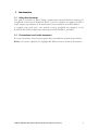
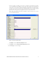
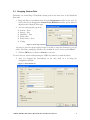
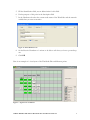
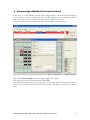
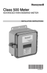
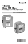
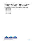
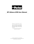
MICRO THERMO TECHNOLOGIES™
MT Alliance – WattNode Plus
Installation Guide
Document No. 71-MTA-1004-R1.2
No part of this publication may be reproduced,
stored in a retrieval system, or transmitted, in any
form or by any means, electronic, mechanical,
photocopying, recording, or otherwise, without
the prior written permission of Micro Thermo
Technologies.
© 1997-2015 by Micro Thermo Technologies.
All rights reserved worldwide.
Local Phone: (450) 668-3033 | Fax: (450)668-2695
Toll Free Canada: 1-888-664-1406 | Toll Free USA: 1-888-920-6284
www.sporlanonline.com/micro-thermo
Table of Contents
1
Introduction ........................................................................................................... 1
Using this document............................................................................................................. 1
Conventions used in this document ................................................................................... 1
2
Step by Step Procedure .......................................................................................... 2
2.1
Installation and Wiring of the unit ..................................................................................... 2
3
MT Alliance ............................................................................................................ 2
3.1
Adding WattNode Plus View (optional) ........................................................................... 2
3.2
Adding the Custom node WattNode Plus ........................................................................ 2
3.3
Dropping Custom Point ...................................................................................................... 6
3.4
On-Line and Wink ................................................................................................................ 8
3.5
Network variables ................................................................................................................. 8
4
Acknowledge a WattNode Plus test fail Alarm...................................................... 9
5
Revision History................................................................................................... 10
1.1
1.2
71-MTA-1004-R1.2 MT Alliance WattNode Plus Installation Guide.doc
i
1
Introduction
1.1 Using this document
This guide is intended for Micro Thermo Technologies trained technicians installing the
Continental Control System WattNode Plus™. It is not a complete user guide, but rather a
simple step-by-step summary of the instructions for the installation on the MT Alliance.
A complete user guide and a user manual covering specifically the operation of the
WattNode Plus™ are available in the following document: WnPlus 1_00UL.pdf
1.2 Conventions used in this document
For your convenience, several screen captures have been added to describe the procedures.
Bold text is used for emphasis or to highlight MT Alliance terms as found on the interface.
71-MTA-1004-R1.2 MT Alliance WattNode Plus Installation Guide.doc
1
2
2.1
Step by Step Procedure
Installation and Wiring of the unit
On the Y model neutral and phase A must be connected to power line and you should see
the service light while pressing the service button.
For more information see the WattNode Plus user’s guide (PUID 70-3RD-1003)
3
MT Alliance
After the physical installation, the configuration parameters must be loaded into the
controller.
3.1
Adding WattNode Plus View (optional)
1. You don’t have to be in configuration Mode.
2. In the Configure menu, select Views. The View Configuration window opens.
3. Click Energy in the Subsystem menu.
4. Select the view after witch you want the WattNode Plus view to be inserted.
5. Click the Insert after button. A new view without any images appears.
6. Type the name (PowerRoom) of the view in the View Name field.
7. Click the Change Image icon. The Open File dialog box appears. Select and open
the Image to get a graphic representation of the desired view if it exists (i.e. Service
Board.bmp):
8. If you wish, you can check the Zoom box. Thus, only custom point status will be
seen in the normal view when you place them on a view close up.
3.2
Adding the Custom node WattNode Plus
Figure 1 – Navigator Bar
1. In the Subsystem menu, select Energy or click the left menu of the navigator bar
and click on the Energy Subsystem.
2. In the Mode menu, select Configuration. When entering this mode, a components
toolbox appears in the bottom right corner of the window. It contains all the items
that can be placed in the view.
71-MTA-1004-R1.2 MT Alliance WattNode Plus Installation Guide.doc
2
3. Select the view by clicking on the View menu or on the right menu of the navigator
bar and click on the desired view name.
4. Drag and drop a node icon from the Components toolbox to the view. As soon as
the icon is dropped, the Node Definition window opens. Select in dropdown list
the custom node Node type the Unknown Manufacturer and Unknown Model.
Figure 2 – Node model selection
5. Click the OK button to finish or Cancel to start over.
To move an icon, select it while pressing the CTRL key and move it with the mouse.
Once the node is placed, it must be configured and associated with the controller.
1. Click the node icon. The Custom Node Information dialog box opens.
2. Select the Details tab.
71-MTA-1004-R1.2 MT Alliance WattNode Plus Installation Guide.doc
3
Figure 3 – Node Details tab
3. Type a unique name for the node (WattNode Plus) in the Identification field, the
Manufacturer name (CCS) and the node model and, if you wish, some information in
the Notes field.
4. Select the Commands/Status tab, uncheck “Supports Write To Flash”
5. Before installing it make sure you have powered on the WattNode Plus (see section
2.1)
Figure 4 – Node Commands/Status tab
6. In the Installation box, click the Install button.
7. The Install a Custom Node dialog box opens and prompts you to click the Service
button of the WattNode Plus. For manual entry, see the “Node Installation” manual.
Once the installation is completed, all the window buttons are activated.
For more information on the Testing and Maintenance Commands refer to the MT
Alliance – Node Installation Manual
8. To keep network traffic to an acceptable level click on “Network Variables” button
and set the following variables to the appropriate value
nciCtAmps_f set to current range max (ex: 800 for a 0-800A CT)
nciDemPerMins 5
nciEngyUpdtT 00:00:20
nciPwrUpdtT 00:00:20
nciReacUpdtT 00:00:20
71-MTA-1004-R1.2 MT Alliance WattNode Plus Installation Guide.doc
4
If only one phase is working you may have to enable the other phases by putting
“12” in nviCalSel then the number of active phase will be display by nviCal. Enter a
value from 1 to 3 in nviCal to enable that number of phases. Be very careful if doing
so. This is also the gate for Current sensor calibration and it can’t be undone. See the
WattNode Plus user’s guide in the Calibration section for more information.
If the value of nvoPower and nvoPF are negative it may be because one or more
CTs are installed wrong way.
Figure 5 – Network variables window
Click OK to close the Network Variables window.
9. Click OK to close the Custom Node Information window.
10. Click Accept to save the changes.
71-MTA-1004-R1.2 MT Alliance WattNode Plus Installation Guide.doc
5
3.3
Dropping Custom Point
Preferably you should drop a WattNode custom point in the same view as the WattNode
Plus node.
1. Drag and drop a CustomPoint icon from the Components toolbox to the view. As
soon as the icon is dropped, the Custom Point Definition window opens. Select in
dropdown list a Measure Point type.
2. You can select physical type from
¾
¾
¾
¾
¾
¾
Current – float
Energy – float
Frequency – float
Power- float
Power Factor – float
Voltage
Figure 6 – Point type selection
You need to select the proper physical type to be able to select the desired nvo (see the
table 1. The Time_stamp type variable is not available in ver 4.1 for the nvoPeakDemT..
3. Click the OK button to finish or Cancel to start over.
To move an icon, select it while pressing the CTRL key and move it with the mouse.
4. After you dropped the CustomPoint on the view, click on it to bring the
configuration window.
Figure 7 – Point Details tab
71-MTA-1004-R1.2 MT Alliance WattNode Plus Installation Guide.doc
6
5. Fill the identification field; use an abbreviation for this field.
6. Put the purpose of this point in the description field
7. In the Hardware tab select the custom node name of the WattNode and the network
variable that you want to monitor.
Figure 8 – Point Hardware tab
8. Set the Receive Heartbeat to 1 minute to be able to tell when you have a power drop
out.
9. Click OK
Here is an example of a view layout of the WattNode Plus and Measure points.
Figure 9 – Typical view in Alliance
71-MTA-1004-R1.2 MT Alliance WattNode Plus Installation Guide.doc
7
3.4
On-Line and Wink
When the WattNode Plus is on-line the Service LED is off continuously except at the
start and when we press the service button. If the Service LED is blinking the
WattNode Plus is uninstalled
When a wink command is sent to the WattNode Plus its service LED light for 15
seconds.
3.5
Network variables
All output network variables have a bandwidth control parameters that are called
Update Time (known in Lonworks as Max Send Time). There is one for each nvo
group in bold, default values is 5 seconds and can be changed for something between 0
to 18h. We suggest 20 seconds. For many nvos after a power up or a reset the
measured nvo is temporarily reset to 0 and will be updated at the end of the Update
Time while other nvos send the real value right away. The nvoPkDemand must be
polled as it is retransmitted after a reset or when it changes only.
Table 1
nvo Name
nciPwrUpdtT
nvoPowerSum
nvoPower[n]
nvoCurrent[n]
nvoVolts[n]
nvoFreq
87
57
57
48
66
75
Elapsed time
Power – float
Power – float
Current – float
Voltage
Frequency – float
Recom Max
Send Tm
20s
20s
20s
20s
20s
20s
nciEngyUpdtT
nvoEnergySum
nvoEnergy[n]
nvoReacEngySum
87
68
68
68
Elapsed time
Energy – float
Energy – float
Energy – float
20s
20s
20s
20s
0-18h
5s
5s
5s
Real value
Real value
Real value
nciReacUpdtT
nvoReacPwrSum
nvoReacPwr[n]
87
57
57
20s
20s
20s
5s
5s
0
0
nvoPFavg
99
20s
5s
Real value
nvoPF[n]
99
Elapsed time
Power –float
Power –float
Power factor –
float
Power factor –
float
20s
5s
Real value
nciDemPerMins
nvoDemand
8
57
count
Power –float
5m
5m
5-720m
5m
0
Not repeated
nvoPkDemand
nvoPeakDemT
57
84
Power –float
Time stamp
polled
new peak
new peak
Real value
Real value
SNVT
Physical Type
Must be
71-MTA-1004-R1.2 MT Alliance WattNode Plus Installation Guide.doc
Def. Max
Send Tm
0-18h
5s
5s
5s
5s
5s
Send On
Delta
Power
Up/Reset
0
0
0
0
Real value
8
4
Acknowledge a WattNode Plus test fail Alarm
Every hour or so MT Alliance test each node to make sure it is still powered and connected
to the network. A node test fail occur when the MT Alliance can’t communicate with the
node or the node does not work properly during MT Alliance test routine.
The acknowledgement of the WattNode Plus test fail Alarm is done as follow:
Figure 10 – Alarm acknowledging
Click on the Acknowledge button at the upper right of the screen.
Then enter your account and password and click OK.
The WattNode Plus button will stay red until it is fixed and the MT Alliance has made his
next auto test or until a manual node test has been done. This button is invisible in overview
mode.
71-MTA-1004-R1.2 MT Alliance WattNode Plus Installation Guide.doc
9
5
REV
0.0
0.1
0.2
0.3
0.4
1.0
1.1
1.2
Revision History
Description
Creation of the document from 71-MTA-1018-R2.0
Ready for revising
Revised by JFB
Final Revision
Publication
Logo changed
Cover page
71-MTA-1004-R1.2 MT Alliance WattNode Plus Installation Guide.doc
Revised by
RL
RL
RL
Date
01-mar-05
07-mar-05
17-mar-05
JG
RL
RL
ER
24-Mar-05
26-mai-06
27-Mar-11
27-Feb-2015
10