1
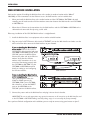
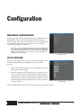
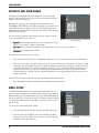
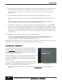
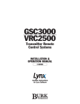
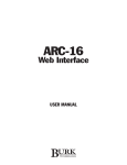
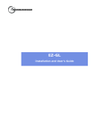
GSC/VRC
Web Interface
USER MANUAL
GSC/VRC Web Interface User Manual
REV D 07/06
Firmware Version 2.1.0.x
Copyright © 2006 Burk Technology, Inc. All rights reserved. No part of this manual may be reproduced in any form or by any
means without written permission from Burk Technology. Information in this manual is subject to change without notice.
Contents
INTRODUCTION ......................................................................................................................................1
Features and Benefits....................................................................................................................................................................1
System Requirements....................................................................................................................................................................1
Using a firewall for security .........................................................................................................................................................2
Unpacking........................................................................................................................................................................................2
Indicators and Connectors ..........................................................................................................................................................3
Contacting Burk Technology.......................................................................................................................................................3
INSTALLATION ........................................................................................................................................5
Initial Configuration.......................................................................................................................................................................5
Web Interface Installation ............................................................................................................................................................6
CONFIGURATION ....................................................................................................................................7
Web-Based Configuration............................................................................................................................................................7
TCP/IP Settings..................................................................................................................................................................................7
Security & User Names....................................................................................................................................................................8
Email Setup .........................................................................................................................................................................................8
Upgrading Firmware...........................................................................................................................................................................9
Advanced Tools ................................................................................................................................................................................10
OPERATION...........................................................................................................................................11
Connecting & Logging In...........................................................................................................................................................11
Default View...................................................................................................................................................................................11
Reviewing & Clearing Alarms ....................................................................................................................................................13
Email Alarm Notifications...........................................................................................................................................................13
Using the Alarm Ticker ...............................................................................................................................................................13
Remote/Local Mode....................................................................................................................................................................13
Disconnecting...............................................................................................................................................................................14
Using the Web Interface to Connect with Lynx 5................................................................................................................14
TROUBLESHOOTING.............................................................................................................................15
SPECIFICATIONS & WARRANTY............................................................................................................17
CUSTOMER SUPPORT: 978-486-3711 • [email protected] • www.burk.com
iii
iv
GSC/VRC WEB INTERFACE USER MANUAL
Introduction
The GSC/VRC Web Interface adds TCP/IP control to the GSC3000 and VRC2500 transmitter remote control
systems, making data from your remote site available from your web browser. Depending on your requirements
and the way your network is set up, you can access the Web Interface from within your LAN/WAN, or you can
allow users to log in from anywhere on the Internet. The Web Interface will also facilitate TCP/IP-based connections between the GSC3000 or VRC2500 and a computer running Lynx 5. This reduces the need for serial connections between the PC and the remote site.
FEATURES AND BENEFITS
•
•
•
•
•
•
Web-based interface for LAN/WAN access
Site access from the Internet (if desired)
Email alarm notifications via email or SMS to pagers, PCs, cell phones, PDAs, etc.
Multi-client support for large operations
Three tiers of user privileges
Supports Lynx 5 connections over TCP/IP
SYSTEM REQUIREMENTS
LAN/WAN Requirements
•
•
•
•
10BaseT LAN connection at the studio or transmitter site
Static IP address assignable to the Web Interface
For site access from the Internet, the IP address must be public
Broadband ISP service for access from the public Internet
Note: If the LAN connection is at the studio site and the GSC3000 or VRC2500 is located at a remote transmitter
facility, the Web Interface requires a full-time bi-directional serial link (19.2Kbps) between the studio and transmitter.
IMPORTANT! While security features are built in, we recommend using a firewall. Like most network devices, the Web
Interface is not designed to duplicate the security features provided by a firewall.
GSC3000 or VRC2500 firmware
•
Version 5.0 or higher
CUSTOMER SUPPORT: 978-486-3711 • [email protected] • www.burk.com
1
INTRODUCTION
For Web-based Monitoring and Control
•
•
•
•
Windows®-based computer with Internet Explorer 5 or higher or Mozilla Firefox browser
Sun Microsystems Java Virtual Machine version 1.5 or higher
56K Internet access or faster (broadband connection recommended)
1024 x 768 screen resolution or higher recommended
IMPORTANT! If Java Virtual Machine version 1.5 or higher is not installed, you may encounter display issues when connecting via a Web browser. Make sure the correct version is installed on the computer(s) you are using to view your site
data.
Note: While 56K dialup access will work for a client connection to the Web Interface, the Web Interface itself
requires broadband (DSL or faster) speeds to connect to your LAN/WAN.
For TCP/IP connectivity using Lynx software
•
Lynx software version 5.0 or higher
USING A FIREWALL FOR SECURITY
It is always a good idea to install the Web Interface behind a firewall. While the Web Interface has built in security features, a firewall affords a level of security beyond what most network devices are designed to provide. Your
company's network administrator will usually need to set this up for you.
When installing a publicly addressable Web Interface behind a firewall, you will need to open two ports on the
firewall and forward them to the Web Interface. One port should provide access to port 80. The other should be
the TCP port designated for the Web Interface. 4095 is the default, but each Web Interface should be assigned
a unique TCP port. For added security, do not forward port 80 directly to the Web Interface, but instead designate a different port for Web access and route that different port to port 80. In this case, users connecting to
the Web Interface from a Web browser will need to type the IP address followed by a colon (:) and the port number that matches both the Web Interface TCP port and the port on the firewall.
Note: Network configurations and characteristics vary widely. The above method is not a requirement, but rather
one way to establish reasonable network security. Always consult your network administrator for requirements specific to your application.
UNPACKING
The GSC/VRC Web Interface includes the following:
•
•
•
•
2
Power Cord
DB-9 to DB-9 Serial Cable
GSC/VRC Web Interface User's Manual
Lynx 5 software CD (includes license for two PCs)
GSC/VRC WEB INTERFACE USER MANUAL
INTRODUCTION
INDICATORS AND CONNECTORS
Before you begin setup and configuration, take a moment to familiarize yourself with the indicators and connectors on the Web Interface. For specifications, see page 17.
eb
W
te
In
r fa
ce
Power LED
Indicates AC power connection the Web Interface.
Power Connector
100-240 VAC, 50/60Hz, without manual switching.
COMPUTER Port
Accepts null modem cable DB-9F connector for initial configuration using a PC and HyperTerminal connection.
GSC/VRC Port
Used to connect the Web Interface to the GSC3000 or VRC2500, using either a direct null modem cable connection or a remote serial connection via full-time modem. The LED to the right of the port indicates a good
connection to the site.
ETHERNET Port
Connects the Web Interface to a 10BaseT LAN/WAN. You will need a CAT5 cable with RJ-45 connectors. The
right-side LED indicates a connection to the LAN/WAN, and the left-side LED indicates data activity.
CONTACTING BURK TECHNOLOGY
Customer Support
Visit the Support section of our website at www.burk.com for troubleshooting tips, documentation and downloads. If you still need help, please contact Customer Support:
Phone:
Fax:
Email:
978-486-3711
978-486-0081
[email protected]
Sales
For information on our full line of remote control systems and accessories, please visit us online at
www.burk.com, or contact a sales representative:
Phone:
Email:
800-255-8090 (Main Sales Office)
800-736-9165 (Broadcast Sales)
609-886-1733 (Government & International Sales)
[email protected]
CUSTOMER SUPPORT: 978-486-3711 • [email protected] • www.burk.com
3
4
GSC/VRC WEB INTERFACE USER MANUAL
Installation
INITIAL CONFIGURATION
Before connecting the Web Interface to your LAN/WAN, you need to set up basic connection settings, such as
the IP address. Initial configuration requires use of a terminal application, such as HyperTerminal, and a direct PC
connection to the Web Interface. Once the initial configuration is complete, you will be able to edit the configuration settings over the LAN/WAN using your web browser (see page 7).
Note: During initial configuration, Web Interface access from your browser or Lynx software is disabled.
To complete the initial configuration process:
1. Connect your PC to the Web Interface COM port marked COMPUTER. Open a HyperTerminal session
configured for 115.2Kbps, 8 bits, no parity, 1 stop bit. When the configuration session loads, you will see
these choices:
1. Setup Web Interface
2. Perform System Test
3. Network Information
Press 1 followed by <ENTER> to begin setup.
2. Enter your TCP/IP settings where prompted, pressing <ENTER> after each field. You will be asked to confirm each entry.
3. Enter a new administrator password where prompted. Do not leave it blank.
4. Now you can disconnect the PC from the Web Interface CONFIG port and install the Web Interface in its
permanent location and connect using your browser and/or Lynx software.
Note: Now that the Web Interface has an IP address and administrator password, you will be able to make future
configuration changes using your web browser. If your network settings change, or if you forget your password, you
can use HyperTerminal to connect at anytime and reset or edit the settings.
CUSTOMER SUPPORT: 978-486-3711 • [email protected] • www.burk.com
5
INSTALLATION
WEB INTERFACE INSTALLATION
You have the option of installing the Web Interface at the studio (or another location with a 10BaseT
LAN/WAN), or if the transmitter site has Ethernet access, the Web Interface can be installed there.
•
When you install the Web Interface at the studio location and the GSC3000 or VRC2500 is located
remotely, you will need to make a full-time modem connection between the Web Interface and GSC3000
or VRC2500 site.
•
When there is Ethernet at the transmitter site, the Web Interface and the GSC3000 or VRC2500 can be
collocated and connected directly using a serial cable.
Either way, installation of the GSC/VRC Web Interface is straightforward:
1. Install the Web Interface in an equipment rack or another suitable location.
2. Plug one end of a CAT5 Ethernet cable into the ETHERNET port on the Web Interface and make sure the
other end of the cable connects the Web Interface to your network.
If you are installing the Web Interface
at the studio: Connect one end of a
serial modem cable (provided with your
GSC3000 or VRC2500 system) to the
GSC/VRC port on the Web Interface.
Connect the other end to the full-time
modem. Verify that the full-time
modem at the transmitter site is connected and functioning properly with
the GSC3000 or VRC2500. See the
GSC3000 or VRC2500 manual for
details on setting up and configuring
the full-time modems.
If you are installing the Web Interface
at the transmitter site: Connect a serial
cable (provided) from either the
COM1 or COM2 port on the
GSC3000, COM 1 on a GSC3000
Voice Interface, or from the DIRECT
port on the VRC2500, to the
GSC/VRC port on the Web Interface.
Studio Connection
Transmitter (Local) Connection
3. Connect the power cord to the Web Interface and plug it into an electrical outlet.
IMPORTANT! Be sure to take appropriate surge protection measures on all connections to the Web Interface and
to the GSC3000 or VRC2500. Damage caused by voltage surges is not covered by the factory warranty.
Once you have finished configuration and installation, you are ready to connect using your browser or Lynx 5.
6
GSC/VRC WEB INTERFACE USER MANUAL
Configuration
WEB-BASED CONFIGURATION
As long as you have already completed the initial configuration of the
Web Interface using a connection via HyperTerminal (see page 5),
TCP/IP settings, email setup, user setup and access to advanced tools
are available by clicking on the configuration icon in the toolbar.
System-level privileges are required.
Note: When you are editing the Web Interface settings via the Web browser, you can click the Reset button to discard your edits and redisplay the
previously saved settings. However, once you save the settings to the Web
Interface, the Reset button will not revert your changes; you will have to
manually restore the settings.
Configuration Home
TCP/IP SETTINGS
After the initial configuration is complete, the TCP/IP settings can be
viewed and updated from the Configuration page on the Web
Interface.
1. Click on the TCP/IP Settings link on the Configuration page to
modify your network settings.
2. Enter the appropriate TCP/IP settings where prompted. If you
are not sure of the correct settings, check with your network
administrator. The TCP port and HTTP port settings allow you
to give the Web Interface a unique TCP port number and to use
a firewall and port mapping to operate on an HTTP port other
than 80, if desired.
TCP/IP Settings
Click the Submit button to upload TCP/IP setting changes to the Web Interface.
CUSTOMER SUPPORT: 978-486-3711 • [email protected] • www.burk.com
7
CONFIGURATION
SECURITY AND USER NAMES
Clicking the Security link allows you to update the Site Password
stored on the Web Interface, and to set up new passwords and privileges for new or existing users.
Remember that you are not changing the site password on the
GSC3000 or VRC2500 unit, but rather updating the password used
by the Web Interface to log in to the unit. You should only have to
modify the site password if the site password itself has been changed
using the Lynx software.
For user names, passwords and privileges, you can assign up to ten
users. The available access levels are:
Security Settings
•
System: Views readings and alarms, issues commands and runs
macros, clears alarms, changes configuration.
Operator: Views readings and alarms, issues commands and runs macros, clears alarms
•
Observer: Views readings and alarms
•
To modify the site password or user setup:
1. Click on the Security link on the Configuration page to access the site password and user information.
2. Enter user names and passwords, and choose an access level for each user. Passwords can have up to 50
characters, and all printable characters are allowed. Complex passwords are strongly recommended, especially if the Web Interface is assigned a public IP address. It is also a good idea to change passwords as
frequently as necessary to reduce the possibility of unauthorized access. Note: Each user must have a
password. While it is possible to save a blank password for a user, login attempts will fail unless the user
enters a password.
Click the Submit button to upload new security settings to the Web Interface.
Note: The Admin user cannot be deleted, but you may edit the password as desired.
EMAIL SETUP
The GSC/VRC Web Interface will report alarm notifications to cell
phones, pagers, computers or any other device that receives email or
SMS text messages. The Web Interface will send email notifications to
the email addresses you specify, and you can choose between detailed
or abbreviated alarm reports, depending on the type of device receiving the email.
To set up your email notification settings:
1. Click the Email link on the Web Interface Configuration page.
2. Enter the name of the SMTP server you would like the Web
Interface to use. The SMTP server must be accessible from the
IP address of the Web Interface.
8
Email Setup
GSC/VRC WEB INTERFACE USER MANUAL
CONFIGURATION
3. Enter a reply-to email address where prompted. The reply-to address will appear in the From: field of each
email notification, and messages to any undeliverable email addresses will be directed to this address.
Note: Even if you have no need to receive undeliverable messages, the reply-to field must be filled in for email notifications to work.
4. If your ISP requires SMTP authentication, enter the user name and password for the account.
5. Enter up to ten email addresses to receive alarm notifications. All emails will be sent to the entire list at
once.
Tip: For notification to more than ten users, talk to your network administrator about setting up a distribution list
and enter the address for the distribution list in the email settings for the Web Interface.
8. If the device receiving the email is a pager, cell phone or other text messaging device, check the PAGER
box next to the email address so that outgoing emails contain only the alarm message. SMS devices are
limited to a certain character length, and smaller messages are easier to read on most SMS device displays.
If the email is directed to a PC or other non-SMS device, leave the PAGER box unchecked, and the email
will include the type of alarm (warning or critical); timestamp; site name, unit number and channel; and the
alarm message.
Click SUBMIT to change the email notification settings to the Web Interface.
Note: Email alarm notifications are only sent for new alarms that occur when the Web Interface is powered up and
connected to a GSC3000 or VRC2500. Alarms that are pending at the time the connection is made will not be
reported via email, but are displayable by logging in and clicking the alarms icon
IMPORTANT! For the Web Interface to send SMS text messages to cell phones, an email-based SMS service is required.
Contact your wireless service provider to verify availability, cost and instructions for use.
UPGRADING FIRMWARE
To update the firmware in Web Interface units that have firmware version 2.0 or higher, visit the support section of Burk Technology’s web
site at www.burk.com. Available firmware files will be listed on the support page for the GSC/VRC Web Interface. Choose the file to download and save it to your computer.
After downloading the file to your PC, log in to the Web Interface and
click on the Configuration icon in the toolbar. Click on the update
firmware link, and follow the on-screen instructions after the Update
Firmware page loads.
To verify the firmware version loaded in your Web Interface, click the
Configuration icon and following the link for View System Log. The
header on the system log contains the firmware version.
Uploading Firmware
Note: If your system has firmware version 1.x, please send email to [email protected] for details on upgrading your
firmware.
CUSTOMER SUPPORT: 978-486-3711 • [email protected] • www.burk.com
9
CONFIGURATION
ADVANCED TOOLS
The advanced configuration tools provide access to the Web Interface system log and firmware update utility,
and allow users to clear the Web Interface configuration cache or restart the Web Interface. Choose a topic on
the left for more information.
View the System Log
Use this link to display the Web Interface System Log, which includes events such as logins, connections and
restarts, as well as system warnings and errors.
Note: Upon connection, the Web Interface synchronizes time with the GSC3000 and VRC2500 site. Events occurring
before synchronization is complete are time-stamped January 1, 2000. Once the times are matched, subsequent
events in the system log are logged based on the time stored on the GSC3000 or VRC2500. You can adjust the time
using the Lynx software.
The System Log is capable of storing up to fifty events at once, in circular fashion. After fifty events are logged,
new events will overwrite the oldest events.
The System Log header includes the following system information:
•
•
•
•
Firmware Version
Up Time
Available Memory
Available Disk Space
Restart the Web Interface
During normal operation, you will not need to restart the Web Interface. However the restart link is available as a
troubleshooting tool. It may take a few moments for the Web Interface to restart. You will be prompted to log in
again after the Web Interface comes back online.
Clear the Cache
The Web Interface stores site information in memory so that it may be displayed onscreen without downloading
the data again. The Clear the Cache link is available as a troubleshooting tool. Click the link to delete the stored
site information. The Web Interface will re-download the information from the GSC/VRC. The reload process may
take a few minutes.
10
GSC/VRC WEB INTERFACE USER MANUAL
Operation
CONNECTING & LOGGING IN
To connect to a Web Interface site, enter the IP address or
domain name of the Web Interface in the address bar of your
web browser. The IP address is first set up during initial configuration (see page 5). The IP address can later be changed
using Internet Explorer, or again using HyperTerminal as
described previously.
When the login screen appears, enter your user name and
password and click the Login button. If this is the first time
anyone has logged in to the Web Interface, use the Admin
user account and the password you set up during initial configuration. You will be able to add new users after you log in
(see page 8).
Note: The GSC/VRC Web Interface supports multi-client capability, allowing up to ten (10) simultaneous connections through
a browser, Lynx 5, or a combination of the two.
Login Screen
DEFAULT VIEW
After you log in, the Default View is the first screen displayed.
It may take a few moments to load, and the progress bar at
the top of the screen will appear as alarm data is downloaded.
Important! The Web Interface was designed for use with Microsoft
Internet Explorer 5.0 or higher, or Mozilla Firefox. Version 1.5 of
Sun Microsystems Java Virtual Machine is required (www.java.com
<http://www.java.com>). Other configurations may work, but Burk
Technology recommends and supports the above versions.
Default View
CUSTOMER SUPPORT: 978-486-3711 • [email protected] • www.burk.com
11
OPERATION
Default View at a Glance
The Web Interface default view displays metering values, status conditions and command buttons for each
VRC2500 or GSC3000 I/O unit connected at the site, one I/O unit at a time. Each I/O unit has a dedicated
page in the Web Interface, and you can change the unit being viewed by selecting from the drop down list in the
upper right corner of the screen. The top left of each page displays the site name.
Note: If you are using the Web Interface to connect to a VRC2500 unit, only one unit is selectable from the dropdown list (the VRC2500 I/O unit, not the Voice Interface unit).
The toolbar at the top of the page shows the alarm count, provides access to the alarm list, and allows users
with appropriate privileges to access macros and edit configuration. There are also icons to access this help
menu and to log off.
At the bottom of the screen is the scrolling alarm ticker, which displays alarm conditions. For more information on
the alarm ticker, see page 13.
Important! Your computer’s screen resolution affects the amount of information that can be displayed on the screen
without scrolling. Fro best results, Burk Technology recommends a minimum 1024x768 screen resolution, with the Web
browser window maximized or displayed in full-screen mode (press F11).
Monitoring Site Readings
Background colors in each meter value and the colors of the LED status indicators are determined by the I/O
unit configuration, which is set up in Lynx and stored on the I/O units. See the GSC3000 or VRC2500
Instruction Manual for more details.
Readings for sixteen channels are displayed at once. If you have a GSC3000 operation with more than one I/O
unit installed, use the drop down list at the top right of the screen to select the unit containing the desired
channels.
Note: The values shown for each metering channel are displayed based on the calibration constant set up in Lynx and
stored on the VRC2500 or GSC3000 itself. If the calibration needs to be changed, use the Lynx 5 software to connect to the site and edit the calibration for the desired unit and channel (see the GSC3000 or VRC2500 manual for
more information). To view the newly calibrated values, use the Refresh feature in your browser.
Issuing Commands
Command buttons are positioned in two columns on the right side of the screen, and clicking on the command
button results in a contact closure on the associated channel. Commands issued from the Web Interface respond
to the command durations that were set up in Lynx and saved to the I/O unit. Command buttons will not appear
if no command label has been assigned in Lynx.
Click the button associated with the desired command channel to issue a command. Users with “Observer” privileges are not able to issue commands.
Running Macros
To run (or stop) macros from the Web Interface, click the Macros icon next to the alarm indicator in the toolbar.
This opens the macro window, which displays a list of macros. The status column indicates which macros, if any,
are running. All macros for an individual I/O unit are displayed in the macro window. To view macros for a different I/O unit at the site, choose the unit from the drop-down list.
Run a macro by clicking the run icon next to the macro. The status column will show a “running” icon while the
macro executes. To stop a macro that is currently running, click the stop icon.
12
GSC/VRC WEB INTERFACE USER MANUAL
OPERATION
Note: The “running” icon may not appear if the macro runs for a very brief duration.
REVIEWING AND CLEARING ALARMS
One the left side of the toolbar at the top left of the screen, the
alarm indicator notifies users of any alarms at the site. The link
reads “0 Alarms Pending” when there are no alarms to report.
When alarms are present, the indicator turns red and displays a
running tally of all alarms at the site. The alarm count will increment as each new alarm is reported.
Note: While the default view shows metering, status and command
channels for only the selected I/O unit, the alarms link reports the
number of current alarms for the entire site. This allows operators to
receive alarm notifications for all units, even though only one is displayed.
To view alarms, click the alarm indicator. Alarms are displayed in a new window. Once the alarm window is
opened, you may clear alarms by selecting the desired unit from the drop-down list and then click the Clear
Alarms button.
IMPORTANT! Clearing alarms from the Web Interface permanently erases them from the GSC3000 or VRC2500.
Although the alarms are recorded in the Lynx site log, they will no longer be reported by the Web Interface, and they will
not be reported via Lynx software or a Voice Interface session.
EMAIL ALARM NOTIFICATIONS
When you specify an SMTP server during the configuration process (page 5), email alarm notifications will be
sent to all of the email addresses you entered during Email Setup as soon as they are received by the Web
Interface. You can add, remove or modify the email list by clicking the configuration link at the top of the screen
and going to Email setup. System privileges are required to edit the email list.
Note that email notifications are only sent for newly registered alarms. If there are already alarms pending when you
connect the Web Interface to the GSC3000 or VRC25000, the preexisting alarms will not be emailed.
USING THE ALARM TICKER
At the bottom of the screen, a scrolling ticker displays alarm conditions. When the Web Interface first loads,
alarms are displayed in yellow. Once the alarms have been displayed once, they are shown in white. You can click
on the ticker to stop it or drag it right or left to partially advance/rewind it.
REMOTE/LOCAL MODE
When I/O units are toggled from remote to local mode, the Web Interface will disable the command channels
and macro functions. Meter and status readings will remain updated, but you will not be able to execute commands. The command and macro buttons will be grayed out as an indication that the selected unit is in local
mode.
Commands and macros will automatically become active when the site is returned to Remote mode.
Note: You can only toggle between remote and local mode is only available at the site, from the front panel of the
I/O units. You cannot use the Web Interface to toggle between remote and local mode.
Using the Alarm Ticker
CUSTOMER SUPPORT: 978-486-3711 • [email protected] • www.burk.com
13
OPERATION
DISCONNECTING
Disconnecting after a Web Interface session prevents unauthorized access to the site. To disconnect from the
Web Interface, close the web browser or click the Log Out link to return to the login screen.
USING THE WEB INTERFACE TO CONNECT WITH LYNX 5
In addition to web-based site access, the Web Interface supports TCP/IP connections from Lynx 5. This allows a
PC running Lynx 5 to connect to a GSC3000 or VRC2500 over the LAN or Internet without relying on a serial
connection or dedicated computer at the remote site.
There are no Web Interface configuration changes required to make a direct TCP/IP connection with Lynx 5, but
you will need to edit the Site settings using the Lynx 5 Site Wizard. If you are setting up the site for the first
time, follow instructions in the GSC3000 or VRC2500 manual that shipped with Lynx 5.
To connect with Lynx 5 through the Web Interface, via TCP/IP:
1. Connect to the site and click the Edit Site icon in the toolbar. This opens the Site Wizard.
2. In the Site Wizard, on the Primary Connection and/or Backup Connection screens, select the "Web
Interface" option.
3. Enter the IP address of the Web Interface, and verify that the TCP Port matches the TCP Port you specified during initial configuration (see page 5). The default TCP port is 4095.
4. Click Finish to enter your connection settings (see Chapter 2 of the GSC3000 or VRC2500 manual for
more information).
After you set up the site in Lynx 5 and initiate a connection, the Web Interface will send the GSC3000 or
VRC2500 data via TCP/IP to the Lynx 5 computer. Lynx 5 operations using a Web Interface connection are no
different from using a serial connection.
Note: The GSC/VRC Web Interface supports a total of ten (10) simultaneous connections, whether the connections
are with Internet Explorer, Lynx 5 or a combination of both.
14
GSC/VRC WEB INTERFACE USER MANUAL
Troubleshooting
Most connection errors can be traced to improper network settings specified during initial configuration, or to
security conflicts with a local firewall. Check with your network administrator or ISP to make sure all settings are
correct, and verify that your firewall is not preventing access.
If you are encountering display issues, double check that the latest version of Java is installed. You can download
Java free from www.java.com. The minimum requirement is version 1.5. The Web Interface supports Internet
Explorer version 5.0 or higher and Mozilla Firefox.
For more troubleshooting tips, please visit the support section of the Burk Technology web site at
www.burk.com.
Burk Technology customer support is available by email or telephone Monday-Friday from 9AM to 5PM ET. Send
email to [email protected], or call 978-486-3711.
CUSTOMER SUPPORT: 978-486-3711 • [email protected] • www.burk.com
15
16
GSC/VRC WEB INTERFACE USER MANUAL
Specifications & Warranty
SPECIFICATIONS
Dimensions:
19" (48.3 cm) W x 10" (25.4 cm) D x 1.75" (4.45 cm) H
Operating Temperature:
0 to 50° C
Power Requirements:
100 to 240 VAC, 50/60Hz; 20W
Rear Panel Connections:
VRC/GSC Serial Port:
DB-9 serial port with link status LED for direct connection or full-time modem link to the GSC3000 or
VRC2500
COMPUTER Serial Port:
DB-9 serial port for PC-based configuration
ETHERNET Port:
10BaseT Ethernet port connects to LAN/WAN. LEDs show link status and activity
All specifications subject to change.
CUSTOMER SUPPORT: 978-486-3711 • [email protected] • www.burk.com
17
SPECIFICATIONS & WARRANTY
WARRANTY
Burk Technology, Inc. warrants the GSC/VRC Web Interface to be free of defects in materials and workmanship
for a period of 24 months from the date of purchase. Equipment will be repaired or replaced at the option of
Burk Technology and returned freight prepaid to the customer. Damage due to abuse or improper operation or
installation of the equipment or caused by fire or flood or harsh environment is not to be covered by this warranty. Damage in shipping is not the responsibility of Burk Technology. A return authorization must be obtained
before returning any equipment. Materials returned under this warranty must be shipped freight prepaid and
insured in the original shipping carton or suitable substitute to Burk Technology, 7 Beaver Brook Road, Littleton,
MA 01460. Repairs not covered under this warranty will be made at prevailing shop rates established by Burk
Technology, Inc.
THE WARRANTY SET FORTH ABOVE IS IN LIEU OF ALL OTHER WARRANTIES, EXPRESS OR IMPLIED, INCLUDING BUT NOT LIMITED TO THE WARRANTIES OF MERCHANTABILITY AND FITNESS FOR A PARTICULAR PURPOSE. BURK TECHNOLOGY, INC. SHALL NOT BE LIABLE TO ANY PARTY FOR ANY INCIDENTAL, SPECIAL,
INDIRECT OR CONSEQUENTIAL DAMAGES ARISING FROM THE USE OF THIS EQUIPMENT.
18
GSC/VRC WEB INTERFACE USER MANUAL