1
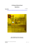
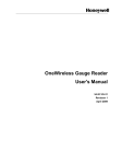
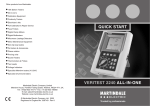
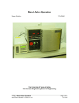
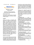
RCA Cleanup Hood Operations
Roger Robbins
Arnold Duenes
2/15/2006
The University of Texas at Dallas
ERIK JONSSON SCHOOL OF ENGINEERING
DOCUMENT TITLE: RCA Cleanup Hood Operations
AUTHORS: Roger Robbins and Arnold Duenes
6/2/2006
Page 1 of 32
RCA Cleanup Hood Operations
Roger Robbins
Arnold Duenes
2/15/2006
Table of Contents
RCA Cleanup Hood Operations ........................................................................................ 4
Introduction ................................................................................................................... 4
Description .................................................................................................................... 4
Feature Details.............................................................................................................. 5
Control Panel ............................................................................................................ 5
DI Water ................................................................................................................ 5
Exhaust ................................................................................................................. 6
Machine Start/Stop................................................................................................ 7
EMO Button........................................................................................................... 7
Audio Enunciator ................................................................................................... 7
Touch Screen ........................................................................................................ 7
Process Features ...................................................................................................... 8
DI Water Sink ........................................................................................................ 8
N2 Gun and DI Water Spray .................................................................................. 8
Chemical Process Tanks....................................................................................... 9
Pirahana Acid Tank ........................................................................................... 9
SC-1 Clean Up Tank ......................................................................................... 9
SC-2 Clean Up Tank ....................................................................................... 10
Buffered Oxide Etch Tank ............................................................................... 10
Cascade DI Water Rinse Tanks ...................................................................... 11
HF Acid Antidote ................................................................................................. 12
Acid Neutralization Tank ..................................................................................... 13
Operating Software ..................................................................................................... 13
Overview ................................................................................................................. 13
Login.................................................................................................................... 14
Timer Operation .................................................................................................. 14
Neutralization System ......................................................................................... 15
Rules of Operation ...................................................................................................... 17
Conclusion .................................................................................................................. 17
Appendix A...................................................................................................................... 18
Neutralization: Staff Procedure ...................................................................................... 18
Purpose....................................................................................................................... 18
Notes ....................................................................................................................... 18
Neutralization Procedure Details................................................................................. 18
Introduction ............................................................................................................. 18
Neutralization Preliminaries .................................................................................... 18
Plumbing Diagram Screen ...................................................................................... 19
Neutralization Parameters....................................................................................... 20
Caustic Pump Setup ............................................................................................... 23
Neutralization Procedure......................................................................................... 24
Appendix B...................................................................................................................... 26
DOCUMENT TITLE: RCA Cleanup Hood Operations
AUTHORS: Roger Robbins and Arnold Duenes
6/2/2006
Page 2 of 32
Theoretical Neutralization Chemistry .......................................................................... 26
Neutralization Chemistry ............................................................................................. 26
Chemical Definitions ............................................................................................... 26
Mole..................................................................................................................... 26
Gram-Equivalent Weight ..................................................................................... 26
Normality ............................................................................................................. 26
Density ................................................................................................................ 27
Concentration ...................................................................................................... 27
Theoretical Background .......................................................................................... 28
Appendix C...................................................................................................................... 31
Practical Neutralization Calculations........................................................................... 31
Chemical Calculations............................................................................................. 31
Appendix D...................................................................................................................... 32
Detailed RCA Process Setup Procedure .................................................................... 32
Introduction ............................................................................................................. 32
Recipes ............................................................................................................... 32
DOCUMENT TITLE: RCA Cleanup Hood Operations
AUTHORS: Roger Robbins and Arnold Duenes
6/2/2006
Page 3 of 32
RCA Cleanup Hood Operations
Roger Robbins
Arnold Duenes
2/15/2006
C:\Mydocuments\CleanRoomGeneral\Equipment\Hoods\RCA\RCAcleanupHoodOperation.doc
Introduction
This document describes the Clean Room’s new 8 foot RCA Cleanup Acid Hood
from Leatherwood Plastics, Inc., of Lewisville, Texas. This hood is intended to be our
special purpose starting semiconductor substrate cleanup acid hood. It is anticipated
that this process will use a significant amount of chemical resource, therefore it will be
set up to run on day per week. We fondly call it the RCA Hood, but it actually has a real
name: “HR01.”
Description
The RCA hood is constructed of a chemical and fire resistant white plastic,
(PVCC), with a 5.5 by 2.6 foot perforated work surface. Features of the hood include at
the work deck level a De-Ionized water sink with a recirculating gooseneck faucet – Note
that this sink drains into the normal sewer lines, so absolutely no acid can be disposed
of in this sink. Other features include the 3 main RCA cleanup process chemical baths,
a temperature controlled etch bath and two cascade DI water rinse tank systems. The
cascade DI water rinse tanks consist of two tanks for each system where fresh DI water
is supplied to the “Final” rinse tank and then overflowed into the “First Rinse” tank and
finally drained away. This allows a two stage rinse operation after exiting the acid baths.
Temperatures of all the acid baths can be read on the touch screen control panel. The
acid baths drain into a 30 gallon dilution and neutralization tank under the hood deck.
This has an active pH monitor and a caustic chemical (Sodium Hydroxide) supply for
automatic neutralization. The tank is initially filled to 55% of capacity with DI water to
dilute the acids and when neutralization is complete, the contents are pumped into the
building acid drain system.
The hood is controlled by a solid state controller with a touch screen control
panel user interface located on the right side of the hood. There are 4 process timers on
the front panel below the work surface.
Alarms are handled by the upper portion of the right hand side control panel.
The Big Red emergency off button is also located prominently on this panel. Exhaust is
monitored by a Photohelic differential pressure gauge on the left side of the front panel
below deck level. An alarm will go off if the hood exhaust is out of spec – this would be
the time to notify clean room staff and leave clean room since any acid vapors will drift
back out into the clean room air and recirculate throughout the clean room.
DOCUMENT TITLE: RCA Cleanup Hood Operations
AUTHORS: Roger Robbins and Arnold Duenes
6/2/2006
Page 4 of 32
Control Panel
Pirahna
Bath
DI water
faucet
and Sink
RCA
Clean
SC1
#1 DI Rinse Tanks
RCA
Clean
SC2
HF Etch
Tank
#2 DI Rinse Tanks
Touch Screen
Process
Timers
Exhaust
Photohelic
Neutralization system
Figure 1. RCA Cleanup Hood identifying the principal operating features
Feature Details
Control Panel
The control panel is shown in Figure 2 with labels. This panel is composed of
two segments: 1) a section of actuator buttons and indicator lights, and 2) a touch
screen linked to a microprocessor for controlling the operation of the hood. These will
be described in detail in the following sections.
DI Water
The hood has a recirculating de-ionized water plumbing system to prevent
Touch
stagnant
water from growing microorganisms and contaminating the purity of the water.
Screen
There is a monitor readout of this condition at the top of the control panel that displays
the resistivity of the water in meg ohms. The nominal value of good DI water is 18.1
meg ohms or better. If the value has slipped below the 17 meg ohm level, an alarm will
DI Water
Gun
Exhaust
DOCUMENT TITLE: RCA
Cleanup Hood Operations
Pressure
AUTHORS: Roger Robbins
and Arnold Duenes Process Timers
Gauge
Start & Stop Buttons
6/2/2006
Page 5 of 32
N2 Gun
sound. Please notify the clean room staff and if this would impact your work, discontinue
processing your work in this hood.
DI Water Condition Meter
(Meg Ohms)
Loss of Exhaust Indicator Light
Hood Start Button
Audio Alarm Enunciator
Emergency OFF Button
Alarm Silence Button
Hood Power off Button
Figure 2. Hood Control Panel details.
Figure 3. Photohelic Exhaust pressure
gauge (left), and alarm horn (right)
Exhaust
The photohelic pressure gauge, Figure 3, measures the exhaust pressure in the
exhaust line above the hood and if the pressure falls out of the acceptable range, it will
trigger the alarm horn (Figure 3), which will then complain very loudly and light up the
red alarm light on the control panel, Figure 2. If this happens, quickly bring your work to
a safe conclusion and discontinue the use of the hood. Also immediately notify clean
room staff. There may be a general loss of exhaust requiring clean room evacuation.
Follow staff direction. By the way, the exhaust alarm cannot be silenced except by
shutting off the main power to the hood. Do not attempt to change the photohelic
pressure gauge set points!
DOCUMENT TITLE: RCA Cleanup Hood Operations
AUTHORS: Roger Robbins and Arnold Duenes
6/2/2006
Page 6 of 32
Machine Start/Stop
The green “HOOD START” button on the control panel turns on the electricity to
the hood functions. The Red “MACHINE STOP” button turns off “most” of the electricity
to the hood. The hood is generally left “ON” all the time. This control is used when
service or problem diagnostic is required.
EMO Button
The EMergency Off button is used if the hood is having an electrical problem that
portends of immediate emergency. If there is smoke coming from the insides or the
chemical baths are overheating, etc. Please don’t hesitate to use this button. If you
have had to push the EMO button, please notify Clean Room Staff immediately!
Audio Enunciator
The audio enunciator is a piezoelectric beeper that announces either a nonemergency fault or the completion of a timed event. There is a convenient yellow alarm
silencer button which you can use to cause immediate cessation of the annoying beeps.
However, please make sure that the cause of this alarm is corrected before leaving the
hood. The identity of an alarm can be found by looking at the “Alarms” log screen
chosen from the “Main” touch screen page. Notify Clean Room staff if necessary.
Touch Screen
The Touch Screen is the user interface for
the microprocessor controller for the hood. This
controller has a password and multiple display
screens for monitoring and controlling the hood.
This is where the acid dump catch tank is
monitored and dilution and neutralization
parameters and timer values are set. This will be
discussed in the Operating Software section later
in the document.
Figure 4. Touch Screen
DOCUMENT TITLE: RCA Cleanup Hood Operations
AUTHORS: Roger Robbins and Arnold Duenes
6/2/2006
Page 7 of 32
Process Features
DI Water Sink
The DI water is delivered to the sink through a gooseneck faucet that has
recirculating DI water all the way to the valve. This insures that the water will not have a
stagnant line that can grow microorganisms which may contaminate your substrate. As
mentioned above, this sink cannot accept any waste acid because the drain empties into
the standard building sewer system. Rinsing glassware in this sink is allowed; however
use plenty of water to dilute any acid residue.
Figure 5. This DI water sink cannot accept
waste acids for neutralization.
N2 Gun and DI Water Spray
The hood has the standard Nitrogen blow-off gun and DI water spray hose to
facilitate drying and water rinsing of substrates. Note that the DI water hose is made of
coaxial Teflon tubing and is somewhat stiff to stretch, and it will spring back with
considerable force if it slips out of your hands – be careful and get a good grip. Figure 5
shows the recessed location of both of these hood tools.
DOCUMENT TITLE: RCA Cleanup Hood Operations
AUTHORS: Roger Robbins and Arnold Duenes
6/2/2006
Page 8 of 32
Chemical Process Tanks
There are three quartz chemical process tanks with bonded wrap-around blanket
heaters for temperature control intended to facilitate the “RCA” wafer clean-up process.
The temperatures are controlled by the system microprocessor using a Teflon sheathed
thermocouple thermometer hanging over the edge and reaching about ¾ the way down
into the tank. There is also a liquid level-sensor bubbler-tube set to trigger an alarm if
the level falls below the tube setting. If this alarm triggers, the heater will be turned off,
an audio alarm will sound, and the touch screen will indicate a visual alarm. Note that
these are very expensive tanks and we must take extra care not to drop anything into
them that might crack or break them.
Note that each of the four processing tanks has a stirring bar in a recess in the
floor of the tank. It is driven by a similar magnetic bar under the quartz floor by an air
turbine drive. This air flow sets the spin speed and is controlled by a knob along the
front edge of the work surface. The knobs are distinguished by a dark circle in the
handle as illustrated in Figure 6.
The RCA cleanup setup procedure will be outlined in detail in Appendix D, so the
process tank discussion below will be somewhat generic in nature.
Pirahana Acid Tank
Piranha is a trade name for a chemical
mixture consisting of Sulfuric Acid (H2SO4) and
Hydrogen Peroxide, (H2O2). It is typically mixed in
concentration ratios of about 3:1, i.e. 3 parts
Sulfuric Acid to one part Hydrogen Peroxide. This
is generally the first step in the RCA cleanup
process and is intended to remove any organic
contaminants from the surface of starting
semiconductor wafers. Piranha solutions are
usually operated at high temperatures of around
120 – 140 C, which is why the tank is made of
quartz with a wrap-around heater. Note, however
that at this temperature the Hydrogen Peroxide will decompose very quickly and will
necessitate “spiking” the solution with fresh Hydrogen Peroxide after several wafer
batches have been run.
This tank is sized to handle up to 6 inch diameter wafers, so the volume of acid
required to satisfy the level trip point is exactly 2 gallons. Normally, at UTD, we process
3 to 4 inch wafers. This tank would therefore waste a large proportion of the chemical
mixture for these small diameter wafers, so we have chosen the conservative approach
and just use one gallon of liquid – just enough to cover the 4 inch wafers, and since the
freshly mixed Pirahana heats itself up to about 100 C, we do not use the heater – just
monitor the temperature with the tank thermocouple thermometer and add Hydrogen
Peroxide when the temperature falls below acceptable levels.
SC-1 Clean Up Tank
SC-1 is the abbreviation for Standard Clean #1, derived from the original RCA
Cleanup process developed in the RCA Laboratories in 1970 and has been used ever
since by the semiconductor industry to clean up new wafers before starting the
semiconductor manufacturing process. This step consists of a mixture of Ammonium
DOCUMENT TITLE: RCA Cleanup Hood Operations
AUTHORS: Roger Robbins and Arnold Duenes
6/2/2006
Page 9 of 32
Hydroxide, (NH4OH), Hydrogen Peroxide, (H2O2), and De-Ionized Water (H2O). The
typical concentration ratio is 1:1:5 – one part Ammonium Hydroxide to one part
Hydrogen Peroxide to 5 parts Di-Water,
(NH4OH:H2O2:H2O). This process is designed to
remove particles, organic contaminants, and
some metallic contaminants from the surface of
the wafer. It accomplishes this by continually
oxidizing and then etching the oxides off
the wafer surface, thus “dissolving” the
contaminants into solution. This process is
normally executed at a temperature range of 50 –
90 C. In order to control this temperature, the
tank must be filled with 2 gallons of chemical
solution.
SC-2 Clean Up Tank
SC-2 in similarity to the previous step is the
abbreviation for Standard Clean #2 in the RCA clean
up process. This solution follows the SC-1 step and
generally consists of a mixture of Hydrochloric Acid,
(HCL), Hydrogen Peroxide, (H2O2), and De-Ionized
Water, (H2O). The typical concentration for this mix is
a ratio of 1:1:5 – that is one part Hydrochloric Acid,
one part Hydrogen Peroxide and 5 parts De-Ionized
Water, (HCL:H2O2:H2O). This process is designed to
remove metal contaminants from the wafer surface.
This chemistry also accomplishes the clean up by
continually oxidizing the surface and then etching it
away so as to “dissolve” the contaminants away from
the surface into the solution. This solution temperature range is also set to 50 – 90 C.
In order to control this temperature, the tank must also be filled with 2 gallons of solution
to meet the heater level requirements.
Buffered Oxide Etch Tank
This tank is designed for general oxide
removal outside the RCA process flow. It consists
of a large Quartz tank with a corrugated Teflon
coolant line wrapped around the inside of the tank.
This coolant line is attached to a heater/chiller
system in the chase behind the hood. The
temperature can be set above or below room
temperature according to the value set in the
controller window. Nominally the temperature
range expected for this tank is between 30 C above
and 15 C below room temperature.
This is a 5 gallon tank but we, again being
conservative, have cleverly designed a tank insert
to hold a small volume of acid immersed in the tank. To keep the acid at a constant
settable temperature, we fill the large tank with DI water to conduct thermal energy to or
DOCUMENT TITLE: RCA Cleanup Hood Operations
AUTHORS: Roger Robbins and Arnold Duenes
6/2/2006
Page 10 of 32
from the insert tank. The little tank can hold about 1 gallon of liquid, thus saving 4
gallons if the full size tank were to be used. Note that the little tank will float if there is not
enough acid in it – take care in filling. Wafers up to 6 inches can be immersed in the
tank insert as shown in the photo. To drain the tank, one would drain the water out of
the large tank and then open the manual drain of the tank insert and all liquid will drain
into the neutralization tank under the work bench.
Figure 6. Filling the tank with DI water from spray gun (left) and 6 inch wafers
immersed in tank insert (right).
Cascade DI Water Rinse Tanks
The cascade DI Water rinse tanks are designed to rinse away any residue that
may accompany the wafer out of any of the RCA process tanks. This step will isolate
the process from each other so that chemicals and contaminants from one RCA step will
not contaminate the next chemical bath. The rinse tank system consists of two tanks
each, entitled “First Rinse” and “Final Rinse.” The tanks are arranged so that the Final
Rinse tank receives fresh DI Water by filling from the bottom. This water fills the tank
and overflows to a conveyance pan and then fills the First Rinse tank from the bottom.
The overflow from the First Rinse tank then overflows into the Industrial Waste sewer
system. This scheme is designed so that the wafers fresh from an acid process can be
“rough rinsed” in the downstream tank first to remove droplets of acid solution and then
be set in the Final Rinse tank for rinsing off any tiny amounts of contaminants that
survived the first rinse. Rinse times are on the order of 2 – 10 minutes each for these
rinses.
The water fill valve is at the front edge of the hood’s work surface as shown in
the photo. The water flow should be set to minimum via the following procedure. First
open the valve and quickly fill both tanks. Then completely shut off the valve and finally
re-open the valve by turning the handle 180 degrees (1/2 turn). This will set the DI water
flow to a minimum flow so we can conserve the DI water, but still be effective in rinsing
the wafers.
DOCUMENT TITLE: RCA Cleanup Hood Operations
AUTHORS: Roger Robbins and Arnold Duenes
6/2/2006
Page 11 of 32
Figure 7. Cascade DI Water rinse tanks with controls. The center front knob in this
photo is the DI water control valve. The ringed knobs are the air-flow controls for setting
the stirrer spin speeds in the rear chemical tanks. The gray knobs in the rinse tanks are
the drain plugs.
HF Acid Antidote
There should always be a supply of Hydrofluoric Acid (HF) antidote in plastic
tubes in the back of the hood work surface. If you accidentally get HF on your skin,
wash it off with DI water for about 10 minutes and then apply the antidote cream by
rubbing it into the skin for about 5 minutes. This Calcium Gluconate antidote will react
with the HF to create benign Calcium Fluoride salt, thus capturing the F- ions that can do
serious damage to the body. If a large spill gets on you then remove clothing and do a
15 minute shower in the emergency shower at the entrance to the bay. Call for help
immediately – contact with this much HF could be life threatening. If you get a lot of HF
acid on your body, your buddy must call 911 to get paramedic help and have you
checked out by a doctor quickly. More information on this situation is contained in the
Clean Room Safety Handbook.
(Tube of Calcium Gluconate Gel – HF Antidote)
DOCUMENT TITLE: RCA Cleanup Hood Operations
AUTHORS: Roger Robbins and Arnold Duenes
6/2/2006
Page 12 of 32
Acid Neutralization Tank
The hood has an active acid neutralization system that disposes of the used
chemicals. Clean Room Management has set up a standard operation philosophy that
reserves the major chemical mixing and tank filling to the Clean Room Staff. Staff will fill
the tanks on a designated day or days of the week and leave the process active in the
hood all day. When the day is over the Clean Room Staff will turn off the heaters and
allow the tanks to cool to room temperature over night. The next morning a trained staff
member will drain the tanks and start the neutralization process. Thus, when you have
finished your processes, all you need to do is clean up the work surface, inform staff that
you are done, and then leave.
The neutralization process will be described in detail in Appendix A for staff
guidance. However, for your general information the neutralization process is as follows.
When fluids drain out of the sink, they drain directly into a 30 gallon catch tank under the
hood. This tank is initially filled to the 65% level with DI water to act as a dilution bath to
prevent strong acid – base reactions. The tank has an active neutralization system that
measures the pH and supplies a 50% concentrated Sodium Hydroxide solution to the
tank in a programmed cycle to neutralize the acid. When the tank is full, the dilute
neutralized solution is pumped into the building acid drain. At the conclusion of this step,
the tank is again filled with DI water to the 65% mark. There are two pumps involved
with this system: 1) a recirculating pump used to stir the fluid in the tank, and 2) a caustic
pump to deliver the Sodium Hydroxide. Both of these pumps are diaphragm pumps that
make a noticeable clacking sound from behind the hood – this is normal.
Figure 8. Used acid catch tank (Left) and Caustic Reservoir (Right) under the RCA
hood.
Operating Software
Overview
The active hood functions are controlled by a microprocessor whose interface
with the operator is the aforementioned touch screen on the control panel. The control
processor is concerned with two significant hood functions: 1) Neutralization of the
collected acid in the catch tank under the work surface, and 2) general
DOCUMENT TITLE: RCA Cleanup Hood Operations
AUTHORS: Roger Robbins and Arnold Duenes
6/2/2006
Page 13 of 32
security/timer/temperature/alarm data presentation. These functions will be discussed in
detail below.
Login
From the “Main” screen on the touch screen,
there will be a soft button at the very top center of the
screen entitled “Log In Please,” as shown in Figure
9. The login level enables various portions of the
controller capability to the operator. Normally the
hood will be logged in under the operator level. The
password for this level is currently set at “UTD.” This
level enables complete availability of all features of
the hood in normal operation.
Figure 9. Main Screen with initial
.
option buttons.
Higher levels of the login tree enable operating parameter changes reserved for
staff. If you need a parameter changed, please see the staff person in charge of the
hood. If you have to login, touch the thin top rectangle button that says “Login.” (Figure
9 shows a screen with that button reading “Log Out,” since the hood was already logged
in) for this photo. The resulting screen will look like that in Figure 10. Press the central
button entitled “Log In Please.” This brings up the keypad screen shown in Figure 11.
Figure 10. Log in Screen
Figure 11. Log In Keypad. Note the Return
key in the lower right corner for entering the
password
Since the operator password is “UTD,” simply enter those letters and press the “Return”
key in the lower right corner of the keypad. This will enable the hood software and bring
up the Main screen as shown in Figure 9.
Timer Operation
The two buttons on the Main screen important to hood operators are the ones
entitled “Cycle Timers,” and “Neutralization Process.” Pressing the “Cycle Timers”
button produces a new screen as in Figure 12, and shows the timer indicators.
DOCUMENT TITLE: RCA Cleanup Hood Operations
AUTHORS: Roger Robbins and Arnold Duenes
6/2/2006
Page 14 of 32
Figure 12. Cycle Timer screen. Enter time by pressing the appropriate
numeral block until the desired number appears. The clocks can
be started from the touch screen or from the front panel on the front
surface under the work area.
When you need to access other functions, press “Main” and the system will return to the
Main screen for additional action. The timers can be started and stopped from either the
front panel below the work surface as indicated in Figure 1, or from the touch screen
itself. This screen also shows the thermocouple thermometer temperature along with its
temperature alarm limits.
Neutralization System
The screen most useful for starting the chemical processes is the “Neutralization”
screen. This is a somewhat complicated depiction of the hood’s drain plumbing and
neutralization pumping and valving system. Figure 13 shows this screen.
This overview screen shows at a glance the hood parameters in real time so that the
operator will know when all the temperatures reach spec values.
DOCUMENT TITLE: RCA Cleanup Hood Operations
AUTHORS: Roger Robbins and Arnold Duenes
6/2/2006
Page 15 of 32
Figure 13. Neutralization process screen showing the hood’s drain plumbing and valving
configuration along with the neutralization tank and pumping plumbing.
DOCUMENT TITLE: RCA Cleanup Hood Operations
AUTHORS: Roger Robbins and Arnold Duenes
6/2/2006
Page 16 of 32
Rules of Operation
For safety sake, we have generated a set of rules to apply to operators of this
hood. They are listed below:
•
•
•
•
•
•
•
•
•
•
•
•
•
•
When first approaching the hood to start work, please notice the
conditions in the hood and note any situational dangers. Either correct
them or notify Clean Room Staff.
Assume any liquid on the work surface is acid!
This hood is off-limits to any substrate or object containing metals.
(Reduce the possibility of contaminating baths with metals which damage
active semiconductor device parameters).
Do not place tools or glass ware next to quartz baths. (Reduce the
possibility of breaking the quartz bath which is extremely expensive to
replace).
Never dump acids into the DI water sink. You can rinse glassware.
Work with a BUDDY.
Stay by the hood when heating material in this hood.
Wear appropriate Personal Protective Equipment.
o Double gloves – standard CR gloves with acid gloves over them
o Safety glasses
o Acid apron
o Face shield
o Solid top shoes!
Only one experiment at a time is allowed.
Never place a chemical container on the floor return it to the cabinet.
Acid Hood glassware is stored on the cart to the left of the acid hood.
Rinse your acid containers thoroughly with DI water
Wet wipe and dry off the work surface so the following person will not be
harmed by liquid acid spills.
When you are finished, clean up your work area and return all the tools
and PPE you have been using to their proper place – especially papers
and rags.
Conclusion
This document has attempted to describe the RCA hood and its features in a
manner to give some understanding of how it works and what it is intended to do. It is a
top quality hood exceeding that in many universities. Let us tend to it to keep it shining
as a prized possession. This is not only a matter of pride, but also a necessity for
safety. This hood uses rather dangerous chemicals and you must be thoroughly trained
in its operation before achieving qualification as an operator of this tool.
DOCUMENT TITLE: RCA Cleanup Hood Operations
AUTHORS: Roger Robbins and Arnold Duenes
6/2/2006
Page 17 of 32
Appendix A
Neutralization: Staff Procedure
Arnold Duenes
Purpose
This appendix is intended as a refresher to trained Clean Room Staff about how
to run a neutralization operation on Leatherwood Plastic’s 6 ft RCA Cleanup Hood, #187.
This hood is named HR01 in the Clean Room Equipment list.
Notes
•
•
•
This procedure is intended for Clean Room Staff use only
Proper Personal Protective Equipment is required when operating this bench or
during maintenance operations.
Neutralization Process must be ENABLED in order to run the Neutralization
Process.
Neutralization Procedure Details
Introduction
The neutralization procedure follows the general outline described below. At the
conclusion of a day of RCA cleanup, the chemical baths are allowed to cool to room
temperature and then the neutralization process can be started by trained Clean Room
Staff. Spent acids from the four process baths are manually drained into a 30 gallon
neutralization tank located under the bench. Although acid neutralization on this hood is
automatic, several manual steps must be performed by clean room staff to insure that
acids are properly neutralized. Once the baths are drained, tank contents with a pH
lower than 6.0 will require Sodium Hydroxide, (50% concentration in DI water), to be
pumped into the neutralization tank from a 2 gallon caustic reservoir until the pH is equal
to or greater than 6.0. The contents of the tank will continue to recirculate for a
programmed time period and then pumped into the building acid drain. When the tank
liquid level drops to 5% or less, the system will automatically stop draining and begin
adding DI water to the tank until the level reaches 65% of capacity, (19.5 gallons).
Neutralization Preliminaries
1. Log out and then log back in under the “Leatherwood Logged in,” (top Level)
password.
2. Select Neutralization Process from the main menu. This will bring up the
following screen.
DOCUMENT TITLE: RCA Cleanup Hood Operations
AUTHORS: Roger Robbins and Arnold Duenes
6/2/2006
Page 18 of 32
Figure A1. Active Neutralization screen. Note the red “STOP NEUTRALIZATION”
button at the center left – this must be present to enable neutralization.
a. If the tab is highlighted in green and reads “ENABLE NEUTRALIZATION,”
you will need to press the tab to enable the neutralization.
i. If this is the case, please try to determine why it was disabled.
1. Users are not allowed to disable neutralization
2. It might be possible that it was intentionally disabled by a
clean room staff member because of a tool problem.
However staff should leave a note if this change is
necessary.
ii. A machine shutdown by the EMO emergency off button will also
disable the neutralization.
b. When neutralization is first enabled, the recirculation pump will turn on for
5 minutes. This is a default action to stir the tank contents; however the
stir time is programmable.
Plumbing Diagram Screen
3. Familiarize yourself with the plumbing diagram as displayed on the screen,
Figure A1.
a. Air-operated valve names – (Note: (Red = Closed, Green = Open)
i. V1.1 = Piranha bath drain valve
ii. V1.2 = Recirculation valve for neutralization tank
DOCUMENT TITLE: RCA Cleanup Hood Operations
AUTHORS: Roger Robbins and Arnold Duenes
6/2/2006
Page 19 of 32
iii. V1.3 = Waste valve (open when pumping neutralization tank
contents to building acid drain).
iv. V2.1 = SC-1 bath drain valve
v. V3.1 = SC-2 bath drain valve
vi. V4.1 = Oxide Etch bath drain valve
vii. V9.1 = Deionized Water Supply valve for Neutralization tank
viii. V9.6 = Aspirator drive valve
b. Actual and set-point values of pH are displayed next to the neutralization
tank
i. The top pH reading is the actual pH in the neutralization tank
ii. The bottom reading (SP) is the set point pH and is currently set to
6.0. It is programmable, however.
c. There are 2 pumps in the diagram
i. Recirculation pump (next to the neutralization tank)
ii. Caustic Supply pump (next to the caustic reservoir).
d. The neutralization tank icon displays a real-time liquid level via the
animated tank icon.
i. Important tank levels to remember:
1. At 5% or less, the system will switch from drain to filling the
tank with DI water
2. The tank fills to a 65% level to receive the next batch of
acid for neutralization. This is a programmable parameter.
e. The caustic reservoir icon will always show green (full) unless it is empty.
i. There is only one float level sensor at the bottom of the caustic
reservoir.
ii. Wear appropriate Personal Protective Equipment when refilling
the caustic reservoir with Sodium Hydroxide (NaOH), because
splash-back is common because of the viscosity of the solution.
f. The “NEUTRALIZE AT nn% TANK LEVEL” box shows the programmed
tank level at which neutralization will begin. This value will likely be
edited at least once during neutralization of all acids.
4. Currently, users of this bench are given one day per week to do RCA cleaning.
Because 3 of the 4 baths have heated solutions, the tanks are left alone at the
end of the day so the solutions can cool overnight. There is no cooling method
other than turning OFF the heaters and not adding anymore H2O2 to the Piranha
bath.
5. The following morning, the tanks will be drained by Clean Room Staff.
Understanding all the process parameters is key to understanding how the
neutralization cycle works.
Neutralization Parameters
6. Explanation of Neutralization Parameters
a. Normally, the hood is set to level 1 access: “OPERATOR LOGGED IN”
b. To access the menus where all programmable parameters are found, you
must log in to level 5 access: “LEATHERWOOD LOGGED IN.”
i. To accomplish this, you must first log out
ii. Log in using the tool’s manufacturer serial number
DOCUMENT TITLE: RCA Cleanup Hood Operations
AUTHORS: Roger Robbins and Arnold Duenes
6/2/2006
Page 20 of 32
1. for security reasons, this number is not included in this
document.
2. Your training will show you where to find this number.
c. Looking at the main menu, the tab menus labeled Process Monitor/Setup
and Tool Setup Parameters are where all neutralization parameters are
found.
Figure A2. Process Setup Screen where 3 parameters are set up.
i. Process Monitor/Setup menu
1. pH Minimum Target
a. Selecting this box will bring up an overlay keypad to
enable one to enter the minimum pH value that
must be achieved during neutralization. This
number is currently set at 6.0.
2. Neutralize at nn% Tank Level
a. Selecting this box will bring up a keypad where you
can enter the level at which neutralization will
begin. This number is currently set at 85%.
3. Water Fill to nn% of Tank Level.
a. Selecting this box will bring up a keypad where you
can enter the level to which DI Water will be
supplied after tank contents have been pumped to
drain this number is currently set at 65%.
ii. Tool Setup Parameter menu
DOCUMENT TITLE: RCA Cleanup Hood Operations
AUTHORS: Roger Robbins and Arnold Duenes
6/2/2006
Page 21 of 32
1. From the Process Setup Screen, (Figure A3), touch TOOL
SETUP PARAMETERS. This will bring up a screen to set
up the Heater parameters. Now in the lower left corner is a
tab entitled “CAUSTIC PUMP SETUP.”
Figure A3. Software tree screens to find Caustic Pump Setup parameters.
Figure A4. Caustic Pump Setup screen for editing the pump parameters.
DOCUMENT TITLE: RCA Cleanup Hood Operations
AUTHORS: Roger Robbins and Arnold Duenes
6/2/2006
Page 22 of 32
Caustic Pump Setup
a. Stage 1 Parameter
i. The parameter by the name “Caustic Pump
RUN Constantly Below” is currently set at
3.0 pH. This means that the caustic pump
will supply Sodium Hydroxide continuously if
the actual pH of the tank contents is less
than 3.0.
b. Stage 2 Parameters
i. The parameter name “pH Stabilize Time
after Reaching Stage 1 Prior to pH
Setpoint,” is currently set at 2.0 minutes.
After reaching a pH of 2.0 or higher, the
system will wait for this amount of time
before moving on to stage 3. If, in this time
period the pH falls below 2.0 again, it will
pump Sodium Hydroxide into the
neutralization tank until the pH reaches 2.0
or higher.
ii. The parameter “Caustic Pump Cycle after
Reaching Stage 1 Setpoint,” is currently set
at 5 sec ON and 25 sec OFF. After the 2
min stabilization time expires, the caustic
pump will use these ON/OFF times to cycle
(pump Sodium Hydroxide) into the
neutralization tank until the contents reach a
pH of 6.0.
c. Stage 3 Parameters
i. The parameter name “pH Stabilize Time
after Reaching pH Setpoint prior to Waste
Dump,” is currently set at 3 min 0 sec. This
parameter means that once a pH of 6.0 or
higher is achieved, the system will wait for
this amount of time before starting the pump
to drain cycle to empty the tank.
d. Other Parameters in this menu
i. The parameter name “Recirculation Pump,”
is used when the neutralization is “enabled”
during normal operatin of the hood. The
current parameters are 3 min ON and 17
min OFF. This is the neutralization tank
stirring cycle definition.
ii. The actual and setpoint pH values are
displayed in as monitor parameters in this
screen (not adjustable).
DOCUMENT TITLE: RCA Cleanup Hood Operations
AUTHORS: Roger Robbins and Arnold Duenes
6/2/2006
Page 23 of 32
Neutralization Procedure
7. Before beginning the neutralization procedure, you will need to be aware of
several things prior to draining the process baths into the neutralization tank.
a. You cannot drain a bath if its solution temperature is above 49 C.
b. Initially there should be a DI water level of 65% in the neutralization tank.
c. As described earlier, NEUTRALIZATION PROCESS must be ENABLED.
8. Draining the Process Baths
a. The “Process Manual Control” sub-menu allows manual operation of
valves and pumps. Access levels 4 and 5 grant operation permission to
this sub-menu, but you are already logged in the highest level (5,
Leatherwood logged in).
Figure A5. Pressing the PROCESS MANUAL CONTROL button on the main screen,
(Left), brings up the NEUTRALIZATION MANUAL CONTROL screen, (Right) from which
the drain valves can be manually opened.
b. The valves in the large image in Figure A5 show a green outline implying
that if your finger pushes on the button inside the green outline, the valve
will change state. However, YOU CAN ONLY DRAIN ONE TANK AT A
TIME. This prevents any possible violent chemical cross reaction in the
drain lines from interaction of chemicals from different tanks.
c. Begin draining the following chemical tanks manually: #2 Quartz, #3
Quartz and HF Etch tank. Wait until the entire solution is fully drained
and then you MUST rinse out the sink with the DI water sprayer. It is
highly recommended that you spend at least 3 to 5 minutes rinsing out
each tank. Once rinsed, close the drain valve and move on to the next
tank.
d. After draining and rinsing all the chemical baths, the neutralization tank
level should read something like 80% full.
DOCUMENT TITLE: RCA Cleanup Hood Operations
AUTHORS: Roger Robbins and Arnold Duenes
6/2/2006
Page 24 of 32
i. If during your draining and rinsing operation, the neutralization
tank has surpassed the 85% full level, the system will close all
valves and begin the neutralization operation. Wait. When it
completes the process, you can continue your drain/rinse
operations.
ii. If you finish with all the draining and rinsing, and the tank level is
still under 85% full, you can do either of two things.
1. Continue dumping DI water down any of the three empty
process baths until an 85% tank level is reached, or
2. Access the Process Monitor/Setup menu (from the main
menu) and change the “Neutralize at 85% Tank” level to
whatever the current level is in the tank.
a. For example, if the current level is 78%, when you
enter 78 and hit the RETURN key, the data will be
fed back to the PLC and neutralization will start
immediately. Remember to reset the value to 85%
when the operation is complete.
iii. It will take something like 2 hours to neutralize the chemicals from
the 3 chemical baths.
iv. Drain the Piranha Bath. (#1 Quartz)
1. At the conclusion of the previous neutralization cycle, the
Neutralization tank will refill to its set point level (65%).
2. Drain the Piranha Bath and rinse the quartz tank.
3. You will notice that the neutralization tank level has not
increased much. Again, you can either dump DI water into
the tank to achieve a level of at least 80% full and then
change the setpoint to whatever the actual level is (as
described in ii 2 above).
4. Neutralization of this particular process bath takes a long
time. Note that the reaction of Sodium Hydroxide and
Sulfuric acid is quite exothermic, creating a nicely warm
solution in the tank. Thus the long cycle time.
a. Note, you will likely have to refill the caustic
reservoir at least once during the Piranha
neutralization.
9. When all acids have been neutralized, clean up any mess left on the work deck,
and replace all covers and then you’re done. ☺
DOCUMENT TITLE: RCA Cleanup Hood Operations
AUTHORS: Roger Robbins and Arnold Duenes
6/2/2006
Page 25 of 32
Appendix B
Theoretical Neutralization Chemistry
Neutralization Chemistry
This section will be a short exposition of simple neutralization chemistry. The
purpose is to understand how the acids are neutralized and how much Sodium
Hydroxide (NaOH) is required to neutralize a given quantity of acid. This is somewhat
complicated because in this RCA cleanup hood, we will be neutralizing a number of
different acids with different initial concentrations. The amount of base, (NaOH is our
choice), required to neutralize the acid depends on what type of acid and how
concentrated it is compared to the base concentration. The concept of neutralization
states that the base has to supply OH- ions to the solution in such numbers as to match
the number of H+ ions that the acid has added to the solution. This means that we need
to know what the reaction equation looks like and what the oxidation number is for the
reactants. In fact we need to recall a number of chemical definitions to be able to
calculate the volumes of the constituents involved in the neutralization.
Chemical Definitions
Mole
One Mole of a substance is its collective molecular weight expressed in grams,
(formula weight).
EX: H2SO4 = 2x1 +1x32 + 4x16
98gm (Red numbers are atomic masses and
multipliers are the number of times the
atom appears in the molecule)
Gram-Equivalent Weight
One gram-equivalent weight, (E), of a substance is its gram-atomic weight
divided by its oxidation number.
EX: H2SO4 = (2x1 + 1x32 + 4x16)/2
E = 49gm-eq
(Red numbers are atomic masses, multipliers are the number of times the
atom appears in the molecule, and the Blue 2 is the oxidation number of
the sulfate ion (SO4-2) in the sulfuric acid molecule reacting with NaOH)
Normality
In order to calculate the quantities involved in a chemical solution reaction, we
need some measure of the concentration of the chemical in its solvent (water). The
most convenient expression of this for calculating neutralization reactions is the
Normality value.
DOCUMENT TITLE: RCA Cleanup Hood Operations
AUTHORS: Roger Robbins and Arnold Duenes
6/2/2006
Page 26 of 32
Normality, N, is defined as the number of gram-equivalent weights of a
substance per liter of solution.
N = gram-equivalent weights / liters of solution
N=E/V
where E
# of gram-equivalent weights
Note that since this definition involves the oxidation number of a substance, N can vary
depending on the exact chemical reaction it is involved in.
Density
This is defined as the simple physical quantity of weight per volume – (gm/ml)
Ρ = M/V
(Mass/Volume)
Concentration
Concentration of a chemical in a water solution is expressed as the percentage
by mass of a substance per mass of the total solution. i.e. 49% HF in water
EX: 49% by wt of HF in 1000gm solution
of solution
.49x1000gm = 490 gm of HF in 1000 gm
DOCUMENT TITLE: RCA Cleanup Hood Operations
AUTHORS: Roger Robbins and Arnold Duenes
6/2/2006
Page 27 of 32
Theoretical Background
Acid - Base Neutralization Reactions:
1/11/200
RR
How much 50% Sodium Hydroxide solution is needed to neutralize n liters of 96% Sulfuric Acid?
Solution :
Step 1. Calculate the gram-equivalent weights of the reactants. [The gram - equivalent wt of a
element is the gram atomic weight divided by the oxidation number of the reacting element in
the compound of interest.]
Given:
Solution Densities
from bottle:
ρ NaOH := 1.53
gm
mL
ρ H2SO4 := 1.84
gm
mL
50% NaOH by wt
96 % H2(SO)4 by wt.
Atomic Mases:
Na(OH)
Na := 23gm O := 16gm
H := 1gm
Gm Eq Wt of Na(OH) = Na + O + H = 40 gm
H2(SO)4
H = 1 gm
S' := 32gm
Equiv Wt of Sulfuric Acid
O = 16 gm
2 ⋅H + 4 ⋅S' + 4 ⋅O
= 97 gm
2
GmEqWt of H2(SO)4 =
Equiv Wt of Sulfuric Acid
Step 2. Calculate the Normality of each solution. [The normality is the number of gram
equivalents per liter - a chemical concentration unit.]
Na(OH):
a) Calculate the number of grams of Na(OH) in one liter of solution from the density
and concentration percentage:
3 gm
ρ NaOH = 1.53 × 10
Solution Density
L
Since the concentration is only 50% Na(OH), the number of gms of Na(OH) in one
liter is:
ρ NaOH ⋅0.5 ⋅1L = 765 gm
Mass of sodium hydroxide in 1 Liter
DOCUMENT TITLE: RCA Cleanup Hood Operations
AUTHORS: Roger Robbins and Arnold Duenes
6/2/2006
Page 28 of 32
Now to find the number of equiv wts of Na(OH) in one liter, (the Normality of the
solution), we divide the above number of gms in one liter by the equiv wt
ρ NaOH ⋅0.5
Norm1 :=
Na + O + H
. # gm equiv wt in 1 L
1
Norm1 = 19.125
L
Normality of Na(OH) solution
(Units are in mass-equivalents per Liter)
H2(SO)4:
a) Calculate the number of grams of H
2(SO)4 in one liter of solution from the density
and concentration percentage:
ρ H2SO4 = 1.84 × 10
3 gm
Solution Density
L
Since the concentration is only 96% H
2(SO)4, the number of gms of H
2(SO)4 in one
liter is:
3
ρ H2SO4 ⋅0.96 ⋅1L = 1.766 × 10 gm
Mass of Sulfuric Acid in 1 Liter
b) Now to find the number of equiv wts of 2H(SO)4 in one liter, (the Normality of the
solution), we divide the above number of gms in one liter by the equiv wt
2ρ H2SO4 ⋅0.96
Norm2 :=
2 ⋅H + S' + 4 ⋅O
1
Norm2 = 36.049
L
. # gm equiv wt in 1 L
2 ⋅H + S' + 4 ⋅O = 98 gm
Normality of H2(SO)4 solution
(Units are in mass-equivalents per Liter)
DOCUMENT TITLE: RCA Cleanup Hood Operations
AUTHORS: Roger Robbins and Arnold Duenes
6/2/2006
Page 29 of 32
Step 3 Calculate the amount of Na(OH) required to neutralize a given amount of Sulfuric acid
The law of neutralization claims that the number of gm equivalent weights of base neutralize t
same number of gram equivalents of acid.
Stated in different form, the Neutralization rule claims:
. H2(SO)4 + 2Na(OH) ---> Na2(SO)4 + 2H2O
Norm2 ⋅V2
(Claim)
Norm1 ⋅V1
(Norm2 is the Normality of the acid)
Therefore, to calculate the volume of sodium hydroxide required to neutralize, say 4
liters of sulfuric acid:
V2 := 4L
Norm2
⋅V
V1 :=
Norm1 2
V1 = 7.54 L
(Claim equation rearranged)
ANSWER: The volume of sodium hydroxide
required to neutralize 4 Liters of sulfuric acid is
7.54 Liters, takng into account the solution
concentrations specified.
DOCUMENT TITLE: RCA Cleanup Hood Operations
AUTHORS: Roger Robbins and Arnold Duenes
6/2/2006
Page 30 of 32
Appendix C
Practical Neutralization Calculations
Chemical Calculations
Calculating how much sodium hydroxide one needs to neutralize some amount
of acid is explained in detail in Appendix B. However to make things a bit easier, I have
included an imbedded EXCEL table with the formulas already included so that you can
find the answer to the above question by inputting the starting parameters in a table and
puff, the answers appear in the last column. Table C1, below, includes the standard
chemicals used in the acid hood and calculates the amount of NaOH required to
neutralize the acids. If you have a mix of acids, then calculate the volume of NaOH
required for one acid and add the NaOH amount from the next (independent) acid
reaction.
Table C1*
Acid Neutralization Calculation Chart
Sodium Hydroxide Acid-Neutralization Calculator
11/17/2006
RAR
Calculator instructions: Input numbers in Blue. Read answers in Red
Nominally, this calculator is designed to tell how much sodium hydroxide is required to
neutralize a given volume of acid. Thus, just fill in the volume of the acid and
the chart will fill in the required sodium hydroxide volume in red. Units are Liters.
1 Gal = 3.7854 Liters
1 Liter = 0.264 Gal
NaOH Vol
Wt %
Liq
(L) req for
Oxidation Formula Volume Density Concen
(gm/mL) tration Normality Neutralizing
Reactants
Number Wt (gm)
(L)
NaOH
1
40
1.53
50
19.125
H2SO4
H3PO4
HNO3
HCl
HF
HF
CH3COOH
2
3
1
1
1
1
1
98
98
63
36.5
20
20
60
1
1
1
1
1
1
1
1.84
1.7
1.42
1.18
1.012
1.0012
1.048
96
85
70
38
10
1
98
36.04898
44.234694
15.777778
12.284932
5.06
0.5006
17.117333
1.88491397
2.31292517
0.82498184
0.64234936
0.26457516
0.02617516
0.89502397
*Double click in the chart. Excel will open and allow input and auto calculation.
DOCUMENT TITLE: RCA Cleanup Hood Operations
AUTHORS: Roger Robbins and Arnold Duenes
6/2/2006
Page 31 of 32
Appendix D
Detailed RCA Process Setup Procedure
Arnold Duenes
Introduction
This procedure is intended as a quick reference outline principally for the Clean
Room Staff to set up the RCA clean up procedure. It will list the chemicals required and
the mixing steps in order with the exact amount of ingredient required for each tank.
Recipes
RCA Clean - Solution Volumes
NOTE: Always add acid to water to avoid rapid boiling of the acid from its heat of
reaction and resulting liquid splattering.
Piranha
3 parts 96% Sulfuric Acid, 1 part Hydrogen Peroxide
3 (H2SO4) : 1 (H2O2)
3.78L (1gal bottle) : 1260ml
SC-1
5 parts DIW, 1 part Ammonium Hydroxide, 1 part Hydrogen Peroxide
5 (H2O) : 1 (NH4OH) : 1 (H2O2)
5.40L : 1.0L : 1.0L
SC-2
6 parts DIW, 1 part Hydrochloric Acid, 1 part Hydrogen Peroxide
6 (H2O) : 1 (HCl) : 1 (H2O2)
5.68L : 950ml : 950ml
Oxide Etch – 1% Hydrofluoric Acid
7.57L (two 1gal bottles) of 1% HF
2 bottles is enough to cover a 4” wafer boat
DOCUMENT TITLE: RCA Cleanup Hood Operations
AUTHORS: Roger Robbins and Arnold Duenes
6/2/2006
Page 32 of 32