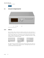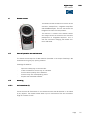
1
DigitalDigital-Player 540
User manual
manual
soulution
nature of sound
DigitalDigital-Player
User manual
540
Dear client
We are proud that you decided yourself for a soulution product. You have acquired a
product with outstanding sonic performance which you will enjoy for many years.
We understand your eagerness to get started but even though please study this
manual step by step before you integrate the Digital-Player 540 in your High Fidelity system. This manual contains also useful tips for the optimisation of your overall
HiFi-system.
If there are any questions regarding the start-up or operation of your Digital-Player
540 please do not hesitate to contact your dealer.
Have fun!
your soulution Team
Page
1
soulution
nature of sound
CECE- Declaration of Conformity
Spemot AG declares that this product is in conformance with the following directives and standards:
Low Voltage Directive 2006/95/EG (EN/IEC 60065:2002)
Electromagnetic Compatibility 2004/108/EG (EN 55013:2001, EN 55020:2002,
EN 61000-3-2:2006, EN61000-3-3:1995)
FCCFCC- Notice
Note: This equipment has been tested and found to comply with the limits for a
Class B digital device, pursuant to Part 15 of the FCC Rules. These limits are designed to provide reasonable protection against harmful interference in a residential
installation. This equipment generates, uses and can radiate radio frequency energy
and, if not installed and used in accordance with the instructions, may cause harmful interference to radio communications. However there is no guarantee that interference will not occur in a particular installation.
If this equipment does cause harmful interference to radio or television reception,
which can be determined by turning the equipment off and on, the user is encouraged to try to correct the interference by one or more of the following measures:
-
-
adjust or relocate the receiving antenna
increase the separation between the equipment and the receiver
connect the equipment into a mains outlet on a circuit different from that to
which the receiver is connected
consult the dealer or an experienced radio/TV technician for help
Disposal
According to the Directive 2002/96/EG of the European Parliament used
consumer-electro technical appliances have to be disposed separately
and have to be indicated with the following symbol.
In the case of disposal of this component please do so in conformity with legal and
environmental regulations.
Page
2
DigitalDigital-Player
User manual
540
Table of contents
1
Quick start....................................................................................................5
2
Important security advices: ............................................................................6
3
3.1
3.2
3.3
3.4
3.5
3.6
3.7
Technical Highlights......................................................................................8
Layout ..........................................................................................................8
Drive ............................................................................................................8
DSP (Digitaler Signal Processor).....................................................................8
Digital/Analog-Converter.................................................................................8
Clock and PLL (Phase Lock Loop)...................................................................9
Output stage .................................................................................................9
Power Supply................................................................................................9
4
4.1
4.2
4.3
4.4
Start of operation and handling of the Digital-Player 540 ...............................10
Scope of delivery and packing ......................................................................10
Optimal positioning of your Digital-Player 540...............................................10
Rear panel of the Digital-Player 540 .............................................................11
Front panel of the Digital-Player 540 ............................................................14
5
5.1
5.2
Programming of the Digital-Players 540........................................................20
Overview.....................................................................................................20
Program-Functions ......................................................................................21
6
6.1
6.2
Remote control ...........................................................................................27
Start of operation and maintenance ..............................................................27
Handling ....................................................................................................27
7
Protection functions of the Digital-Player 540 ...............................................31
8
8.1
8.2
Care and maintenance .................................................................................31
Burn-in.......................................................................................................31
Cleaning .....................................................................................................31
9
9.1
Trouble shooting .........................................................................................32
Actions after the appearance of an error........................................................32
10
Service .......................................................................................................33
11
Warranty.....................................................................................................33
12
Specifications .............................................................................................34
13
Dimensions.................................................................................................35
14
Individual settings.......................................................................................36
Page
3
DigitalDigital-Player
User manual
1
540
Quick start
Unpack the Digital-Player 540 and store the packing for future
transportations.
Unpacking
Security advice:
Your Digital-Player 540 has a top class
surface. Please take care during installation.
Position the Digital-Player 540 on a stable base.
Positioning
Cabling
Security advice:
Cooling air must be able to circulate and
escape unrestricted.
Disconnect all electrical appliances of your HiFi-system from
the mains supply. Connect your Digital-Player 540 with your
(pre)amplifier (according to user manual). Use the respective
signal cables and the cable for the LINK-system. Reconnect
the Digital-Player 540 and all other components of your HiFisystem with mains supply. Please use the enclosed high class
mains cable for your Digital-Player 540.
Security advice:
While manipulating with cables the Digital-Player 540 has to remain disconnected from the mains
supply.
Programming
Default values for all functions are programmed. No additional
programming is required for the start-up of your Digital-Player.
Switch-on your (pre) amplifier and turn down the volume of
your (pre)amplifier. Switch on your Digital-Player 540
Switch on
Security advice:
Before you switch on the Digital-Player
540 check whether the cabling is done correctly. Check the
volume setting in case you connected the Digital-Player 540
directly to an amplifier.
Page
5
soulution
nature of sound
2
Important security advices:
User manual:
Read this user manual carefully before you start-up the Digital-Player 540 and follow all installation and security advices.
Please keep this user manual.
Mains supply:
Exclusively use 3 phase power cords with ground conductor. They may not be
crushed by objects.
Unplug your Digital-Player 540 from the mains connection in the following cases:
-
before you manipulate with cables
before cleaning
during thunder storms or
before you leave for longer periods
Cabling:
While manipulating with cables the Digital-Player 540 has to remain disconnected
from the mains. Before you disconnect the mains the Digital-Player 540 has to be
in operating condition OFF. Wrong cabling may cause damages to your DigitalPlayer 540, your (pre)amplifier or to your loudspeakers. Excessive volumes due to
inappropriate handling may cause hearing damages.
Transport:
Use only with the cart, stand, tripod, bracket or table specified by the manufacturer
or sold with the apparatus. When a cart is used, use caution when moving
cart/apparatus combination to avoid injury or tip over.
Page
6
DigitalDigital-Player
User manual
540
Packing:
Please keep the original packing for future transports. The original packing is optimal protection against potential damages.
Operation:
Never run your Digital-Player 540
-
-
-
with opened housing
with closed cooling-slots
with high ambient temperatures (>40°C)
close to heat sources like radiators, heatings, ovens or similar appliances dissipating heat
with extremely high humidity for example in humid cellars or rooms similar
humidity
close to water (Sink, bathtub, or similar equipment)
Cleaning:
Use a soft and dry towel. We suggest using a non abrasive micro fibre towel. Please
do not use any solvents or liquidities.
Service:
Do not try to repair your Digital-Player 540 by yourself. It needs a service check by
a qualified person in the following cases:
-
the mains-cable or the mains connectors are damaged
foreign substances or liquidity has entered the Digital-Player 540
the Digital-Player 540 has seen rain
the Digital-Player 540 seems to malfunction
the Digital-Player 540 has fallen to the floor or the housing is damaged
SerialSerial- Nr.:
540 -
Please note the serial-number of your Digital-Player 540 above.
Page
7
soulution
nature of sound
3
Technical Highlights
3.1
Layout
The power supply units, the CD/SACD mechanism as well as the digital circuits are
strictly separated. The analog output section is realized in dual mono layout.
3.2
Drive
The Digital-Player 540 uses a top class mechanism of the Esoteric model range. It
allows for optimal data read-out of the CD as well as the SACD data.
3.3
DSP (Digitaler Signal Processor)
Processor)
A powerful DSP performs the calculations for the upsampling to 24Bit, 384kHz.
The DSD data of a SACD is converted into PCM format during the upsampling process. The converted data is extrapolated by a 3rd order polynomial algorithm. Additionally this DSP performs computations for the volume control and the balance settings. Thanks to the 32Bit floating comma architecture of the DSP these calculations without the usually increase of the quantification noise.
3.4
Digital/AnalogDigital/Analog - Converter
The Digital-Player 540 has one DAC board per audio channel (left/right). We use the
Burr-Brown 1792 DAC which guarantees excellent performance. Only the top quality converter section which runs up to 384 kHz of the chip is used. The internal up
sampling section is bypassed!
Two extremely fast (3MHz) I-V converters per DAC transform the output currents of
the DAC chips in voltages before they get filtered in the following stage. This ensures optimal conditions in the filter stage as well as for the I-V converters.
Page
8
DigitalDigital-Player
User manual
3.5
540
Clock and
a nd PLL (Phase Lock Loop)
Utmost precision of the clock signal is a must have for a top class D/A-Conversion.
For the synchronisation to external digital data the clock/PLL must adapt itself very
fast to eventual changes of the external data. This is done by a special digital clock
circuit that allows synchronising its clock signal very fast and at the same time extremely precise to the incoming signal.
3.6
Output stage
The output stage is optimised for velocity, precision and impulse current rating.
Thanks to its low output impedance of 10Ω and Class-A operation the output stage
is stable on every load (also long cables are driven without problems). The output
stage is a completely symmetrical design.
3.7
Power Supply
The Digital-Player 540 has two strictly separated power supply units which are
combined with a multistage filtering network for lowest mutual interferences.
The supply voltages for the analog section are stabilised in several stages for minimal deviations.
Page
9
soulution
nature of sound
4
Start of operation and handling of the DigitalDigital- Player 540
Please take care while installing the Digital-Player 540. Follow all security advices!
4.1
Scope of delivery and packing
Please check the scope of delivery:
-
Digital-Player 540
Remote Control
Mains cable
User manual
Please store the packing of the Digital-Player 540 for future transports. Check your
Digital-Player 540 for transport damages. In the case of damage, please contact
your soulution dealer.
If the Digital-Player 540 is still very cold from the
Security advice:
transport please let it warm up within the packing, in order to omit condensation of
water inside the unit.
4.2
Optimal po
p o s itioning
ition ing of your DigitalDigital-Player 540
There are no limitations on where to position your Digital-Player 540. We suggest
positioning the Digital-Player 540 so that the connecting cables to the preamplifier
remain short.
Security advice:
Please follow the security advices on page 6!
The Digital-Player 540 has a high quality surface. Please be careful while transporting so that the surface does not get scratched. Never position your Digital-Player
540 on the front panel. The display glass could get scratched or even burst
Page
10
DigitalDigital-Player
User manual
4.3
540
Rear panel of the DigitalDigital -Player 540
Rear panel of the Digital-Players 540
4.3.1
Mains (A)
Connect the Digital-Player 540 with the mains. The enclosed power cord is optimised for this application.
After switch-on of the Digital-Player 540 the standby power supply gets started. The
display shows "WAIT". Once constant conditions are reached, the Digital-Player 540
changes to operating condition OFF (red LEDs in display, power consumption <
0.5W).
Display in operating condition OFF
Security advice:
Please follow the security advices on page 6!
Only switch-off the mains connection if your Digital-Player 540 is in operating
condition OFF.
Page
11
soulution
nature of sound
4.3.2
Link (B)
The LINK-connection allows to control the switch-on of other soulution products or
to allow other soulution products to switch-on the Digital-Player 540. Connect the
LINIK-IN of the Digital-Player 540 for instance with the LINK-OUT of the Integrated
amplifier 530. Each soulution product has a LINK-OUT (Next Slave). This provides
the possibility of connecting all your soulution products. With the program-function
Start-Mode (see page 21) you can define the behaviour of the Digital-Player 540 after switch-on of the unit.
4.3.3
MainMain - Out (C)
The Digital-Player 540 has balanced and unbalanced connectors for the main output signal. Connect the output terminals with your (pre)amplifier. Due to the extraordinary load-stability of the output-stage there are no restrictions regarding the
selection of the connecting cables. We recommend using balanced cables. For short
cable lengths also unbalanced cables represent a high quality connection, top quality cable and optimal layout prerequisite.
Security advice:
Please follow the security advices on page 6!
Wrong cabling could damage your Digital-Player 540, your preamplifier, your amplifier or your loudspeakers. Excessive volumes due to inappropriate handling may
cause hearing damages.
4.3.4
Digital
Digita l - Output (D)
The Digital-Player 540 has 3 digital output connectors. (SPDIF (RCA), AES/EBU,
Toslink). Connect your favourite digital output with the digital input of your external
D/A-Converter. With the program-function
Digital-Out (chapter 5.2.9) the digital outputs can be (de)activated.
In Source-Mode CD the data from the mechanism are available at the outputs (no
signal for SCAD).
In Source-Mode DAC the digital data of the active digital input are transmitted to
the digital outputs. The data remains unchanged.
Page
12
DigitalDigital-Player
User manual
Security advice:
540
Please follow the security advices on page 6!
Wrong cabling could damage your Digital-Player 540, your preamplifier, your amplifier or your loudspeakers. Excessive volumes due to inappropriate handling may
cause hearing damages.
4.3.5
DigitalDigital -Input (E)
The Digital-Player 540 can receive external digital data from other digital sources.
The top class D/A-converter section and output-stage can thus be used for these
sources alike. It has four digital input connectors (SPDIF, AES/EBU, Toslink and
USB). The USB input can receive digital data up to 24Bit, 96kHz. The other inputs
receive digital data up until 24Bit, 192kHz.
Display für digitales Eingangssignal an SPDIF
Display bei Unterbruch des
digitalen Datenstroms
Security advice:
Please follow the security advices on page 6!
Wrong cabling could damage your Digital-Player 540, your preamplifier, your amplifier or your loudspeakers. Excessive volumes due to inappropriate handling may
cause hearing damages.
4.3.6
RS232
RS 232 Interface (F)
The Digital-Player 540 can be remote controlled through the RS232 interface. All
functions can be controlled and relevant information is provided to the control unit.
4.3.7
Type label (G)
Please note the serial number of your Digital-Player 540 on page 7 of this user
manual. This allows you to have the specific data at hand without removing your
units from the HiFi rack.
Page
13
soulution
nature of sound
4.4
Front panel of the DigitalDigital -Player 540
Front panel of the Digital-Player 540
4.4.1
Power (H)
With the Power button you define the operating condition ON or OFF (red LEDs). In
operating condition OFF the audio circuits are completely disconnected from the
output terminal (Main-Out), the mechanism and the digital sections remain deactivated. The Main-Out terminals are only activated if the Digital-Player 540 is ready
for operation and if no errors are present.
Display in operating condition OFF
Display while starting the
Digital-Player 540, StartMode NORM.
Display in operating condition ON, no disc in mechanism.
We suggest switching the Digital-Player 540 to operating condition OFF (power consumption in < 0.5W) while not listening to music. Your Digital-Player 540 can easily be activated with the remote control.
Page
14
DigitalDigital-Player
User manual
540
LINK-System:
In case the Digital-Player 540 switches on other soulution products with the LINKSystem it remains in MUTE until all connected components are switched on (Display LINK Connect).
If no errors have occurred while switching-on the other components the DigitalPlayer 540 changes into operating condition ON.
Display in operating condition OFF (Standby)
Display during switch-on of
connected units
Display in operating condition ON
When the Digital-Player 540 is switched off all connected LINK components are
switched off simultaneously (operating condition OFF).
Display during switch-off of
connected units
Display in operating condition OFF
If an error occurs within a LINK-component while operating the display shows LINK
ERROR.
Display if an error occurs
with one of the connected
units
Security advice:
Please follow the security advices on page 6!
Wrong cabling could damage your Digital-Player 540, your preamplifier, your amplifier or your loudspeakers. Excessive volumes due to inappropriate handling may
cause hearing damages.
Page
15
soulution
nature of sound
4.4.2
Open (I)
The Open button opens or closes the drawer of the Digital-Player 540. If a CD/SACD
is playing the first push on the Open button will stop the mechanism, the second
push will open the drawer. In Source-Mode DAC the mechanism can not be opened.
4.4.3
Display while opening the
mechanism.
Display while closing the
drawer of the mechanism.
Display while playing a
CD/SACD.
Security advice:
Never close the drawer by hand.
Prog (J)
The Prog button switches the Digital-Player 540 between operating-mode and programming-mode. In the programming-mode you may adjust the Digital-Player 540
to your individual requirements.
4.4.4
Select (K)
The Select knob controls the functions Track select, Volume Control, Play/Pause,
Input-Select and is used for the Programming. The behaviour of the Select knob
changes depending on the activated Source-Mode.
Page
16
DigitalDigital-Player
User manual
Source Mode: CD/SACD
SourceSource-Mode: DAC
VolumeVolume-Mode „ON“
VolumeVolume-Mode „OFF“
Track select
(4.4.4.1)
Track select
(4.4.4.1)
Play/Pause
(4.4.4.3)
Play/Pause
(4.4.4.3)
Change to VolumeControl-Mode
no function
Volume-Control
(4.4.4.4)
no function
VolumeVolume-Mode „ON“
VolumeVolume-Mode „OFF“
Input-Select
(4.4.4.2)
Input-Select
(4.4.4.2)
Change to VolumeControl-Mode
no function
Volume-Control
(4.4.4.4)
no function
Page
540
17
soulution
nature of sound
4.4.4.1
Track select
Rotating the Select knob allows selecting a new track. Rotating to the right will increase the track number, rotating to the left will decrease the track number. After 3
seconds the newly selected track will be played.
4.4.4.2
InputInput -Select
Rotating the Select knob allows selecting the digital input.
Display in D/A-ConverterMode for Input SPDIF
4.4.4.3
Display in DA-Converter
Mode for Input AES/EBU
Play/Pause
In Source-Mode CD/SACD pressing the Select knob for less than 0.5 seconds will
switch the Digital-Player 540 between Play and Pause. If the drawer is open while
pressing the Select knob for less than 0.5 seconds the drawer will be closed and the
Digital-Player 540 starts to play track 1 of the inserted CD/SACD.
Display while playing a
CD/SACD
4.4.4.4
Display for Pause
Volume Control
If the Volume-Mode has been activated, a long push on the select knob will bring
the Digital-Player 540 in Volume-Control-Mode. Rotating the select knob will
change the volume. After a timeout of approx. 3 seconds the Volume-Control-Mode
is deactivated. This ensures that the volume is changed only by purpose.
Page
18
DigitalDigital-Player
User manual
Display in Volume-ControlMode
Display after deactivating
the Volume-Control-Mode
in SACD/CD-Player Mode
540
Display after deactivating
the Volume-Control-Mode in
D/A-Converter Mode
The volume as well as the balance setting is only displayed in the Volume-ControlMode.
4.4.4.5
Programming:
Programmin g:
In programming-mode the Select knob is used for the selection of the programfunctions and the function values.
4.4.5
Display / IRIR - Receiver (L)
The display shows all relevant information for operating your Digital-Player 540.
Security advice:
The IR-receiver for the remote control is located in the
lower left corner behind the display glass. For best reception do not place any objects in front of the display.
Never place your Digital-Player 540 on the front panel. The display glass could get
scratched or even burst.
Page
19
soulution
nature of sound
5
Programming of the DigitalDigital - Players 540
5.1
Overview
The available Program-functions allow adjusting the Digital-Player 540 to your individual set-up. The Digital-Player 540 is already programmed with default settings.
Further programming is not mandatory.
Function
Func tion
Push on the Prog button switches the Digital-Player 540
between operating-mode and programming-mode. Timeout after 10 seconds.
Rotating
Rotating of the Select knob allows selecting the desired
Program-function
Push on the Select knob for approvial of the selected
function. Now the value domain of the selected function
is active. (red LEDs in display).
Rotating of the Select knob allows adjusting the desired
value.
Push on the Select knob for approval of the respective
value.
Page
20
DigitalDigital-Player
User manual
5.2
P rogramrogram- Functions
5.2.1
SourceSource - Mode
540
The Program-Function Source-Mode defines if the Digital-Player 540 works as
CD/SACD-Player or as DA-Converter.
Values:
Display for function
Source-Mode
5.2.2
CD/SACD, DAC
Default-Value: CD/SACD
Repeat
The Program-Function Repeat defines the repeat mode.
Values:
Display for function Repeat
Track, Disc, Random, OFF
Default-Value: OFF
The selected repeat mode will be shown in the display as follows.
Display for Repeat Disc
5.2.3
Display for Repeat Track
Display for Random
TimeTime - Mode
The Program-Function Time-Mode defines the time format shown in the display.
Values:
Display for function
Time-Mode
TRCK-FWD =
TRCK-BWD =
DISC-FWD =
DISC-BWD =
Default-Value: TRCK-FWD
Track time forward
Track time backward
Disc time forward
Disc time backward
Page
21
soulution
nature of sound
5.2.4
Polarity
In some cases CD/SACDs have been recorded with inverted phase. You can correct
this error with the Program-Function Phase-Polarity. Phase Polarity 180° will invert
the phase of both channels (phase shift of 180°).
Values:
Display for function
Phase-Polarity
180°
0°
= left & right inverted
= no inversion
Default-Value: 0°
Activated Phase-Polarity is shown in the display as follows
Display for activated
Phase-Polarity
5.2.5
VolumeVolume - Mode
The Digital-Player 540 has a digital volume control that can be (de)activated by the
function Volume-Mode.
Values:
Display for function
Volume-Mode
OFF, ON
Default-Value: OFF
Security advice: Make sure that the Digital-Player 540 is not connected directly to
an amplifier before you switch to Volume-Mode OFF. In Volume-Mode OFF the
maximal volume will be available at the main out terminals. Wrong handling could
damage your loudspeakers, preamplifier or amplifier.
Excessive volumes due to inappropriate handling may cause hearing damages.
Page
22
DigitalDigital-Player
User manual
5.2.6
540
StartStart- Volume
The Program-Function Start-Volume is only available in Volume-Mode ON. It defines
the volume the Digital-Player 540 play with after switch-on or the activation of the
Volume Mode. After selecting the function Start-Volume the display shows the value
domain (red LEDs active) and you may define the desired volume level.
Values:
Display for function
Start-Volume
10 - 40
Default-Value: 10
While switching to the value domain of the Program-Function Start-Volume DigitalPlayer 540 changes the current volume to the value defined in Start-Volume. Now
you are able to judge whether the Start-Volume level is appropriate. As soon as the
value domain is left the Digital-Player 540 switches back to the former volume
level.
5.2.7
MaxMax - Volume
The Program-Function Max-Volume is only available in Volume-Mode ON. You may
limit the maximal volume level in order to avoid dangerous volume levels through
malicious handling. Especially for high efficiency loudspeakers this security function should be used.
Values:
Display for function
Max-Volume
20 – 80
Default-Value: 80
While switching to the value domain of the Program-Function Max-Volume the Digital-Player 540 will not adjust the volume level for security reasons! If you limit the
volume the control range is reduced accordingly. When you reach the maximal volume level the display shows “M” (for example M 60)
Display for maximal
volume 60
Page
23
soulution
nature of sound
5.2.8
Balance
The function Balance defines the level difference between left and right channel.
You can adjust the Balance in 1 dB steps. After selecting the Program-Function
Balance the display shows the value domain (red LEDs active) and you may define
the desired volume level.
Values:
Display for function
Balance
-<- 9...0...9 ->
Default-Value: 0
While switching to the value domain of the function Balance the Digital-Player 540
changes the current volume of left or right channel according to the setting of the
Balance. Now you are able to judge whether the Balance is appropriate.
The Balance setting is only visible in the Volume-Control-Mode while changing the
volume of the Digital-Player 540.
Display in Volume-ControlMode Balance setting to
the left
5.2.9
DigitalDigital - Out
The Program-Function Digital-Out (de)activates the digital outputs
Values:
Display for function
Digital-Out
ON, OFF
Default-Value: OFF
In Source-Mode CD/SACD the data from the mechanism are available at the outputs
(no signal for SCAD).
In Source-Mode DAC the digital data of the active digital input are transmitted to
the digital outputs. The data remains unchanged.
Page
24
DigitalDigital-Player
User manual
5.2.10
540
StartStart- Mode
The function Start-Mode defines the behaviour of the Digital-Player 540 after
switch-on.
Values:
Display for Function
Start-Mode
NORM
LINK
AUTO
=> OFF (Standby)
=> depending on Link System
=> ON
Default-Value: Norm
Behaviour of the Digital-Players 540:
LINKLINKMaster
LINKLINKSlave
NORM
After switch-on of the mains the Digital-Player
540 goes to operating condition OFF (Standby).
-
LINK
LINK
After switch-on of the mains the Digital-Player
540 reacts on the incoming signal of the LINKSystem.
-
AUTO
After switch-on of the mains the Digital-Player
540 starts up automatically to ON.
-
The Power button remains active independent of the start-mode. The Digital-Player
540 can always be switched-off via the power button on the front panel.
Display for start-up of the
Digital-Player 540
Start-Mode LINK
Display for start-up of the
Digital-Player 540
Start-Mode AUTO
Display for operating
condition ON, no disc
available
Page
25
soulution
nature of sound
5.2.11
Brightness
The intensity of the display can be adjusted in three steps.
Values:
Display for function
Brightness,
1 = low
2 = medium
3 = high
Default-Value: 3
The intensity is adjusted immediately.
5.2.12
LoadLoad - Default
In the case you want to overwrite all your individual settings by the factory default
values you select the Program-Function Load-Default and you confirm with YES.
The following values will be loaded.
Display for function
Load-Default,
Security advice:
5.2.13
Source-Mode: CD/SACD
Repeat:
OFF
Time Mode: TRCK-FWD
Polarity:
OFF
Volume-Mode
OFF
Start-Volume
10
Max-Volume
Balance:
Digital-Output:
Start-Mode:
Brightness:
60
0
OFF
NORM
3
Please note your personal settings on page 36
SoftwareSoftware -Info
This function shows the version of software installed on your Digital-Player 540.
Page
26
DigitalDigital-Player
User manual
6
540
Remote control
The remote control controls all functions of the
soulution preamplifiers, integrated amplifiers
and CD/SACD-Players. You can also access the
Program-Functions of these products.
The Volume +/- buttons of the remote control
will always control the volume of the soulution
preamplifier or integrated amplifier. This is
also the case when changing the remote control to CD-mode.
6.1
Start of operation and maintenance
mainten ance
The remote control requires 2 AAA batteries (enclosed in the scope of delivery). We
recommend using only top quality products.
Exchange of batteries:
-
-
Open the battery tray on the rear side.
Insert the batteries into the tray as indicated.
Ensure correct polarity of the batteries.
Close the tray with corresponding screw.
Dispose the exhausted batteries
6.2
Handling
6.2.1
IRIR- Transmitter (1)
Ensure that the IR-Transmitter is not covered and that the IR-Receiver is not hided
by any objects. The remote control works up until a distance of 5m and a maximal
angel of incident of ±45°.
Page
27
soulution
nature of sound
6.2.2
Input ± / Next Track, (5/6)
PRE-mode:
The Input ± buttons switch between the different inputs. With
the Enter-button you change to the Record-select-mode. In this
mode the Input ± buttons allow to select the Record-IN.
CD-modus:
The Next Track buttons skip the tracks forward or backward.
In Programming-Mode (Prog-button) the Input ± buttons allow to select the desired
function and the Enter-button confirms the selection. If the value domain of a function is activated the Input ± buttons allow setting the new value and Enter-button
confirms the new setting.
6.2.3
VolumeVolume - Dim / PlayPlay -Pause (4)
6.2.4
PRE-mode:
Pressing the Volume-Dim button (de)activates the Volume Dim
function of the preamplifier or the integrated amplifier.
CD-mode:
The Play-Pause button controls the Play/Pause function of the
CD/SACD-Players
Volume ± (2, 3)
The Volume ± buttons control always the volume of the preamplifier, integrated amplifier irrespective of the PRE-/CD-mode of the remote control.
6.2.5
Page
Mute (9)
28
PRE-mode:
The Mute-button controls always the mute function of the preamplifier, integrated amplifier. The mute function disconnects
the Main-Out and the Record-Out connectors.
CD-mode:
no function
DigitalDigital-Player
User manual
6.2.6
6.2.7
6.2.8
540
Open/Close (11)
PRE-Mode:
no function.
CD-mode:
The Open/Close button controls the drawer of the player.
ProgProg - button (8)
PRE-mode:
The Prog-button switches the preamplifier, integrated amplifier
between Operating-Mode and Programming-Mode.
CD-mode:
The Prog-button switches the CD/SACD-Player between Operating-Mode and Programming-Mode.
PREPRE -button (12)
Pressing the PRE-button switches the remote control to PRE-mode for the control of
the preamplifiers or integrated amplifiers. While pressing the buttons of the remote
control the red LED (14) will light up.
6.2.9
CDCD - button (13)
Pressing the CD-button switches the remote control to CD-mode for the control of
the CD/SACD-Players. While pressing the buttons of the remote control the blue
Leds under the Play/Pause button (4) will light up.
Page
29
soulution
nature of sound
6.2.10
Power (10)
6.2.11
PRE-mode:
The Power-button defines the operating condition ON or OFF of
the preamplifier, integrated amplifier.
CD-mode:
The Power-button defines the operating condition ON or OFF of
the CD/SACD-Player.
Remote Ctrl ID
PRE-mode:
Change the transmitter Remote Ctrl ID of the remote control as
follows:
ID 1: Input+ button (6), Input- button (5) and Power (10)
ID 2: Input+ button (6), Input- button (5) and Mute (9)
Press the respective buttons for approximately 5 seconds. The
remote control confirms the new ID via red LED on its front.
The Remote Control ID of the preamplifier, integrated amplifier
has to be changed as well by selecting the Program-Function
Remote Control ID, otherwise the preamplifier, integrated amplifier will not react to the remote control no more.
CD-mode:
Page
30
The Remote Ctrl ID can not be changed.
DigitalDigital-Player
User manual
7
540
Protection functions of the Digital
Dig italital -Player 540
Comprehensive protection functions ensure a secure operation and long durability.
The Digital-Player 540 disposes over the following functions:
Overcurrent:
Overcurrent:
For currents > 0.2 Ampere at the Main-Out the preamplifier shuts down automatically.
Fuse:
The mains connection has a fuse which protects your Digital-Player 540 against too
high power consumption.
Model 220-240 V, 50-60Hz
Model 100-120 V, 50-60Hz
8
Care and maintenance
8.1
BurnBurn -in
2A/T 250V micro fuse 5x20mm
4A/T 250V micro fuse 5x20mm
The Digital-Player 540 will play on top level immediately after the first placing into
operation. However during the first 20-50 hours of operation you will notice a further improvement of its sonic qualities.
8.2
Cleaning
Please use a soft towel for the cleaning of your Digital-Player 540. We recommend
the use of a nonabrasive micro fibre towel. Please do not employ any solvents.
Security advice:
Liquidity is not allowed to enter the Digital-Player 540.
The electronic may be damaged seriously.
Page
31
soulution
nature of sound
9
Trouble shooting
Error
Action
No display
Check the cabling to the mains supply. Eventually replace
the fuse of the Digital-Player 540.
No music
9.1
Check the cabling to your (pre)amplifier, eventually from
the preamplifier to the amplifier and from the amplifier to
the loudspeakers, whether the preamplifier is switched on
and you have selected the correct input, whether the
power amplifier is switched on.
POWER FAIL
If the power supply to the audio channels is interrupted or
an error in the power supply unit has occurred the DigitalPlayer 540 is shut down automatically. The display shows
POWER FAIL.
OVERCURRENT
If the current at the Main-Out exceeds 0.2 ampere the
Digital-Player 540 is shut down automatically. The display
shows OVERCURRENT.
Actions after the appearance of an error
If you con not identify the error please disconnect the mains supply (before you disconnect the Digital-Player 540 has to be in operating condition OFF) and contact
your soulution dealer.
Page
32
DigitalDigital-Player
User manual
10
540
Service
If your soulution Digital-Player 540 needs service please contact your soulution
dealer. For further information see www.soulution-audio.com
11
Warranty
All soulution products are guaranteed against defects in material and workmanship
for five years from date of purchase.
The guarantee is void if the Digital-Player 540 has been subject to misuse or negligence or has been modified, repaired or opened by a non authorised person without
written authorisation of Spemot AG.
For the return transport to our premises please use exclusively the original packaging. Transport damages are not subject to this guarantee, repairs will be charged.
We recommend effecting transport insurance.
If you do not posses the original packaging no more please contact your soulution
dealer.
Basic repairs may be completed by your soulution dealer. Please clarify whether he
is able to do the work before you send the Digital-Player 540 back to us.
Page
33
soulution
nature of sound
12
Specification
Specific ations
ation s
Specifications
Specificatio ns
Data
Nominal voltage
Model 220 – 240 V / 50 – 60 Hz
Model 100 – 120 V / 50 - 60 Hz
Power consumption
OFF (standby)
ON
MainMain - Out
Output voltage
Peak Output Current
Impedance
Frequency response
Distortion (THD)
Signal to Noise Ratio
Volume range
Balance range
DigitalDigital - Out
Output-Voltage
Output-Impedance
DigitalDigital -In
Sensitivity
Input-Impedance
PLL – control range
LINKLINK-System
Page
34
220 – 240 V
100 – 120 V
<0.5 W
50 W
balanced
unbalanced
Main-Out symmetrical
Main-Out asymmetrical
(depending on data format)
4
2
1
10
10
DC-100
<0.0002
140
0…-80
<- 9...0...9 ->
S/PDIF
AES EBU
S/PDIF
AES EBU
500
5
75
110
S/PDIF
AES EBU
0.3 - 5
75
110
+/- 100
Vrms
Vrms
A
Ω
Ω
kHz
%
dB
dB
dB
mV p-p
V p-p
Ω
Ω
V p-p
Ω
Ω
ppm
+12 V
DigitalDigital-Player
User manual
13
540
Dimensions
Dimension s
Page
35
soulution
nature of sound
14
Individual
Individu al settings
Function
Func tion
Source-Mode
Repeat
Time-Mode
Polarity
36
DefaultDefault- Value
CD/SACD
OFF
TRCK FWD
0°
Volume-Mode
OFF
Start-Volume
10
Max-Volume
60
Balance
Page
Setting
0
Digital-Out
OFF
Start-Mode
NORM
Brightness
3
Spemot AG
Industriestrasse 70
CH-4657 Dulliken
www.soulution-audio.com
[email protected]
soulution
nature of sound
part.no. 92142