1
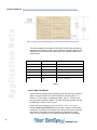
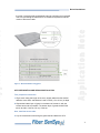
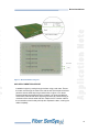
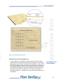
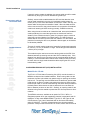
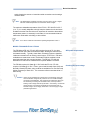
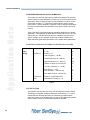
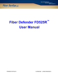
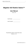
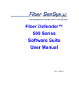
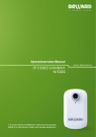
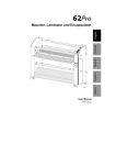
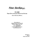
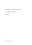
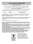
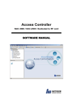
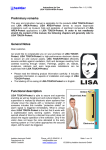
SUMMARY
The versatility of fiber optic intrusion detection
technology promotes effective use in a wide variety of
sensor platforms. Deployed as a buried sensor, the
completely inert sensor cable offers benefits unmatched
by any other sensor technology. A correctly designed and
installed buried fiber optic sensor system can provide a
highly reliable intrusion detection system with a very long
service life. However, the nature of fiber optic sensing
means that there are limitations on how and where the
method can be used. This application note defines the
appropriate applications for buried fiber optic sensing,
and details the design, installation and calibration process
that will ensure a reliable detection system.
Application Note
INTRODUCTION
The planning stage is the first step to a successful buried
installation. Planning includes a comprehensive site survey
as well as good system design. The second step is the
actual equipment installation. Equipment installation involves
the alarm processor and sensor cable installation. The third
step to a successful deployment is system testing and
maintenance. System testing is performed after equipment
installation in order to tune the system and ensure optimal
performance. Maintenance involves periodic system checks
that ensure reliability and long life of the sensor deployment.
Buried Installations
The ideal deployment medium for a buried fiber optic sensor
zone is a bed of round river gravel. In some applications, the
fiber optic sensor cable may also be placed in sand or under
sod and landscaping materials. SC-4 fiber optic cable is well
suited for direct burial and has a twenty year life expectancy.
The Fiber Defender FD-300 series and FD-208 Alarm
Processing Units may be used for buried applications. SC-4
sensor cable, with its rugged jacketing, is rated for direct
burial and should be used in all buried installations. SC-4
sensor cable is UV resistant and flame retardant.
To correctly monitor the optical signal in a buried fiber optic
sensor cable, the Alarm Processing Unit (APU) is configured
differently than for use in fence applications. APUs must be
configured at Fiber SenSys for use with buried sensor cable.
Therefore, it is necessary when ordering FD-208 or FD-300
series APUs to specify that they will be used with buried
sensor cable. The FD-220P APU is not available in buried
sensor configuration, and is not approved for use with buried
sensor cable.
AN-SM-001
Rev. C 02/09
Buried Installations
Application Note
Although the fiber optic sensor cable may be deployed in a number of ways,
there are limits to the capabilities of both the sensor cable and the APU. The
most ideal medium for buried sensor cable is a well-drained gravel bed in a
snow-free environment. Land, sand and other soil deployments can also be
effective, provided the soil does not harden or freeze. The use of buried fiber
optic sensor cable is not recommended for use in:
2
• Hard-packed earth of any kind, or bare ground without a layer of yielding
ground cover such as grass
• Dry, compactible sod
• Ground subject to freezing
• Ground subject to accumulations of snow exceeding 3 - 4 inches (7 - 10
cm), depending on the type of ground and snow, unless the snow can be
kept clear of the sensing zone
• Concrete or asphalt
When working with Fiber SenSys’® fiber optic sensor, there are two
important characteristics to remember:
1. The cable senses motion and vibration. In a buried application,
vibration and tiny motions due to flexing the fiber are the primary modes of
stimuli. When the sensor cable is buried in sand or soft soils, vibration is
rapidly dampened and thus negligible. In this case, microscopic movement
of the fiber under ground pressure becomes the primary mode of sensor
stimulation. In any ground medium that does not couple either vibration or
ground motion to the sensor cable, the buried fiber optic cable will not
operate reliably.
2. Sensor cable placement and spacing is defined by the medium. If the
sensor is buried in a material that couples vibration to the cable, such as a
bed of round gravel, the cable strands can be spaced between 12 and 16
inches (30 - 40 cm) apart. In ground that does not couple vibration, such as
sand or sod, the primary sensing mode is slight bends in the fiber
introduced by pressure on the ground above. For these applications,
sensor cable must be spaced more closely together, between 6 and 12
inches (15 - 30 cm).
PLANNING
The first step to a successful buried installation, as with any perimeter
application, is performing a comprehensive site survey. The site survey
encompasses a threat assessment, a site drawing and a site walk-through.
Analysis of the data obtained through this process will aid in the proper
planning of zone layout, sensor and equipment selection and equipment
quantities.
THREAT ASSESMENT
The threat assessment is usually simple for an older, established site since
the site may have a history of break-in types. Threat assessment for a new
facility requires careful consideration of the facility and possible intrusion
methods. Slow walking intrusion, running, crawling and tunneling may be
typical threats at any given site. Other types of trespasses are also
important to consider at this stage. The threat assessment must take into
consideration and answer several key questions:
1. Given the nature of the facility, what is the maximum level of experience
and knowledge of expected intruders? For basic commercial facilities, the
primary threat is theft and vandalism by untrained intruders, but for highvalue or strategic sites, intrusion attempts by experienced intruders with
knowledge of security systems may be expected and must be planned for.
2. What are the most likely entrance points on the perimeter?
3. Does the perimeter contain vulnerabilities that can be used to facilitate
undetected entry into the premises?
Examples:
a. Trees that permit sensor areas to be bypassed or “bridged”
b. Culverts or tunnels
c. Areas difficult to sensor, such as streams, heavy vegetation
or irregular ground
d. Hard-surfaced roads and walkways
The presence of small animals and other ground-related disturbances must
also be taken into account. For example, a guard dog kept inside a
compound may cause alarms if it has access to the ground containing the
sensor cable. Similarly, a raccoon or cat leaping from the top of a fence
may cause an alarm as it hits the gravel and bounces in a leaping second
step. Loose debris or tree limbs hitting the ground over the sensor during a
wind storm may cause nuisance alarms. Steps must be taken to reduce the
potential for such nuisance alarms. For example, overhanging trees or
limbs may be removed, perimeter fencing with outriggers may be used to
reduce animal trespass and guard dog travel may be restricted.
A detailed site drawing showing building and perimeter layout and lengths
should be obtained. A site walk-through using the site drawing should be
conducted. During the walk-through, take notes that reflect any details not
contained in the drawing such as hills, dips and other topography issues.
Also note any objects that would facilitate intruder bypass of the intrusion
detection system, such as trees or other vaulting aids. Analysis of the data
obtained during the threat assessment and the site evaluation will be used
to determine zone layout, intrusion detection model type and equipment
quantities.
Reducing prospective
nuisances
Application Note
Application Note
Buried Installations
3
Buried Installations
ALARM DEVICE AND MONITORING PLAN
Application Note
Alarm relay output uses
Installation site
considerations
Cable handling precautions
Next, the selection of the alarm device and monitoring procedure should be
conducted. For example, the threat of trespass into a fenced area may be
countered by a sensor buried in gravel inside the fence; the alarm
mechanism may be a loud bell or activation of flood lights and monitoring
may be made by a local patrol service notified by an auto-dialer attached to
the alarm output. Alternatively, the alarm relay output may be used to
trigger video assessment.
SENSOR CABLE INSTALLATION
All buried installations should use SC-4 sensor cable, rated for direct burial.
All buried installations should also use vinyl flexible construction mesh,
commonly used at construction sites (such as Nordic II Polyethylene
mesh), to keep the sensor cable in place. Use zip ties to attach the SC-4
sensor cable loosely to the construction mesh.
If the fiber optic sensor cable is deployed in gravel within 6 inches of a
fence, it may detect vibration transmitted to the surrounding ground
through the fence posts. This may allow vibration from wind gusts on the
fence to transmit through the ground to the buried cable.
Therefore, it is recommended the cable be deployed further away from the
fence or the Level of Signal in the APU raised until such a disturbance is
no longer detected.
For similar reasons, the softness or hardness of the soil in a lawn
installation is also extremely critical. Soft soil conditions (frequent watering
is ideal) provide the best medium for detection without excessively coupling
vibration from vehicle traffic.
Take into consideration the potential condition of the site during the
different seasons of the year. Accumulation of snow over the buried zone
may dampen vibration or ground movement, which can reduce the
sensitivity of the system. When ground can freeze, it can completely
dampen the ground’s response to disturbance, so the use of a buried fiber
optic sensor is not recommended in ground subject to strong freezing.
When installing optical fiber, the general characteristics of the fiber should
be understood. In addition, there are several safety precautions that should
be followed to avoid cable damage or personnel injury:
• Do not pull the cable by the connectors
• Maximum cable pulling tension of 60 lbs should not be exceeded at any
time
• The cable should be pulled in a steady, continuous motion only
• Do not push the cable at any time
4
• Do not bend the cable in a radius tighter than 2 inches (5 cm)
• Do not twist the cable - spiral fracturing may develop
• Keep the connectors capped until they are used
• Clean connectors prior to coupling to mating connectors
The following precautions should be observed to maintain a safe work
environment:
• Wear safety glasses and gloves when cutting and stripping cable
• Cut pieces of fiber should be disposed of immediately in a closeable
container labeled “Scrap Fiber” - small pieces of cut fiber can damage
the eye or pierce the skin
• Use caution when cleaning the fiber. Some solutions used to clean
optical fibers can cause skin and eye irritation and respiratory
problems.
SENSOR CABLE LAYOUT
Depending on the medium in which the sensor cable is buried, a single
strand of buried cable can detect someone walking or crawling on the
surface for only a short distance to either side. When buried in gravel, a
single strand can detect approximately a 12 inch (30 cm) area, while in
sod or sand the width of the sensing area may be as small as 6 inches
(15 cm). In either case, this is not wide enough to ensure detection of an
intruder. To widen the area of sensing coverage, SC-4 sensing cable is
deployed back and forth along the length of the buried sensor zone in a
pattern of serpentine loops. Correctly spaced loops across the desired
width of the buried zone will ensure continuous sensing coverage.
Below is illustrated a sample deployment of buried sensing cable in a
bed of gravel for a high-security detection zone. The sensing cable is
deployed in three serpentine loops (six strands of cable) with the strands
spaced about 12 inches (30 cm) apart. This provides a very high level of
detection for a sensing zone about 6 feet (180 cm) in width.
To increase the width of the sensing zone, simply add additional loops of
sensor cable until the desired width is achieved.
Application Note
Application Note
Buried Installations
5
Application Note
Buried Installations
Figure 1 – High security sample deployment – buried sensing cable in a bed of gravel.
The spacing between the strands of buried SC-4 cable varies according to
the type of burial medium and the level of detection capability desired. The
table below shows recommended fiber spacing for different materials and
security levels.
When buried in
Security Level
Cable Spacing
Gravel
Medium
16” (40 cm)
Gravel
High
12” (30 cm)
Sod
Medium
10 - 12” (25 - 30 cm)
Sod
High
6 - 8” (15 - 20 cm)
Sand
Medium
10 - 12” (25 - 30 cm)
Sand
High
6 - 8” (15 - 20 cm)
Table 1
DEPLOYMENT IN GRAVEL
Figure 2 shows a typical layout for deploying the fiber optic sensor cable in
gravel. Using this medium, the cable is placed on a bed of gravel 3 - 6
inches (8 - 15 cm) deep in a serpentine pattern, with 12 - 16 inches (30 40 cm) of spacing between passes. The cable should be covered over with
an additional 3 inches (8 cm) of gravel.
Round “pea” gravel ranging in size from 3/4” to 1-1/2” (2 - 4.8 cm) in
diameter Gravel specifications should be used in order to provide good
conductivity of pressure and vibration over a large surface area. Using this
size of gravel, the cable can sense footsteps at a distance of several
inches. Do not use gravel or rock with sharp edges as this may damage
6
the cable. Crushed gravel should not be used as it will become compacted
over time, preventing the transmission of vibration and pressure-induced
motion to the sensor cable.
Figure 2 – Buried installation using gravel.
SITE PREPARATION AND SENSOR INSTALLATION
First, prepare the buried zone:
1. Dig a trench along the length of the zone, slightly wider than the desired
detection zone width, and between 6 and 9 inches ( 15 to 23 cm) in depth
Application Note
Application Note
Buried Installations
2. Deposit the bottom layer of gravel in the bottom of the trench, with the
surface as smooth as possible. The bottom layer of gravel should fill the
trench to within 3 inches (7.6 cm) of the top
Next, install the sensor cable:
3. Lay the construction mesh along the gravel bed and attach the SC-4
7
Buried Installations
Application Note
sensor cable to the mesh with zip ties. Deploy the sensor cable back and
forth along the length of the zone in a serpentine pattern. Depending on
the level of detection capability desired, the cable strands should be
spaced 12 - 16” (30 - 40 cm) apart
Sand/dirt accumulation
Preventing freezing
4. Install C-300 or equivalent connectors on the ends of the sensing cable.
Be sure to leave enough cable to allow connection to the APU, or to
insensitive cable leading to a remote APU
5. Connect the ends of the sensing cable to an Alarm Processing Unit to
make sure the cable has not been damaged during the installation process.
With the APU powered, ensure that the “FAULT” LED is not illuminated.
Also, check the APU’s “STATUS” function to ensure that the cable loss is
less than 10 dB. Refer to the section on APU calibration and maintenance
and to the APU user’s reference manual for testing procedures
Finally, finish the gravel bed:
6. Lay the top layer of gravel, 3 inches (7.6 cm) thick, across the length of the
zone. Again, smooth the gravel bed as much as possible
7. With the sensing cable connected to the APU, again test the cable for
continuity, and test the system for performance. Adjust the APU’s
parameters as needed for desired detection performance
8. If the sensing cable is connected to insensitive cable using feed-through
connectors, install one ENKT-661 Encapsulator Kit over each optical
connector. The clam-shell type encapsulator is filled with sealing gel and
when closed provides a waterproof seal for the connectors device.
In regions where there are no snow or freezing conditions, the major
concern is how much sand or dirt will accumulate in the gravel. This
accumulation will dampen the transmission of pressure and vibration
through the gravel. If these conditions exist, the space between sensor
cable strands should be no more than 12 inches (30 cm).
In regions with severe freezing conditions, the gravel bed must have good
drainage. When water freezes, trapping the gravel, very little vibration will
be coupled to the sensor. For a similar reason, snow will also desensitize
the system,. When accumulation of snow reaches 3 - 4 inches (7 - 10 cm),
the snow must be removed in order for the system to detect human
trespass.
SOD
Figure 3 shows a typical deployment for using fiber optic sensor cable
under sod or grass. The sensor cable can be placed directly beneath the
sod or landscaping materials.
8
Figure 3 – Buried installation using sod.
SOD DEPLOYMENT PROCEDURE
Installation begins by cutting through the lawn using a sod cutter. Ensure
the cutter cuts through the roots of the sod as well. Roll the lawn back and
place the sensor cable atop the ground as show in figure 3. For those
instances where large areas are being covered, it is recommended that
construction mesh be laid down atop the ground first to prevent shifting or
movement of the sensor cable with time. Attach the SC-4 sensor cable to
the construction mesh loosely with zip ties. Replace the lawn, covering the
cable completely.
Application Note
Application Note
Buried Installations
9
Buried Installations
Application Note
Sod deployment
requirements
Sand installation
guidelines
10
When the sensor cable is buried under a lawn, very little motion or
pressure is transmitted to it. Intruders must step directly over the cable in
order to be detected. To ensure detection of a lightweight human, the lawn
must be kept moist to transmit sufficient energy to the sensor cable
(requiring frequent watering). Placing the cable directly onto hard clay is
not recommended because of the clay’s inability to couple pressure and
vibration to the sensor. For those instances where deploying the sensor
cable atop hard clay is unavoidable, a layer of sand should be placed
directly under the sod, providing enough of a cushion to allow pressure to
disturb the sensor.
Typically, a minimum 6 - pass deployment is used in a sod installation.
This will provide up to about 6 feet (1.8 meters) of detection zone width. As
with gravel-based deployments, the sensor cable is invisible to the intruder
when deployed in this manner. It is important with this configuration that
the intruder be unaware of the exact location of the sensor cable since it
may be possible for an intruder to leap over a 6 - 8 foot (1.8 - 2.4 m) span
without being detected. To fully eliminate this vulnerability, additional loops
of sensor cable can be used for a wider detection area.
SAND
Figure 4 shows a typical deployment for burying fiber optic sensor cable
under sand. The SC-4 sensor cable should be attached to the construction
mesh and buried beneath 4 inches (10 cm) of sand in a serpentine pattern,
with 6 -12 inches (15 - 30 cm) of spacing between each pass. The
construction mesh is used to stabilize the sand and maintain cable depth.
Typically, a minimum 6 - pass deployment is used in a sand installation,
providing up to 6 feet (1.8 m) of detection. Additional loops can be used to
increase the zone width. As when using buried cable with gravel or sod, it
is important that the intruder remain unaware of the exact location of the
sensor cable.
Figure 4 – Buried installation using sand.
MAKING SENSOR CABLE INSENSITIVE
In some instances, it is desirable to render portions of the sensor cable
insensitive when it is buried below a driveway or walkway. This is done by
deploying the sensor cable in hardened conduit beneath the surface of the
driveway or walkway to a depth of at least 12 inches (30 cm). Generally, at
such a depth, pedestrians will not cause enough energy to be transmitted
to the cable (unless gravel is used for the walkway). If the system is to be
active when the driveway or walkway is in use, it may be necessary to
increase the depth to 2 - 3 feet (60 - 90 cm) to avoid nuisance alarms from
vehicle traffic.
Application Note
Application Note
Buried Installations
Routing sensor cable
beneath walkways
11
Buried Installations
If gravel is used to create the walkway, the sensor cable can still be made
insensitive by burying it in the soil beneath the gravel layer.
Application Note
Using sensor cable as
insensitive leads
Conduit diameter
Similarly, sensor cable routed between the APU and the detection zone
can be made insensitive by burying it in hardened conduit at least 12
inches (30 cm) in the soil of the exterior environment. Used in this way, the
sensor cable can be used as insensitive “leads”. When the leads exit the
soil en route to the APU, they should remain in the protection of hardened
conduit until entering the APU housing (normally, a NEMA enclosure).
When using the sensor cable as an insensitive lead, ensure the hardened
conduit protecting it is routed through and to an area that is free from
vibration (if the conduit is buried in gravel, for instance, keep in mind that
gravel may conduct vibration from nearby traffic). The APU enclosure
should also be mounted in an area free from vibration. For this reason, the
practice of mounting the APU on a pedestal is discouraged, as wind tends
to vibrate the pedestal.
The type of conduit used to protect the “insensitive” leads should generally
be 1/2 inch (1.27 cm) in diameter or larger. Elbow fittings should measure
3 inches (8 cm) or larger.
This method may be used to connect the sensing cable to the APU if the
distance between the sensing zone and the APU is relatively short. If the
distance from the APU to the sensing zone is more than about 33 feet (10
meters), it is recommended that a remote APU model (FD-208 or FD-34x)
be used, with true single mode insensitive cable coupling the APU to the
buried sensing cable.
ALARM PROCESSING UNIT (APU) INSTALLATION
Model FD-331 / FD-332
The FD-331 / FD-332 Alarm Processing Unit (APU) must be housed in a
NEMA 4 enclosure when installed outdoors. When routing cable into the
enclosure, the fiber optic cables may pass through an opening as small as
half an inch. The opening must be sealed once the electrical / optical cable
is fed through so that no moisture may enter the enclosure. When routing
the fiber optic cable, it must be routed through the strain reliefs provided on
the back plate of the enclosure so that no stress will occur at either the
laser or detector junctions on the APU. Similarly, an opening made for the
electrical wiring must be sealed to protect the APU from exposure to dirt or
moisture.
The NEMA 4 enclosure, available as an option for FS LLC APUs, is
fiberglass polyester which has outstanding chemical, temperature and UV
resistance. It also meets NEMA-EEMAC Type 4X, UL 508 Type 4X and
CSA Enclosure Type 4 and 5 standards with an enclosure flammability
rating of UL945-5V. The quick release latches have knockout padlock
provisions. Always mount the enclosure on a solid, motion-free structure to
12
avoid vibrating the sensor or insensitive cable connections and creating a
nuisance alarm.
Note: The temperature inside the enclosure may be as much as 20° F higher
than the outside temperature as measured in direct sunlight.
The maximum allowable temperature of the FD-331 / FD-332 APU is 55° C
(131° F). It is usually adequate to simply keep the electronics unit enclosure
shaded so that the heat from direct sun exposure will not add to the ambient
temperature present. In extremely hot climates, it is recommended that the
electronics reside within a building or other shelter.
Note: SC-4 sensor cable has a maximum operating temperature of 85° C.
MODEL FD-208 AND FD-341 / FD-342
Application Note
Application Note
Buried Installations
The FD-208 and FD-341 / FD-342 APUs require the use of IC-4 or other
insensitive fiber optic cable as insensitive leads, allowing the electronics to
be located remotely. Typically, these Alarm Processing Units are installed
inside secure areas such as security control rooms. The FD-341 / FD-342 is
available as a stand-alone model. The Model FD-208 is available in both
stand-alone and the rack-mounted versions. The FD-341 / FD-342 and
standalone FD-208 can be ordered with an optional NEMA 4 enclosure.
APU power requirements
The FD-208 requires 2.2 Watts @ 12 VDC while the FD-341 / FD-342
requires 3.0 Watts @ 12 VDC. Power, ground and Normally-Open (NO) and
Normally-Closed (NC) alarm relay contacts are available on a connector strip
(Molex connector) of each APU. This connector will accommodate 28 to 14
AWG wiring.
Checking DC input voltage
Caution! There can be significant DC voltage drop in small gauge wiring. Be
sure that the DC voltage at the processor is over 10 VDC following
connection and installation. The voltage in the stand-alone APU can
be checked by accessing the “STATUS” menu, which provides a
reading of the voltage received by the APU. If necessary, use heavier
gauge wiring for long exterior perimeter DC supply leads and / or
consider using a 24 volt supply rather than a 12 volt supply in larger
perimeter applications.
13
Buried Installations
Application Note
ALARM PROCESSING UNIT (APU) CALIBRATION
The signals from the fiber optic sensing cable when deployed for a buried
sensor system are quite different from those from a fence-mounted sensor,
especially in terms of signal strength and the distribution of power across
the acoustic frequency. To achieve the desired level of sensor system
performance, it will be necessary to adjust the APU’s detection parameters
to match the performance characteristics of the sensor cable in the burial
medium.
Table 2 lists the recommended starting calibration settings for any buried
application. These settings are applicable to the FD-208, FD-331 / FD-332
and the FD-341 / FD-342 alarm processors. Ultimately, type and size of
gravel, condition of soil, moisture content and variation of deployment
depth and spacing will affect optimization of the system alarm parameters.
STARTING CALIBRATION SETTINGS FOR BURIED APPLICATIONS
Password
Gain
Setup
menu
Processor 1
Processor 2
Wind
Parameter
Setting
(1 - 50)
26
Enable (Y or N)
Level of Signal (1 - 40 dB)
Y
8
Lowest Frequency (10 - 600 Hz)
10
Highest Frequency (10 - 600 Hz)
Duration of Signal (1 to 25 sec/10)
150
10
Low Level Tolerance (1 - 10 dB)
2
Event Count (1 - 100)
Event Window (1 - 200 sec/10)
2
50
Event Mask Time (0 - 100 sec/10)
1
Enable (Y or N) Enable Wind
Dependent Processing (Y or N)
N
N
Table 2
SYSTEM TESTING
The objective of these tests is to verify that all subsystems were installed
according to acceptable installation standards and practices, (i.e., proper
mechanical and electrical fabrication and assembly procedures were
used), the system is connected properly to each of the related subsystems
and the system meets or exceeds the acceptance standard.
14
In terms of acceptable standard, criteria used to define whether a zone
setup is acceptable or not include:
• Simulated intrusion attempts are detected to the required Probability of
Detection (PD)
• All intrusion and tamper alarms must be properly detected and displayed
Testing consists of tamper tests, line fault tests and intrusion tests. The
order in which these tests are performed is left to the discretion of the test
director. If the Intrusion Detection System (IDS) configuration includes a
redundant annunciator, these test procedures shall be interpreted to
include both annunciators.
TAMPER TEST
Note: Applies only to APUs mounted in enclosures equipped with
tamper-detect switches.
The Tamper Test verifies the proper performance of the tamper switch in
each NEMA enclosure.
1. Confirm that all alarm lights and audible alarms on the annunciator
equipment are reset
2. Proceed to the first NEMA enclosure to be tested. Open the door and
verify that the correct alarm is displayed at the annunciator equipment
and observe the tamper alarm at the annunciator
3. Record the results on the FS LLC Test and Acceptance Log
4. Secure the NEMA enclosure door
5. Reset the annunciator
6. Repeat steps 1 - 5 for all remaining NEMA enclosures to be tested
The Test and Acceptance Log can be found in Chapter 5 of each of the APU
User’s Reference Manuals.
FAULT TEST
Application Note
Application Note
Buried Installations
This test will verify that a loss of signal continuity in the optical circuit is
properly reported to the annunciator equipment.
1. Disconnect the fiber optic cable from the “Output” connector of each
available channel on the APU
2. Verify that the red “FAULT” LED is illuminated on the APU
3. Verify that a FAULT alarm is generated on the annunciator equipment
15
Buried Installations
4. Record the test results in the FS LLC Test and Acceptance Log
5. Reconnect the cable
6. Verify that the red “FAULT” LED extinguishes
Application Note
7. Repeat steps 1 through 6 for each APU to be tested
16
Note:
The Test and Acceptance Log can be found in Chapter 5 of each of the
APU User’s Reference Manuals.
INTRUSION DETECTION WALK TEST
The Intrusion Detection Walk Test determines the Probability of Detection
(PD) for an intruder attempting to walk across the detection zone.
1. Have an individual walk across the detection zone in a crouch (“duck
walk”), at approximately 1 step per second
2. Verify that an alarm is generated at the annunciator equipment
3. Record the test results in the FS LLC Test and Acceptance Log
4. Reset the annunciator equipment
5. Repeat steps 1 through 4 a minimum of 20 times for each detection
zone
6. Determine the probability of detection (PD) by dividing the number of
alarms generated by the number of attempts (e.g. 19 alarms generated
out of 20 attempts). Multiply this number by 100 to receive the PD
(19/20 = .95 x 100 = 95%)
7. Record this number in the Test and Acceptance Log
8. Repeat steps 1 through 7 for each APU to be tested
Note:
If the PD is too low, adjust the APU Gain or Processor 1 Level of Signal,
Event Window and Event Count settings to achieve an acceptable PD. Refer
to the respective APU user’s manual for procedures on adjusting variables.
INTRUSION DETECTION RUN AND JUMP TEST
This test will determine the Probability of Detection (PD) for an intruder
attempting to run and jump across the detection zone.
1. Confirm that all alarm lights and audible alarms on the annunciator
equipment are reset
2. Have an individual take up a position approximately 7.5 meters (25 ft)
from the detection zone, so as to permit a good running jump across the
detection zone as high as possible. The follow-through run should
continue approximately 7.5 meters (25 ft) beyond the cable to complete
the run and jump test
3. Verify that an alarm is generated at the annunciator equipment
4. Record the results on the FS LLC Test and Acceptance Log
5. Reset the annunciator equipment
6. Repeat steps 1 -5 a minimum of 20 times for each detection zone
7. Determine the probability of detection (PD) by dividing the number of
alarms generated by the number of attempts (e.g. 19 alarms generated
out of 20 attempts). Multiply this number by 100 to receive the PD (19/20
= .95 x 100 = 95%)
8. Record this number in the Test and Acceptance Log
9. Repeat steps 1 through 8 for each APU
Note:
If the PD is too low, adjust the APU Gain or Processor 1 Level of Signal,
Event Window and Event Count settings to achieve an acceptable PD.
MAINTENANCE
Although the Fiber Defender series processors require little
maintenance, in order to ensure a long lasting and reliable deployment,
there are some preventative maintenance items that should be
conducted periodically. Maintenance of the system involves checking
system parameters, checking the integrity of the deployed sensor cable
and periodic system response testing. These maintenance items should
be conducted quarterly.
Using a Hyperion Hand held Calibrator or a laptop running SpectraView
or terminal emulation software, connect to the alarm processor through
the RS-232 port on the APU. Check the “STATUS” of the APU to
determine the overall health of the system. Compare the values
displayed against the values recorded during system installation and
calibration. Any change from the previously recorded values should be
evaluated.
®
Application Note
Application Note
Buried Installations
17
Buried Installations
Application Note
A walk through of the detection zones should be conducted periodically
to check the performance of the system and the physical integrity of the
sensor cable. In addition to confirming the detection capability of each
zone, look for any signs of digging that may indicate damage to the
cable. Check the cable where it exits the ground, its length between the
ground and the alarm enclosure and the connections to the APU for
physical integrity.
For more information on using the Fiber Defender series products with a
buried application, please contact Fiber SenSys’® technical support team
directly at +1-503-692-4430 or by email at [email protected].
2925 NW Aloclek Drive, Suite 130
Hillsboro, OR USA 97124
Phone: +1-503-692-4430
Fax: +1-503-692-4410
www.fibersensys.com
© Copyright 2009 Fiber SenSys™. Printed in the United States of America. All Rights Reserved Worldwide. No part of this publication may be copied
or distributed, transmitted, stored in a retrieval system, or translated in any form or by any means, electronic, mechanical, magnetic, manual, or
otherwise, without the express written permission of Fiber SenSys, 2925 NW Aloclek Drive, Suite 130, Hillsboro, Oregon USA 97124.
18