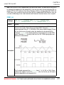
1
mikroC PRO for AVR
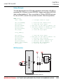
Develop your applications quickly and easily with the world's
most intuitive mikroC PRO for AVR Microcontrollers.
Highly sophisticated IDE provides the power you need with
the simplicity of a Windows based point-and-click
environment.
With useful implemented tools, many practical code
examples, broad set of built-in routines, and a
comprehensive Help, mikroC PRO for AVR makes a fast and
reliable tool, which can satisfy needs of experienced
engineers and beginners alike.
mikroC PRO for AVR
December 2008.
Reader’s note
DISCLAIMER:
mikroC PRO for AVR and this manual are owned by mikroElektronika and are protected
Reader’s Note
by copyright law and international copyright treaty. Therefore, you should treat this manual
like any other copyrighted material (e.g., a book). The manual and the compiler may not be
copied, partially or as a whole without the written consent from the mikroEelktronika. The
PDF-edition of the manual can be printed for private or local use, but not for distribution.
Modifying the manual or the compiler is strictly prohibited.
HIGH RISK ACTIVITIES:
The mikroC PRO for AVR compiler is not fault-tolerant and is not designed, manufactured
or intended for use or resale as on-line control equipment in hazardous environments requiring fail-safe performance, such as in the operation of nuclear facilities, aircraft navigation or
communication systems, air traffic control, direct life support machines, or weapons systems,
in which the failure of the Software could lead directly to death, personal injury, or severe
physical or environmental damage ("High Risk Activities"). mikroElektronika and its suppliers
specifically disclaim any express or implied warranty of fitness for High Risk Activities.
LICENSE AGREEMENT:
By using the mikroC PRO for AVR compiler, you agree to the terms of this agreement.
Only one person may use licensed version of mikroC PRO for AVR compiler at a time.
Copyright © mikroElektronika 2003 - 2008.
This manual covers mikroC PRO for AVR version 1.23 and the related topics. Newer versions may contain changes without prior notice.
COMPILER BUG REPORTS:
The compiler has been carefully tested and debugged. It is, however, not possible to
guarantee a 100 % error free product. If you would like to report a bug, please contact us at
the address [email protected]. Please include next information in your bug report:
- Your operating system
- Version of mikroC PRO for AVR
- Code sample
- Description of a bug
CONTACT US:
mikroElektronika
Voice: + 381 (11) 36 28 830
Fax:
+ 381 (11) 36 28 831
Web:
www.mikroe.com
E-mail: [email protected]
Windows is a Registered trademark of Microsoft Corp. All other trade and/or services marks
are the property of the respective owners.
MIKROELEKTRONIKA - SOFTWARE AND HARDWARE SOLUTIONS FOR EMBEDDED WORLD
USER MANUAL
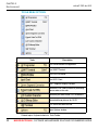
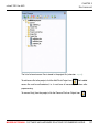
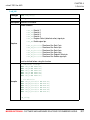
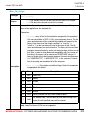
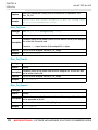
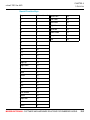
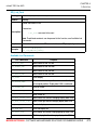
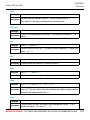
Table of Contents
CHAPTER 1
Introduction
CHAPTER 2
mikroC PRO for AVR Environment
CHAPTER 3
mikroC PRO for AVR Specifics
CHAPTER 4
AVR Specifics
CHAPTER 5
mikroC PRO for AVR Language Reference
CHAPTER 6
mikroC PRO for AVR Libraries
Table of Contents
mikroC PRO for AVR
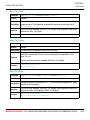
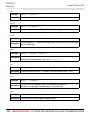
CHAPTER 1
Features . . . . . . . . . . . . . . . . . . . . . . . . . . . . . . . . . . . . . . . . . . . . . . . . . 2
Where to Start . . . . . . . . . . . . . . . . . . . . . . . . . . . . . . . . . . . . . . . . . . . . 3
mikroElektronika Associates License Statement and Limited Warranty . . . . . 4
IMPORTANT - READ CAREFULLY . . . . . . . . . . . . . . . . . . . . . . . . . . . 4
LIMITED WARRANTY . . . . . . . . . . . . . . . . . . . . . . . . . . . . . . . . . . . . . . 5
HIGH RISK ACTIVITIES . . . . . . . . . . . . . . . . . . . . . . . . . . . . . . . . . . . . 6
GENERAL PROVISIONS . . . . . . . . . . . . . . . . . . . . . . . . . . . . . . . . . . . 6
Technical Support . . . . . . . . . . . . . . . . . . . . . . . . . . . . . . . . . . . . . . . . . . . . . . 7
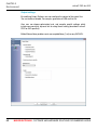
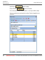
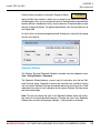
How to Register . . . . . . . . . . . . . . . . . . . . . . . . . . . . . . . . . . . . . . . . . . . . . . . . 8
Who Gets the License Key . . . . . . . . . . . . . . . . . . . . . . . . . . . . . . . . . . 8
How to Get License Key . . . . . . . . . . . . . . . . . . . . . . . . . . . . . . . . . . . . 8
After Receving the License Key . . . . . . . . . . . . . . . . . . . . . . . . . . . . . . 10
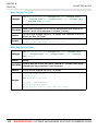
CHAPTER 2
IDE Overview . . . . . . . . . . . . . . . . . . . . . . . . . . . . . . . . . . . . . . . . . . . . . . . . . . 12
Main Menu Options . . . . . . . . . . . . . . . . . . . . . . . . . . . . . . . . . . . . . . . . . . . . . 13
File Menu Options . . . . . . . . . . . . . . . . . . . . . . . . . . . . . . . . . . . . . . . . . . . . . . 14
Edit Menu Options . . . . . . . . . . . . . . . . . . . . . . . . . . . . . . . . . . . . . . . . . . . . . . 15
Find Text . . . . . . . . . . . . . . . . . . . . . . . . . . . . . . . . . . . . . . . . . . . . . . . . 17
Replace Text . . . . . . . . . . . . . . . . . . . . . . . . . . . . . . . . . . . . . . . . . . . . . 17
Find In Files . . . . . . . . . . . . . . . . . . . . . . . . . . . . . . . . . . . . . . . . . . . . . . 18
Go To Line . . . . . . . . . . . . . . . . . . . . . . . . . . . . . . . . . . . . . . . . . . . . . . . 18
Regular expressions . . . . . . . . . . . . . . . . . . . . . . . . . . . . . . . . . . . . . . . 19
View Menu Options . . . . . . . . . . . . . . . . . . . . . . . . . . . . . . . . . . . . . . . . . . . . . 20
Toolbars . . . . . . . . . . . . . . . . . . . . . . . . . . . . . . . . . . . . . . . . . . . . . . . . . . . . . . 21
File Toolbar . . . . . . . . . . . . . . . . . . . . . . . . . . . . . . . . . . . . . . . . . . . . . . 21
Edit Toolbar . . . . . . . . . . . . . . . . . . . . . . . . . . . . . . . . . . . . . . . . . . . . . . 21
Advanced Edit Toolbar . . . . . . . . . . . . . . . . . . . . . . . . . . . . . . . . . . . . . . 22
Find/Replace Toolbar . . . . . . . . . . . . . . . . . . . . . . . . . . . . . . . . . . . . . . . 22
Project Toolbar . . . . . . . . . . . . . . . . . . . . . . . . . . . . . . . . . . . . . . . . . . . . 23
Build Toolbar . . . . . . . . . . . . . . . . . . . . . . . . . . . . . . . . . . . . . . . . . . . . . 23
Debugger . . . . . . . . . . . . . . . . . . . . . . . . . . . . . . . . . . . . . . . . . . . . . . . . 24
Styles Toolbar . . . . . . . . . . . . . . . . . . . . . . . . . . . . . . . . . . . . . . . . . . . . 25
Tools Toolbar . . . . . . . . . . . . . . . . . . . . . . . . . . . . . . . . . . . . . . . . . . . . . 25
Project Menu Options . . . . . . . . . . . . . . . . . . . . . . . . . . . . . . . . . . . . . . . . . . . 26
IV
MIKROELEKTRONIKA - SOFTWARE AND HARDWARE SOLUTIONS FOR EMBEDDED WORLD
mikroC PRO for AVR
Table of Contents
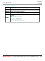
Run Menu Options . . . . . . . . . . . . . . . . . . . . . . . . . . . . . . . . . . . . . . . . . . . . . . 28
Tools Menu Options . . . . . . . . . . . . . . . . . . . . . . . . . . . . . . . . . . . . . . . . . . . . . 30
Help Menu Options . . . . . . . . . . . . . . . . . . . . . . . . . . . . . . . . . . . . . . . . . . . . . 31
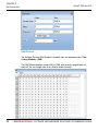
Keyboard Shortcuts . . . . . . . . . . . . . . . . . . . . . . . . . . . . . . . . . . . . . . . . . . . . . 32
mikroc pro for avr ide . . . . . . . . . . . . . . . . . . . . . . . . . . . . . . . . . . . . . . . . . . . . 35
IDE Overview . . . . . . . . . . . . . . . . . . . . . . . . . . . . . . . . . . . . . . . . . . . . . 35
Customizing IDE Layout . . . . . . . . . . . . . . . . . . . . . . . . . . . . . . . . . . . . . . . . . 37
Docking Windows . . . . . . . . . . . . . . . . . . . . . . . . . . . . . . . . . . . . . . . . . 37
Saving Layout . . . . . . . . . . . . . . . . . . . . . . . . . . . . . . . . . . . . . . . . . . . . 38
Auto Hide . . . . . . . . . . . . . . . . . . . . . . . . . . . . . . . . . . . . . . . . . . . . . . . . 39
Advanced Code Editor . . . . . . . . . . . . . . . . . . . . . . . . . . . . . . . . . . . . . . . . . . . 40
Advanced Editor Features . . . . . . . . . . . . . . . . . . . . . . . . . . . . . . . . . . . 40
Code Assistant . . . . . . . . . . . . . . . . . . . . . . . . . . . . . . . . . . . . . . . . . . . . 41
Code Folding . . . . . . . . . . . . . . . . . . . . . . . . . . . . . . . . . . . . . . . . . . . . . 42
Parameter Assistant . . . . . . . . . . . . . . . . . . . . . . . . . . . . . . . . . . . . . . . 43
Code Templates (Auto Complete) . . . . . . . . . . . . . . . . . . . . . . . . . . . . . 43
Auto Correct . . . . . . . . . . . . . . . . . . . . . . . . . . . . . . . . . . . . . . . . . . . . . 43
Spell Checker . . . . . . . . . . . . . . . . . . . . . . . . . . . . . . . . . . . . . . . . . . . . 44
Bookmarks . . . . . . . . . . . . . . . . . . . . . . . . . . . . . . . . . . . . . . . . . . . . . . . 44
Goto Line . . . . . . . . . . . . . . . . . . . . . . . . . . . . . . . . . . . . . . . . . . . . . . . . 44
Comment / Uncomment . . . . . . . . . . . . . . . . . . . . . . . . . . . . . . . . . . . . . 44
Code Explorer . . . . . . . . . . . . . . . . . . . . . . . . . . . . . . . . . . . . . . . . . . . . . . . . . 45
Routine List . . . . . . . . . . . . . . . . . . . . . . . . . . . . . . . . . . . . . . . . . . . . . . . . . . . 46
Project Manager . . . . . . . . . . . . . . . . . . . . . . . . . . . . . . . . . . . . . . . . . . . . . . . 47
Project Settings Window . . . . . . . . . . . . . . . . . . . . . . . . . . . . . . . . . . . . . . . . . 49
Library Manager . . . . . . . . . . . . . . . . . . . . . . . . . . . . . . . . . . . . . . . . . . . . . . . . 50
Error Window . . . . . . . . . . . . . . . . . . . . . . . . . . . . . . . . . . . . . . . . . . . . . . . . . . 52
Statistics . . . . . . . . . . . . . . . . . . . . . . . . . . . . . . . . . . . . . . . . . . . . . . . . . . . . . . 53
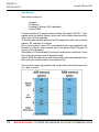
Memory Usage Windows . . . . . . . . . . . . . . . . . . . . . . . . . . . . . . . . . . . . 53
RAM Memory . . . . . . . . . . . . . . . . . . . . . . . . . . . . . . . . . . . . . . . . . . . . . 53
Rx Memory Space . . . . . . . . . . . . . . . . . . . . . . . . . . . . . . . . . . . . . . . . . 53
Data Memory Space . . . . . . . . . . . . . . . . . . . . . . . . . . . . . . . . . . . . . . . 54
Special Function Registers . . . . . . . . . . . . . . . . . . . . . . . . . . . . . . . . . . 54
General Purpose Registers . . . . . . . . . . . . . . . . . . . . . . . . . . . . . . . . . . 55
ROM Memory . . . . . . . . . . . . . . . . . . . . . . . . . . . . . . . . . . . . . . . . . . . . 55
ROM Memory Usage . . . . . . . . . . . . . . . . . . . . . . . . . . . . . . . . . . . . . . . 55
MIKROELEKTRONIKA - SOFTWARE AND HARDWARE SOLUTIONS FOR EMBEDDED WORLD
V
Table of Contents
mikroC PRO for AVR
ROM Memory Allocation . . . . . . . . . . . . . . . . . . . . . . . . . . . . . . . . . . . . 56
Procedures Windows . . . . . . . . . . . . . . . . . . . . . . . . . . . . . . . . . . . . . . . 56
Procedures Size Window . . . . . . . . . . . . . . . . . . . . . . . . . . . . . . . . . . . 57
Procedures Locations Window . . . . . . . . . . . . . . . . . . . . . . . . . . . . . . . 57
HTML Window . . . . . . . . . . . . . . . . . . . . . . . . . . . . . . . . . . . . . . . . . . . . 58
Macro Editor . . . . . . . . . . . . . . . . . . . . . . . . . . . . . . . . . . . . . . . . . . . . . . . . . . 59
Integrated Tools . . . . . . . . . . . . . . . . . . . . . . . . . . . . . . . . . . . . . . . . . . . . . . . . 60
USART Terminal . . . . . . . . . . . . . . . . . . . . . . . . . . . . . . . . . . . . . . . . . . 60
ASCII Chart . . . . . . . . . . . . . . . . . . . . . . . . . . . . . . . . . . . . . . . . . . . . . . 61
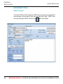
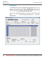
EEPROM Editor . . . . . . . . . . . . . . . . . . . . . . . . . . . . . . . . . . . . . . . . . . . 62
7 Segment Display Decoder . . . . . . . . . . . . . . . . . . . . . . . . . . . . . . . . . 63
UDP Terminal . . . . . . . . . . . . . . . . . . . . . . . . . . . . . . . . . . . . . . . . . . . . . 64
Graphic LCD Bitmap Editor . . . . . . . . . . . . . . . . . . . . . . . . . . . . . . . . . . 65
LCD Custom Character . . . . . . . . . . . . . . . . . . . . . . . . . . . . . . . . . . . . . 66
Options . . . . . . . . . . . . . . . . . . . . . . . . . . . . . . . . . . . . . . . . . . . . . . . . . . . . . . . 67
Code editor . . . . . . . . . . . . . . . . . . . . . . . . . . . . . . . . . . . . . . . . . . . . . . 67
Tools . . . . . . . . . . . . . . . . . . . . . . . . . . . . . . . . . . . . . . . . . . . . . . . . . . . 67
Output settings . . . . . . . . . . . . . . . . . . . . . . . . . . . . . . . . . . . . . . . . . . . 68
Regular Expressions . . . . . . . . . . . . . . . . . . . . . . . . . . . . . . . . . . . . . . . . . . . . 69
Introduction . . . . . . . . . . . . . . . . . . . . . . . . . . . . . . . . . . . . . . . . . . . . . . 69
Simple matches . . . . . . . . . . . . . . . . . . . . . . . . . . . . . . . . . . . . . . . . . . . 69
Escape sequences . . . . . . . . . . . . . . . . . . . . . . . . . . . . . . . . . . . . . . . . 69
Character classes . . . . . . . . . . . . . . . . . . . . . . . . . . . . . . . . . . . . . . . . . 70
Metacharacters . . . . . . . . . . . . . . . . . . . . . . . . . . . . . . . . . . . . . . . . . . . 70
Metacharacters - Line separators . . . . . . . . . . . . . . . . . . . . . . . . . . . . . 71
Metacharacters - Predefined classes . . . . . . . . . . . . . . . . . . . . . . . . . . 71
Metacharacters - Word boundaries . . . . . . . . . . . . . . . . . . . . . . . . . . . . 72
Metacharacters - Iterators . . . . . . . . . . . . . . . . . . . . . . . . . . . . . . . . . . . 72
Metacharacters - Alternatives . . . . . . . . . . . . . . . . . . . . . . . . . . . . . . . . 73
Metacharacters - Subexpressions . . . . . . . . . . . . . . . . . . . . . . . . . . . . . 74
Metacharacters - Backreferences . . . . . . . . . . . . . . . . . . . . . . . . . . . . . 74
mikroC PRO for AVR Command Line Options . . . . . . . . . . . . . . . . . . . . . . . . 75
tutorials . . . . . . . . . . . . . . . . . . . . . . . . . . . . . . . . . . . . . . . . . . . . . . . . . . . . . . 76
Projects . . . . . . . . . . . . . . . . . . . . . . . . . . . . . . . . . . . . . . . . . . . . . . . . . 76
New Project . . . . . . . . . . . . . . . . . . . . . . . . . . . . . . . . . . . . . . . . . . . . . . 76
New Project Wizard Steps . . . . . . . . . . . . . . . . . . . . . . . . . . . . . . . . . . . 77
VI
MIKROELEKTRONIKA - SOFTWARE AND HARDWARE SOLUTIONS FOR EMBEDDED WORLD
mikroC PRO for AVR
Table of Contents
Customizing Projects . . . . . . . . . . . . . . . . . . . . . . . . . . . . . . . . . . . . . . . . . . . . 80
Edit Project . . . . . . . . . . . . . . . . . . . . . . . . . . . . . . . . . . . . . . . . . . . . . . 80
Managing Project Group . . . . . . . . . . . . . . . . . . . . . . . . . . . . . . . . . . . . 80
Add/Remove Files from Project . . . . . . . . . . . . . . . . . . . . . . . . . . . . . . . 80
Project Level Defines: . . . . . . . . . . . . . . . . . . . . . . . . . . . . . . . . . . . . . . 82
Source Files . . . . . . . . . . . . . . . . . . . . . . . . . . . . . . . . . . . . . . . . . . . . . . . . . . . 83
Managing Source Files . . . . . . . . . . . . . . . . . . . . . . . . . . . . . . . . . . . . . 83
Creating new source file . . . . . . . . . . . . . . . . . . . . . . . . . . . . . . . . . . . . 83
Opening an existing file . . . . . . . . . . . . . . . . . . . . . . . . . . . . . . . . . . . . . 83
Printing an open file . . . . . . . . . . . . . . . . . . . . . . . . . . . . . . . . . . . . . . . . 84
Saving file . . . . . . . . . . . . . . . . . . . . . . . . . . . . . . . . . . . . . . . . . . . . . . . 84
Saving file under a different name . . . . . . . . . . . . . . . . . . . . . . . . . . . . 84
Closing file . . . . . . . . . . . . . . . . . . . . . . . . . . . . . . . . . . . . . . . . . . . . . . . 84
Clean Project Folder . . . . . . . . . . . . . . . . . . . . . . . . . . . . . . . . . . . . . . . . . . . . 85
Clean Project Folder . . . . . . . . . . . . . . . . . . . . . . . . . . . . . . . . . . . . . . . 85
Compilation . . . . . . . . . . . . . . . . . . . . . . . . . . . . . . . . . . . . . . . . . . . . . . . . . . . 86
Output Files . . . . . . . . . . . . . . . . . . . . . . . . . . . . . . . . . . . . . . . . . . . . . . 86
Assembly View . . . . . . . . . . . . . . . . . . . . . . . . . . . . . . . . . . . . . . . . . . . 86
Error Messages . . . . . . . . . . . . . . . . . . . . . . . . . . . . . . . . . . . . . . . . . . . . . . . . 87
Compiler Error Messages . . . . . . . . . . . . . . . . . . . . . . . . . . . . . . . . . . . 87
Compiler Warning Messages . . . . . . . . . . . . . . . . . . . . . . . . . . . . . . . . 90
Linker Error Messages . . . . . . . . . . . . . . . . . . . . . . . . . . . . . . . . . . . . . 90
Software Simulator Overview . . . . . . . . . . . . . . . . . . . . . . . . . . . . . . . . . . . . . 91
Watch Window . . . . . . . . . . . . . . . . . . . . . . . . . . . . . . . . . . . . . . . . . . . . 91
Stopwatch Window . . . . . . . . . . . . . . . . . . . . . . . . . . . . . . . . . . . . . . . . 93
RAM Window . . . . . . . . . . . . . . . . . . . . . . . . . . . . . . . . . . . . . . . . . . . . . 94
Software Simulator Options . . . . . . . . . . . . . . . . . . . . . . . . . . . . . . . . . . . . . . . 95
Creating New Library . . . . . . . . . . . . . . . . . . . . . . . . . . . . . . . . . . . . . . . . . . . . 96
Multiple Library Versions . . . . . . . . . . . . . . . . . . . . . . . . . . . . . . . . . . . . 96
MIKROELEKTRONIKA - SOFTWARE AND HARDWARE SOLUTIONS FOR EMBEDDED WORLD
VII
Table of Contents
mikroC PRO for AVR
CHAPTER 3
Notes: . . . . . . . . . . . . . . . . . . . . . . . . . . . . . . . . . . . . . . . . . . . . . . . . . . 98
ANSI Standard Issues . . . . . . . . . . . . . . . . . . . . . . . . . . . . . . . . . . . . . . . . . . . 98
Divergence from the ANI C Standard . . . . . . . . . . . . . . . . . . . . . . . . . . . . . . . 98
Predefined Globals and Constants . . . . . . . . . . . . . . . . . . . . . . . . . . . . . . . . . 99
Predefined project level defines . . . . . . . . . . . . . . . . . . . . . . . . . . . . . . 99
Accessing Individual Bits . . . . . . . . . . . . . . . . . . . . . . . . . . . . . . . . . . . . . . . . . 100
Accessing Individual Bits Of Variables . . . . . . . . . . . . . . . . . . . . . . . . . 100
sbit type . . . . . . . . . . . . . . . . . . . . . . . . . . . . . . . . . . . . . . . . . . . . . . . . . 100
bit type . . . . . . . . . . . . . . . . . . . . . . . . . . . . . . . . . . . . . . . . . . . . . . . . . . 101
Interrupts . . . . . . . . . . . . . . . . . . . . . . . . . . . . . . . . . . . . . . . . . . . . . . . . . . . . . 102
Function Calls from Interrupt . . . . . . . . . . . . . . . . . . . . . . . . . . . . . . . . . 102
Linker Directives . . . . . . . . . . . . . . . . . . . . . . . . . . . . . . . . . . . . . . . . . . . . . . . 104
Directive absolute . . . . . . . . . . . . . . . . . . . . . . . . . . . . . . . . . . . . . . . . . 104
Directive org . . . . . . . . . . . . . . . . . . . . . . . . . . . . . . . . . . . . . . . . . . . . . 104
Directive orgal . . . . . . . . . . . . . . . . . . . . . . . . . . . . . . . . . . . . . . . . . . . . 105
Indirect Function Calls . . . . . . . . . . . . . . . . . . . . . . . . . . . . . . . . . . . . . . . . . . . 105
Built-in Routines . . . . . . . . . . . . . . . . . . . . . . . . . . . . . . . . . . . . . . . . . . . . . . . . 106
Lo . . . . . . . . . . . . . . . . . . . . . . . . . . . . . . . . . . . . . . . . . . . . . . . . . . . . . . 106
Hi . . . . . . . . . . . . . . . . . . . . . . . . . . . . . . . . . . . . . . . . . . . . . . . . . . . . . . 107
Higher . . . . . . . . . . . . . . . . . . . . . . . . . . . . . . . . . . . . . . . . . . . . . . . . . . 107
Highest . . . . . . . . . . . . . . . . . . . . . . . . . . . . . . . . . . . . . . . . . . . . . . . . . . 107
Delay_us . . . . . . . . . . . . . . . . . . . . . . . . . . . . . . . . . . . . . . . . . . . . . . . . 108
Delay_ms . . . . . . . . . . . . . . . . . . . . . . . . . . . . . . . . . . . . . . . . . . . . . . . . 108
Vdelay_ms . . . . . . . . . . . . . . . . . . . . . . . . . . . . . . . . . . . . . . . . . . . . . . . 108
Delay_Cyc . . . . . . . . . . . . . . . . . . . . . . . . . . . . . . . . . . . . . . . . . . . . . . . 109
Clock_kHz . . . . . . . . . . . . . . . . . . . . . . . . . . . . . . . . . . . . . . . . . . . . . . . 109
Clock_MHz . . . . . . . . . . . . . . . . . . . . . . . . . . . . . . . . . . . . . . . . . . . . . . 109
Get_Fosc_kHz . . . . . . . . . . . . . . . . . . . . . . . . . . . . . . . . . . . . . . . . . . . . 110
Code Optimization . . . . . . . . . . . . . . . . . . . . . . . . . . . . . . . . . . . . . . . . . . . . . . 110
Constant folding . . . . . . . . . . . . . . . . . . . . . . . . . . . . . . . . . . . . . . . . . . . 110
Constant propagation . . . . . . . . . . . . . . . . . . . . . . . . . . . . . . . . . . . . . . 110
Copy propagation . . . . . . . . . . . . . . . . . . . . . . . . . . . . . . . . . . . . . . . . . 110
Value numbering . . . . . . . . . . . . . . . . . . . . . . . . . . . . . . . . . . . . . . . . . . 110
"Dead code" ellimination . . . . . . . . . . . . . . . . . . . . . . . . . . . . . . . . . . . . 110
Stack allocation . . . . . . . . . . . . . . . . . . . . . . . . . . . . . . . . . . . . . . . . . . . 111
VIII
MIKROELEKTRONIKA - SOFTWARE AND HARDWARE SOLUTIONS FOR EMBEDDED WORLD
mikroC PRO for AVR
Table of Contents
Local vars optimization . . . . . . . . . . . . . . . . . . . . . . . . . . . . . . . . . . . . . 111
Better code generation and local optimization . . . . . . . . . . . . . . . . . . . 111
CHAPTER 4
Types Efficiency . . . . . . . . . . . . . . . . . . . . . . . . . . . . . . . . . . . . . . . . . . . 113
Nested Calls Limitations . . . . . . . . . . . . . . . . . . . . . . . . . . . . . . . . . . . . 114
Important notes: . . . . . . . . . . . . . . . . . . . . . . . . . . . . . . . . . . . . . . . . . . . 114
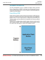
AVR Memory Organization . . . . . . . . . . . . . . . . . . . . . . . . . . . . . . . . . . . . . . . 115
Program Memory (ROM) . . . . . . . . . . . . . . . . . . . . . . . . . . . . . . . . . . . . 115
Data Memory . . . . . . . . . . . . . . . . . . . . . . . . . . . . . . . . . . . . . . . . . . . . . 116
Memory Type Specifiers . . . . . . . . . . . . . . . . . . . . . . . . . . . . . . . . . . . . . . . . . 117
code . . . . . . . . . . . . . . . . . . . . . . . . . . . . . . . . . . . . . . . . . . . . . . . . . . . . 117
data . . . . . . . . . . . . . . . . . . . . . . . . . . . . . . . . . . . . . . . . . . . . . . . . . . . . 117
rx . . . . . . . . . . . . . . . . . . . . . . . . . . . . . . . . . . . . . . . . . . . . . . . . . . . . . . 118
io . . . . . . . . . . . . . . . . . . . . . . . . . . . . . . . . . . . . . . . . . . . . . . . . . . . . . . 118
sfr . . . . . . . . . . . . . . . . . . . . . . . . . . . . . . . . . . . . . . . . . . . . . . . . . . . . . . 118
CHAPTER 5
mikroC PRO for AVR language Reference . . . . . . . . . . . . . . . . . . . . . . . . . . . 120
Lexical Elements Overview . . . . . . . . . . . . . . . . . . . . . . . . . . . . . . . . . . . . . . . 122
Whitespace . . . . . . . . . . . . . . . . . . . . . . . . . . . . . . . . . . . . . . . . . . . . . . . . . . . 122
Whitespace in Strings . . . . . . . . . . . . . . . . . . . . . . . . . . . . . . . . . . . . . . 122
Line Splicing with Backslash (\) . . . . . . . . . . . . . . . . . . . . . . . . . . . . . . . 123
Comments . . . . . . . . . . . . . . . . . . . . . . . . . . . . . . . . . . . . . . . . . . . . . . . . . . . . 123
C comments . . . . . . . . . . . . . . . . . . . . . . . . . . . . . . . . . . . . . . . . . . . . . 123
C++ comments . . . . . . . . . . . . . . . . . . . . . . . . . . . . . . . . . . . . . . . . . . . 124
Nested comments . . . . . . . . . . . . . . . . . . . . . . . . . . . . . . . . . . . . . . . . . 124
Tokens . . . . . . . . . . . . . . . . . . . . . . . . . . . . . . . . . . . . . . . . . . . . . . . . . . . . . . . 125
Token Extraction Example . . . . . . . . . . . . . . . . . . . . . . . . . . . . . . . . . . . 125
Constants . . . . . . . . . . . . . . . . . . . . . . . . . . . . . . . . . . . . . . . . . . . . . . . . . . . . . 126
Integer Constants . . . . . . . . . . . . . . . . . . . . . . . . . . . . . . . . . . . . . . . . . . . . . . 127
Long and Unsigned Suffixes . . . . . . . . . . . . . . . . . . . . . . . . . . . . . . . . . 127
Decimal . . . . . . . . . . . . . . . . . . . . . . . . . . . . . . . . . . . . . . . . . . . . . . . . . 127
Hexadecimal . . . . . . . . . . . . . . . . . . . . . . . . . . . . . . . . . . . . . . . . . . . . . 128
Binary . . . . . . . . . . . . . . . . . . . . . . . . . . . . . . . . . . . . . . . . . . . . . . . . . . . 128
Octal . . . . . . . . . . . . . . . . . . . . . . . . . . . . . . . . . . . . . . . . . . . . . . . . . . . 128
MIKROELEKTRONIKA - SOFTWARE AND HARDWARE SOLUTIONS FOR EMBEDDED WORLD
IX
Table of Contents
mikroC PRO for AVR
Floating Point Constants . . . . . . . . . . . . . . . . . . . . . . . . . . . . . . . . . . . . . . . . . 129
Character Constants . . . . . . . . . . . . . . . . . . . . . . . . . . . . . . . . . . . . . . . . . . . . 130
Escape Sequences . . . . . . . . . . . . . . . . . . . . . . . . . . . . . . . . . . . . . . . . 130
Disambiguation . . . . . . . . . . . . . . . . . . . . . . . . . . . . . . . . . . . . . . . . . . . 131
String Constants . . . . . . . . . . . . . . . . . . . . . . . . . . . . . . . . . . . . . . . . . . . . . . . 132
Line Continuation with Backslash . . . . . . . . . . . . . . . . . . . . . . . . . . . . . 132
Enumeration Constants . . . . . . . . . . . . . . . . . . . . . . . . . . . . . . . . . . . . . . . . . . 133
Constant Expressions . . . . . . . . . . . . . . . . . . . . . . . . . . . . . . . . . . . . . . . . . . . 135
Keywords . . . . . . . . . . . . . . . . . . . . . . . . . . . . . . . . . . . . . . . . . . . . . . . . . . . . . 136
Identifiers . . . . . . . . . . . . . . . . . . . . . . . . . . . . . . . . . . . . . . . . . . . . . . . . . . . . . 137
Case Sensitivity . . . . . . . . . . . . . . . . . . . . . . . . . . . . . . . . . . . . . . . . . . . 137
Uniqueness and Scope . . . . . . . . . . . . . . . . . . . . . . . . . . . . . . . . . . . . . 137
Identifier Examples . . . . . . . . . . . . . . . . . . . . . . . . . . . . . . . . . . . . . . . . 137
Punctuators . . . . . . . . . . . . . . . . . . . . . . . . . . . . . . . . . . . . . . . . . . . . . . . . . . . 138
Brackets . . . . . . . . . . . . . . . . . . . . . . . . . . . . . . . . . . . . . . . . . . . . . . . . . 138
Parentheses . . . . . . . . . . . . . . . . . . . . . . . . . . . . . . . . . . . . . . . . . . . . . . 138
Braces . . . . . . . . . . . . . . . . . . . . . . . . . . . . . . . . . . . . . . . . . . . . . . . . . . 139
Comma . . . . . . . . . . . . . . . . . . . . . . . . . . . . . . . . . . . . . . . . . . . . . . . . . 139
Semicolon . . . . . . . . . . . . . . . . . . . . . . . . . . . . . . . . . . . . . . . . . . . . . . . 139
Colon . . . . . . . . . . . . . . . . . . . . . . . . . . . . . . . . . . . . . . . . . . . . . . . . . . . 140
Asterisk (Pointer Declaration) . . . . . . . . . . . . . . . . . . . . . . . . . . . . . . . . 140
Equal Sign . . . . . . . . . . . . . . . . . . . . . . . . . . . . . . . . . . . . . . . . . . . . . . . 140
Pound Sign (Preprocessor Directive) . . . . . . . . . . . . . . . . . . . . . . . . . . 141
Concepts . . . . . . . . . . . . . . . . . . . . . . . . . . . . . . . . . . . . . . . . . . . . . . . . . . . . . 142
Objects . . . . . . . . . . . . . . . . . . . . . . . . . . . . . . . . . . . . . . . . . . . . . . . . . . . . . . . 142
Objects and Declarations . . . . . . . . . . . . . . . . . . . . . . . . . . . . . . . . . . . 142
Lvalues . . . . . . . . . . . . . . . . . . . . . . . . . . . . . . . . . . . . . . . . . . . . . . . . . 143
Rvalues . . . . . . . . . . . . . . . . . . . . . . . . . . . . . . . . . . . . . . . . . . . . . . . . . 143
Scope and Visibility . . . . . . . . . . . . . . . . . . . . . . . . . . . . . . . . . . . . . . . . . . . . . 144
Scope . . . . . . . . . . . . . . . . . . . . . . . . . . . . . . . . . . . . . . . . . . . . . . . . . . . 144
Visibility . . . . . . . . . . . . . . . . . . . . . . . . . . . . . . . . . . . . . . . . . . . . . . . . . 144
Name Spaces . . . . . . . . . . . . . . . . . . . . . . . . . . . . . . . . . . . . . . . . . . . . . . . . . 146
Duration . . . . . . . . . . . . . . . . . . . . . . . . . . . . . . . . . . . . . . . . . . . . . . . . . . . . . . 147
Static Duration . . . . . . . . . . . . . . . . . . . . . . . . . . . . . . . . . . . . . . . . . . . . 147
Local Duration . . . . . . . . . . . . . . . . . . . . . . . . . . . . . . . . . . . . . . . . . . . . 147
Types . . . . . . . . . . . . . . . . . . . . . . . . . . . . . . . . . . . . . . . . . . . . . . . . . . . . . . . . 149
X
MIKROELEKTRONIKA - SOFTWARE AND HARDWARE SOLUTIONS FOR EMBEDDED WORLD
mikroC PRO for AVR
Table of Contents
Type Categories . . . . . . . . . . . . . . . . . . . . . . . . . . . . . . . . . . . . . . . . . . 149
Fundamental Types . . . . . . . . . . . . . . . . . . . . . . . . . . . . . . . . . . . . . . . . . . . . . 150
Arithmetic Types . . . . . . . . . . . . . . . . . . . . . . . . . . . . . . . . . . . . . . . . . . . . . . . 150
Integral Types . . . . . . . . . . . . . . . . . . . . . . . . . . . . . . . . . . . . . . . . . . . . 150
Floating-point Types . . . . . . . . . . . . . . . . . . . . . . . . . . . . . . . . . . . . . . . 151
Enumerations . . . . . . . . . . . . . . . . . . . . . . . . . . . . . . . . . . . . . . . . . . . . . . . . . . 152
Enumeration Declaration . . . . . . . . . . . . . . . . . . . . . . . . . . . . . . . . . . . . 152
Anonymous Enum Type . . . . . . . . . . . . . . . . . . . . . . . . . . . . . . . . . . . . 153
Enumeration Scope . . . . . . . . . . . . . . . . . . . . . . . . . . . . . . . . . . . . . . . . 153
Void Type . . . . . . . . . . . . . . . . . . . . . . . . . . . . . . . . . . . . . . . . . . . . . . . . . . . . . 154
Void Functions . . . . . . . . . . . . . . . . . . . . . . . . . . . . . . . . . . . . . . . . . . . . 154
Generic Pointers . . . . . . . . . . . . . . . . . . . . . . . . . . . . . . . . . . . . . . . . . . 154
Derived Types . . . . . . . . . . . . . . . . . . . . . . . . . . . . . . . . . . . . . . . . . . . . . . . . . 155
Arrays . . . . . . . . . . . . . . . . . . . . . . . . . . . . . . . . . . . . . . . . . . . . . . . . . . . . . . . . 155
Array Declaration . . . . . . . . . . . . . . . . . . . . . . . . . . . . . . . . . . . . . . . . . . 155
Arrays in Expressions . . . . . . . . . . . . . . . . . . . . . . . . . . . . . . . . . . . . . . 156
Multi-dimensional Arrays . . . . . . . . . . . . . . . . . . . . . . . . . . . . . . . . . . . . 156
Pointers . . . . . . . . . . . . . . . . . . . . . . . . . . . . . . . . . . . . . . . . . . . . . . . . . . . . . . 158
Pointer Declarations . . . . . . . . . . . . . . . . . . . . . . . . . . . . . . . . . . . . . . . 158
Null Pointers . . . . . . . . . . . . . . . . . . . . . . . . . . . . . . . . . . . . . . . . . . . . . 159
Function Pointers . . . . . . . . . . . . . . . . . . . . . . . . . . . . . . . . . . . . . . . . . . . . . . . 160
Assign an address to a Function Pointer . . . . . . . . . . . . . . . . . . . . . . . 160
Pointer Arithmetic . . . . . . . . . . . . . . . . . . . . . . . . . . . . . . . . . . . . . . . . . . . . . . . 161
Arrays and Pointers . . . . . . . . . . . . . . . . . . . . . . . . . . . . . . . . . . . . . . . . 161
Assignment and Comparison . . . . . . . . . . . . . . . . . . . . . . . . . . . . . . . . 162
Pointer Addition . . . . . . . . . . . . . . . . . . . . . . . . . . . . . . . . . . . . . . . . . . . 163
Pointer Subtraction . . . . . . . . . . . . . . . . . . . . . . . . . . . . . . . . . . . . . . . . 164
Structures . . . . . . . . . . . . . . . . . . . . . . . . . . . . . . . . . . . . . . . . . . . . . . . . . . . . . 165
Structure Declaration and Initialization . . . . . . . . . . . . . . . . . . . . . . . . . 165
Untagged Structures and Typedefs . . . . . . . . . . . . . . . . . . . . . . . . . . . . 166
Working with Structures . . . . . . . . . . . . . . . . . . . . . . . . . . . . . . . . . . . . . . . . . . 167
Assignment . . . . . . . . . . . . . . . . . . . . . . . . . . . . . . . . . . . . . . . . . . . . . . 167
Size of Structure . . . . . . . . . . . . . . . . . . . . . . . . . . . . . . . . . . . . . . . . . . 167
Structures and Functions . . . . . . . . . . . . . . . . . . . . . . . . . . . . . . . . . . . . 167
Structure Member Access . . . . . . . . . . . . . . . . . . . . . . . . . . . . . . . . . . . . . . . . 168
Accessing Nested Structures . . . . . . . . . . . . . . . . . . . . . . . . . . . . . . . . 169
MIKROELEKTRONIKA - SOFTWARE AND HARDWARE SOLUTIONS FOR EMBEDDED WORLD
XI
Table of Contents
mikroC PRO for AVR
Structure Uniqueness . . . . . . . . . . . . . . . . . . . . . . . . . . . . . . . . . . . . . . 169
Unions . . . . . . . . . . . . . . . . . . . . . . . . . . . . . . . . . . . . . . . . . . . . . . . . . . . . . . . 170
Union Declaration . . . . . . . . . . . . . . . . . . . . . . . . . . . . . . . . . . . . . . . . . 170
Size of Union . . . . . . . . . . . . . . . . . . . . . . . . . . . . . . . . . . . . . . . . . . . . . 170
Union Member Access . . . . . . . . . . . . . . . . . . . . . . . . . . . . . . . . . . . . . . 170
Bit Fields . . . . . . . . . . . . . . . . . . . . . . . . . . . . . . . . . . . . . . . . . . . . . . . . . . . . . 172
Bit Fields Declaration . . . . . . . . . . . . . . . . . . . . . . . . . . . . . . . . . . . . . . . 172
Bit Fields Access . . . . . . . . . . . . . . . . . . . . . . . . . . . . . . . . . . . . . . . . . . 173
Types Conversions . . . . . . . . . . . . . . . . . . . . . . . . . . . . . . . . . . . . . . . . . . . . . 174
Standard Conversions . . . . . . . . . . . . . . . . . . . . . . . . . . . . . . . . . . . . . . . . . . . 175
Arithmetic Conversions . . . . . . . . . . . . . . . . . . . . . . . . . . . . . . . . . . . . . 175
In details: . . . . . . . . . . . . . . . . . . . . . . . . . . . . . . . . . . . . . . . . . . . . . . . . 175
Pointer Conversions . . . . . . . . . . . . . . . . . . . . . . . . . . . . . . . . . . . . . . . 176
Explicit Types Conversions (Typecasting) . . . . . . . . . . . . . . . . . . . . . . . . . . . . 177
Declarations . . . . . . . . . . . . . . . . . . . . . . . . . . . . . . . . . . . . . . . . . . . . . . . . . . . 178
Declarations and Definitions . . . . . . . . . . . . . . . . . . . . . . . . . . . . . . . . . 178
Declarations and Declarators . . . . . . . . . . . . . . . . . . . . . . . . . . . . . . . . 179
Linkage . . . . . . . . . . . . . . . . . . . . . . . . . . . . . . . . . . . . . . . . . . . . . . . . . . . . . . 180
Linkage Rules . . . . . . . . . . . . . . . . . . . . . . . . . . . . . . . . . . . . . . . . . . . . 180
Internal Linkage Rules . . . . . . . . . . . . . . . . . . . . . . . . . . . . . . . . . . . . . . 180
External Linkage Rules . . . . . . . . . . . . . . . . . . . . . . . . . . . . . . . . . . . . . 180
Storage Classes . . . . . . . . . . . . . . . . . . . . . . . . . . . . . . . . . . . . . . . . . . . . . . . 181
Auto . . . . . . . . . . . . . . . . . . . . . . . . . . . . . . . . . . . . . . . . . . . . . . . . . . . . 181
Register . . . . . . . . . . . . . . . . . . . . . . . . . . . . . . . . . . . . . . . . . . . . . . . . . 181
Static . . . . . . . . . . . . . . . . . . . . . . . . . . . . . . . . . . . . . . . . . . . . . . . . . . . 182
Extern . . . . . . . . . . . . . . . . . . . . . . . . . . . . . . . . . . . . . . . . . . . . . . . . . . 182
Type Qualifiers . . . . . . . . . . . . . . . . . . . . . . . . . . . . . . . . . . . . . . . . . . . . . . . . . 183
Qualifier const . . . . . . . . . . . . . . . . . . . . . . . . . . . . . . . . . . . . . . . . . . . . 183
Qualifier volatile . . . . . . . . . . . . . . . . . . . . . . . . . . . . . . . . . . . . . . . . . . . 183
Typedef Specifier . . . . . . . . . . . . . . . . . . . . . . . . . . . . . . . . . . . . . . . . . . . . . . . 184
asm Declaration . . . . . . . . . . . . . . . . . . . . . . . . . . . . . . . . . . . . . . . . . . . . . . . . 185
Automatic Initialization . . . . . . . . . . . . . . . . . . . . . . . . . . . . . . . . . . . . . . 186
Functions . . . . . . . . . . . . . . . . . . . . . . . . . . . . . . . . . . . . . . . . . . . . . . . . . . . . . 187
Function Prototypes . . . . . . . . . . . . . . . . . . . . . . . . . . . . . . . . . . . . . . . . 188
Function Definition . . . . . . . . . . . . . . . . . . . . . . . . . . . . . . . . . . . . . . . . . . . . . . 188
Functions reentrancy . . . . . . . . . . . . . . . . . . . . . . . . . . . . . . . . . . . . . . . 189
XII
MIKROELEKTRONIKA - SOFTWARE AND HARDWARE SOLUTIONS FOR EMBEDDED WORLD
mikroC PRO for AVR
Table of Contents
Function Calls and Argument Conversions . . . . . . . . . . . . . . . . . . . . . . . . . . . 190
Function Calls . . . . . . . . . . . . . . . . . . . . . . . . . . . . . . . . . . . . . . . . . . . . 190
Argument Conversions . . . . . . . . . . . . . . . . . . . . . . . . . . . . . . . . . . . . . 191
Operators . . . . . . . . . . . . . . . . . . . . . . . . . . . . . . . . . . . . . . . . . . . . . . . . . . . . . 193
Operators Precedence and Associativity . . . . . . . . . . . . . . . . . . . . . . . . . . . . . 194
Arithmetic Operators . . . . . . . . . . . . . . . . . . . . . . . . . . . . . . . . . . . . . . . . . . . . 195
Arithmetic Operators Overview . . . . . . . . . . . . . . . . . . . . . . . . . . . . . . . 195
Binary Arithmetic Operators . . . . . . . . . . . . . . . . . . . . . . . . . . . . . . . . . . 195
Unary Arithmetic Operators . . . . . . . . . . . . . . . . . . . . . . . . . . . . . . . . . . 196
Relational Operators . . . . . . . . . . . . . . . . . . . . . . . . . . . . . . . . . . . . . . . . . . . . 197
Relational Operators Overview . . . . . . . . . . . . . . . . . . . . . . . . . . . . . . . 197
Relational Operators in Expressions . . . . . . . . . . . . . . . . . . . . . . . . . . . 197
Bitwise Operators . . . . . . . . . . . . . . . . . . . . . . . . . . . . . . . . . . . . . . . . . . . . . . 198
Bitwise Operators Overview . . . . . . . . . . . . . . . . . . . . . . . . . . . . . . . . . 198
Logical Operations on Bit Level . . . . . . . . . . . . . . . . . . . . . . . . . . . . . . . 198
Bitwise Shift Operators . . . . . . . . . . . . . . . . . . . . . . . . . . . . . . . . . . . . . 199
Bitwise vs. Logical . . . . . . . . . . . . . . . . . . . . . . . . . . . . . . . . . . . . . . . . . 199
Logical Operators . . . . . . . . . . . . . . . . . . . . . . . . . . . . . . . . . . . . . . . . . . . . . . 200
Logical Operators Overview . . . . . . . . . . . . . . . . . . . . . . . . . . . . . . . . . 200
Logical Operations . . . . . . . . . . . . . . . . . . . . . . . . . . . . . . . . . . . . . . . . . 200
Logical Expressions and Side Effects . . . . . . . . . . . . . . . . . . . . . . . . . . . . . . . 201
Logical vs. Bitwise . . . . . . . . . . . . . . . . . . . . . . . . . . . . . . . . . . . . . . . . . . . . . . 201
Conditional Operator ? : . . . . . . . . . . . . . . . . . . . . . . . . . . . . . . . . . . . . . . . . . 202
Conditional Operator Rules . . . . . . . . . . . . . . . . . . . . . . . . . . . . . . . . . . 202
Assignment Operators . . . . . . . . . . . . . . . . . . . . . . . . . . . . . . . . . . . . . . . . . . . 203
Simple Assignment Operator . . . . . . . . . . . . . . . . . . . . . . . . . . . . . . . . . 203
Compound Assignment Operators . . . . . . . . . . . . . . . . . . . . . . . . . . . . 203
Assignment Rules . . . . . . . . . . . . . . . . . . . . . . . . . . . . . . . . . . . . . . . . . 204
Sizeof Operator . . . . . . . . . . . . . . . . . . . . . . . . . . . . . . . . . . . . . . . . . . . . . . . . 205
Sizeof Applied to Expression . . . . . . . . . . . . . . . . . . . . . . . . . . . . . . . . . 205
Sizeof Applied to Type . . . . . . . . . . . . . . . . . . . . . . . . . . . . . . . . . . . . . . 205
Expressions . . . . . . . . . . . . . . . . . . . . . . . . . . . . . . . . . . . . . . . . . . . . . . 206
Comma Expressions . . . . . . . . . . . . . . . . . . . . . . . . . . . . . . . . . . . . . . . . . . . . 207
Note . . . . . . . . . . . . . . . . . . . . . . . . . . . . . . . . . . . . . . . . . . . . . . . . . . . . 207
Statements . . . . . . . . . . . . . . . . . . . . . . . . . . . . . . . . . . . . . . . . . . . . . . . . . . . . 208
Labeled Statements . . . . . . . . . . . . . . . . . . . . . . . . . . . . . . . . . . . . . . . . 208
MIKROELEKTRONIKA - SOFTWARE AND HARDWARE SOLUTIONS FOR EMBEDDED WORLD
XIII
Table of Contents
mikroC PRO for AVR
Expression Statements . . . . . . . . . . . . . . . . . . . . . . . . . . . . . . . . . . . . . . . . . . 209
Selection Statements . . . . . . . . . . . . . . . . . . . . . . . . . . . . . . . . . . . . . . . . . . . . 209
If Statement . . . . . . . . . . . . . . . . . . . . . . . . . . . . . . . . . . . . . . . . . . . . . . . . . . . 210
Nested If statements . . . . . . . . . . . . . . . . . . . . . . . . . . . . . . . . . . . . . . . 210
Note . . . . . . . . . . . . . . . . . . . . . . . . . . . . . . . . . . . . . . . . . . . . . . . . . . . . 210
Switch Statement . . . . . . . . . . . . . . . . . . . . . . . . . . . . . . . . . . . . . . . . . . . . . . . 211
Nested switch . . . . . . . . . . . . . . . . . . . . . . . . . . . . . . . . . . . . . . . . . . . . 212
Iteration Statements (Loops) . . . . . . . . . . . . . . . . . . . . . . . . . . . . . . . . . . . . . . 212
While Statement . . . . . . . . . . . . . . . . . . . . . . . . . . . . . . . . . . . . . . . . . . . . . . . 212
Do Statement . . . . . . . . . . . . . . . . . . . . . . . . . . . . . . . . . . . . . . . . . . . . . . . . . . 213
For Statement . . . . . . . . . . . . . . . . . . . . . . . . . . . . . . . . . . . . . . . . . . . . . . . . . 214
Jump Statements . . . . . . . . . . . . . . . . . . . . . . . . . . . . . . . . . . . . . . . . . . . . . . . 215
Break and Continue Statements . . . . . . . . . . . . . . . . . . . . . . . . . . . . . . . . . . . 215
Break Statement . . . . . . . . . . . . . . . . . . . . . . . . . . . . . . . . . . . . . . . . . . 215
Continue Statement . . . . . . . . . . . . . . . . . . . . . . . . . . . . . . . . . . . . . . . . 215
Goto Statement . . . . . . . . . . . . . . . . . . . . . . . . . . . . . . . . . . . . . . . . . . . . . . . . 216
Return Statement . . . . . . . . . . . . . . . . . . . . . . . . . . . . . . . . . . . . . . . . . . . . . . . 217
Compound Statements (Blocks) . . . . . . . . . . . . . . . . . . . . . . . . . . . . . . . . . . . 217
Preprocessor . . . . . . . . . . . . . . . . . . . . . . . . . . . . . . . . . . . . . . . . . . . . . . . . . . 218
Preprocessor Directives . . . . . . . . . . . . . . . . . . . . . . . . . . . . . . . . . . . . . . . . . . 219
Line Continuation with Backslash (\) . . . . . . . . . . . . . . . . . . . . . . . . . . . 219
Macros . . . . . . . . . . . . . . . . . . . . . . . . . . . . . . . . . . . . . . . . . . . . . . . . . . . . . . . 220
Macros with Parameters . . . . . . . . . . . . . . . . . . . . . . . . . . . . . . . . . . . . . . . . . 221
Undefining Macros . . . . . . . . . . . . . . . . . . . . . . . . . . . . . . . . . . . . . . . . . 222
File Inclusion . . . . . . . . . . . . . . . . . . . . . . . . . . . . . . . . . . . . . . . . . . . . . . . . . . 223
Explicit Path . . . . . . . . . . . . . . . . . . . . . . . . . . . . . . . . . . . . . . . . . . . . . . 223
Note . . . . . . . . . . . . . . . . . . . . . . . . . . . . . . . . . . . . . . . . . . . . . . . . . . . . 223
Preprocessor Operators . . . . . . . . . . . . . . . . . . . . . . . . . . . . . . . . . . . . . . . . . 224
Operator # . . . . . . . . . . . . . . . . . . . . . . . . . . . . . . . . . . . . . . . . . . . . . . . 224
Operator ## . . . . . . . . . . . . . . . . . . . . . . . . . . . . . . . . . . . . . . . . . . . . . . 224
Note . . . . . . . . . . . . . . . . . . . . . . . . . . . . . . . . . . . . . . . . . . . . . . . . . . . . 224
Conditional Compilation . . . . . . . . . . . . . . . . . . . . . . . . . . . . . . . . . . . . . . . . . . 225
Directives #if, #elif, #else, and #endif . . . . . . . . . . . . . . . . . . . . . . . . . . 225
Directives #ifdef and #ifndef . . . . . . . . . . . . . . . . . . . . . . . . . . . . . . . . . 226
XIV
MIKROELEKTRONIKA - SOFTWARE AND HARDWARE SOLUTIONS FOR EMBEDDED WORLD
mikroC PRO for AVR
Table of Contents
CHAPTER 6
Hardware AVR-specific Libraries . . . . . . . . . . . . . . . . . . . . . . . . . . . . . . 228
Standard ANSI C Libraries . . . . . . . . . . . . . . . . . . . . . . . . . . . . . . . . . . 229
Miscellaneous Libraries . . . . . . . . . . . . . . . . . . . . . . . . . . . . . . . . . . . . . 229
Library Dependencies . . . . . . . . . . . . . . . . . . . . . . . . . . . . . . . . . . . . . . . . . . . 229
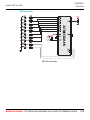
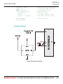
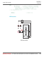
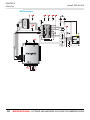
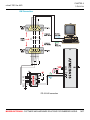
ADC Library . . . . . . . . . . . . . . . . . . . . . . . . . . . . . . . . . . . . . . . . . . . . . . . . . . . 231
ADC_Read . . . . . . . . . . . . . . . . . . . . . . . . . . . . . . . . . . . . . . . . . . . . . . . 231
Library Example . . . . . . . . . . . . . . . . . . . . . . . . . . . . . . . . . . . . . . . . . . . 232
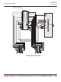
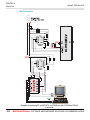
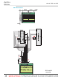
HW Connection . . . . . . . . . . . . . . . . . . . . . . . . . . . . . . . . . . . . . . . . . . . 233
CANSPI Library . . . . . . . . . . . . . . . . . . . . . . . . . . . . . . . . . . . . . . . . . . . . . . . . 234
External dependecies of CANSPI Library . . . . . . . . . . . . . . . . . . . . . . . 235
Library Routines . . . . . . . . . . . . . . . . . . . . . . . . . . . . . . . . . . . . . . . . . . 235
CANSPISetOperationMode . . . . . . . . . . . . . . . . . . . . . . . . . . . . . . . . . . 236
CANSPIGetOperationMode . . . . . . . . . . . . . . . . . . . . . . . . . . . . . . . . . . 236
CANSPIInitialize . . . . . . . . . . . . . . . . . . . . . . . . . . . . . . . . . . . . . . . . . . 237
CANSPISetBaudRate . . . . . . . . . . . . . . . . . . . . . . . . . . . . . . . . . . . . . . 239
CANSPISetMask . . . . . . . . . . . . . . . . . . . . . . . . . . . . . . . . . . . . . . . . . . 240
CANSPISetFilter . . . . . . . . . . . . . . . . . . . . . . . . . . . . . . . . . . . . . . . . . . 241
CANSPIRead . . . . . . . . . . . . . . . . . . . . . . . . . . . . . . . . . . . . . . . . . . . . . 242
CANSPIWrite . . . . . . . . . . . . . . . . . . . . . . . . . . . . . . . . . . . . . . . . . . . . . 243
CANSPI Constants . . . . . . . . . . . . . . . . . . . . . . . . . . . . . . . . . . . . . . . . 244
CANSPI_OP_MODE . . . . . . . . . . . . . . . . . . . . . . . . . . . . . . . . . . . . . . . 244
CANSPI_CONFIG_FLAGS . . . . . . . . . . . . . . . . . . . . . . . . . . . . . . . . . . 244
CANSPI_TX_MSG_FLAGS . . . . . . . . . . . . . . . . . . . . . . . . . . . . . . . . . . 245
CANSPI_RX_MSG_FLAGS . . . . . . . . . . . . . . . . . . . . . . . . . . . . . . . . . 246
CANSPI_MASK . . . . . . . . . . . . . . . . . . . . . . . . . . . . . . . . . . . . . . . . . . . 246
CANSPI_FILTER . . . . . . . . . . . . . . . . . . . . . . . . . . . . . . . . . . . . . . . . . . 247
Library Example . . . . . . . . . . . . . . . . . . . . . . . . . . . . . . . . . . . . . . . . . . . 247
HW Connection . . . . . . . . . . . . . . . . . . . . . . . . . . . . . . . . . . . . . . . . . . . 250
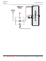
Compact Flash Library . . . . . . . . . . . . . . . . . . . . . . . . . . . . . . . . . . . . . . . . . . . 251
External dependencies of Compact Flash Library . . . . . . . . . . . . . . . . 252
Library Routines . . . . . . . . . . . . . . . . . . . . . . . . . . . . . . . . . . . . . . . . . . 253
Cf_Init . . . . . . . . . . . . . . . . . . . . . . . . . . . . . . . . . . . . . . . . . . . . . . . . . . 254
Cf_Detect . . . . . . . . . . . . . . . . . . . . . . . . . . . . . . . . . . . . . . . . . . . . . . . . 255
Cf_Enable . . . . . . . . . . . . . . . . . . . . . . . . . . . . . . . . . . . . . . . . . . . . . . . 255
Cf_Disable . . . . . . . . . . . . . . . . . . . . . . . . . . . . . . . . . . . . . . . . . . . . . . . 255
MIKROELEKTRONIKA - SOFTWARE AND HARDWARE SOLUTIONS FOR EMBEDDED WORLD
XV
Table of Contents
mikroC PRO for AVR
Cf_Read_Init . . . . . . . . . . . . . . . . . . . . . . . . . . . . . . . . . . . . . . . . . . . . . 256
Cf_Read_Byte . . . . . . . . . . . . . . . . . . . . . . . . . . . . . . . . . . . . . . . . . . . . 256
Cf_Write_Init . . . . . . . . . . . . . . . . . . . . . . . . . . . . . . . . . . . . . . . . . . . . . 257
Cf_Write_Byte . . . . . . . . . . . . . . . . . . . . . . . . . . . . . . . . . . . . . . . . . . . . 257
Cf_Read_Sector . . . . . . . . . . . . . . . . . . . . . . . . . . . . . . . . . . . . . . . . . . 258
Cf_Write_Sector . . . . . . . . . . . . . . . . . . . . . . . . . . . . . . . . . . . . . . . . . . 258
Cf_Fat_Init . . . . . . . . . . . . . . . . . . . . . . . . . . . . . . . . . . . . . . . . . . . . . . . 259
Cf_Fat_QuickFormat . . . . . . . . . . . . . . . . . . . . . . . . . . . . . . . . . . . . . . . 259
Cf_Fat_Assign . . . . . . . . . . . . . . . . . . . . . . . . . . . . . . . . . . . . . . . . . . . . 260
Cf_Fat_Reset . . . . . . . . . . . . . . . . . . . . . . . . . . . . . . . . . . . . . . . . . . . . . 261
Cf_Fat_Read . . . . . . . . . . . . . . . . . . . . . . . . . . . . . . . . . . . . . . . . . . . . . 261
Cf_Fat_Rewrite . . . . . . . . . . . . . . . . . . . . . . . . . . . . . . . . . . . . . . . . . . . 262
Cf_Fat_Append . . . . . . . . . . . . . . . . . . . . . . . . . . . . . . . . . . . . . . . . . . . 262
Cf_Fat_Delete . . . . . . . . . . . . . . . . . . . . . . . . . . . . . . . . . . . . . . . . . . . . 262
Cf_Fat_Write . . . . . . . . . . . . . . . . . . . . . . . . . . . . . . . . . . . . . . . . . . . . . 263
Cf_Fat_Set_File_Date . . . . . . . . . . . . . . . . . . . . . . . . . . . . . . . . . . . . . . 264
Cf_Fat_Get_File_Date . . . . . . . . . . . . . . . . . . . . . . . . . . . . . . . . . . . . . . 265
Cf_Fat_Get_File_Size . . . . . . . . . . . . . . . . . . . . . . . . . . . . . . . . . . . . . . 266
Cf_Fat_Get_Swap_File . . . . . . . . . . . . . . . . . . . . . . . . . . . . . . . . . . . . . 267
Library Example . . . . . . . . . . . . . . . . . . . . . . . . . . . . . . . . . . . . . . . . . . . 269
HW Connection . . . . . . . . . . . . . . . . . . . . . . . . . . . . . . . . . . . . . . . . . . . 274
EEPROM Library . . . . . . . . . . . . . . . . . . . . . . . . . . . . . . . . . . . . . . . . . . . . . . . 275
Library Routines . . . . . . . . . . . . . . . . . . . . . . . . . . . . . . . . . . . . . . . . . . 275
EEPROM_Read . . . . . . . . . . . . . . . . . . . . . . . . . . . . . . . . . . . . . . . . . . . 275
EEPROM_Write . . . . . . . . . . . . . . . . . . . . . . . . . . . . . . . . . . . . . . . . . . . 276
Library Example . . . . . . . . . . . . . . . . . . . . . . . . . . . . . . . . . . . . . . . . . . . 277
Flash Memory Library . . . . . . . . . . . . . . . . . . . . . . . . . . . . . . . . . . . . . . . . . . . 278
Library Routines . . . . . . . . . . . . . . . . . . . . . . . . . . . . . . . . . . . . . . . . . . 278
FLASH_Read_Byte . . . . . . . . . . . . . . . . . . . . . . . . . . . . . . . . . . . . . . . . 278
FLASH_Read_Bytes . . . . . . . . . . . . . . . . . . . . . . . . . . . . . . . . . . . . . . . 279
FLASH_Read_Word . . . . . . . . . . . . . . . . . . . . . . . . . . . . . . . . . . . . . . . 279
FLASH_Read_Words . . . . . . . . . . . . . . . . . . . . . . . . . . . . . . . . . . . . . . 280
Library Example . . . . . . . . . . . . . . . . . . . . . . . . . . . . . . . . . . . . . . . . . . . 280
Graphic LCD Library . . . . . . . . . . . . . . . . . . . . . . . . . . . . . . . . . . . . . . . . . . . . 282
External dependencies of Graphic LCD Library . . . . . . . . . . . . . . . . . . 282
Library Routines . . . . . . . . . . . . . . . . . . . . . . . . . . . . . . . . . . . . . . . . . . 283
XVI
MIKROELEKTRONIKA - SOFTWARE AND HARDWARE SOLUTIONS FOR EMBEDDED WORLD
mikroC PRO for AVR
Table of Contents
Glcd_Init . . . . . . . . . . . . . . . . . . . . . . . . . . . . . . . . . . . . . . . . . . . . . . . . . 284
Glcd_Set_Side . . . . . . . . . . . . . . . . . . . . . . . . . . . . . . . . . . . . . . . . . . . . 285
Glcd_Set_X . . . . . . . . . . . . . . . . . . . . . . . . . . . . . . . . . . . . . . . . . . . . . . 285
Glcd_Set_Page . . . . . . . . . . . . . . . . . . . . . . . . . . . . . . . . . . . . . . . . . . . 286
Glcd_Read_Data . . . . . . . . . . . . . . . . . . . . . . . . . . . . . . . . . . . . . . . . . . 286
Glcd_Write_Data . . . . . . . . . . . . . . . . . . . . . . . . . . . . . . . . . . . . . . . . . . 287
Glcd_Fill . . . . . . . . . . . . . . . . . . . . . . . . . . . . . . . . . . . . . . . . . . . . . . . . . 287
Glcd_Dot . . . . . . . . . . . . . . . . . . . . . . . . . . . . . . . . . . . . . . . . . . . . . . . . 288
Glcd_Line . . . . . . . . . . . . . . . . . . . . . . . . . . . . . . . . . . . . . . . . . . . . . . . . 289
Glcd_V_Line . . . . . . . . . . . . . . . . . . . . . . . . . . . . . . . . . . . . . . . . . . . . . 289
Glcd_H_Line . . . . . . . . . . . . . . . . . . . . . . . . . . . . . . . . . . . . . . . . . . . . . 290
Glcd_Rectangle . . . . . . . . . . . . . . . . . . . . . . . . . . . . . . . . . . . . . . . . . . . 290
Glcd_Box . . . . . . . . . . . . . . . . . . . . . . . . . . . . . . . . . . . . . . . . . . . . . . . . 291
Glcd_Circle . . . . . . . . . . . . . . . . . . . . . . . . . . . . . . . . . . . . . . . . . . . . . . 291
Glcd_Set_Font . . . . . . . . . . . . . . . . . . . . . . . . . . . . . . . . . . . . . . . . . . . . 292
Glcd_Write_Char . . . . . . . . . . . . . . . . . . . . . . . . . . . . . . . . . . . . . . . . . . 293
Glcd_Write_Text . . . . . . . . . . . . . . . . . . . . . . . . . . . . . . . . . . . . . . . . . . 294
Glcd_Image . . . . . . . . . . . . . . . . . . . . . . . . . . . . . . . . . . . . . . . . . . . . . . 295
Library Example . . . . . . . . . . . . . . . . . . . . . . . . . . . . . . . . . . . . . . . . . . . 295
HW Connection . . . . . . . . . . . . . . . . . . . . . . . . . . . . . . . . . . . . . . . . . . . 298
Keypad Library . . . . . . . . . . . . . . . . . . . . . . . . . . . . . . . . . . . . . . . . . . . . . . . . . 299
External dependencies of Keypad Library . . . . . . . . . . . . . . . . . . . . . . . 299
Library Routines . . . . . . . . . . . . . . . . . . . . . . . . . . . . . . . . . . . . . . . . . . 299
Keypad_Init . . . . . . . . . . . . . . . . . . . . . . . . . . . . . . . . . . . . . . . . . . . . . . 300
Keypad_Key_Press . . . . . . . . . . . . . . . . . . . . . . . . . . . . . . . . . . . . . . . . 301
Keypad_Key_Click . . . . . . . . . . . . . . . . . . . . . . . . . . . . . . . . . . . . . . . . . 301
Library Example . . . . . . . . . . . . . . . . . . . . . . . . . . . . . . . . . . . . . . . . . . . 301
HW Connection . . . . . . . . . . . . . . . . . . . . . . . . . . . . . . . . . . . . . . . . . . . 304
Lcd Library . . . . . . . . . . . . . . . . . . . . . . . . . . . . . . . . . . . . . . . . . . . . . . . . . . . . 305
External dependencies of Lcd Library . . . . . . . . . . . . . . . . . . . . . . . . . . 305
Library Routines . . . . . . . . . . . . . . . . . . . . . . . . . . . . . . . . . . . . . . . . . . 306
Lcd_Init . . . . . . . . . . . . . . . . . . . . . . . . . . . . . . . . . . . . . . . . . . . . . . . . . 307
Lcd_Out . . . . . . . . . . . . . . . . . . . . . . . . . . . . . . . . . . . . . . . . . . . . . . . . . 308
Lcd_Out_Cp . . . . . . . . . . . . . . . . . . . . . . . . . . . . . . . . . . . . . . . . . . . . . . 308
Lcd_Chr . . . . . . . . . . . . . . . . . . . . . . . . . . . . . . . . . . . . . . . . . . . . . . . . . 309
Lcd_Chr_Cp . . . . . . . . . . . . . . . . . . . . . . . . . . . . . . . . . . . . . . . . . . . . . . 309
MIKROELEKTRONIKA - SOFTWARE AND HARDWARE SOLUTIONS FOR EMBEDDED WORLD
XVII
Table of Contents
mikroC PRO for AVR
Lcd_Cmd . . . . . . . . . . . . . . . . . . . . . . . . . . . . . . . . . . . . . . . . . . . . . . . . 310
Available Lcd Commands . . . . . . . . . . . . . . . . . . . . . . . . . . . . . . . . . . . 310
Library Example . . . . . . . . . . . . . . . . . . . . . . . . . . . . . . . . . . . . . . . . . . . 311
Manchester Code Library . . . . . . . . . . . . . . . . . . . . . . . . . . . . . . . . . . . . . . . . 313
External dependencies of Manchester Code Library . . . . . . . . . . . . . . 314
Library Routines . . . . . . . . . . . . . . . . . . . . . . . . . . . . . . . . . . . . . . . . . . 314
Man_Receive_Init . . . . . . . . . . . . . . . . . . . . . . . . . . . . . . . . . . . . . . . . . 315
Man_Receive . . . . . . . . . . . . . . . . . . . . . . . . . . . . . . . . . . . . . . . . . . . . . 316
Man_Send_Init . . . . . . . . . . . . . . . . . . . . . . . . . . . . . . . . . . . . . . . . . . . . 316
Man_Send . . . . . . . . . . . . . . . . . . . . . . . . . . . . . . . . . . . . . . . . . . . . . . . 317
Man_Synchro . . . . . . . . . . . . . . . . . . . . . . . . . . . . . . . . . . . . . . . . . . . . . 317
Man_Break . . . . . . . . . . . . . . . . . . . . . . . . . . . . . . . . . . . . . . . . . . . . . . 318
Library Example . . . . . . . . . . . . . . . . . . . . . . . . . . . . . . . . . . . . . . . . . . . 319
Connection Example . . . . . . . . . . . . . . . . . . . . . . . . . . . . . . . . . . . . . . . 321
Multi Media Card Library . . . . . . . . . . . . . . . . . . . . . . . . . . . . . . . . . . . . . . . . . 323
Secure Digital Card . . . . . . . . . . . . . . . . . . . . . . . . . . . . . . . . . . . . . . . . 323
External dependecies of MMC Library . . . . . . . . . . . . . . . . . . . . . . . . . 323
Library Routines . . . . . . . . . . . . . . . . . . . . . . . . . . . . . . . . . . . . . . . . . . 324
Mmc_Init . . . . . . . . . . . . . . . . . . . . . . . . . . . . . . . . . . . . . . . . . . . . . . . . 325
Mmc_Read_Sector . . . . . . . . . . . . . . . . . . . . . . . . . . . . . . . . . . . . . . . . 325
Mmc_Write_Sector . . . . . . . . . . . . . . . . . . . . . . . . . . . . . . . . . . . . . . . . 326
Mmc_Read_Cid . . . . . . . . . . . . . . . . . . . . . . . . . . . . . . . . . . . . . . . . . . . 326
Mmc_Read_Csd . . . . . . . . . . . . . . . . . . . . . . . . . . . . . . . . . . . . . . . . . . 326
Mmc_Fat_Init . . . . . . . . . . . . . . . . . . . . . . . . . . . . . . . . . . . . . . . . . . . . . 327
Mmc_Fat_QuickFormat . . . . . . . . . . . . . . . . . . . . . . . . . . . . . . . . . . . . . 328
Mmc_Fat_Assign . . . . . . . . . . . . . . . . . . . . . . . . . . . . . . . . . . . . . . . . . . 329
Mmc_Fat_Reset . . . . . . . . . . . . . . . . . . . . . . . . . . . . . . . . . . . . . . . . . . 330
Mmc_Fat_Rewrite . . . . . . . . . . . . . . . . . . . . . . . . . . . . . . . . . . . . . . . . . 330
Mmc_Fat_Append . . . . . . . . . . . . . . . . . . . . . . . . . . . . . . . . . . . . . . . . . 330
Mmc_Fat_Read . . . . . . . . . . . . . . . . . . . . . . . . . . . . . . . . . . . . . . . . . . . 331
Mmc_Fat_Delete . . . . . . . . . . . . . . . . . . . . . . . . . . . . . . . . . . . . . . . . . . 331
Mmc_Fat_Write . . . . . . . . . . . . . . . . . . . . . . . . . . . . . . . . . . . . . . . . . . 331
Mmc_Fat_Set_File_Date . . . . . . . . . . . . . . . . . . . . . . . . . . . . . . . . . . . . 332
Mmc_Fat_Get_File_Date . . . . . . . . . . . . . . . . . . . . . . . . . . . . . . . . . . . . 332
Mmc_Fat_Get_File_Size . . . . . . . . . . . . . . . . . . . . . . . . . . . . . . . . . . . . 333
Mmc_Fat_Get_Swap_File . . . . . . . . . . . . . . . . . . . . . . . . . . . . . . . . . . . 334
XVIII
MIKROELEKTRONIKA - SOFTWARE AND HARDWARE SOLUTIONS FOR EMBEDDED WORLD
mikroC PRO for AVR
Table of Contents
Library Example . . . . . . . . . . . . . . . . . . . . . . . . . . . . . . . . . . . . . . . . . . . 335
HW Connection . . . . . . . . . . . . . . . . . . . . . . . . . . . . . . . . . . . . . . . . . . . 346
OneWire Library . . . . . . . . . . . . . . . . . . . . . . . . . . . . . . . . . . . . . . . . . . . . . . . . 347
External dependencies of OneWire Library . . . . . . . . . . . . . . . . . . . . . . 347
Library Routines . . . . . . . . . . . . . . . . . . . . . . . . . . . . . . . . . . . . . . . . . . 348
Ow_Reset . . . . . . . . . . . . . . . . . . . . . . . . . . . . . . . . . . . . . . . . . . . . . . . 348
Ow_Read . . . . . . . . . . . . . . . . . . . . . . . . . . . . . . . . . . . . . . . . . . . . . . . . 349
Ow_Write . . . . . . . . . . . . . . . . . . . . . . . . . . . . . . . . . . . . . . . . . . . . . . . . 349
Library Example . . . . . . . . . . . . . . . . . . . . . . . . . . . . . . . . . . . . . . . . . . . 350
HW Connection . . . . . . . . . . . . . . . . . . . . . . . . . . . . . . . . . . . . . . . . . . . 352
Port Expander Library . . . . . . . . . . . . . . . . . . . . . . . . . . . . . . . . . . . . . . . . . . . 353
External dependencies of Port Expander Library . . . . . . . . . . . . . . . . . 353
Library Routines . . . . . . . . . . . . . . . . . . . . . . . . . . . . . . . . . . . . . . . . . . 353
Expander_Init . . . . . . . . . . . . . . . . . . . . . . . . . . . . . . . . . . . . . . . . . . . . . 354
Expander_Read_Byte . . . . . . . . . . . . . . . . . . . . . . . . . . . . . . . . . . . . . . 355
Expander_Write_Byte . . . . . . . . . . . . . . . . . . . . . . . . . . . . . . . . . . . . . . 355
Expander_Read_PortA . . . . . . . . . . . . . . . . . . . . . . . . . . . . . . . . . . . . . 356
Expander_Read_PortB . . . . . . . . . . . . . . . . . . . . . . . . . . . . . . . . . . . . . 356
Expander_Read_PortAB . . . . . . . . . . . . . . . . . . . . . . . . . . . . . . . . . . . . 357
Expander_Write_PortA . . . . . . . . . . . . . . . . . . . . . . . . . . . . . . . . . . . . . 358
Expander_Write_PortB . . . . . . . . . . . . . . . . . . . . . . . . . . . . . . . . . . . . . 359
Expander_Write_PortAB . . . . . . . . . . . . . . . . . . . . . . . . . . . . . . . . . . . . 360
Expander_Set_DirectionPortA . . . . . . . . . . . . . . . . . . . . . . . . . . . . . . . . 361
Expander_Set_DirectionPortB . . . . . . . . . . . . . . . . . . . . . . . . . . . . . . . . 361
Expander_Set_DirectionPortAB . . . . . . . . . . . . . . . . . . . . . . . . . . . . . . 362
Expander_Set_PullUpsPortA . . . . . . . . . . . . . . . . . . . . . . . . . . . . . . . . . 362
Expander_Set_PullUpsPortB . . . . . . . . . . . . . . . . . . . . . . . . . . . . . . . . . 363
Expander_Set_PullUpsPortAB . . . . . . . . . . . . . . . . . . . . . . . . . . . . . . . 363
Library Example . . . . . . . . . . . . . . . . . . . . . . . . . . . . . . . . . . . . . . . . . . . 364
HW Connection . . . . . . . . . . . . . . . . . . . . . . . . . . . . . . . . . . . . . . . . . . . 365
PS/2 Library . . . . . . . . . . . . . . . . . . . . . . . . . . . . . . . . . . . . . . . . . . . . . . . . . . . 366
External dependencies of PS/2 Library . . . . . . . . . . . . . . . . . . . . . . . . . 366
Library Routines . . . . . . . . . . . . . . . . . . . . . . . . . . . . . . . . . . . . . . . . . . 366
Ps2_Config . . . . . . . . . . . . . . . . . . . . . . . . . . . . . . . . . . . . . . . . . . . . . . 366
Ps2_Key_Read . . . . . . . . . . . . . . . . . . . . . . . . . . . . . . . . . . . . . . . . . . . 366
Ps2_Config . . . . . . . . . . . . . . . . . . . . . . . . . . . . . . . . . . . . . . . . . . . . . . 367
MIKROELEKTRONIKA - SOFTWARE AND HARDWARE SOLUTIONS FOR EMBEDDED WORLD
XIX
Table of Contents
mikroC PRO for AVR
Ps2_Key_Read . . . . . . . . . . . . . . . . . . . . . . . . . . . . . . . . . . . . . . . . . . . 368
Special Function Keys . . . . . . . . . . . . . . . . . . . . . . . . . . . . . . . . . . . . . . 369
Library Example . . . . . . . . . . . . . . . . . . . . . . . . . . . . . . . . . . . . . . . . . . . 370
HW Connection . . . . . . . . . . . . . . . . . . . . . . . . . . . . . . . . . . . . . . . . . . . 371
PWM Library . . . . . . . . . . . . . . . . . . . . . . . . . . . . . . . . . . . . . . . . . . . . . . . . . . 372
Library Routines . . . . . . . . . . . . . . . . . . . . . . . . . . . . . . . . . . . . . . . . . . 372
Predefined constants used in PWM library . . . . . . . . . . . . . . . . . . . . . . 372
PWM_Init . . . . . . . . . . . . . . . . . . . . . . . . . . . . . . . . . . . . . . . . . . . . . . . . 374
PWM_Set_Duty . . . . . . . . . . . . . . . . . . . . . . . . . . . . . . . . . . . . . . . . . . . 376
PWM_Start . . . . . . . . . . . . . . . . . . . . . . . . . . . . . . . . . . . . . . . . . . . . . . 376
PWM_Stop . . . . . . . . . . . . . . . . . . . . . . . . . . . . . . . . . . . . . . . . . . . . . . . 376
PWM1_Init . . . . . . . . . . . . . . . . . . . . . . . . . . . . . . . . . . . . . . . . . . . . . . . 377
PWM1_Set_Duty . . . . . . . . . . . . . . . . . . . . . . . . . . . . . . . . . . . . . . . . . . 379
PWM1_Start . . . . . . . . . . . . . . . . . . . . . . . . . . . . . . . . . . . . . . . . . . . . . 379
PWM1_Stop . . . . . . . . . . . . . . . . . . . . . . . . . . . . . . . . . . . . . . . . . . . . . . 379
Library Example . . . . . . . . . . . . . . . . . . . . . . . . . . . . . . . . . . . . . . . . . . . 380
HW Connection . . . . . . . . . . . . . . . . . . . . . . . . . . . . . . . . . . . . . . . . . . . 381
PWM 16 bit Library . . . . . . . . . . . . . . . . . . . . . . . . . . . . . . . . . . . . . . . . . . . . . 382
Library Routines . . . . . . . . . . . . . . . . . . . . . . . . . . . . . . . . . . . . . . . . . . 382
Predefined constants used in PWM-16bit library . . . . . . . . . . . . . . . . . 382
PWM16bit_Init . . . . . . . . . . . . . . . . . . . . . . . . . . . . . . . . . . . . . . . . . . . . 384
PWM16bit_Change_Duty . . . . . . . . . . . . . . . . . . . . . . . . . . . . . . . . . . . 386
PWM16bit_Start . . . . . . . . . . . . . . . . . . . . . . . . . . . . . . . . . . . . . . . . . . . 387
PWM16bit_Stop . . . . . . . . . . . . . . . . . . . . . . . . . . . . . . . . . . . . . . . . . . . 387
Library Example . . . . . . . . . . . . . . . . . . . . . . . . . . . . . . . . . . . . . . . . . . . 388
HW Connection . . . . . . . . . . . . . . . . . . . . . . . . . . . . . . . . . . . . . . . . . . . 389
RS-485 Library . . . . . . . . . . . . . . . . . . . . . . . . . . . . . . . . . . . . . . . . . . . . . . . . . 390
External dependencies of RS-485 Library . . . . . . . . . . . . . . . . . . . . . . . 390
Library Routines . . . . . . . . . . . . . . . . . . . . . . . . . . . . . . . . . . . . . . . . . . 391
RS485Master_Init . . . . . . . . . . . . . . . . . . . . . . . . . . . . . . . . . . . . . . . . . 391
RS485Master_Receive . . . . . . . . . . . . . . . . . . . . . . . . . . . . . . . . . . . . . 392
RS485Master_Send . . . . . . . . . . . . . . . . . . . . . . . . . . . . . . . . . . . . . . . 393
RS485Slave_Init . . . . . . . . . . . . . . . . . . . . . . . . . . . . . . . . . . . . . . . . . . 394
RS485Slave_Receive . . . . . . . . . . . . . . . . . . . . . . . . . . . . . . . . . . . . . . 395
RS485Slave_Send . . . . . . . . . . . . . . . . . . . . . . . . . . . . . . . . . . . . . . . . 396
Library Example . . . . . . . . . . . . . . . . . . . . . . . . . . . . . . . . . . . . . . . . . . . 396
XX
MIKROELEKTRONIKA - SOFTWARE AND HARDWARE SOLUTIONS FOR EMBEDDED WORLD
mikroC PRO for AVR
Table of Contents
HW Connection . . . . . . . . . . . . . . . . . . . . . . . . . . . . . . . . . . . . . . . . . . . 400
Message format and CRC calculations . . . . . . . . . . . . . . . . . . . . . . . . . 401
Software I˛C Library . . . . . . . . . . . . . . . . . . . . . . . . . . . . . . . . . . . . . . . . 402
External dependecies of Soft_I2C Library . . . . . . . . . . . . . . . . . . . . . . . 402
Library Routines . . . . . . . . . . . . . . . . . . . . . . . . . . . . . . . . . . . . . . . . . . 403
Soft_I2C_Init . . . . . . . . . . . . . . . . . . . . . . . . . . . . . . . . . . . . . . . . . . . . . 403
Soft_I2C_Start . . . . . . . . . . . . . . . . . . . . . . . . . . . . . . . . . . . . . . . . . . . . 404
Soft_I2C_Read . . . . . . . . . . . . . . . . . . . . . . . . . . . . . . . . . . . . . . . . . . . 404
Soft_I2C_Write . . . . . . . . . . . . . . . . . . . . . . . . . . . . . . . . . . . . . . . . . . . 405
Soft_I2C_Stop . . . . . . . . . . . . . . . . . . . . . . . . . . . . . . . . . . . . . . . . . . . . 405
Soft_I2C_Break . . . . . . . . . . . . . . . . . . . . . . . . . . . . . . . . . . . . . . . . . . . 406
Library Example . . . . . . . . . . . . . . . . . . . . . . . . . . . . . . . . . . . . . . . . . . . 407
Software SPI Library . . . . . . . . . . . . . . . . . . . . . . . . . . . . . . . . . . . . . . . . . . . . 410
External dependencies of Software SPI Library . . . . . . . . . . . . . . . . . . 410
Library Routines . . . . . . . . . . . . . . . . . . . . . . . . . . . . . . . . . . . . . . . . . . 411
Soft_SPI_Init . . . . . . . . . . . . . . . . . . . . . . . . . . . . . . . . . . . . . . . . . . . . . 411
Soft_SPI_Read . . . . . . . . . . . . . . . . . . . . . . . . . . . . . . . . . . . . . . . . . . . 412
Soft_SPI_Write . . . . . . . . . . . . . . . . . . . . . . . . . . . . . . . . . . . . . . . . . . . 412
Library Example . . . . . . . . . . . . . . . . . . . . . . . . . . . . . . . . . . . . . . . . . . . 413
Software UART Library . . . . . . . . . . . . . . . . . . . . . . . . . . . . . . . . . . . . . . . . . . 415
External dependencies of Software UART Library . . . . . . . . . . . . . . . . 415
Library Routines . . . . . . . . . . . . . . . . . . . . . . . . . . . . . . . . . . . . . . . . . . 415
Soft_UART_Init . . . . . . . . . . . . . . . . . . . . . . . . . . . . . . . . . . . . . . . . . . . 416
Soft_UART_Read . . . . . . . . . . . . . . . . . . . . . . . . . . . . . . . . . . . . . . . . . 417
Soft_UART_Write . . . . . . . . . . . . . . . . . . . . . . . . . . . . . . . . . . . . . . . . . 418
Soft_UART_Break . . . . . . . . . . . . . . . . . . . . . . . . . . . . . . . . . . . . . . . . . 419
Library Example . . . . . . . . . . . . . . . . . . . . . . . . . . . . . . . . . . . . . . . . . . . 420
Sound Library . . . . . . . . . . . . . . . . . . . . . . . . . . . . . . . . . . . . . . . . . . . . . . . . . 421
External dependencies of Sound Library . . . . . . . . . . . . . . . . . . . . . . . 421
Library Routines . . . . . . . . . . . . . . . . . . . . . . . . . . . . . . . . . . . . . . . . . . 421
Sound_Init . . . . . . . . . . . . . . . . . . . . . . . . . . . . . . . . . . . . . . . . . . . . . . . 422
Sound_Play . . . . . . . . . . . . . . . . . . . . . . . . . . . . . . . . . . . . . . . . . . . . . . 422
Library Example . . . . . . . . . . . . . . . . . . . . . . . . . . . . . . . . . . . . . . . . . . . 423
HW Connection . . . . . . . . . . . . . . . . . . . . . . . . . . . . . . . . . . . . . . . . . . . 425
SPI Library . . . . . . . . . . . . . . . . . . . . . . . . . . . . . . . . . . . . . . . . . . . . . . . . . . . . 426
Library Routines . . . . . . . . . . . . . . . . . . . . . . . . . . . . . . . . . . . . . . . . . . 426
MIKROELEKTRONIKA - SOFTWARE AND HARDWARE SOLUTIONS FOR EMBEDDED WORLD
XXI
Table of Contents
mikroC PRO for AVR
SPI1_Init . . . . . . . . . . . . . . . . . . . . . . . . . . . . . . . . . . . . . . . . . . . . . . . . 426
SPI1_Init_Advanced . . . . . . . . . . . . . . . . . . . . . . . . . . . . . . . . . . . . . . . 427
SPI1_Read . . . . . . . . . . . . . . . . . . . . . . . . . . . . . . . . . . . . . . . . . . . . . . 428
SPI1_Write . . . . . . . . . . . . . . . . . . . . . . . . . . . . . . . . . . . . . . . . . . . . . . . 428
Library Example . . . . . . . . . . . . . . . . . . . . . . . . . . . . . . . . . . . . . . . . . . . 429
HW Connection . . . . . . . . . . . . . . . . . . . . . . . . . . . . . . . . . . . . . . . . . . . 430
SPI Ethernet Library . . . . . . . . . . . . . . . . . . . . . . . . . . . . . . . . . . . . . . . . . . . . 431
External dependencies of SPI Ethernet Library . . . . . . . . . . . . . . . . . . 432
Library Routines . . . . . . . . . . . . . . . . . . . . . . . . . . . . . . . . . . . . . . . . . . 433
SPI_Ethernet_Init . . . . . . . . . . . . . . . . . . . . . . . . . . . . . . . . . . . . . . . . . . 434
SPI_Ethernet_Enable . . . . . . . . . . . . . . . . . . . . . . . . . . . . . . . . . . . . . . 436
SPI_Ethernet_Disable . . . . . . . . . . . . . . . . . . . . . . . . . . . . . . . . . . . . . . 437
SPI_Ethernet_doPacket . . . . . . . . . . . . . . . . . . . . . . . . . . . . . . . . . . . . 438
SPI_Ethernet_putByte . . . . . . . . . . . . . . . . . . . . . . . . . . . . . . . . . . . . . . 439
SPI_Ethernet_putBytes . . . . . . . . . . . . . . . . . . . . . . . . . . . . . . . . . . . . . 439
SPI_Ethernet_putConstBytes . . . . . . . . . . . . . . . . . . . . . . . . . . . . . . . . 440
SPI_Ethernet_putString . . . . . . . . . . . . . . . . . . . . . . . . . . . . . . . . . . . . . 440
SPI_Ethernet_putConstString . . . . . . . . . . . . . . . . . . . . . . . . . . . . . . . . 441
SPI_Ethernet_getByte . . . . . . . . . . . . . . . . . . . . . . . . . . . . . . . . . . . . . . 441
SPI_Ethernet_getBytes . . . . . . . . . . . . . . . . . . . . . . . . . . . . . . . . . . . . . 442
SPI_Ethernet_UserTCP . . . . . . . . . . . . . . . . . . . . . . . . . . . . . . . . . . . . . 443
SPI_Ethernet_UserUDP . . . . . . . . . . . . . . . . . . . . . . . . . . . . . . . . . . . . 444
Library Example . . . . . . . . . . . . . . . . . . . . . . . . . . . . . . . . . . . . . . . . . . . 444
HW Connection . . . . . . . . . . . . . . . . . . . . . . . . . . . . . . . . . . . . . . . . . . . 452
SPI Graphic Lcd Library . . . . . . . . . . . . . . . . . . . . . . . . . . . . . . . . . . . . . . . . . 453
External dependencies of SPI Graphic Lcd Library . . . . . . . . . . . . . . . 453
Library Routines . . . . . . . . . . . . . . . . . . . . . . . . . . . . . . . . . . . . . . . . . . 453
SPI_Glcd_Init . . . . . . . . . . . . . . . . . . . . . . . . . . . . . . . . . . . . . . . . . . . . . 454
SPI_Glcd_Set_Side . . . . . . . . . . . . . . . . . . . . . . . . . . . . . . . . . . . . . . . . 455
SPI_Glcd_Set_Page . . . . . . . . . . . . . . . . . . . . . . . . . . . . . . . . . . . . . . . 455
SPI_Glcd_Set_X . . . . . . . . . . . . . . . . . . . . . . . . . . . . . . . . . . . . . . . . . . 456
SPI_Glcd_Read_Data . . . . . . . . . . . . . . . . . . . . . . . . . . . . . . . . . . . . . . 456
SPI_Glcd_Write_Data . . . . . . . . . . . . . . . . . . . . . . . . . . . . . . . . . . . . . . 457
SPI_Glcd_Fill . . . . . . . . . . . . . . . . . . . . . . . . . . . . . . . . . . . . . . . . . . . . . 457
SPI_Glcd_Dot . . . . . . . . . . . . . . . . . . . . . . . . . . . . . . . . . . . . . . . . . . . . 458
SPI_Glcd_Line . . . . . . . . . . . . . . . . . . . . . . . . . . . . . . . . . . . . . . . . . . . . 458
XXII
MIKROELEKTRONIKA - SOFTWARE AND HARDWARE SOLUTIONS FOR EMBEDDED WORLD
mikroC PRO for AVR
Table of Contents
SPI_Glcd_V_Line . . . . . . . . . . . . . . . . . . . . . . . . . . . . . . . . . . . . . . . . . 459
SPI_Glcd_H_Line . . . . . . . . . . . . . . . . . . . . . . . . . . . . . . . . . . . . . . . . . 459
SPI_Glcd_Rectangle . . . . . . . . . . . . . . . . . . . . . . . . . . . . . . . . . . . . . . . 460
SPI_Glcd_Box . . . . . . . . . . . . . . . . . . . . . . . . . . . . . . . . . . . . . . . . . . . . 460
SPI_Glcd_Circle . . . . . . . . . . . . . . . . . . . . . . . . . . . . . . . . . . . . . . . . . . 461
SPI_Glcd_Set_Font . . . . . . . . . . . . . . . . . . . . . . . . . . . . . . . . . . . . . . . . 462
SPI_Glcd_Write_Char . . . . . . . . . . . . . . . . . . . . . . . . . . . . . . . . . . . . . . 463
SPI_Glcd_Write_Text . . . . . . . . . . . . . . . . . . . . . . . . . . . . . . . . . . . . . . . 464
SPI_Glcd_Image . . . . . . . . . . . . . . . . . . . . . . . . . . . . . . . . . . . . . . . . . . 465
Library Example . . . . . . . . . . . . . . . . . . . . . . . . . . . . . . . . . . . . . . . . . . . 465
HW Connection . . . . . . . . . . . . . . . . . . . . . . . . . . . . . . . . . . . . . . . . . . . 468
SPI Lcd Library . . . . . . . . . . . . . . . . . . . . . . . . . . . . . . . . . . . . . . . . . . . . . . . . 469
External dependencies of SPI Lcd Library . . . . . . . . . . . . . . . . . . . . . . 469
Library Routines . . . . . . . . . . . . . . . . . . . . . . . . . . . . . . . . . . . . . . . . . . 469
SPI_Lcd_Config . . . . . . . . . . . . . . . . . . . . . . . . . . . . . . . . . . . . . . . . . . . 470
SPI_Lcd_Out . . . . . . . . . . . . . . . . . . . . . . . . . . . . . . . . . . . . . . . . . . . . . 471
SPI_Lcd_Out_Cp . . . . . . . . . . . . . . . . . . . . . . . . . . . . . . . . . . . . . . . . . . 471
SPI_Lcd_Chr . . . . . . . . . . . . . . . . . . . . . . . . . . . . . . . . . . . . . . . . . . . . . 472
SPI_Lcd_Chr_Cp . . . . . . . . . . . . . . . . . . . . . . . . . . . . . . . . . . . . . . . . . . 472
SPI_Lcd_Cmd . . . . . . . . . . . . . . . . . . . . . . . . . . . . . . . . . . . . . . . . . . . . 473
Available Lcd Commands . . . . . . . . . . . . . . . . . . . . . . . . . 473
Library Example . . . . . . . . . . . . . . . . . . . . . . . . . . . . . . . . . . . . . . . . . . . 474
HW Connection . . . . . . . . . . . . . . . . . . . . . . . . . . . . . . . . . . . . . . . . . . . 475
SPI Lcd8 (8-bit interface) Library . . . . . . . . . . . . . . . . . . . . . . . . . . . . . . . . . . . 476
External dependencies of SPI Lcd Library . . . . . . . . . . . . . . . . . . . . . . 476
Library Routines . . . . . . . . . . . . . . . . . . . . . . . . . . . . . . . . . . . . . . . . . . 476
SPI_Lcd8_Config . . . . . . . . . . . . . . . . . . . . . . . . . . . . . . . . . . . . . . . . . . 477
SPI_Lcd8_Out . . . . . . . . . . . . . . . . . . . . . . . . . . . . . . . . . . . . . . . . . . . . 478
SPI_Lcd8_Out_Cp . . . . . . . . . . . . . . . . . . . . . . . . . . . . . . . . . . . . . . . . . 478
SPI_Lcd8_Chr . . . . . . . . . . . . . . . . . . . . . . . . . . . . . . . . . . . . . . . . . . . . 479
SPI_Lcd8_Chr_Cp . . . . . . . . . . . . . . . . . . . . . . . . . . . . . . . . . . . . . . . . . 479
SPI_Lcd8_Cmd . . . . . . . . . . . . . . . . . . . . . . . . . . . . . . . . . . . . . . . . . . . 480
Available Lcd Commands . . . . . . . . . . . . . . . . . . . . . . . . . . . . . . . . . . . 480
Library Example . . . . . . . . . . . . . . . . . . . . . . . . . . . . . . . . . . . . . . . . . . . 481
HW Connection . . . . . . . . . . . . . . . . . . . . . . . . . . . . . . . . . . . . . . . . . . . 482
SPI T6963C Graphic Lcd Library . . . . . . . . . . . . . . . . . . . . . . . . . . . . . . . . . . . 483
MIKROELEKTRONIKA - SOFTWARE AND HARDWARE SOLUTIONS FOR EMBEDDED WORLD
XXIII
Table of Contents
mikroC PRO for AVR
External dependencies of SPI T6963C Graphic Lcd Library . . . . . . . . 483
Library Routines . . . . . . . . . . . . . . . . . . . . . . . . . . . . . . . . . . . . . . . . . . 484
SPI_T6963C_Config . . . . . . . . . . . . . . . . . . . . . . . . . . . . . . . . . . . . . . . 485
SPI_T6963C_WriteData . . . . . . . . . . . . . . . . . . . . . . . . . . . . . . . . . . . . 487
SPI_T6963C_WriteCommand . . . . . . . . . . . . . . . . . . . . . . . . . . . . . . . . 487
SPI_T6963C_SetPtr . . . . . . . . . . . . . . . . . . . . . . . . . . . . . . . . . . . . . . . 487
SPI_T6963C_WaitReady . . . . . . . . . . . . . . . . . . . . . . . . . . . . . . . . . . . . 488
SPI_T6963C_Fill . . . . . . . . . . . . . . . . . . . . . . . . . . . . . . . . . . . . . . . . . . 488
SPI_T6963C_Dot . . . . . . . . . . . . . . . . . . . . . . . . . . . . . . . . . . . . . . . . . . 488
SPI_T6963C_Write_Char . . . . . . . . . . . . . . . . . . . . . . . . . . . . . . . . . . . 489
SPI_T6963C_Write_Text . . . . . . . . . . . . . . . . . . . . . . . . . . . . . . . . . . . . 490
SPI_T6963C_Line . . . . . . . . . . . . . . . . . . . . . . . . . . . . . . . . . . . . . . . . . 491
SPI_T6963C_Rectangle . . . . . . . . . . . . . . . . . . . . . . . . . . . . . . . . . . . . 491
SPI_T6963C_Box . . . . . . . . . . . . . . . . . . . . . . . . . . . . . . . . . . . . . . . . . 492
SPI_T6963C_Circle . . . . . . . . . . . . . . . . . . . . . . . . . . . . . . . . . . . . . . . . 492
SPI_T6963C_Image . . . . . . . . . . . . . . . . . . . . . . . . . . . . . . . . . . . . . . . 493
SPI_T6963C_Sprite . . . . . . . . . . . . . . . . . . . . . . . . . . . . . . . . . . . . . . . . 493
SPI_T6963C_Set_Cursor . . . . . . . . . . . . . . . . . . . . . . . . . . . . . . . . . . . 494
SPI_T6963C_ClearBit . . . . . . . . . . . . . . . . . . . . . . . . . . . . . . . . . . . . . . 494
SPI_T6963C_SetBit . . . . . . . . . . . . . . . . . . . . . . . . . . . . . . . . . . . . . . . . 495
SPI_T6963C_NegBit . . . . . . . . . . . . . . . . . . . . . . . . . . . . . . . . . . . . . . . 495
SPI_T6963C_DisplayGrPanel . . . . . . . . . . . . . . . . . . . . . . . . . . . . . . . . 496
SPI_T6963C_DisplayTxtPanel . . . . . . . . . . . . . . . . . . . . . . . . . . . . . . . 496
SPI_T6963C_SetGrPanel . . . . . . . . . . . . . . . . . . . . . . . . . . . . . . . . . . . 496
SPI_T6963C_SetTxtPanel . . . . . . . . . . . . . . . . . . . . . . . . . . . . . . . . . . . 497
SPI_T6963C_PanelFill . . . . . . . . . . . . . . . . . . . . . . . . . . . . . . . . . . . . . 497
SPI_T6963C_GrFill . . . . . . . . . . . . . . . . . . . . . . . . . . . . . . . . . . . . . . . . 497
SPI_T6963C_TxtFill . . . . . . . . . . . . . . . . . . . . . . . . . . . . . . . . . . . . . . . . 498
SPI_T6963C_Cursor_Height . . . . . . . . . . . . . . . . . . . . . . . . . . . . . . . . . 498
SPI_T6963C_Graphics . . . . . . . . . . . . . . . . . . . . . . . . . . . . . . . . . . . . . 498
SPI_T6963C_Text . . . . . . . . . . . . . . . . . . . . . . . . . . . . . . . . . . . . . . . . . 499
SPI_T6963C_Cursor . . . . . . . . . . . . . . . . . . . . . . . . . . . . . . . . . . . . . . . 499
SPI_T6963C_Cursor_Blink . . . . . . . . . . . . . . . . . . . . . . . . . . . . . . . . . . 500
Library Example . . . . . . . . . . . . . . . . . . . . . . . . . . . . . . . . . . . . . . . . . . . 500
HW Connection . . . . . . . . . . . . . . . . . . . . . . . . . . . . . . . . . . . . . . . . . . . 505
T6963C Graphic LCD Library . . . . . . . . . . . . . . . . . . . . . . . . . . . . . . . . . . . . . 506
XXIV
MIKROELEKTRONIKA - SOFTWARE AND HARDWARE SOLUTIONS FOR EMBEDDED WORLD
mikroC PRO for AVR
Table of Contents
External dependencies of T6963C Graphic LCD Library . . . . . . . . . . . 507
Library Routines . . . . . . . . . . . . . . . . . . . . . . . . . . . . . . . . . . . . . . . . . . 508
T6963C_Init . . . . . . . . . . . . . . . . . . . . . . . . . . . . . . . . . . . . . . . . . . . . . . 509
T6963C_WriteData . . . . . . . . . . . . . . . . . . . . . . . . . . . . . . . . . . . . . . . . 510
T6963C_WriteCommand . . . . . . . . . . . . . . . . . . . . . . . . . . . . . . . . . . . . 511
T6963C_SetPtr . . . . . . . . . . . . . . . . . . . . . . . . . . . . . . . . . . . . . . . . . . . 511
T6963C_WaitReady . . . . . . . . . . . . . . . . . . . . . . . . . . . . . . . . . . . . . . . 511
T6963C_Fill . . . . . . . . . . . . . . . . . . . . . . . . . . . . . . . . . . . . . . . . . . . . . . 512
T6963C_Dot . . . . . . . . . . . . . . . . . . . . . . . . . . . . . . . . . . . . . . . . . . . . . 512
T6963C_Write_Char . . . . . . . . . . . . . . . . . . . . . . . . . . . . . . . . . . . . . . . 513
T6963C_Write_Text . . . . . . . . . . . . . . . . . . . . . . . . . . . . . . . . . . . . . . . . 514
T6963C_Line . . . . . . . . . . . . . . . . . . . . . . . . . . . . . . . . . . . . . . . . . . . . . 515
T6963C_Rectangle . . . . . . . . . . . . . . . . . . . . . . . . . . . . . . . . . . . . . . . . 515
T6963C_Box . . . . . . . . . . . . . . . . . . . . . . . . . . . . . . . . . . . . . . . . . . . . . 516
T6963C_Circle . . . . . . . . . . . . . . . . . . . . . . . . . . . . . . . . . . . . . . . . . . . . 516
T6963C_Image . . . . . . . . . . . . . . . . . . . . . . . . . . . . . . . . . . . . . . . . . . . 517
T6963C_Sprite . . . . . . . . . . . . . . . . . . . . . . . . . . . . . . . . . . . . . . . . . . . . 517
T6963C_Set_Cursor . . . . . . . . . . . . . . . . . . . . . . . . . . . . . . . . . . . . . . . 518
T6963C_ClearBit . . . . . . . . . . . . . . . . . . . . . . . . . . . . . . . . . . . . . . . . . . 518
T6963C_SetBit . . . . . . . . . . . . . . . . . . . . . . . . . . . . . . . . . . . . . . . . . . . 519
T6963C_NegBit . . . . . . . . . . . . . . . . . . . . . . . . . . . . . . . . . . . . . . . . . . . 519
T6963C_DisplayGrPanel . . . . . . . . . . . . . . . . . . . . . . . . . . . . . . . . . . . . 520
T6963C_DisplayTxtPanel . . . . . . . . . . . . . . . . . . . . . . . . . . . . . . . . . . . 520
T6963C_SetGrPanel . . . . . . . . . . . . . . . . . . . . . . . . . . . . . . . . . . . . . . . 521
T6963C_SetTxtPanel . . . . . . . . . . . . . . . . . . . . . . . . . . . . . . . . . . . . . . 521
T6963C_PanelFill . . . . . . . . . . . . . . . . . . . . . . . . . . . . . . . . . . . . . . . . . 522
T6963C_GrFill . . . . . . . . . . . . . . . . . . . . . . . . . . . . . . . . . . . . . . . . . . . . 522
T6963C_TxtFill . . . . . . . . . . . . . . . . . . . . . . . . . . . . . . . . . . . . . . . . . . . 522
T6963C_Cursor_Height . . . . . . . . . . . . . . . . . . . . . . . . . . . . . . . . . . . . . 523
T6963C_Graphics . . . . . . . . . . . . . . . . . . . . . . . . . . . . . . . . . . . . . . . . . 523
T6963C_Text . . . . . . . . . . . . . . . . . . . . . . . . . . . . . . . . . . . . . . . . . . . . . 523
T6963C_Cursor . . . . . . . . . . . . . . . . . . . . . . . . . . . . . . . . . . . . . . . . . . . 524
T6963C_Cursor_Blink . . . . . . . . . . . . . . . . . . . . . . . . . . . . . . . . . . . . . . 524
Library Example . . . . . . . . . . . . . . . . . . . . . . . . . . . . . . . . . . . . . . . . . . . 525
HW Connection . . . . . . . . . . . . . . . . . . . . . . . . . . . . . . . . . . . . . . . . . . . 529
TWI Library . . . . . . . . . . . . . . . . . . . . . . . . . . . . . . . . . . . . . . . . . . . . . . . . . . . 530
MIKROELEKTRONIKA - SOFTWARE AND HARDWARE SOLUTIONS FOR EMBEDDED WORLD
XXV
Table of Contents
mikroC PRO for AVR
Library Routines . . . . . . . . . . . . . . . . . . . . . . . . . . . . . . . . . . . . . . . . . . 530
TWI_Init . . . . . . . . . . . . . . . . . . . . . . . . . . . . . . . . . . . . . . . . . . . . . . . . . 530
TWI_Busy . . . . . . . . . . . . . . . . . . . . . . . . . . . . . . . . . . . . . . . . . . . . . . . 531
TWI_Start . . . . . . . . . . . . . . . . . . . . . . . . . . . . . . . . . . . . . . . . . . . . . . . . 531
TWI_Read . . . . . . . . . . . . . . . . . . . . . . . . . . . . . . . . . . . . . . . . . . . . . . . 531
TWI_Write . . . . . . . . . . . . . . . . . . . . . . . . . . . . . . . . . . . . . . . . . . . . . . . 532
TWI_Stop . . . . . . . . . . . . . . . . . . . . . . . . . . . . . . . . . . . . . . . . . . . . . . . . 532
TWI_Status . . . . . . . . . . . . . . . . . . . . . . . . . . . . . . . . . . . . . . . . . . . . . . 532
TWI_Close . . . . . . . . . . . . . . . . . . . . . . . . . . . . . . . . . . . . . . . . . . . . . . . 532
Library Example . . . . . . . . . . . . . . . . . . . . . . . . . . . . . . . . . . . . . . . . . . . 533
HW Connection . . . . . . . . . . . . . . . . . . . . . . . . . . . . . . . . . . . . . . . . . . . 533
UART Library . . . . . . . . . . . . . . . . . . . . . . . . . . . . . . . . . . . . . . . . . . . . . . . . . . 534
Library Routines . . . . . . . . . . . . . . . . . . . . . . . . . . . . . . . . . . . . . . . . . . 534
UARTx_Init . . . . . . . . . . . . . . . . . . . . . . . . . . . . . . . . . . . . . . . . . . . . . . 535
UARTx_Init_Advanced . . . . . . . . . . . . . . . . . . . . . . . . . . . . . . . . . . . . . 536
UARTx_Data_Ready . . . . . . . . . . . . . . . . . . . . . . . . . . . . . . . . . . . . . . . 537
UARTx_Read . . . . . . . . . . . . . . . . . . . . . . . . . . . . . . . . . . . . . . . . . . . . . 537
UARTx_Read_Text . . . . . . . . . . . . . . . . . . . . . . . . . . . . . . . . . . . . . . . . 538
UARTx_Write . . . . . . . . . . . . . . . . . . . . . . . . . . . . . . . . . . . . . . . . . . . . . 539
UARTx_Write_Text . . . . . . . . . . . . . . . . . . . . . . . . . . . . . . . . . . . . . . . . 539
Library Example . . . . . . . . . . . . . . . . . . . . . . . . . . . . . . . . . . . . . . . . . . . 540
HW Connection . . . . . . . . . . . . . . . . . . . . . . . . . . . . . . . . . . . . . . . . . . . 541
ANSI C Ctype Library . . . . . . . . . . . . . . . . . . . . . . . . . . . . . . . . . . . . . . . . . . . 542
Library Functions . . . . . . . . . . . . . . . . . . . . . . . . . . . . . . . . . . . . . . . . . . 542
isalnum . . . . . . . . . . . . . . . . . . . . . . . . . . . . . . . . . . . . . . . . . . . . . . . . . 542
isalpha . . . . . . . . . . . . . . . . . . . . . . . . . . . . . . . . . . . . . . . . . . . . . . . . . . 542
iscntrl . . . . . . . . . . . . . . . . . . . . . . . . . . . . . . . . . . . . . . . . . . . . . . . . . . . 542
isdigit . . . . . . . . . . . . . . . . . . . . . . . . . . . . . . . . . . . . . . . . . . . . . . . . . . . 543
isgraph . . . . . . . . . . . . . . . . . . . . . . . . . . . . . . . . . . . . . . . . . . . . . . . . . . 543
islower . . . . . . . . . . . . . . . . . . . . . . . . . . . . . . . . . . . . . . . . . . . . . . . . . . 543
ispunct . . . . . . . . . . . . . . . . . . . . . . . . . . . . . . . . . . . . . . . . . . . . . . . . . . 543
isspace . . . . . . . . . . . . . . . . . . . . . . . . . . . . . . . . . . . . . . . . . . . . . . . . . . 543
isupper . . . . . . . . . . . . . . . . . . . . . . . . . . . . . . . . . . . . . . . . . . . . . . . . . . 543
isxdigit . . . . . . . . . . . . . . . . . . . . . . . . . . . . . . . . . . . . . . . . . . . . . . . . . . 543
toupper . . . . . . . . . . . . . . . . . . . . . . . . . . . . . . . . . . . . . . . . . . . . . . . . . . 544
tolower . . . . . . . . . . . . . . . . . . . . . . . . . . . . . . . . . . . . . . . . . . . . . . . . . . 544
XXVI
MIKROELEKTRONIKA - SOFTWARE AND HARDWARE SOLUTIONS FOR EMBEDDED WORLD
mikroC PRO for AVR
Table of Contents
ANSI C Math Library . . . . . . . . . . . . . . . . . . . . . . . . . . . . . . . . . . . . . . . . . . . . 545
Library Functions . . . . . . . . . . . . . . . . . . . . . . . . . . . . . . . . . . . . . . . . . . 545
acos . . . . . . . . . . . . . . . . . . . . . . . . . . . . . . . . . . . . . . . . . . . . . . . . . . . . 546
asin . . . . . . . . . . . . . . . . . . . . . . . . . . . . . . . . . . . . . . . . . . . . . . . . . . . . 546
atan . . . . . . . . . . . . . . . . . . . . . . . . . . . . . . . . . . . . . . . . . . . . . . . . . . . . 546
atan2 . . . . . . . . . . . . . . . . . . . . . . . . . . . . . . . . . . . . . . . . . . . . . . . . . . . 546
ceil . . . . . . . . . . . . . . . . . . . . . . . . . . . . . . . . . . . . . . . . . . . . . . . . . . . . . 546
cos . . . . . . . . . . . . . . . . . . . . . . . . . . . . . . . . . . . . . . . . . . . . . . . . . . . . . 546
cosh . . . . . . . . . . . . . . . . . . . . . . . . . . . . . . . . . . . . . . . . . . . . . . . . . . . . 547
eval_poly . . . . . . . . . . . . . . . . . . . . . . . . . . . . . . . . . . . . . . . . . . . . . . . . 547
exp . . . . . . . . . . . . . . . . . . . . . . . . . . . . . . . . . . . . . . . . . . . . . . . . . . . . . 547
fabs . . . . . . . . . . . . . . . . . . . . . . . . . . . . . . . . . . . . . . . . . . . . . . . . . . . . 547
floor . . . . . . . . . . . . . . . . . . . . . . . . . . . . . . . . . . . . . . . . . . . . . . . . . . . . 547
frexp . . . . . . . . . . . . . . . . . . . . . . . . . . . . . . . . . . . . . . . . . . . . . . . . . . . . 547
ldexp . . . . . . . . . . . . . . . . . . . . . . . . . . . . . . . . . . . . . . . . . . . . . . . . . . . 547
log . . . . . . . . . . . . . . . . . . . . . . . . . . . . . . . . . . . . . . . . . . . . . . . . . . . . . 548
log10 . . . . . . . . . . . . . . . . . . . . . . . . . . . . . . . . . . . . . . . . . . . . . . . . . . . 548
modf . . . . . . . . . . . . . . . . . . . . . . . . . . . . . . . . . . . . . . . . . . . . . . . . . . . . 548
pow . . . . . . . . . . . . . . . . . . . . . . . . . . . . . . . . . . . . . . . . . . . . . . . . . . . . 548
sin . . . . . . . . . . . . . . . . . . . . . . . . . . . . . . . . . . . . . . . . . . . . . . . . . . . . . 548
sinh . . . . . . . . . . . . . . . . . . . . . . . . . . . . . . . . . . . . . . . . . . . . . . . . . . . . 548
sqrt . . . . . . . . . . . . . . . . . . . . . . . . . . . . . . . . . . . . . . . . . . . . . . . . . . . . . 548
tan . . . . . . . . . . . . . . . . . . . . . . . . . . . . . . . . . . . . . . . . . . . . . . . . . . . . . 549
tanh . . . . . . . . . . . . . . . . . . . . . . . . . . . . . . . . . . . . . . . . . . . . . . . . . . . . 549
ANSI C Stdlib Library . . . . . . . . . . . . . . . . . . . . . . . . . . . . . . . . . . . . . . . . . . . . 550
Library Functions . . . . . . . . . . . . . . . . . . . . . . . . . . . . . . . . . . . . . . . . . . 550
abs . . . . . . . . . . . . . . . . . . . . . . . . . . . . . . . . . . . . . . . . . . . . . . . . . . . . . 550
atof . . . . . . . . . . . . . . . . . . . . . . . . . . . . . . . . . . . . . . . . . . . . . . . . . . . . . 550
atoi . . . . . . . . . . . . . . . . . . . . . . . . . . . . . . . . . . . . . . . . . . . . . . . . . . . . . 551
atol . . . . . . . . . . . . . . . . . . . . . . . . . . . . . . . . . . . . . . . . . . . . . . . . . . . . . 551
div . . . . . . . . . . . . . . . . . . . . . . . . . . . . . . . . . . . . . . . . . . . . . . . . . . . . . 551
ldiv . . . . . . . . . . . . . . . . . . . . . . . . . . . . . . . . . . . . . . . . . . . . . . . . . . . . . 551
uldiv . . . . . . . . . . . . . . . . . . . . . . . . . . . . . . . . . . . . . . . . . . . . . . . . . . . . 552
labs . . . . . . . . . . . . . . . . . . . . . . . . . . . . . . . . . . . . . . . . . . . . . . . . . . . . 552
max . . . . . . . . . . . . . . . . . . . . . . . . . . . . . . . . . . . . . . . . . . . . . . . . . . . . 552
min . . . . . . . . . . . . . . . . . . . . . . . . . . . . . . . . . . . . . . . . . . . . . . . . . . . . . 552
MIKROELEKTRONIKA - SOFTWARE AND HARDWARE SOLUTIONS FOR EMBEDDED WORLD
XXVII
Table of Contents
mikroC PRO for AVR
rand . . . . . . . . . . . . . . . . . . . . . . . . . . . . . . . . . . . . . . . . . . . . . . . . . . . . 552
srand . . . . . . . . . . . . . . . . . . . . . . . . . . . . . . . . . . . . . . . . . . . . . . . . . . . 552
xtoi . . . . . . . . . . . . . . . . . . . . . . . . . . . . . . . . . . . . . . . . . . . . . . . . . . . . . 553
Div Structures . . . . . . . . . . . . . . . . . . . . . . . . . . . . . . . . . . . . . . . . . . . . 553
ANSI C String Library . . . . . . . . . . . . . . . . . . . . . . . . . . . . . . . . . . . . . . . . . . . 554
Library Functions . . . . . . . . . . . . . . . . . . . . . . . . . . . . . . . . . . . . . . . . . . 554
memchr . . . . . . . . . . . . . . . . . . . . . . . . . . . . . . . . . . . . . . . . . . . . . . . . . 555
memcmp . . . . . . . . . . . . . . . . . . . . . . . . . . . . . . . . . . . . . . . . . . . . . . . . 555
memcpy . . . . . . . . . . . . . . . . . . . . . . . . . . . . . . . . . . . . . . . . . . . . . . . . . 555
memmove . . . . . . . . . . . . . . . . . . . . . . . . . . . . . . . . . . . . . . . . . . . . . . . 555
memset . . . . . . . . . . . . . . . . . . . . . . . . . . . . . . . . . . . . . . . . . . . . . . . . . 555
strcat . . . . . . . . . . . . . . . . . . . . . . . . . . . . . . . . . . . . . . . . . . . . . . . . . . . 556
strchr . . . . . . . . . . . . . . . . . . . . . . . . . . . . . . . . . . . . . . . . . . . . . . . . . . . 556
strcmp . . . . . . . . . . . . . . . . . . . . . . . . . . . . . . . . . . . . . . . . . . . . . . . . . . 556
strcpy . . . . . . . . . . . . . . . . . . . . . . . . . . . . . . . . . . . . . . . . . . . . . . . . . . . 556
strlen . . . . . . . . . . . . . . . . . . . . . . . . . . . . . . . . . . . . . . . . . . . . . . . . . . . 556
strncat . . . . . . . . . . . . . . . . . . . . . . . . . . . . . . . . . . . . . . . . . . . . . . . . . . 557
strncpy . . . . . . . . . . . . . . . . . . . . . . . . . . . . . . . . . . . . . . . . . . . . . . . . . . 557
strspn . . . . . . . . . . . . . . . . . . . . . . . . . . . . . . . . . . . . . . . . . . . . . . . . . . . 557
Strncmp . . . . . . . . . . . . . . . . . . . . . . . . . . . . . . . . . . . . . . . . . . . . . . . . . 557
Strstr . . . . . . . . . . . . . . . . . . . . . . . . . . . . . . . . . . . . . . . . . . . . . . . . . . . 558
Strcspn . . . . . . . . . . . . . . . . . . . . . . . . . . . . . . . . . . . . . . . . . . . . . . . . . . 558
Strpbrk . . . . . . . . . . . . . . . . . . . . . . . . . . . . . . . . . . . . . . . . . . . . . . . . . . 558
Strrchr . . . . . . . . . . . . . . . . . . . . . . . . . . . . . . . . . . . . . . . . . . . . . . . . . . 558
Button Library . . . . . . . . . . . . . . . . . . . . . . . . . . . . . . . . . . . . . . . . . . . . . . . . . 559
External dependecies of Button Library . . . . . . . . . . . . . . . . . . . . . . . . 559
Library Routines . . . . . . . . . . . . . . . . . . . . . . . . . . . . . . . . . . . . . . . . . . 559
Button . . . . . . . . . . . . . . . . . . . . . . . . . . . . . . . . . . . . . . . . . . . . . . . . . . 560
Conversions Library . . . . . . . . . . . . . . . . . . . . . . . . . . . . . . . . . . . . . . . . . . . . . 561
Library Routines . . . . . . . . . . . . . . . . . . . . . . . . . . . . . . . . . . . . . . . . . . 561
ByteToStr . . . . . . . . . . . . . . . . . . . . . . . . . . . . . . . . . . . . . . . . . . . . . . . . 562
ShortToStr . . . . . . . . . . . . . . . . . . . . . . . . . . . . . . . . . . . . . . . . . . . . . . . 562
WordToStr . . . . . . . . . . . . . . . . . . . . . . . . . . . . . . . . . . . . . . . . . . . . . . . 563
IntToStr . . . . . . . . . . . . . . . . . . . . . . . . . . . . . . . . . . . . . . . . . . . . . . . . . 563
LongToStr . . . . . . . . . . . . . . . . . . . . . . . . . . . . . . . . . . . . . . . . . . . . . . . 564
LongWordToStr . . . . . . . . . . . . . . . . . . . . . . . . . . . . . . . . . . . . . . . . . . . 564
MIKROELEKTRONIKA - SOFTWARE AND HARDWARE SOLUTIONS FOR EMBEDDED WORLD
mikroC PRO for AVR
Table of Contents
FloatToStr . . . . . . . . . . . . . . . . . . . . . . . . . . . . . . . . . . . . . . . . . . . . . . . 565
Dec2Bcd . . . . . . . . . . . . . . . . . . . . . . . . . . . . . . . . . . . . . . . . . . . . . . . . 566
Bcd2Dec16 . . . . . . . . . . . . . . . . . . . . . . . . . . . . . . . . . . . . . . . . . . . . . . 566
Dec2Bcd16 . . . . . . . . . . . . . . . . . . . . . . . . . . . . . . . . . . . . . . . . . . . . . . 567
Sprint Library . . . . . . . . . . . . . . . . . . . . . . . . . . . . . . . . . . . . . . . . . . . . . . . . . . 568
Functions . . . . . . . . . . . . . . . . . . . . . . . . . . . . . . . . . . . . . . . . . . . . . . . . 568
sprintf . . . . . . . . . . . . . . . . . . . . . . . . . . . . . . . . . . . . . . . . . . . . . . . . . . . 568
sprintl . . . . . . . . . . . . . . . . . . . . . . . . . . . . . . . . . . . . . . . . . . . . . . . . . . . 571
sprinti . . . . . . . . . . . . . . . . . . . . . . . . . . . . . . . . . . . . . . . . . . . . . . . . . . . 571
Library Example . . . . . . . . . . . . . . . . . . . . . . . . . . . . . . . . . . . . . . . . . . . 572
Time Library . . . . . . . . . . . . . . . . . . . . . . . . . . . . . . . . . . . . . . . . . . . . . . . . . . . 573
Library Routines . . . . . . . . . . . . . . . . . . . . . . . . . . . . . . . . . . . . . . . . . . 573
Time_dateToEpoch . . . . . . . . . . . . . . . . . . . . . . . . . . . . . . . . . . . . . . . . 573
Time_epochToDate . . . . . . . . . . . . . . . . . . . . . . . . . . . . . . . . . . . . . . . . 574
Time_dateDiff . . . . . . . . . . . . . . . . . . . . . . . . . . . . . . . . . . . . . . . . . . . . . 575
Library Example . . . . . . . . . . . . . . . . . . . . . . . . . . . . . . . . . . . . . . . . . . . 576
Trigonometry Library . . . . . . . . . . . . . . . . . . . . . . . . . . . . . . . . . . . . . . . . . . . . 577
Library Routines . . . . . . . . . . . . . . . . . . . . . . . . . . . . . . . . . . . . . . . . . . 577
sinE3 . . . . . . . . . . . . . . . . . . . . . . . . . . . . . . . . . . . . . . . . . . . . . . . . . . . 577
cosE3 . . . . . . . . . . . . . . . . . . . . . . . . . . . . . . . . . . . . . . . . . . . . . . . . . . . 578
MIKROELEKTRONIKA - SOFTWARE AND HARDWARE SOLUTIONS FOR EMBEDDED WORLD
XXIX
Table of Contents
XXX
mikroC PRO for AVR
MIKROELEKTRONIKA - SOFTWARE AND HARDWARE SOLUTIONS FOR EMBEDDED WORLD
CHAPTER
1
Introduction to
mikroC PRO for AVR
The mikroC PRO for AVR is a powerful, feature-rich development tool for AVR microcontrollers. It is designed to provide the programmer with the easiest possible solution to developing applications for embedded systems, without compromising performance or control.
1
CHAPTER 1
mikroC PRO for AVR
Introduction
mikroC PRO for AVR IDE
Features
mikroC PRO for AVR allows you to quickly develop and deploy complex applications:
- Write your C source code using the built-in Code Editor (Code and Parameter Assistants, Code Folding, Syntax Highlighting, Auto Correct, Code Templates, and more.)
- Use included mikroC PRO for AVR libraries to dramatically speed up the development: data acquisition, memory, displays, conversions, communication etc.
- Monitor your program structure, variables, and functions in the Code Explorer.
- Generate commented, human-readable assembly, and standard HEX compatible
with all programmers.
- Inspect program flow and debug executable logic with the integrated Software
Simulator.
2
MIKROELEKTRONIKA - SOFTWARE AND HARDWARE SOLUTIONS FOR EMBEDDED WORLD
mikroC PRO for AVR
CHAPTER 1
Introduction
- Get detailed reports and graphs: RAM and ROM map, code statistics, assembly
listing, calling tree, and more.
- mikroC PRO for AVR provides plenty of examples to expand, develop, and use as
building bricks in your projects. Copy them entirely if you deem fit – that’s why
we included them with the compiler.
Where to Start
- In case that you’re a beginner in programming AVR microcontrollers, read carefully the AVR Specifics chapter. It might give you some useful pointers on AVR
constraints, code portability, and good programming practices.
- If you are experienced in C programming, you will probably want to consult
mikroC PRO for AVR Specifics first. For language issues, you can always refer to
the comprehensive Language Reference. A complete list of included libraries is
available at mikroC PRO for AVR Libraries.
- If you are not very experienced in C programming, don’t panic! mikroC PRO for
AVR provides plenty of examples making it easy for you to go quickly. We suggest
that you first consult Projects and Source Files, and then start browsing the examples that you're the most interested in.
MIKROELEKTRONIKA - SOFTWARE AND HARDWARE SOLUTIONS FOR EMBEDDED WORLD
3
CHAPTER 1
mikroC PRO for AVR
Introduction
MIKROELEKTRONIKA ASSOCIATES LICENSE STATEMENT AND
LIMITED WARRANTY
IMPORTANT - READ CAREFULLY
This license statement and limited warranty constitute a legal agreement (“License
Agreement”) between you (either as an individual or a single entity) and mikroElektronika (“mikroElektronika Associates”) for software product (“Software”) identified
above, including any software, media, and accompanying on-line or printed documentation.
BY INSTALLING, COPYING, OR OTHERWISE USING SOFTWARE, YOU AGREE
TO BE BOUND BY ALL TERMS AND CONDITIONS OF THE LICENSE
AGREEMENT.
Upon your acceptance of the terms and conditions of the License Agreement,
mikroElektronika Associates grants you the right to use Software in a way provided
below.
This Software is owned by mikroElektronika Associates and is protected by copyright law and international copyright treaty. Therefore, you must treat this Software
like any other copyright material (e.g., a book).
You may transfer Software and documentation on a permanent basis provided. You
retain no copies and the recipient agrees to the terms of the License Agreement.
Except as provided in the License Agreement, you may not transfer, rent, lease,
lend, copy, modify, translate, sublicense, time-share or electronically transmit or
receive Software, media or documentation. You acknowledge that Software in the
source code form remains a confidential trade secret of mikroElektronika Associates
and therefore you agree not to modify Software or attempt to reverse engineer,
decompile, or disassemble it, except and only to the extent that such activity is
expressly permitted by applicable law notwithstanding this limitation.
If you have purchased an upgrade version of Software, it constitutes a single product with the mikroElektronika Associates software that you upgraded. You may use
the upgrade version of Software only in accordance with the License Agreement.
4
MIKROELEKTRONIKA - SOFTWARE AND HARDWARE SOLUTIONS FOR EMBEDDED WORLD
mikroC PRO for AVR
CHAPTER 1
Introduction
LIMITED WARRANTY
Respectfully excepting the Redistributables, which are provided “as is”, without warranty of any kind, mikroElektronika Associates warrants that Software, once updated and properly used, will perform substantially in accordance with the accompanying documentation, and Software media will be free from defects in materials and
workmanship, for a period of ninety (90) days from the date of receipt. Any implied
warranties on Software are limited to ninety (90) days.
mikroElektronika Associates’ and its suppliers’ entire liability and your exclusive
remedy shall be, at mikroElektronika Associates’ option, either (a) return of the price
paid, or (b) repair or replacement of Software that does not meet mikroElektronika
Associates’ Limited Warranty and which is returned to mikroElektronika Associates
with a copy of your receipt. DO NOT RETURN ANY PRODUCT UNTIL YOU HAVE
CALLED MIKROELEKTRONIKA ASSOCIATES FIRST AND OBTAINED A RETURN
AUTHORIZATION NUMBER. This Limited Warranty is void if failure of Software has
resulted from an accident, abuse, or misapplication. Any replacement of Software
will be warranted for the rest of the original warranty period or thirty (30) days,
whichever is longer.
TO THE MAXIMUM EXTENT PERMITTED BY APPLICABLE LAW,
MIKROELEKTRONIKA ASSOCIATES AND ITS SUPPLIERS DISCLAIM ALL
OTHER WARRANTIES AND CONDITIONS, EITHER EXPRESSED OR IMPLIED,
INCLUDED, BUT NOT LIMITED TO IMPLIED WARRANTIES OF
MERCHANTABILITY, FITNESS FOR A PARTICULAR PURPOSE, TITLE, AND
NON-INFRINGEMENT, WITH REGARD TO SOFTWARE, AND THE PROVISION
OF OR FAILURE TO PROVIDE SUPPORT SERVICES.
IN NO EVENT SHALL MIKROELEKTRONIKA ASSOCIATES OR ITS SUPPLIERS
BE LIABLE FOR ANY SPECIAL, INCIDENTAL, INDIRECT, OR CONSEQUENTIAL
DAMAGES WHATSOEVER (INCLUDING, WITHOUT LIMITATION, DAMAGES FOR
LOSS OF BUSINESS PROFITS AND BUSINESS INFORMATION, BUSINESS
INTERRUPTION, OR ANY OTHER PECUNIARY LOSS) ARISING OUT OF THE USE
OF OR INABILITY TO USE SOFTWARE PRODUCT OR THE PROVISION OF OR
FAILURE TO PROVIDE SUPPORT SERVICES, EVEN IF MIKROELEKTRONIKA
ASSOCIATES HAS BEEN ADVISED OF THE POSSIBILITY OF SUCH DAMAGES.
IN ANY CASE, MIKROELEKTRONIKA ASSOCIATES’ ENTIRE LIABILITY UNDER
ANY PROVISION OF THIS LICENSE AGREEMENT SHALL BE LIMITED TO THE
AMOUNT ACTUALLY PAID BY YOU FOR SOFTWARE PRODUCT PROVIDED,
HOWEVER, IF YOU HAVE ENTERED INTO A MIKROELEKTRONIKA ASSOCIATES
SUPPORT SERVICES AGREEMENT, MIKROELEKTRONIKA ASSOCIATES’
ENTIRE LIABILITY REGARDING SUPPORT SERVICES SHALL BE GOVERNED BY
THE TERMS OF THAT AGREEMENT.
MIKROELEKTRONIKA - SOFTWARE AND HARDWARE SOLUTIONS FOR EMBEDDED WORLD
5
CHAPTER 1
mikroC PRO for AVR
Introduction
HIGH RISK ACTIVITIES
Software is not fault-tolerant and is not designed, manufactured or intended for use
or resale as on-line control equipment in hazardous environments requiring fail-safe
performance, such as in the operation of nuclear facilities, aircraft navigation or
communication systems, air traffic control, direct life support machines, or weapons
systems, in which the failure of Software could lead directly to death, personal injury,
or severe physical or environmental damage (“High Risk Activities”). mikroElektronika Associates and its suppliers specifically disclaim any expressed or implied warranty of fitness for High Risk Activities.
GENERAL PROVISIONS
This statement may only be modified in writing signed by you and an authorised officer of mikroElektronika Associates. If any provision of this statement is found void
or unenforceable, the remainder will remain valid and enforceable according to its
terms. If any remedy provided is determined to have failed for its essential purpose,
all limitations of liability and exclusions of damages set forth in the Limited Warranty shall remain in effect.
This statement gives you specific legal rights; you may have others, which vary, from
country to country. mikroElektronika Associates reserves all rights not specifically
granted in this statement.
mikroElektronika
Visegradska 1A,
11000 Belgrade,
Europe.
Phone: + 381 11 36 28 830
Fax: +381 11 36 28 831
Web: www.mikroe.com
E-mail: [email protected]
6
MIKROELEKTRONIKA - SOFTWARE AND HARDWARE SOLUTIONS FOR EMBEDDED WORLD
mikroC PRO for AVR
CHAPTER 1
Introduction
TECHNICAL SUPPORT
In case you encounter any problem, you are welcome to our support forums at
www.mikroe.com/forum/. Here, you may also find helpful information, hardware tips,
and practical code snippets. Your comments and suggestions on future development of the mikroC PRO for AVR are always appreciated — feel free to drop a note
or two on our Wishlist.
In our Knowledge Base www.mikroe.com/en/kb/ you can find the answers to Frequently Asked Questions and solutions to known problems. If you can not find the
solution to your problem in Knowledge Base then report it to Support Desk
www.mikroe.com/en/support/. In this way, we can record and track down bugs more
efficiently, which is in our mutual interest. We respond to every bug report and question in a suitable manner, ever improving our technical support.
MIKROELEKTRONIKA - SOFTWARE AND HARDWARE SOLUTIONS FOR EMBEDDED WORLD
7
CHAPTER 1
mikroC PRO for AVR
Introduction
HOW TO REGISTER
The latest version of the mikroC PRO for AVR is always available for downloading
from our website. It is a fully functional software libraries, examples, and comprehensive help included.
The only limitation of the free version is that it cannot generate hex output over 2
KB. Although it might sound restrictive, this margin allows you to develop practical,
working applications with no thinking of demo limit. If you intend to develop really
complex projects in the mikroC PRO for AVR, then you should consider the possibility of purchasing the license key.
Who Gets the License Key
Buyers of the mikroC PRO for AVR are entitled to the license key. After you have
completed the payment procedure, you have an option of registering your mikroC
PRO. In this way you can generate hex output without any limitations.
How to Get License Key
After you have completed the payment procedure, start the program. Select Help › How
to Register from the drop-down menu or click the How To Register Icon
. Fill out
the registration form (figure below), select your distributor, and click the Send button.
8
MIKROELEKTRONIKA - SOFTWARE AND HARDWARE SOLUTIONS FOR EMBEDDED WORLD
mikroC PRO for AVR
CHAPTER 1
Introduction
This will start your e-mail client with message ready for sending. Review the information you have entered, and add the comment if you deem it necessary. Please,
do not modify the subject line.
Upon receiving and verifying your request, we will send the license key to the e-mail
address you specified in the form.
MIKROELEKTRONIKA - SOFTWARE AND HARDWARE SOLUTIONS FOR EMBEDDED WORLD
9
CHAPTER 1
mikroC PRO for AVR
Introduction
After Receving the License Key
The license key comes as a small autoextracting file – just start it anywhere on your
computer in order to activate your copy of compiler and remove the demo limit. You
do not need to restart your computer or install any additional components. Also,
there is no need to run the mikroC PRO for AVR at the time of activation.
Notes:
- The license key is valid until you format your hard disk. In case you need to format
the hard disk, you should request a new activation key.
- Please keep the activation program in a safe place. Every time you upgrade the
compiler you should start this program again in order to reactivate the license.
10
MIKROELEKTRONIKA - SOFTWARE AND HARDWARE SOLUTIONS FOR EMBEDDED WORLD
mikroC PRO for AVR
USER MANUAL
CHAPTER
2
mikroC PRO for
AVR Environment
The mikroC PRO for AVR is an user-friendly and intuitive environment:
11
CHAPTER 2
mikroC PRO for AVR
Environment
IDE OVERVIEW
The mikroC PRO for AVR is an user-friendly and intuitive environment:
- The Code Editor features adjustable Syntax Highlighting, Code Folding, Code
Assistant, Parameters Assistant, Auto Correct for common typos and Code Templates (Auto Complete).
- The Code Explorer (with Keyboard shortcut browser and Quick Help browser) is at
your disposal for easier project management.
- The Project Manager alows multiple project management
- General project settings can be made in the Project Settings window
- Library manager enables simple handling libraries being used in a project
- The Error Window displays all errors detected during compiling and linking.
- The source-level Software Simulator lets you debug executable logic step-by-step
by watching the program flow.
- The New Project Wizard is a fast, reliable, and easy way to create a project.
- Help files are syntax and context sensitive.
12
MIKROELEKTRONIKA - SOFTWARE AND HARDWARE SOLUTIONS FOR EMBEDDED WORLD
mikroC PRO for AVR
CHAPTER 2
Environment
- Like in any modern Windows application, you may customize the layout of mikroC
PRO for AVR to suit your needs best.
- Spell checker underlines identifiers which are unknown to the project. In this way
it helps the programmer to spot potential problems early, much before the project
is compiled.
Spell checker can be disabled by choosing the option in the Preferences dialog (F12).
MAIN MENU OPTIONS
Available Main Menu options are:
- File
- Edit
- View
- Project
- Run
- Tools
- Help
Related topics: Keyboard shortcuts
MIKROELEKTRONIKA - SOFTWARE AND HARDWARE SOLUTIONS FOR EMBEDDED WORLD
13
CHAPTER 2
mikroC PRO for AVR
Environment
FILE MENU OPTIONS
The File menu is the main entry point for manipulation with the source files.
File
Description
Open a new editor window.
Open source file for editing or image file for viewing.
Reopen recently used file.
Save changes for active editor.
Save the active source file with the different name
or change the file type.
Close active source file.
Print Preview.
Exit IDE.
Related topics: Keyboard shortcuts, File Toolbar, Managing Source Files
14
MIKROELEKTRONIKA - SOFTWARE AND HARDWARE SOLUTIONS FOR EMBEDDED WORLD
CHAPTER 2
mikroC PRO for AVR
Environment
EDIT MENU OPTIONS
Edit
Description
Undo last change.
Redo last change.
Cut selected text to clipboard.
Copy selected text to clipboard.
Paste text from clipboard.
Delete selected text.
Select all text in active editor.
Find text in active editor.
MIKROELEKTRONIKA - SOFTWARE AND HARDWARE SOLUTIONS FOR EMBEDDED WORLD
15
CHAPTER 2
mikroC PRO for AVR
Environment
Find next occurence of text in active editor.
Find previous occurence of text in active editor.
Replace text in active editor.
Find text in current file, in all opened files, or in
files from desired folder.
Goto to the desired line in active editor.
Advanced Code Editor options
Advanced>>
Description
Comment selected code or put single line comment if there is no selection.
Uncomment selected code or remove single line comment if there is no selection.
Indent selected code.
Outdent selected code.
Changes selected text case to lowercase.
Changes selected text case to uppercase.
Changes selected text case to titlercase.
16
MIKROELEKTRONIKA - SOFTWARE AND HARDWARE SOLUTIONS FOR EMBEDDED WORLD
mikroC PRO for AVR
CHAPTER 2
Environment
Find Text
Dialog box for searching the document for the specified text. The search is performed in the direction specified. If the string is not found a message is displayed.
Replace Text
Dialog box for searching for a text string in file and replacing it with another text string.
MIKROELEKTRONIKA - SOFTWARE AND HARDWARE SOLUTIONS FOR EMBEDDED WORLD
17
CHAPTER 2
mikroC PRO for AVR
Environment
Find In Files
Dialog box for searching for a text string in current file, all opened files, or in files on a disk.
The string to search for is specified in the Text to find field. If Search in directories
option is selected, The files to search are specified in the Files mask and Path fields.
Go To Line
Dialog box that allows the user to specify the line number at which the cursor should
be positioned.
18
MIKROELEKTRONIKA - SOFTWARE AND HARDWARE SOLUTIONS FOR EMBEDDED WORLD
mikroC PRO for AVR
CHAPTER 2
Environment
Regular expressions
By checking this box, you will be able to advance your search, through Regular
expressions.
Related topics: Keyboard shortcuts, Edit Toolbar, Advanced Edit Toolbar
MIKROELEKTRONIKA - SOFTWARE AND HARDWARE SOLUTIONS FOR EMBEDDED WORLD
19
CHAPTER 2
mikroC PRO for AVR
Environment
VIEW MENU OPTIONS
View
Description
Show/Hide toolbars.
Show/Hide debug windows.
Show/Hide Routine List in active editor.
Show/Hide Project Settings window.
Show/Hide Code Explorer window.
Show/Hide Project Manager window.
Show/Hide Library Manager window.
Show/Hide Bookmarks window.
Show/Hide Error Messages window.
Show/Hide Macro Editor window.
Show Window List window.
20
MIKROELEKTRONIKA - SOFTWARE AND HARDWARE SOLUTIONS FOR EMBEDDED WORLD
CHAPTER 2
mikroC PRO for AVR
Environment
TOOLBARS
File Toolbar
File Toolbar is a standard toolbar with following options:
Icon
Description
Opens a new editor window.
Open source file for editing or image file for viewing.
Save changes for active window.
Save changes in all opened windows.
Close current editor.
Close all editors.
Print Preview.
Edit Toolbar
Edit Toolbar is a standard toolbar with following options:
Icon
Description
Undo last change.
Redo last change.
Cut selected text to clipboard.
Copy selected text to clipboard.
Paste text from clipboard.
MIKROELEKTRONIKA - SOFTWARE AND HARDWARE SOLUTIONS FOR EMBEDDED WORLD
21
CHAPTER 2
mikroC PRO for AVR
Environment
Advanced Edit Toolbar
Advanced Edit Toolbar comes with following options:
Icon
Description
Comment selected code or put single line comment if there is no selection
Uncomment selected code or remove single line comment if there is no selection.
Select text from starting delimiter to ending delimiter.
Go to ending delimiter.
Go to line.
Indent selected code lines.
Outdent selected code lines.
Generate HTML code suitable for publishing current source code on the web.
Find/Replace Toolbar
Find/Replace Toolbar is a standard toolbar with following options:
Icon
Description
Find text in current editor.
Find next occurence.
Find previous occurence.
Replace text.
Find text in files.
22
MIKROELEKTRONIKA - SOFTWARE AND HARDWARE SOLUTIONS FOR EMBEDDED WORLD
CHAPTER 2
mikroC PRO for AVR
Environment
Project Toolbar
Project Toolbar comes with following options:
Icon
Description
Open new project wizard. wizard.
Open Project.
Save Project.
Add existing project to project group.
Remove existing project from project group.
Add File To Project.
Remove File From Project.
Close current project.
Build Toolbar
Build Toolbar comes with following options:
Icon
Description
Build current project.
Build all opened projects.
Build and program active project.
Start programmer and load current HEX file.
Open assembly code in editor.
View statistics for current project.
MIKROELEKTRONIKA - SOFTWARE AND HARDWARE SOLUTIONS FOR EMBEDDED WORLD
23
CHAPTER 2
mikroC PRO for AVR
Environment
Debugger
Debugger Toolbar comes with following options:
Icon
Description
Start Software Simulator.
Run/Pause debugger.
Stop debugger.
Step into.
Step over.
Step out.
Run to cursor.
Toggle breakpoint.
Toggle breakpoints.
Clear breakpoints.
View watch window
View stopwatch window
24
MIKROELEKTRONIKA - SOFTWARE AND HARDWARE SOLUTIONS FOR EMBEDDED WORLD
CHAPTER 2
mikroC PRO for AVR
Environment
Styles Toolbar
Styles toolbar allows you to easily customize your workspace.
Tools Toolbar
Tools Toolbar comes with following default options:
Icon
Description
Run USART Terminal
EEPROM
ASCII Chart
Seven segment decoder tool.
The Tools toolbar can easily be customized by adding new tools in Options(F12)
window.
Related topics: Keyboard shortcuts, Integrated Tools, Debugger Windows
MIKROELEKTRONIKA - SOFTWARE AND HARDWARE SOLUTIONS FOR EMBEDDED WORLD
25
CHAPTER 2
mikroC PRO for AVR
Environment
PROJECT MENU OPTIONS
26
MIKROELEKTRONIKA - SOFTWARE AND HARDWARE SOLUTIONS FOR EMBEDDED WORLD
CHAPTER 2
mikroC PRO for AVR
Environment
Project
Description
Build active project.
Build all projects.
Build and program active project.
View Assembly.
Edit search paths.
Clean Project Folder
Add file to project.
Remove file from project.
Open New Project Wizard
Open existing project.
Save current project.
Open project group.
Close project group.
Save active project file with the different name.
Open recently used project.
Close active project.
Related topics: Keyboard shortcuts, Project Toolbar, Creating New Project, Project
Manager, Project Settings
MIKROELEKTRONIKA - SOFTWARE AND HARDWARE SOLUTIONS FOR EMBEDDED WORLD
27
CHAPTER 2
mikroC PRO for AVR
Environment
RUN MENU OPTIONS
28
MIKROELEKTRONIKA - SOFTWARE AND HARDWARE SOLUTIONS FOR EMBEDDED WORLD
CHAPTER 2
mikroC PRO for AVR
Environment
Run
Description
Start Software Simulator.
Stop debugger.
Pause Debugger.
Step Into.
Step Over.
Step Out.
Jump to interrupt in current project.
Toggle Breakpoint.
Breakpoints.
Clear Breakpoints.
Show/Hide Watch Window
Show/Hide Stopwatch Window
Toggle between C source and disassembly.
Related topics: Keyboard shortcuts, Debug Toolbar
MIKROELEKTRONIKA - SOFTWARE AND HARDWARE SOLUTIONS FOR EMBEDDED WORLD
29
CHAPTER 2
mikroC PRO for AVR
Environment
TOOLS MENU OPTIONS
Tools
Description
Run mikroElektronika Programmer
Run USART Terminal
Run EEPROM Editor
Run ASCII Chart
Run 7 Segment Display Decoder
Generate HTML code suitable for publishing
source code on the web.
Generate your own custom LCD characters
Generate bitmap pictures for GLCD
UDP communication terminal.
Open Options window
Related topics: Keyboard shortcuts, Tools Toolbar
30
MIKROELEKTRONIKA - SOFTWARE AND HARDWARE SOLUTIONS FOR EMBEDDED WORLD
CHAPTER 2
mikroC PRO for AVR
Environment
HELP MENU OPTIONS
Help
Description
Îpen Help File.
Quick Help.
Check if new compiler version is available.
Open mikroElektronika Support Forums in a
default browser.
Open mikroElektronika Web Page in a default
browser.
Information on how to register.
Open About window.
Related topics: Keyboard shortcuts
MIKROELEKTRONIKA - SOFTWARE AND HARDWARE SOLUTIONS FOR EMBEDDED WORLD
31
CHAPTER 2
mikroC PRO for AVR
Environment
KEYBOARD SHORTCUTS
Below is a complete list of keyboard shortcuts available in mikroC PRO for AVR IDE.
You can also view keyboard shortcuts in the Code Explorer window, tab Keyboard.
IDE Shortcuts
F1
Help
Ctrl+N
New Unit
Ctrl+O
Open
Ctrl+Shift+O
Open Project
Ctrl+Shift+N
Open New Project
Ctrl+K
Close Project
Ctrl+F9
Compile
Shift+F9
Compile All
Ctrl+F11
Compile and Program
Shift+F4
View breakpoints
Ctrl+Shift+F5
Clear breakpoints
F11
Start AVRFlash Programmer
F12
Preferences
Basic Editor Shortcuts
32
F3
Find, Find Next
Shift+F3
Find Previous
Alt+F3
Grep Search, Find in Files
Ctrl+A
Grep Search, Find in Files
Ctrl+C
Copy
Ctrl+F
Find
Ctrl+R
Replace
Ctrl+P
Print
Ctrl+S
Save unit
Ctrl+Shift+S
Save All
Ctrl+V
Paste
MIKROELEKTRONIKA - SOFTWARE AND HARDWARE SOLUTIONS FOR EMBEDDED WORLD
CHAPTER 2
mikroC PRO for AVR
Environment
Ctrl+X
Cut
Ctrl+Y
Delete entire line
Ctrl+Z
Undo
Ctrl+Shift+Z
Redo
Advanced Editor Shortcuts
Ctrl+Space
Code Assistant
Ctrl+Shift+Space
Parameters Assistant
Ctrl+D
Find declaration
Ctrl+E
Incremental Search
Ctrl+L
Routine List
Ctrl+G
Goto line
Ctrl+J
Insert Code Template
Ctrl+Shift+.
Comment Code
Ctrl+Shift+,
Uncomment Code
Ctrl+number
Goto bookmark
Ctrl+Shift+number Set bookmark
Ctrl+Shift+I
Indent selection
Ctrl+Shift+U
Unindent selection
TAB
Indent selection
Shift+TAB
Unindent selection
Alt+Select
Select columns
Ctrl+Alt+Select
Select columns
Ctrl+Alt+L
Convert selection to lowercase
Ctrl+Alt+U
Convert selection to uppercase
Ctrl+Alt+T
Convert to Titlecase
MIKROELEKTRONIKA - SOFTWARE AND HARDWARE SOLUTIONS FOR EMBEDDED WORLD
33
CHAPTER 2
mikroC PRO for AVR
Environment
Software Simulator Shortcuts
34
F2
Jump To Interrupt
F4
Run to Cursor
F5
Toggle Breakpoint
F6
Run/Pause Debugger
F7
Step into
F8
Step over
F9
Debug
Ctrl+F2
Reset
Ctrl+F5
Add to Watch List
Ctrl+F8
Step out
Alt+D
Dissasembly view
Shift+F5
Open Watch Window
MIKROELEKTRONIKA - SOFTWARE AND HARDWARE SOLUTIONS FOR EMBEDDED WORLD
mikroC PRO for AVR
CHAPTER 2
Environment
MIKROC PRO FOR AVR IDE
IDE Overview
The mikroC PRO for AVR is an user-friendly and intuitive environment:
- The Code Editor features adjustable Syntax Highlighting, Code Folding, Code
Assistant, Parameters Assistant, Auto Correct for common typos and Code Templates (Auto Complete).
- The Code Explorer (with Keyboard shortcut browser and Quick Help browser) is at
your disposal for easier project management.
- The Project Manager alows multiple project management.
- General project settings can be made in the Project Settings window.
- Library manager enables simple handling libraries being used in a project.
- The Error Window displays all errors detected during compiling and linking.
- The source-level Software Simulator lets you debug executable logic step-by-step
by watching the program flow.
MIKROELEKTRONIKA - SOFTWARE AND HARDWARE SOLUTIONS FOR EMBEDDED WORLD
35
CHAPTER 2
Environment
mikroC PRO for AVR
- The New Project Wizard is a fast, reliable, and easy way to create a project.
- Help files are syntax and context sensitive.
- Like in any modern Windows application, you may customize the layout of mikroC
PRO for AVR to suit your needs best.
- Spell checker underlines identifiers which are unknown to the project. In this way
it helps the programmer to spot potential problems early, much before the project
is compiled.
Spell checker can be disabled by choosing the option in the Preferences dialog (F12).
36
MIKROELEKTRONIKA - SOFTWARE AND HARDWARE SOLUTIONS FOR EMBEDDED WORLD
mikroC PRO for AVR
CHAPTER 2
Environment
CUSTOMIZING IDE LAYOUT
Docking Windows
You can increase the viewing and editing space for code, depending on how you
arrange the windows in the IDE.
Step 1: Click the window you want to dock, to give it focus.
Step 2: Drag the tool window from its current location. A guide diamond appears.
The four arrows of the diamond point towards the four edges of the IDE.
MIKROELEKTRONIKA - SOFTWARE AND HARDWARE SOLUTIONS FOR EMBEDDED WORLD
37
CHAPTER 2
mikroC PRO for AVR
Environment
Step 3: Move the pointer over the corresponding portion of the guide diamond. An
outline of the window appears in the designated area.
Step 4: To dock the window in the position indicated, release the mouse button.
Tip: To move a dockable window without snapping it into place, press CTRL while
dragging it.
Saving Layout
Once you have a window layout that you like, you can save the layout by typing the
name for the layout and pressing the Save Layout Icon
.
To set the layout select the desired layout from the layout drop-down list and click
the Set Layout Icon
.
To remove the layout from the drop-down list, select the desired layout from the list
and click the Delete Layout Icon
38
.
MIKROELEKTRONIKA - SOFTWARE AND HARDWARE SOLUTIONS FOR EMBEDDED WORLD
CHAPTER 2
mikroC PRO for AVR
Environment
Auto Hide
Auto Hide enables you to see more of your code at one time by minimizing tool windows along the edges of the IDE when not in use.
-Click the window you want to keep visible to give it focus.
-Click the Pushpin Icon
on the title bar of the window.
When an auto-hidden window loses focus, it automatically slides back to its tab on
the edge of the IDE. While a window is auto-hidden, its name and icon are visible
on a tab at the edge of the IDE. To display an auto-hidden window, move your pointer over the tab. The window slides back into view and is ready for use.
MIKROELEKTRONIKA - SOFTWARE AND HARDWARE SOLUTIONS FOR EMBEDDED WORLD
39
CHAPTER 2
mikroC PRO for AVR
Environment
ADVANCED CODE EDITOR
The Code Editor is advanced text editor fashioned to satisfy needs of professionals.
General code editing is the same as working with any standard text-editor, including
familiar Copy, Paste and Undo actions, common for Windows environment.
Advanced Editor Features
- Adjustable Syntax Highlighting
- Code Assistant
- Code Folding
- Parameter Assistant
- Code Templates (Auto Complete)
- Auto Correct for common typos
- Spell Checker
- Bookmarks and Goto Line
- Comment / Uncomment
You can configure the Syntax Highlighting, Code Templates and Auto Correct from
the Editor Settings dialog. To access the Settings, click Tools › Options from the
drop-down menu, click the Show Options Icon
40
or press F12 key.
MIKROELEKTRONIKA - SOFTWARE AND HARDWARE SOLUTIONS FOR EMBEDDED WORLD
mikroC PRO for AVR
CHAPTER 2
Environment
Code Assistant
If you type the first few letters of a word and then press Ctrl+Space, all valid identifiers matching the letters you have typed will be prompted in a floating panel (see
the image below). Now you can keep typing to narrow the choice, or you can select
one from the list using the keyboard arrows and Enter.
MIKROELEKTRONIKA - SOFTWARE AND HARDWARE SOLUTIONS FOR EMBEDDED WORLD
41
CHAPTER 2
mikroC PRO for AVR
Environment
Code Folding
Code folding is IDE feature which allows users to selectively hide and display sections of a source file. In this way it is easier to manage large regions of code within
one window, while still viewing only those subsections of the code that are relevant
during a particular editing session.
While typing, the code folding symbols ( and ) appear automatically. Use the
folding symbols to hide/unhide the code subsections.
If you place a mouse cursor over the tooltip box, the collapsed text will be shown in
a tooltip style box.
42
MIKROELEKTRONIKA - SOFTWARE AND HARDWARE SOLUTIONS FOR EMBEDDED WORLD
CHAPTER 2
mikroC PRO for AVR
Environment
Parameter Assistant
The Parameter Assistant will be automatically invoked when you open parenthesis
“(” or press Shift+Ctrl+Space. If the name of a valid function precedes the parenthesis, then the expected parameters will be displayed in a floating panel. As you type
the actual parameter, the next expected parameter will become bold.
Code Templates (Auto Complete)
You can insert the Code Template by typing the name of the template (for instance,
whiles), then press Ctrl+J and the Code Editor will automatically generate a code.
You can add your own templates to the list. Select Tools › Options from the drop-down
menu, or click the Show Options Icon
and then select the Auto Complete Tab.
Here you can enter the appropriate keyword, description and code of your template.
Autocomplete macros can retreive system and project information:
-
%DATE% - current system date
%TIME% - current system time
%DEVICE% - device(MCU) name as specified in project settings
%DEVICE_CLOCK% - clock as specified in project settings
%COMPILER% - current compiler version
These macros can be used in template code, see template ptemplate provided with
mikroC PRO for AVR installation.
Auto Correct
The Auto Correct feature corrects common typing mistakes. To access the list of recognized typos, select Tools › Options from the drop-down
menu, or click the Show Options Icon
and then select the
Auto Correct Tab. You can also add your own preferences to the list.
MIKROELEKTRONIKA - SOFTWARE AND HARDWARE SOLUTIONS FOR EMBEDDED WORLD
43
CHAPTER 2
mikroC PRO for AVR
Environment
Also, the Code Editor has a feature to comment or uncomment the selected code
by simple click of a mouse, using the Comment Icon
and Uncomment Icon
from the Code Toolbar.
Spell Checker
The Spell Checker underlines unknown objects in the code, so they can be easily
noticed and corrected before compiling your project.
Select Tools › Options from the drop-down menu, or click the Show Options Icon
and then select the Spell Checker Tab.
Bookmarks
Bookmarks make navigation through a large code easier. To set a bookmark, use
Ctrl+Shift+number. To jump to a bookmark, use Ctrl+number.
Goto Line
The Goto Line option makes navigation through a large code easier. Use the shortcut Ctrl+G to activate this option.
Comment / Uncomment
Also, the Code Editor has a feature to comment or uncomment the selected code
by simple click of a mouse, using the Comment Icon
and Uncomment Icon
from the Code Toolbar.
44
MIKROELEKTRONIKA - SOFTWARE AND HARDWARE SOLUTIONS FOR EMBEDDED WORLD
CHAPTER 2
mikroC PRO for AVR
Environment
CODE EXPLORER
The Code Explorer gives clear view of each item declared inside the source code.
You can jump to a declaration of any item by right clicking it. Also, besides the list of
defined and declared objects, code explorer displays message about first error and
it's location in code.
Following options are available in the Code Explorer:
Icon
Description
Expand/Collapse all nodes in tree.
Locate declaration in code.
MIKROELEKTRONIKA - SOFTWARE AND HARDWARE SOLUTIONS FOR EMBEDDED WORLD
45
CHAPTER 2
mikroC PRO for AVR
Environment
ROUTINE LIST
Routine list diplays list of routines, and enables filtering routines by name. Routine
list window can be accessed by pressing Ctrl+L.
You can jump to a desired routine by double clicking on it.
46
MIKROELEKTRONIKA - SOFTWARE AND HARDWARE SOLUTIONS FOR EMBEDDED WORLD
mikroC PRO for AVR
CHAPTER 2
Environment
PROJECT MANAGER
Project Manager is IDE feature which allows users to manage multiple projects.
Several projects which together make project group may be open at the same time.
Only one of them may be active at the moment.
Setting project in active mode is performed by double click on the desired project
in the Project Manager.
Following options are available in the Project Manager:
MIKROELEKTRONIKA - SOFTWARE AND HARDWARE SOLUTIONS FOR EMBEDDED WORLD
47
CHAPTER 2
mikroC PRO for AVR
Environment
Icon
Description
Save project Group.
Open project group.
Close the active project.
Close project group.
Add project to the project group.
Remove project from the project group.
Add file to the active project.
Remove selected file from the project.
Build the active project.
Run mikroElektronika's Flash programmer.
For details about adding and removing files from project see Add/Remove Files from
Project.
Related topics: Project Settings, Project Menu Options, File Menu Options, Project
Toolbar, Build Toolbar, Add/Remove Files from Project
48
MIKROELEKTRONIKA - SOFTWARE AND HARDWARE SOLUTIONS FOR EMBEDDED WORLD
CHAPTER 2
mikroC PRO for AVR
Environment
PROJECT SETTINGS WINDOW
Following options are available in the Project Settings Window:
- Device - select the appropriate device from the device drop-down list.
- Oscillator - enter the oscillator frequency value.
MIKROELEKTRONIKA - SOFTWARE AND HARDWARE SOLUTIONS FOR EMBEDDED WORLD
49
CHAPTER 2
mikroC PRO for AVR
Environment
LIBRARY MANAGER
Library Manager enables simple handling
libraries being used in a project. Library Manager window lists all libraries (extencion .mcl)
which are instantly stored in the compiler Uses
folder. The desirable library is added to the project by selecting check box next to the library
name.
In order to have all library functions accessible,
simply press the button Check All
and all
libraries will be selected. In case none library is
needed in a project, press the button Clear All
and all libraries will be cleared from the
project.
Only the selected libraries will be linked.
50
MIKROELEKTRONIKA - SOFTWARE AND HARDWARE SOLUTIONS FOR EMBEDDED WORLD
CHAPTER 2
mikroC PRO for AVR
Icon
Environment
Description
Refresh Library by scanning files in "Uses" folder.Useful when new
libraries are added by copying files to "Uses" folder.
Rebuild all available libraries. Useful when library sources are available and need refreshing.
Include all available libraries in current project.
No libraries from the list will be included in current project.
Restore library to the state just before last project saving.
Related topics: mikroC PRO for AVR Libraries, Creating New Library
MIKROELEKTRONIKA - SOFTWARE AND HARDWARE SOLUTIONS FOR EMBEDDED WORLD
51
CHAPTER 2
mikroC PRO for AVR
Environment
ERROR WINDOW
In case that errors were encountered during compiling, the compiler will report them
and won’t generate a hex file. The Error Window will be prompted at the bottom of
the main window by default.
The Error Window is located under message tab, and displays location and type of
errors the compiler has encountered. The compiler also reports warnings, but these
do not affect the output; only errors can interefere with the generation of hex.
Double click the message line in the Error Window to highlight the line where the
error was encountered.
Related topics: Error Messages
52
MIKROELEKTRONIKA - SOFTWARE AND HARDWARE SOLUTIONS FOR EMBEDDED WORLD
CHAPTER 2
mikroC PRO for AVR
Environment
STATISTICS
After successful compilation, you can review statistics of your code. Click the Statistics Icon
.
Memory Usage Windows
Provides overview of RAM and ROM usage in the form of histogram.
RAM Memory
Rx Memory Space
Displays Rx memory space usage in form of histogram.
MIKROELEKTRONIKA - SOFTWARE AND HARDWARE SOLUTIONS FOR EMBEDDED WORLD
53
CHAPTER 2
mikroC PRO for AVR
Environment
Data Memory Space
Displays Data memory space usage in form of histogram.
Special Function Registers
Summarizes all Special Function Registers and their addresses.
54
MIKROELEKTRONIKA - SOFTWARE AND HARDWARE SOLUTIONS FOR EMBEDDED WORLD
mikroC PRO for AVR
CHAPTER 2
Environment
General Purpose Registers
Summarizes all General Purpose Registers and their addresses. Also displays symbolic names of variables and their addresses.
ROM Memory
ROM Memory Usage
Displays ROM memory usage in form of histogram.
MIKROELEKTRONIKA - SOFTWARE AND HARDWARE SOLUTIONS FOR EMBEDDED WORLD
55
CHAPTER 2
mikroC PRO for AVR
Environment
ROM Memory Allocation
Displays ROM memory allocation.
Procedures Windows
Provides overview procedures locations and sizes.
56
MIKROELEKTRONIKA - SOFTWARE AND HARDWARE SOLUTIONS FOR EMBEDDED WORLD
mikroC PRO for AVR
CHAPTER 2
Environment
Procedures Size Window
Displays size of each procedure.
Procedures Locations Window
Displays how functions are distributed in microcontroller’s memory.
MIKROELEKTRONIKA - SOFTWARE AND HARDWARE SOLUTIONS FOR EMBEDDED WORLD
57
CHAPTER 2
mikroC PRO for AVR
Environment
HTML Window
Display statistics in default web browser.
58
MIKROELEKTRONIKA - SOFTWARE AND HARDWARE SOLUTIONS FOR EMBEDDED WORLD
CHAPTER 2
mikroC PRO for AVR
Environment
MACRO EDITOR
A macro is a series of keystrokes that have been 'recorded' in the order performed.
A macro allows you to 'record' a series of keystrokes and then 'playback', or repeat,
the recorded keystrokes.
The Macro offers the following commands:
Icon
Description
Starts 'recording' keystrokes for later playback.
Stops capturing keystrokesthat was started when the Start Recordig
command was selected.
Allows a macro that has been recorded to be replayed.
New macro.
Delete macro.
Related topics: Advanced Code Editor, Code Templates
MIKROELEKTRONIKA - SOFTWARE AND HARDWARE SOLUTIONS FOR EMBEDDED WORLD
59
CHAPTER 2
mikroC PRO for AVR
Environment
INTEGRATED TOOLS
USART Terminal
The mikroC PRO for AVR includes the USART communication terminal for RS232
communication. You can launch it from the drop-down menu Tools › USART Terminal or by clicking the USART Terminal Icon
60
from Tools toolbar.
MIKROELEKTRONIKA - SOFTWARE AND HARDWARE SOLUTIONS FOR EMBEDDED WORLD
CHAPTER 2
mikroC PRO for AVR
Environment
ASCII Chart
The ASCII Chart is a handy tool, particularly useful when working with LCD display.
You can launch it from the drop-down menu Tools › ASCII chart or by clicking the
View ASCII Chart Icon
from Tools toolbar.
MIKROELEKTRONIKA - SOFTWARE AND HARDWARE SOLUTIONS FOR EMBEDDED WORLD
61
CHAPTER 2
mikroC PRO for AVR
Environment
EEPROM Editor
The EEPROM Editor is used for manipulating MCU's EEPROM memory. You can
launch it from the drop-down menu Tools › EEPROM Editor. When Use this
EEPROM definition is checked compiler will generate Intel hex file
project_name.ihex that contains data from EEPROM editor.
When you run mikroElektronika programmer software from mikroC PRO for AVR
IDE - project_name.hex file will be loaded automatically while ihex file must be
loaded manually.
62
MIKROELEKTRONIKA - SOFTWARE AND HARDWARE SOLUTIONS FOR EMBEDDED WORLD
CHAPTER 2
mikroC PRO for AVR
Environment
7 Segment Display Decoder
The 7 Segment Display Decoder is a convenient visual panel which returns decimal/hex value for any viable combination you would like to display on 7seg. Click on
the parts of 7 segment image to get the requested value in the edit boxes. You can
launch it from the drop-down menu Tools › 7 Segment Decoderor by clicking the
Seven Segment Icon
from Tools toolbar.
MIKROELEKTRONIKA - SOFTWARE AND HARDWARE SOLUTIONS FOR EMBEDDED WORLD
63
CHAPTER 2
mikroC PRO for AVR
Environment
UDP Terminal
The mikroC PRO for AVR includes the UDP Terminal. You can launch it from the
drop-down menu Tools › UDP Terminal.
64
MIKROELEKTRONIKA - SOFTWARE AND HARDWARE SOLUTIONS FOR EMBEDDED WORLD
mikroC PRO for AVR
CHAPTER 2
Environment
Graphic LCD Bitmap Editor
The mikroC PRO for AVR includes the Graphic LCD Bitmap Editor. Output is the
mikroC PRO for AVR compatible code. You can launch it from the drop-down menu
Tools › GLCD Bitmap Editor.
MIKROELEKTRONIKA - SOFTWARE AND HARDWARE SOLUTIONS FOR EMBEDDED WORLD
65
CHAPTER 2
mikroC PRO for AVR
Environment
LCD Custom Character
mikroC PRO for AVR includes the LCD Custom Character. Output is mikroC PRO
for AVR compatible code. You can launch it from the drop-down menu Tools › LCD
Custom Character.
66
MIKROELEKTRONIKA - SOFTWARE AND HARDWARE SOLUTIONS FOR EMBEDDED WORLD
mikroC PRO for AVR
CHAPTER 2
Environment
OPTIONS
Options menu consists of three tabs: Code Editor, Tools and Output settings
Code editor
The Code Editor is advanced text editor fashioned to satisfy needs of professionals.
Tools
The mikroC PRO for AVR includes the Tools tab, which enables the use of shortcuts
to external programs, like Calculator or Notepad.
You can set up to 10 different shortcuts, by editing Tool0 - Tool9.
MIKROELEKTRONIKA - SOFTWARE AND HARDWARE SOLUTIONS FOR EMBEDDED WORLD
67
CHAPTER 2
mikroC PRO for AVR
Environment
Output settings
By modifying Output Settings, user can configure the content of the output files.
You can enable or disable, for example, generation of ASM and List file.
Also, user can choose optimization level, and compiler specific settings, which
include case sensitivity, dynamic link for string literals setting (described in mikroC
PRO for AVR specifics).
Build all files as library enables user to use compiled library (*.mcl) on any AVR MCU.
68
MIKROELEKTRONIKA - SOFTWARE AND HARDWARE SOLUTIONS FOR EMBEDDED WORLD
CHAPTER 2
mikroC PRO for AVR
Environment
REGULAR EXPRESSIONS
Introduction
Regular Expressions are a widely-used method of specifying patterns of text to
search for. Special metacharacters allow you to specify, for instance, that a particular string you are looking for, occurs at the beginning, or end of a line, or contains n
recurrences of a certain character.
Simple matches
Any single character matches itself, unless it is a metacharacter with a special
meaning described below. A series of characters matches that series of characters
in the target string, so the pattern "short" would match "short" in the target string.
You can cause characters that normally function as metacharacters or escape
sequences to be interpreted by preceding them with a backslash "\".
For instance, metacharacter "^" matches beginning of string, but "\^" matches character "^", and "\\" matches "\", etc.
Examples :
unsigned matches string 'unsigned'
\^unsigned matches string '^unsigned'
Escape sequences
Characters may be specified using a escape sequences: "\n" matches a newline,
"\t" a tab, etc. More generally, \xnn, where nn is a string of hexadecimal digits,
matches the character whose ASCII value is nn.
If you need wide(Unicode)character code, you can use '\x{nnnn}', where 'nnnn' one or more hexadecimal digits.
\xnn - char with hex code nn
\x{nnnn)- char with hex code nnnn (one byte for plain text and two bytes
for Unicode)
- tab (HT/TAB), same as \x09
- newline (NL), same as \x0a
- car.return (CR), same as \x0d
- form feed (FF), same as \x0c
- alarm (bell) (BEL), same as \x07
- escape (ESC) , same as \x1b
\t
\n
\r
\f
\a
\e
MIKROELEKTRONIKA - SOFTWARE AND HARDWARE SOLUTIONS FOR EMBEDDED WORLD
69
CHAPTER 2
mikroC PRO for AVR
Environment
Examples:
unsigned\x20int matches 'unsigned int' (note space in the middle)
\tunsigned matches 'unsigned' (predecessed by tab)
Character classes
You can specify a character class, by enclosing a list of characters in [], which will
match any of the characters from the list. If the first character after the "[" is "^", the
class matches any character not in the list.
Examples:
count[aeiou]r finds strings 'countar', 'counter', etc. but not 'countbr',
'countcr', etc.
count[^aeiou]r finds strings 'countbr', 'countcr', etc. but not 'countar',
'counter', etc.
Within a list, the "-" character is used to specify a range, so that a-z represents all
characters between "a" and "z", inclusive.
If you want "-" itself to be a member of a class, put it at the start or end of the list,
or escape it with a backslash.
If you want ']', you may place it at the start of list or escape it with a backslash.
Examples:
[-az] matches 'a', 'z' and '-'
[az-] matches 'a', 'z' and '-'
[a\-z] matches 'a', 'z' and '-'
[a-z] matches all twenty six small characters from 'a' to 'z'
[\n-\x0D] matches any of #10,#11,#12,#13.
[\d-t] matches any digit, '-' or 't'.
[]-a] matches any char from ']'..'a'.
Metacharacters
Metacharacters are special characters which are the essence of regular expressions.There are different types of metacharacters, described below.
70
MIKROELEKTRONIKA - SOFTWARE AND HARDWARE SOLUTIONS FOR EMBEDDED WORLD
CHAPTER 2
mikroC PRO for AVR
Environment
Metacharacters - Line separators
^ - start of line
$ - end of line
\A - start of text
\Z - end of text
. - any character in line
Examples:
^PORTA - matches string ' PORTA ' only if it's at the beginning of line
PORTA$ - matches string ' PORTA ' only if it's at the end of line
^PORTA$ - matches string ' PORTA ' only if it's the only string in line
PORT.r - matches strings like 'PORTA', 'PORTB', 'PORT1' and so on
The "^" metacharacter by default is only guaranteed to match beginning of the input
string/text, and the "$" metacharacter only at the end. Embedded line separators will
not be matched by "^" or "$".
You may, however, wish to treat a string as a multi-line buffer, such that the "^" will
match after any line separator within the string, and "$" will match before any line
separator.
Regular expressons works with line separators as recommended at
www.unicode.org ( http://www.unicode.org/unicode/reports/tr18/ ):
Metacharacters - Predefined classes
\w
\W
\d
\D
\s
\S
-
an alphanumeric character (including "_")
a nonalphanumeric
a numeric character
a non-numeric
any space (same as [\t\n\r\f])
a non space
You may use \w, \d and \s within custom character classes.
Example:
routi\de - matches strings like 'routi1e', 'routi6e' and so on, but not
'routine', 'routime' and so on.
MIKROELEKTRONIKA - SOFTWARE AND HARDWARE SOLUTIONS FOR EMBEDDED WORLD
71
CHAPTER 2
mikroC PRO for AVR
Environment
Metacharacters - Word boundaries
A word boundary ("\b") is a spot between two characters that has a "\w" on one
side of it and a "\W" on the other side of it (in either order), counting the imaginary
characters off the beginning and end of the string as matching a "\W".
\b - match a word boundary)
\B - match a non-(word boundary)
Metacharacters - Iterators
Any item of a regular expression may be followed by another type of metacharacters - iterators. Using this metacharacters,you can specify number of occurences of
previous character, metacharacter or subexpression.
* - zero or more ("greedy"), similar to {0,}
+ - one or more ("greedy"), similar to {1,}
? - zero or one ("greedy"), similar to {0,1}
{n} - exactly n times ("greedy")
{n,} - at least n times ("greedy")
{n,m} - at least n but not more than m times ("greedy")
*? - zero or more ("non-greedy"), similar to {0,}?
+? - one or more ("non-greedy"), similar to {1,}?
?? - zero or one ("non-greedy"), similar to {0,1}?
{n}? - exactly n times ("non-greedy")
{n,}? - at least n times ("non-greedy")
{n,m}? - at least n but not more than m times ("non-greedy")
So, digits in curly brackets of the form, {n,m}, specify the minimum number of times to
match the item n and the maximum m. The form {n} is equivalent to {n,n} and matches exactly n times. The form {n,} matches n or more times. There is no limit to the
size of n or m, but large numbers will chew up more memory and slow down execution.
If a curly bracket occurs in any other context, it is treated as a regular character.
Examples:
count.*r ß- matches strings like 'counter', 'countelkjdflkj9r' and
'countr'
count.+r - matches strings like 'counter', 'countelkjdflkj9r' but not
'countr'
count.?r - matches strings like 'counter', 'countar' and 'countr' but
not 'countelkj9r'
72
MIKROELEKTRONIKA - SOFTWARE AND HARDWARE SOLUTIONS FOR EMBEDDED WORLD
CHAPTER 2
mikroC PRO for AVR
Environment
counte{2}r - matches string 'counteer'
counte{2,}r - matches strings like 'counteer', 'counteeer',
'counteeer' etc.
counte{2,3}r - matches strings like 'counteer', or 'counteeer' but not
'counteeeer'
A little explanation about "greediness". "Greedy" takes as many as possible, "nongreedy" takes as few as possible.
For example, 'b+' and 'b*' applied to string 'abbbbc' return 'bbbb', 'b+?'
returns 'b', 'b*?' returns empty string, 'b{2,3}?' returns 'bb', 'b{2,3}'
returns 'bbb'.
Metacharacters - Alternatives
You can specify a series of alternatives for a pattern using "|" to separate them, so
that fee|fie|foe will match any of "fee", "fie", or "foe" in the target string (as
would f(e|i|o)e)). The first alternative includes everything from the last pattern
delimiter ("(", "[", or the beginning of the pattern) up to the first "|", and the last
alternative contains everything from the last "|" to the next pattern delimiter. For this
reason, it's common practice to include alternatives in parentheses, to minimize
confusion about where they start and end.
Alternatives are tried from left to right, so the first alternative found for which the
entire expression matches, is the one that is chosen. This means that alternatives
are not necessarily greedy. For example: when matching rou|rout against "routine", only the "rou" part will match, as that is the first alternative tried, and it successfully matches the target string (this might not seem important, but it is important
when you are capturing matched text using parentheses.) Also remember that "|" is
interpreted as a literal within square brackets, so if you write [fee|fie|foe] You're
really only matching [feio|].
Examples:
rou(tine|te) - matches strings 'routine' or 'route'.
MIKROELEKTRONIKA - SOFTWARE AND HARDWARE SOLUTIONS FOR EMBEDDED WORLD
73
CHAPTER 2
mikroC PRO for AVR
Environment
Metacharacters - Subexpressions
The bracketing construct ( ... ) may also be used for define regular subexpressions. Subexpressions are numbered based on the left to right order of their opening parenthesis. First subexpression has number '1'
Examples:
(int){8,10} matches strings which contain 8, 9 or 10 instances of the
'int'
routi([0-9]|a+)e matches 'routi0e', 'routi1e' , 'routine',
'routinne', 'routinnne' etc.
Metacharacters - Backreferences
Metacharacters \1 through \9 are interpreted as backreferences. \ matches previously matched subexpression #.
Examples:
(.)\1+ matches 'aaaa' and 'cc'.
(.+)\1+ matches 'abab' and '123123'
(['"]?)(\d+)\1 matches "13" (in double quotes), or '4' (in single quotes)
or 77 (without quotes) etc
74
MIKROELEKTRONIKA - SOFTWARE AND HARDWARE SOLUTIONS FOR EMBEDDED WORLD
CHAPTER 2
mikroC PRO for AVR
Environment
MIKROC PRO FOR AVR COMMAND LINE OPTIONS
Usage: mikroCAvr.exe [-<opts> [-<opts>]]
<opts>]]
Infile can be of *.c and *.pld type.
[<infile>
[-<opts>]]
[-
The following parameters and some more (see manual) are valid:
-P : MCU for which compilation will be done.
-FO : Set oscillator [in MHz].
-SP : Add directory to the search path list.
-IP : Add directory to the #include search list.
-N : Output files generated to file path specified by filename.
-B : Save compiled binary files (*.mcl) to 'directory'.
-O : Miscellaneous output options.
-DBG : Generate debug info.
-L : Check and rebuild new libraries.
-DL : Build all files as libraries.
-Y : Dynamic link for string literals.
-C : Turn on case sensitivity.
Example:
mikrocAvr.exe -MSF -DBG -pATMEGA16 -ES -C -O11111114 -fo8 N"C:\Lcd\Lcd.mcpav" -SP"C:\Program Files\Mikroelektronika\mikroC PRO
for AVR\Defs\"
-SP"C:\Program
Files\Mikroelektronika\mikroC
PRO
for
AVR\Uses\LTE64KW\"
-SP"C:\Lcd\"
"Lcd.c"
"__Lib_Math.mcl"
"__Lib_MathDouble.mcl"
"__Lib_System.mcl"
"__Lib_Delays.mcl"
"__Lib_LcdConsts.mcl" "__Lib_Lcd.mcl"
Parameters used in the example:
-MSF : Short Message Format; used for internal purposes by IDE.
-DBG : Generate debug info.
-pATMEGA16 : MCU pATMEGA16 selected.
-C : Turn on case sensitivity.
-O11111114 : Miscellaneous output options.
-fo8 : Set oscillator frequency [in MHz].
-N"C:\Lcd\Lcd.mcpav"-SP"C:\Program Files\Mikroelektronika\
mikroC PRO for AVR\defs\" : Output files generated to file path specif-
ied by filename.
-SP"C:\Program Files\Mikroelektronika\mikroC PRO for
AVR\defs\" : Add directory to the search path list.
-SP"C:\Program Files\Mikroelektronika\mikroC PRO for
AVR\uses\" : Add directory to the search path list.
-SP"C:\Lcd\" : Add directory to the search path list.
Lcd.c" "__Lib_Math.mcl" "__Lib_MathDouble.mcl"
"__Lib_System.mcl" "__Lib_Delays.mcl" "__Lib_LcdConsts.mcl"
"__Lib_Lcd.mcl" : Specify input files.
MIKROELEKTRONIKA - SOFTWARE AND HARDWARE SOLUTIONS FOR EMBEDDED WORLD
75
CHAPTER 2
mikroC PRO for AVR
Environment
TUTORIALS
Projects
The mikroC PRO for AVR organizes applications into projects, consisting of a single project file (extension .mcpav) and one or more source files (extension ).
mikroC PRO for AVR IDE allows you to manage multiple projects (see Project
Manager). Source files can be compiled only if they are part of a project.
The project file contains the following information:
-
project name and optional description,
target device,
device flags (config word),
device clock,
list of the project source files with paths,
header files (*.h),
binary files (*.mcl),
image files,
other files.
Note that the project does not include files in the same way as preprocessor does,
see Add/Remove Files from Project.
New Project
The easiest way to create a project is by means of the New Project Wizard, dropdown menu Project › New Project or by clicking the New Project Icon
Project Toolbar.
76
from
MIKROELEKTRONIKA - SOFTWARE AND HARDWARE SOLUTIONS FOR EMBEDDED WORLD
mikroC PRO for AVR
CHAPTER 2
Environment
New Project Wizard Steps
Start creating your New project, by clicking Next button:
Step One - Select the device from the device drop-down list.
MIKROELEKTRONIKA - SOFTWARE AND HARDWARE SOLUTIONS FOR EMBEDDED WORLD
77
CHAPTER 2
mikroC PRO for AVR
Environment
Step Two - Enter the oscillator frequency value.
Step Three - Specify the location where your project will be saved.
78
MIKROELEKTRONIKA - SOFTWARE AND HARDWARE SOLUTIONS FOR EMBEDDED WORLD
mikroC PRO for AVR
CHAPTER 2
Environment
Step Four - Add project file to the project if they are avaiable at this point. You can
always add project files later using Project Manager.
Step Five - Click Finish button to create your New Project:
Related topics: Project Manager, Project Settings
MIKROELEKTRONIKA - SOFTWARE AND HARDWARE SOLUTIONS FOR EMBEDDED WORLD
79
CHAPTER 2
mikroC PRO for AVR
Environment
CUSTOMIZING PROJECTS
Edit Project
You can change basic project settings in the Project Settings window. You can
change chip, and oscillator frequency. Any change in the Project Setting Window
affects currently active project only, so in case more than one project is open, you
have to ensure that exactly the desired project is set as active one in the Project
Manager.
Managing Project Group
mikroC PRO for AVR IDE provides covenient option which enables several projects
to be open simultaneously. If you have several projects being connected in some
way, you can create a project group.
The project group may be saved by clicking the Save Project Group Icon
from
the Project Manager window. The project group may be reopend by clicking the
Open Project Group Icon
. All relevant data about the project group is stored
in the project group file (extension .mpgroup)
Add/Remove Files from Project
The project can contain the following file types:
- source files
- .h header files
- .mcl binary files
- .pld project level defines files
- image files
- .hex, .asm and .lst files, see output files. These files can not be added
or removed from project.
- other files
80
MIKROELEKTRONIKA - SOFTWARE AND HARDWARE SOLUTIONS FOR EMBEDDED WORLD
mikroC PRO for AVR
CHAPTER 2
Environment
The list of relevant source files is stored in the project file (extension .mcpav).
To add source file to the project, click the Add File to Project Icon
. Each added
source file must be self-contained, i.e. it must have all necessary definitions after
preprocessing.
To remove file(s) from the project, click the Remove File from Project Icon
MIKROELEKTRONIKA - SOFTWARE AND HARDWARE SOLUTIONS FOR EMBEDDED WORLD
.
81
CHAPTER 2
mikroC PRO for AVR
Environment
Project Level Defines:
Project Level Defines(.pld) files can also be added to project. Project level define
files enable you to have defines that are visible in all source files in the project. A file
must contain one definition per line in the following form:
<symbol>[=[<value>]]
<symbol (a,b)>[=[<value>]]
Define a macro named symbol. To specify a value, use =<value>. If =<value> is
omitted, 1 is assumed. Do not enter white-space characters immediately before the
"=". If a white-space character is entered immediately after the "=", the macro is
defined as zero token. This option can be specified repeatedly. Each appearance of
symbol will be replaced by the value before compilation.
There are two predefined project level defines see predefined project level defines
Note: For inclusion of the header files (extension .h), use the preprocessor directive
#include. See File Inclusion for more information.
Related topics: Project Manager, Project Settings
82
MIKROELEKTRONIKA - SOFTWARE AND HARDWARE SOLUTIONS FOR EMBEDDED WORLD
CHAPTER 2
mikroC PRO for AVR
Environment
SOURCE FILES
Source files containing C code should have the extension . The list of source files
relevant to the application is stored in project file with extension .mcpav, along with
other project information. You can compile source files only if they are part of the
project.
Use the preprocessor directive #include to include header files with the extension
.h. Do not rely on the preprocessor to include source files other than headers — see
Add/Remove Files from Project for more information.
Managing Source Files
Creating new source file
To create a new source file, do the following:
1. Select File › New Unit from the drop-down menu, or press Ctrl+N, or click the
New File Icon
from the File Toolbar.
2. A new tab will be opened. This is a new source file. Select File › Save from the
drop-down menu, or press Ctrl+S, or click the Save File Icon
from the File
Toolbar and name it as you want.
If you use the New Project Wizard, an empty source file, named after the project with
extension , will be created automatically. The mikroC PRO for AVR does not require you
to have a source file named the same as the project, it’s just a matter of convenience.
Opening an existing file
1. Select File › Open from the drop-down menu, or press Ctrl+O, or click the Open
File Icon
from the File Toolbar. In Open Dialog browse to the location of
the file that you want to open, select it and click the Open button.
2. The selected file is displayed in its own tab. If the selected file is already open, its
current Editor tab will become active.
Printing an open file
MIKROELEKTRONIKA - SOFTWARE AND HARDWARE SOLUTIONS FOR EMBEDDED WORLD
83
CHAPTER 2
mikroC PRO for AVR
Environment
Printing an open file
1. Make sure that the window containing the file that you want to print is the active
window.
2. Select File › Print from the drop-down menu, or press Ctrl+P.
3. In the Print Preview Window, set a desired layout of the document and click the
OK button. The file will be printed on the selected printer.
Saving file
1. Make sure that the window containing the file that you want to save is the active
window.
2. Select File › Save from the drop-down menu, or press Ctrl+S, or click the Save
File Icon
from the File Toolbar.
Saving file under a different name
1. Make sure that the window containing the file that you want to save is the active
window.
2. Select File › Save As from the drop-down menu. The New File Name dialog will
be displayed.
3. In the dialog, browse to the folder where you want to save the file.
4. In the File Name field, modify the name of the file you want to save.
5. Click the Save button.
Closing file
1. Make sure that the tab containing the file that you want to close is the active tab.
2. Select File › Close from the drop-down menu, or right click the tab of the file that
you want to close and select Close option from the context menu.
3. If the file has been changed since it was last saved, you will be prompted to save
your changes.
Related topics:File Menu, File Toolbar, Project Manager, Project Settings,
84
MIKROELEKTRONIKA - SOFTWARE AND HARDWARE SOLUTIONS FOR EMBEDDED WORLD
mikroC PRO for AVR
CHAPTER 2
Environment
CLEAN PROJECT FOLDER
Clean Project Folder
This menu gives you option to choose which files from your current project you want
to delete.
MIKROELEKTRONIKA - SOFTWARE AND HARDWARE SOLUTIONS FOR EMBEDDED WORLD
85
CHAPTER 2
mikroC PRO for AVR
Environment
COMPILATION
When you have created the project and written the source code, it's time to compile
it. Select Project › Build from the drop-down menu, or click the Build Icon
from
the Project Toolbar. If more more than one project is open you can compile all open
projects by selecting Project › Build All from the drop-down menu, or click the Build
All Icon
from the Project Toolbar.
Progress bar will appear to inform you about the status of compiling. If there are
some errors, you will be notified in the Error Window. If no errors are encountered,
the mikroC PRO for AVR will generate output files.
Output Files
Upon successful compilation, the mikroC PRO for AVR will generate output files in
the project folder (folder which contains the project file .mcpav). Output files are
summarized in the table below:
Format
Description
File Type
Intel HEX
Intel style hex records. Use this file to program AVR
.hex
MCU.
Binary
mikro Compiled Library. Binary distribution of application that can be included in other projects.
.mcl
List File
Overview of AVR memory allotment: instruction
addresses, registers, routines and labels.
.lst
Assembler File
Human readable assembly with symbolic names,
extracted from the List File.
.asm
Assembly View
After compiling the program in the mikroC PRO for AVR, you can click the View
Assembly icon
or select Project › View Assembly from the drop-down menu
to review the generated assembly code (.asm file) in a new tab window. Assembly
is human-readable with symbolic names.
Related topics:Project Menu, Project Toolbar, Error Window, Project Manager, Project Settings
86
MIKROELEKTRONIKA - SOFTWARE AND HARDWARE SOLUTIONS FOR EMBEDDED WORLD
CHAPTER 2
mikroC PRO for AVR
Environment
ERROR MESSAGES
Compiler Error Messages
- Syntax Error: [%s] expected, but [%s] found
- Array element cannot be function
- Function cannot return array
- Inconsistent storage class
- Inconsistent type
- [%s] tag redefined [%s]
- Illegal typecast [%s] [%s]
- [%s] is not valid identifier
- Invalid statement
- Constant expression required
- Internal error [%s]
- Too many actual parameters
- Not enough parameters
- Invalid expression
- Identifier expected, but [%s] found
- Operator [%s] is not applicable to these operands [%s]
- Assigning to non-lvalue [%s]
- Cannot cast [%s] to [%s]
- Cannot assign [%s] to [%s]
- Lvalue required
- Pointer required
- Argument is out of range
- Undeclared identifier [%s] in expression
- Too many initializers
- Cannot establish this baud rate at [%s] MHz clock
- Stack overflow
- Invalid operator [%s]
- Expected variable, but constant [%s] found
- Expected constant, but [%s] found
- [%s] cannot be used outside a loop
- Unknown type [%s]
- Variable [%s] is redeclared
- Undeclared identifier [%s]
- Output limit has raised 2K words
- [%s] has already been declared [%s]
- Type mismatch: expected [%s], but [%s] found
- File [%s] not found [%s]
- There is not enough RAM space for all variables
- There is not enough ROM space
- Invalid type in Array
MIKROELEKTRONIKA - SOFTWARE AND HARDWARE SOLUTIONS FOR EMBEDDED WORLD
87
CHAPTER 2
mikroC PRO for AVR
Environment
- Division by zero
- Incompatible types: [%s] [%s]
- Too many characters.
- Assembler instruction [%s] was not found.
- project name must be specified
- Unknown command line Option: [%s]
- File extension missing: [%s]
- Bad FO argument: [%s]
- Preprocessor exited with error code [%s]
- Bad absolute address [%s]
- Recursion or cross-calling of [%s]
- no files specified
- Device parameter missing (for example -PATMEGA...)
- Invalid parameter string
- Project name must be set
- Specifier needed
- [%s] not found %s
- Index out of bounds
- Array dimension must be greater than 0
- Const expression expected
- Integer const expected
- Recursion in definition
- Array corrupted
- Arguments cannot be of void type
- Arguments cannot have explicit memory specificator
- Bad storage class
- Pointer to function required
- Function required
- Illegal pointer conversion to double
- Integer type needed
- Members cannot have memory specifier
- Members cannot be of bit or sbit type
- Too many initializers
- Too many initializers of subaggregate
- Already used [%s]
- Illegal expression with void
- Address must be greater than 0
- Address must be greater than 0
- [%s] Identifier redefined
- User abort
- Exp. must be greater than 0
- Invalid declarator expected '(' or identifier
- typdef name redefined: [%s]
- Declarator error
- Specifer/qualifier list expected
88
MIKROELEKTRONIKA - SOFTWARE AND HARDWARE SOLUTIONS FOR EMBEDDED WORLD
mikroC PRO for AVR
CHAPTER 2
Environment
- [%s] already used
- ILevel can be used only with interrupt service routines
- ; expected, but [%s] found
- Expected ''{''
- [%s] Identifier redefined
- '(' expected, but [%s] found
- ')' expected, but [%s] found
- 'case' out of switch
- ':' expected, but [%s] found
- 'default' label out of switch
- switch expression must evaluate to integral type
- while expected, but [%s] found
- void func cannot return values
- 'continue' outside of loop
- Unreachable code
- Label redefined
- void type in expression
- Too many chars
- Unresolved type
- Arrays of objects containing zero-size arrays are illegal
- Invalid enumerator
- ILevel can be used only with interrupt service routines
- ILevel value must be integral constant
- ILevel out of range ''0..4''
- '}' expected [%s] found
- ')' expected, but [%s] found
- 'break' outside of loop or switch
- Empty char
- Nonexistent field [%s]
- Illegal char representation: [%s]
- Initializer syntax error: multidimensional array missing subscript
- Too many initializers of subaggregate
- At least one Search Path must be specified
- Not enough RAM for call stack
- Demo Limit
- Parameter [%s] must not be of bit or sbit type
- Function must not have return value of bit or sbit type
MIKROELEKTRONIKA - SOFTWARE AND HARDWARE SOLUTIONS FOR EMBEDDED WORLD
89
CHAPTER 2
mikroC PRO for AVR
Environment
Compiler Warning Messages
-
Bad or missing fosc parameter. Default value 8MHz used
Specified search path does not exist: [%s]
Specified include path does not exist: [%s]
Result is not defined in function: [%s]
Initialization of extern object [%s]
Suspicious pointer conversion
Implicit conversion of pointer to int
Unknown pragma line ignored: [%s]
Implicit conversion of int to ptr
Generated baud rate is [%s] bps (error = [%s] percent)
Illegal file type: [%s]
Linker Error Messages
-
90
Redefinition of [%s] already defined in [%s]
main function is not defined
System routine is not found for initialization of: [%s]
Bad agregate definition [%s]
Unresolved extern [%s]
Bad function absolute address [%s]
Not enough RAM [%s]
MIKROELEKTRONIKA - SOFTWARE AND HARDWARE SOLUTIONS FOR EMBEDDED WORLD
CHAPTER 2
mikroC PRO for AVR
Environment
SOFTWARE SIMULATOR OVERVIEW
The Source-level Software Simulator is an integral component of the mikroC PRO
for AVR environment. It is designed to simulate operations of the AVR MCUs and
assist the users in debugging C code written for these devices.
After you have successfully compiled your project, you can run the Software Simulator by selecting Run › Start Debugger from the drop-down menu, or by clicking
the Start Debugger Icon
from the Debugger Toolbar. Starting the Software
Simulator makes more options available: Step Into, Step Over, Step Out, Run to
Cursor, etc. Line that is to be executed is color highlighted (blue by default).
Note: The Software Simulator simulates the program flow and execution of instruction lines, but it cannot fully emulate AVR device behavior, i.e. it doesn’t update
timers, interrupt flags, etc.
Watch Window
The Software Simulator Watch Window is the main Software Simulator window which
allows you to monitor program items while simulating your program. To show the Watch
Window, select View › Debug Windows › Watch from the drop-down menu.
The Watch Window displays variables and registers of the MCU, along with their
addresses and values.
There are two ways of adding variable/register to the watch list:
- by its real name (variable's name in "C" code). Just select desired variable/register from Select variable from list drop-down menu and click the
Add Button
.
- by its name ID (assembly variable name). Simply type name ID of the variable/register you want to display into Search the variable by assemby
name box and click the Add Button
.
Variables can also be removed from the Watch window, just select the variable that
you want to remove and then click the Remove Button
.
MIKROELEKTRONIKA - SOFTWARE AND HARDWARE SOLUTIONS FOR EMBEDDED WORLD
91
CHAPTER 2
mikroC PRO for AVR
Environment
Add All Button
Remove All Button
adds all variables.
removes all variables.
You can also expand/collapse complex variables, i.e. struct type variables, strings...
Values are updated as you go through the simulation. Recently changed items are
colored red.
92
MIKROELEKTRONIKA - SOFTWARE AND HARDWARE SOLUTIONS FOR EMBEDDED WORLD
mikroC PRO for AVR
CHAPTER 2
Environment
Double clicking a variable or clicking the Properties Button
opens the Edit Value window in which you can assign a new value to the selected
variable/register. Also, you can choose the format of variable/register representation
between decimal, hexadecimal, binary, float or character. All representations except
float are unsigned by default. For signed representation click the check box next to
the Signed label.
An item's value can be also changed by double clicking item's value field and typing
the new value directly.
Stopwatch Window
The Software Simulator Stopwatch Window is available from the drop-down menu,
View › Debug Windows › Stopwatch.
The Stopwatch Window displays a current count of cycles/time since the last Software Simulator action. Stopwatch measures the execution time (number of cycles)
from the moment Software Simulator has started and can be reset at any time. Delta
represents the number of cycles between the lines where Software Simulator action
has started and ended.
Note: The user can change the clock in the Stopwatch Window, which will recalculate values for the latest specified frequency. Changing the clock in the Stopwatch
Window does not affect actual project settings – it only provides a simulation.
MIKROELEKTRONIKA - SOFTWARE AND HARDWARE SOLUTIONS FOR EMBEDDED WORLD
93
CHAPTER 2
mikroC PRO for AVR
Environment
RAM Window
The Software Simulator RAM Window is available from the drop-down menu, View
› Debug Windows › RAM.
The RAM Window displays a map of MCU’s RAM, with recently changed items colored red. You can change value of any field by double-clicking it.
94
MIKROELEKTRONIKA - SOFTWARE AND HARDWARE SOLUTIONS FOR EMBEDDED WORLD
CHAPTER 2
mikroC PRO for AVR
Environment
SOFTWARE SIMULATOR OPTIONS
Name
Description
Function
Key
Start Debugger
Start Software Simulator.
[F9]
Run/Pause
Debugger
Run or pause Software Simulator.
[F6]
Stop Debugger
Stop Software Simulator.
Toggle
Breakpoints
Toggle breakpoint at the current cursor position.
To view all breakpoints, select Run > View
Breakpoints from the drop–down menu. Double
clicking an item in the Breakpoints Window List
locates the breakpoint.
[F5]
Run to cursor
Execute all instructions between the current
instruction and cursor position.
[F4]
Step Into
Execute the current C (single or multi–cycle)
instruction, then halt. If the instruction is a routine call, enter the routine and halt at the first
instruction following the call.
[F7]
Step Over
Execute the current C (single or multi–cycle)
instruction, then halt.
[F8]
Step Out
Execute all remaining instructions in the current
routine, return and then halt.
Toolbar
Icon
[Ctrl+F2]
[Ctrl+F8]
Related topics: Run Menu, Debug Toolbar
MIKROELEKTRONIKA - SOFTWARE AND HARDWARE SOLUTIONS FOR EMBEDDED WORLD
95
CHAPTER 2
mikroC PRO for AVR
Environment
CREATING NEW LIBRARY
mikroC PRO for AVR allows you to create your own libraries. In order to create a
library in mikroC PRO for AVR follow the steps bellow:
1. Create a new C source file, see Managing Source Files
2. Save the file in the compiler's Uses folder:
DriveName:\ProgramFiles\Mikroelektronika\mikroC PRO for
AVR\Uses\__Lib_Example
3. Write a code for your library and save it.
4. Add __Lib_Example file in some project, see Project Manager. Recompile the project.
5. Compiled file __Lib_Example.mcl should appear in
...\mikroC PRO for AVR\Uses\ folder.
6. Open the definition file for the MCU that you want to use. This file is placed in the
compiler's Defs folder:
DriveName:\Program Files\Mikroelektronika\mikroC PRO for AVR\Defs\
and it is named MCU_NAME.mlk, for example ATMEGA16.mlk
7. Add the Library_Alias and Library_Name at the end of the definition file, for
example #pragma SetLib([Example_Library, __Lib_Example])
8. Add Library to mlk file for each MCU that you want to use with your library.
9. Click Refresh button in Library Manager
10. Example_Library should appear in the Library manager window.
Multiple Library Versions
Library Alias represents unique name that is linked to corresponding Library .mcl
file. For example UART library for ATMEGA16 is different from UART library for
ATMEGA128 MCU. Therefore, two different UART Library versions were made, see
mlk files for these two MCUs. Note that these two libraries have the same Library
Alias (UART) in both mlk files. This approach enables you to have identical representation of UART library for both MCUs in Library Manager.
Related topics: Library Manager, Project Manager, Managing Source Files
96
MIKROELEKTRONIKA - SOFTWARE AND HARDWARE SOLUTIONS FOR EMBEDDED WORLD
CHAPTER
mikroC PRO for
AVR Specifics
3
The following topics cover the specifics of mikroC PRO for AVR compiler:
- ANSI Standard Issues
- Predefined Globals and Constants
- Accessing Individual Bits
- Interrupts
- AVR Pointers
- Linker Directives
- Built-in Routines
- Code Optimization
- Memory Type Specifiers
97
CHAPTER 3
mikroC PRO for AVR
Specifics
Notes:
- Directive absolute in Rx memory space guarantees only that defined
variable will be overlapped with the given memory address.
- Addresses of all registers are RAM Space addresses. RAM Space is continuous region of RAM memory including all AVR RAM memory spaces
(RAM space = Rx Space + IO Space + SRAM Space). When using instructions dedicated to IO Space in asm blocks, IO registers should be accessed
by their RAM Space addresses. Refer to AVR memory organization for
details on RAM Space addresses.
- Currently, Boot Loader section of the flash memory is not supported by the
compiler.
- Rx space not used by the compiler may be used for user variables. So, the
size of the available Rx space is not fixed, because it depends on the
memory consumtion of the project itself. Compiler uses not less than 7 Rx
registers.
- Literal strings are stored according to the destination (Flash or RAM). If
stored in RAM, they are linked as a global and always exist by default.
There is an option for storing literal string on the function frame.
- Constants may be stored only in the first 64kb of Flash memory.
- Available RAM memory is divided on static and dynamic link. Static link
grows upwards (from lower to higher addresses). Dynamic link grows
downwards (from higher to lower addresses).
- In case of intensive cross-callings, recursions, etc. it is not guaranteed that
the dynamic link will be enough for the program execution. If this happens,
dynamic link can get out of its boundaries and overwrite static link.
ANSI STANDARD ISSUES
Divergence from the ANSI C Standard
- Tentative declarations are not supported.
C Language Exstensions
mikroC PRO for AVR has additional set of keywords that do not belong to the ANSI
standard C language keywords:
-
code
data
io
rx
at
sbit
bit
sfr
Related topics: Keywords, AVR Specific
98
MIKROELEKTRONIKA - SOFTWARE AND HARDWARE SOLUTIONS FOR EMBEDDED WORLD
CHAPTER 3
mikroC PRO for AVR
Specifics
PREDEFINED GLOBALS AND CONSTANTS
To facilitate programming of AVR compliant MCUs, the mikroC PRO for AVR implements a number of predefined globals and constants.
All AVR SFR registers and their bits are implicitly declared as global variables.
These identifiers have an external linkage, and are visible in the entire project.
When creating a project, the mikroC PRO for AVR will include an appropriate (*) file
from defs folder, containing declarations of available SFR registers and constants.
For a complete set of predefined globals and constants, look for “Defs” in the mikroC
PRO for AVR installation folder, or probe the Code Assistant for specific letters
(Ctrl+Space in the Code Editor).
Predefined project level defines
There are 2 predefined project level defines for any project you make. These defines
are based on values that you have entered/edited in the current project:
- First one is equal to the name of selected device for the project i.e. if
ATmega16 is selected device, then ATmega16 token will be defined as 1,
so it can be used for conditional compilation.
#ifdef ATmega16
...
#endif
- The second one is __FOSC__ value of frequency (in Khz) for which the
project is built
- Third one is for identifying mikroC PRO for AVR compiler:
#ifdef __MIKROC_PRO_FOR_AVR__
...
#endif
- Fourth one is for identifying the build version. For instance, if a desired
build version is 142, user should put this in his code:
#if __MIKROC_PRO_FOR_AVR_BUILD__= 142
...
#endif
User can define custom project level defines.
MIKROELEKTRONIKA - SOFTWARE AND HARDWARE SOLUTIONS FOR EMBEDDED WORLD
99
CHAPTER 3
mikroC PRO for AVR
Specifics
ACCESSING INDIVIDUAL BITS
The mikroC PRO for AVR allows you to access individual bits of 8-bit variables. It
also supports sbit and bit data types
Accessing Individual Bits Of Variables
If you are familiar with a particular MCU, you can access bits by name:
// Clear bit 0 on PORTA
PORTA0_bit = 0;
Also, you can simply use the direct member selector (.) with a variable, followed by
one of identifiers B0, B1, … , B7 with B7 being the most significant bit:
// Clear bit 0 on PORTA
PORTA.B0 = 0;
There is no need of any special declarations. This kind of selective access is an
intrinsic feature of mikroC PRO for AVR and can be used anywhere in the code.
Identifiers B0–B7 are not case sensitive and have a specific namespace. You may
override them with your own members B0–B7 within any given structure.
See Predefined Globals and Constants for more information on register/bit names.
Note: If aiming at portability, avoid this style of accessing individual bits, use the bit
fields instead.
sbit type
The mikroC PRO for AVR compiler has sbit data type which provides access to
bit-addressable SFRs. For example:
sbit LEDA at PORTA.B0;
sbit name at sfr-name.B<bit-position>;
The previously declared SFR (sfr-name) is the base address for the sbit. The bitposition (which must be a number from 0-7) follows the dot symbol ('.') and specifies the bit position to access. For example:
sbit OV at SREG.B2;
sbit CY at SREG.B7;
100
MIKROELEKTRONIKA - SOFTWARE AND HARDWARE SOLUTIONS FOR EMBEDDED WORLD
CHAPTER 3
mikroC PRO for AVR
Specifics
bit type
The mikroC PRO Compiler provides a bit data type that may be used for variable
declarations. It can not be used for argument lists, and function-return values.
bit bf;
// bit variable
There are no pointers to bit variables:
bit *ptr;
// invalid
An array of type bit is not valid:
bit arr [5];
// invalid
Note :
- Bit variables can not be initialized.
- Bit variables can not be members of structures and unions.
- Bit variables do not have addresses, therefore unary operator & (address
of) is not applicable to these variables.
Related topics: Bit fields, Predefined globals and constants
MIKROELEKTRONIKA - SOFTWARE AND HARDWARE SOLUTIONS FOR EMBEDDED WORLD
101
CHAPTER 3
mikroC PRO for AVR
Specifics
INTERRUPTS
AVR derivates acknowledges an interrupt request by executing a hardware generated CALL to the appropriate servicing routine ISRs. ISRs are organized in IVT. ISR
is defined as a standard function but with the org directive afterwards which connects the function with specific interrupt vector. For example org 0x000B is IVT
address of Timer/Counter 2 Overflow interrupt source of the ATMEGA16.
For more information on interrupts and IVT refer to the specific data sheet.
Function Calls from Interrupt
Calling functions from within the interrupt routine is allowed. The compiler takes care
about the registers being used, both in "interrupt" and in "main" thread, and performs
"smart" context-switching between them two, saving only the registers that have
been used in both threads. It is not recommended to use function call from interrupt.
In case of doing that take care of stack depth.
// Interrupt routine
void Interrupt() org 0x16 {
RS485Master_Receive(dat);
}
Most of the MCUs can access interrupt service routines directly, but some can not
reach interrupt service routines if they are allocated on addresses greater than 2K
from the IVT. In this case, compiler automatically creates Goto table, in order to jump
to such interrupt service routines.
These principles can be explained on the picture below :
102
MIKROELEKTRONIKA - SOFTWARE AND HARDWARE SOLUTIONS FOR EMBEDDED WORLD
mikroC PRO for AVR
CHAPTER 3
Specifics
Direct accessing interrupt service routine and accessing interrupt service routine via
Goto table.
MIKROELEKTRONIKA - SOFTWARE AND HARDWARE SOLUTIONS FOR EMBEDDED WORLD
103
CHAPTER 3
mikroC PRO for AVR
Specifics
LINKER DIRECTIVES
The mikroC PRO uses an internal algorithm to distribute objects within memory. If
you need to have a variable or routine at specific predefined address, use the linker directives absolute and org.
Directive absolute
Directive absolute specifies the starting address in RAM for a variable. If the variable is multi-byte, higher bytes will be stored at the consecutive locations.
Directive absolute is appended to declaration of a variable:
short x absolute 0x22;
// Variable x will occupy 1 byte at address 0x22
int y absolute 0x23;
// Variable y will occupy 2 bytes at addresses 0x23 and 0x24
Be careful when using the absolute directive, as you may overlap two variables by
accident. For example:
char i absolute 0x33;
// Variable i will occupy 1 byte at address 0x33
long jjjj absolute 0x30;
// Variable will occupy 4 bytes at 0x30, 0x31, 0x32, 0x33; thus,
// changing i changes jjjj highest byte at the same time, and vice
versa
Directive org
Directive org specifies a starting address of a routine in ROM.
Directive org is appended to the function definition. Directives applied to non-defining declarations will be ignored, with an appropriate warning issued by the linker.
Here is a simple example:
void func(int par) org 0x200 {
// Function will start at address 0x200
nop;
}
It is possible to use org directive with functions that are defined externally (such as
library functions). Simply add org directive to function declaration:
void UART1_Write(char data) org 0x200;
Note: Directive org can be applied to any routin except for interrupt.
Note: See also funcall pragma.
104
MIKROELEKTRONIKA - SOFTWARE AND HARDWARE SOLUTIONS FOR EMBEDDED WORLD
mikroC PRO for AVR
CHAPTER 3
Specifics
Directive orgal
If the user wants to place its routines, constants, etc, above a specified address in
ROM, #pragma orgall directive should be used:
#pragma orgall 0x200
This doesn't apply to IVT, Handler table and Goto table.
Directive funcorg
You can use the #pragma orgall directive to specify the starting address of a routine in ROM using routine name only:
#pragma funcorg <func_name> <starting_address>
INDIRECT FUNCTION CALLS
If the linker encounters an indirect function call (by a pointer to function), it
assumes that any of the functions addresses of which were taken anywhere in the
program, can be called at that point. Use the #pragma funcall directive to
instruct the linker which functions can be called indirectly from the current function:
#pragma funcall <func_name> <called_func>[, <called_func>,...]
A corresponding pragma must be placed in the source module where the function
func_name is implemented. This module must also include declarations of all functions listed in the called_func list.
These functions will be linked if the function func_name is called in the code no matter whether any of them was called or not.
Note: The #pragma funcall directive can help the linker to optimize function frame
allocation in the compiled stack.
MIKROELEKTRONIKA - SOFTWARE AND HARDWARE SOLUTIONS FOR EMBEDDED WORLD
105
CHAPTER 3
mikroC PRO for AVR
Specifics
BUILT-IN ROUTINES
The mikroC PRO for AVR compiler provides a set of useful built-in utility functions.
The Lo, Hi, Higher, Highest routines are implemented as macros. If you want to use these
functions you must include built_in.h header file (located in the inlclude folder of the compiler) into your project.
The Delay_us and Delay_ms routines are implemented as “inline”; i.e. code is generated in the
place of a call, so the call doesn’t count against the nested call limit.
The Vdelay_ms, Delay_Cyc and Get_Fosc_kHz are actual C routines. Their sources can be found
in Delays file located in the uses folder of the compiler.
-
Lo
Hi
Higher
Highest
-
Delay_us
Delay_ms
Vdelay_ms
Delay_Cyc
- Clock_kHz
- Clock_MHz
- Get_Fosc_kHz
Lo
Prototype
unsigned short Lo(long number);
Returns
Lowest 8 bits (byte)of number, bits 7..0.
Function returns the lowest byte of number. Function does not interpret bit patterns of number – it merely returns 8 bits as found in register.
Description
This is an “inline” routine; code is generated in the place of the call, so the call
doesn’t count against the nested call limit.
106
Requires
Arguments must be variable of scalar type (i.e. Arithmetic Types and Pointers).
Example
d = 0x1AC30F4;
tmp = Lo(d); // Equals 0xF4
MIKROELEKTRONIKA - SOFTWARE AND HARDWARE SOLUTIONS FOR EMBEDDED WORLD
CHAPTER 3
mikroC PRO for AVR
Specifics
Hi
Prototype
unsigned short Hi(long number);
Returns
Returns next to the lowest byte of number, bits 8..15.
Function returns next to the lowest byte of number. Function does not interpret
bit patterns of number – it merely returns 8 bits as found in register.
Description
This is an “inline” routine; code is generated in the place of the call, so the call
doesn’t count against the nested call limit.
Requires
Arguments must be variable of scalar type (i.e. Arithmetic Types and Pointers).
Example
d = 0x1AC30F4;
tmp = Hi(d); // Equals 0x30
Higher
Prototype
unsigned short Higher(long number);
Returns
Returns next to the highest byte of number, bits 16..23.
Function returns next to the highest byte of number. Function does not interpret
bit patterns of number – it merely returns 8 bits as found in register.
Description
This is an “inline” routine; code is generated in the place of the call, so the call
doesn’t count against the nested call limit.
Requires
Arguments must be variable of scalar type (i.e. Arithmetic Types and Pointers).
Example
d = 0x1AC30F4;
tmp = Higher(d);
// Equals 0xAC
Highest
Prototype
unsigned short Highest(long number);
Returns
Returns the highest byte of number, bits 24..31.
Function returns the highest byte of number. Function does not interpret bit patterns of number – it merely returns 8 bits as found in register.
Description
This is an “inline” routine; code is generated in the place of the call, so the call
doesn’t count against the nested call limit.
Requires
Arguments must be variable of scalar type (i.e. Arithmetic Types and Pointers).
Example
d = 0x1AC30F4;
tmp = Highest(d);
// Equals 0x01
MIKROELEKTRONIKA - SOFTWARE AND HARDWARE SOLUTIONS FOR EMBEDDED WORLD
107
CHAPTER 3
mikroC PRO for AVR
Specifics
Delay_us
Prototype
void Delay_us(const unsigned long time_in_us);
Returns
Nothing.
Creates a software delay in duration of time_in_us microseconds (a constant).
Range of applicable constants depends on the oscillator frequency.
Description
This is an “inline” routine; code is generated in the place of the call, so the call
doesn’t count against the nested call limit.
Requires
Nothing.
Example
Delay_us(1000);
/* One millisecond pause */
Delay_ms
Prototype
void Delay_ms(const unsigned long time_in_ms);
Returns
Nothing.
Creates a software delay in duration of time_in_ms milliseconds (a constant).
Range of applicable constants depends on the oscillator frequency.
Description
This is an “inline” routine; code is generated in the place of the call, so the call
doesn’t count against the nested call limit.
Requires
Nothing.
Example
Delay_ms(1000);
/* One second pause */
Vdelay_ms
Prototype
void Vdelay_ms(unsigned time_in_ms);
Returns
Nothing.
Creates a software delay in duration of time_in_ms milliseconds (a variable).
Generated delay is not as precise as the delay created by Delay_ms.
Description
Note that Vdelay_ms is library function rather than a built-in routine; it is presented in this topic for the sake of convenience.
108
Requires
Nothing.
Example
pause = 1000;
// ...
Vdelay_ms(pause);
// ~ one second pause
MIKROELEKTRONIKA - SOFTWARE AND HARDWARE SOLUTIONS FOR EMBEDDED WORLD
CHAPTER 3
mikroC PRO for AVR
Specifics
Delay_Cyc
Prototype
void Delay_Cyc(char Cycles_div_by_10);
Returns
Nothing.
Creates a delay based on MCU clock. Delay lasts for 10 times the input parameter in MCU cycles.
Description
Note that Delay_Cyc is library function rather than a built-in routine; it is presented in this topic for the sake of convenience. There are limitations for
Cycles_div_by_10 value. Value Cycles_div_by_10 must be between 2 and 257
Requires
Nothing.
Example
Delay_Cyc(10);
/* Hundred MCU cycles pause */
Clock_kHz
Prototype
unsigned Clock_kHz(void);
Returns
Device clock in kHz, rounded to the nearest integer.
Function returns device clock in kHz, rounded to the nearest integer.
Description
This is an “inline” routine; code is generated in the place of the call, so the call
doesn’t count against the nested call limit.
Requires
Nothing.
Example
clk = Clock_kHz();
Clock_MHz
Prototype
unsigned short Clock_MHz(void);
Returns
Device clock in MHz, rounded to the nearest integer.
Function returns device clock in MHz, rounded to the nearest integer.
Description
This is an “inline” routine; code is generated in the place of the call, so the call
doesn’t count against the nested call limit.
Requires
Nothing.
Example
clk = Clock_MHz();
MIKROELEKTRONIKA - SOFTWARE AND HARDWARE SOLUTIONS FOR EMBEDDED WORLD
109
CHAPTER 3
mikroC PRO for AVR
Specifics
Get_Fosc_kHz
Prototype
unsigned long Get_Fosc_kHz(void);
Returns
Device clock in kHz, rounded to the nearest integer.
Function returns device clock in kHz, rounded to the nearest integer.
Description
Note that Get_Fosc_kHz is library function rather than a built-in routine; it is presented in this topic for the sake of convenience.
Requires
Nothing.
Example
clk = Get_Fosc_kHz();
CODE OPTIMIZATION
Optimizer has been added to extend the compiler usability, cut down the amount of code generated and speed-up its execution. The main features are:
Constant folding
All expressions that can be evaluated in the compile time (i.e. are constant) are being replaced
by their results. (3 + 5 -> 8);
Constant propagation
When a constant value is being assigned to a certain variable, the compiler recognizes this and
replaces the use of the variable by constant in the code that follows, as long as the value of a variable remains unchanged.
Copy propagation
The compiler recognizes that two variables have the same value and eliminates one of them further in the code.
Value numbering
The compiler "recognizes" if two expressions yield the same result and can therefore eliminate
the entire computation for one of them.
"Dead code" ellimination
The code snippets that are not being used elsewhere in the programme do not affect the final
result of the application. They are automatically removed.
110
MIKROELEKTRONIKA - SOFTWARE AND HARDWARE SOLUTIONS FOR EMBEDDED WORLD
mikroC PRO for AVR
CHAPTER 3
Specifics
Stack allocation
Temporary registers ("Stacks") are being used more rationally, allowing VERY complex expressions to be evaluated with a minimum stack consumption.
Local vars optimization
No local variables are being used if their result does not affect some of the global or
volatile variables.
Better code generation and local optimization
Code generation is more consistent and more attention is payed to implement specific solutions for the code "building bricks" that further reduce output code size.
Related topics: AVR specifics, mikroC PRO for AVR specifics, Memory type specifiers
MIKROELEKTRONIKA - SOFTWARE AND HARDWARE SOLUTIONS FOR EMBEDDED WORLD
111
CHAPTER 3
Specifics
112
mikroC PRO for AVR
MIKROELEKTRONIKA - SOFTWARE AND HARDWARE SOLUTIONS FOR EMBEDDED WORLD
CHAPTER
4
AVR Specifics
Types Efficiency
First of all, you should know that AVR ALU, which performs arithmetic operations, is optimized for working with bytes. Although mikroC PRO is capable of handling very complex
data types, AVR may choke on them, especially if you are working on some of the older
models. This can dramatically increase the time needed for performing even simple operations. Universal advice is to use the smallest possible type in every situation. It applies
to all programming in general, and doubly so with microcontrollers. Types efficiency is
determined by the part of RAM memory that is used to store a variable/constant.
113
CHAPTER 4
mikroC PRO for AVR
AVR Specifics
Nested Calls Limitations
There are no Nested Calls Limitations, except by RAM size. A Nested call represents a function call to another function within the function body. With each function
call, the stack increases for the size of the returned address. Number of nested calls
is equel to the capacity of RAM which is left out after allocation of all variables.
Important notes:
- There are many different types of derivates, so it is necessary to be familiar with characteristics and special features of the microcontroller in you
are using.
- Some of the AVR MCUs have hardware multiplier. Due to this, be sure to
pay attention when porting code from one MCU to another, because com
piled code can vary by its size.
- Not all microcontrollers share the same instruction set. It is advisable to
carefully read the instruction set of the desired MCU, before you start writing your code. Compiler automatically takes care of appropiate instruction
set, and if unapropriate asm instruction is used in in-line assembly, compiler will report an error.
- Program counter size is MCU dependent. Thus, there are two sets
of libraries :
- MCUs with program counter size larger than 16 bits (flash memory size larger than 128kb)
- MCUs with program counter size less or equal 16 bits (flash memory size smaller than 128kb)
- Assembly SPM instruction and its derivates must reside in Boot Loader
section of program memory.
- Part of flash memory can be dedicated to Boot Loader code. For details,
refer to AVR memory organization.
Related topics: mikroC PRO for AVR specifics, AVR memory organization
114
MIKROELEKTRONIKA - SOFTWARE AND HARDWARE SOLUTIONS FOR EMBEDDED WORLD
mikroC PRO for AVR
CHAPTER 4
AVR Specifics
AVR MEMORY ORGANIZATION
The AVR microcontroller's memory is divided into Program Memory and Data
Memory. Program Memory (ROM) is used for permanent saving program being executed, while Data Memory (RAM) is used for temporarily storing and keeping intermediate results and variables.
Program Memory (ROM)
Program Memory (ROM) is used for permanent saving program (CODE) being executed, and it is divided into two sections, Boot Program section and the Application
Program section. The size of these sections is configured by the BOOTSZ fuse.
These two sections can have different level of protection since they have different
sets of Lock bits.
Depending on the settings made in compiler, program memory may also used to
store a constant variables. The AVR executes programs stored in program memory
only. code memory type specifier is used to refer to program memory.
MIKROELEKTRONIKA - SOFTWARE AND HARDWARE SOLUTIONS FOR EMBEDDED WORLD
115
CHAPTER 4
mikroC PRO for AVR
AVR Specifics
Data Memory
Data memory consists of :
-
Rx space
I/O Memory
Extended I/O Memory (MCU dependent)
Internal SRAM
Rx space consists of 32 general purpose working 8-bit registers (R0-R31). These
registers have the shortest (fastest) access time, which allows single-cycle Arithmetic Logic Unit (ALU) operation.
I/O Memory space contains addresses for CPU peripheral function, such as Control
registers, SPI, and other I/O functions.
Due to the complexity, some AVR microcontrollers with more peripherals have
Extended I/O memory, which occupies part of the internal SRAM. Extended I/O
memory is MCU dependent.
Storing data in I/O and Extended I/O memory is handled by the compiler only. Users
can not use this memory space for storing their data.
Internal SRAM (Data Memory) is used for temporarily storing and keeping intermediate results and variables (static link and dynamic link).
There are four memory type specifiers that can be used to refer to the data memory: rx, data, io and sfr.
116
MIKROELEKTRONIKA - SOFTWARE AND HARDWARE SOLUTIONS FOR EMBEDDED WORLD
mikroC PRO for AVR
CHAPTER 4
AVR Specifics
MEMORY TYPE SPECIFIERS
The mikroC PRO for AVR supports usage of all memory areas. Each variable may be explicitly
assigned to a specific memory space by including a memory type specifier in the declaration, or
implicitly assigned.
The following memory type specifiers can be used:
-
code
data
rx
io
sfr
Memory type specifiers can be included in variable declaration.
For example:
char data
data_buffer;
// puts data_buffer in data ram
const char code txt[] = "ENTER PARAMETER:"; // puts text in program memory
code
Description The code memory type may be used for allocating constants in program memory.
Example
// puts txt in program memory
const char code txt[] = "ENTER PARAMETER:";
data
Description This memory specifier is used when storing variable to the internal data SRAM.
Example
// puts PORTG in data ram
sfr data unsigned short PORTG absolute 0x65;
MIKROELEKTRONIKA - SOFTWARE AND HARDWARE SOLUTIONS FOR EMBEDDED WORLD
117
CHAPTER 4
mikroC PRO for AVR
AVR Specifics
rx
This memory specifier allows variable to be stored in the Rx space (Register
file).
Description Note: In most of the cases, there will be enough space left for the user variables
in the Rx space. However, since compiler uses Rx space for storing temporary
variables, it might happen that user variables will be stored in the internal data
SRAM, when writing complex programs.
Example
// puts y in Rx space
sfr char rx y;
io
Description This memory specifier allows user to access the I/O Memory space.
Example
// put PORTB in io memory space
sfr io unsigned short PORTB absolute 0x38;
sfr
This memory specifier in combination with (rx, io, data) allows user to
Description access special function registers. It also instructs compiler to maintain same
identifier in C and assembly.
Example
sfr io unsigned short PORTB absolute 0x38; // put PORTB in I/O
memory space
sfr rx char y;
// puts y in Rx space sfr data unsigned
short PORTG absolute 0x65; and sfr unsigned short PORTG absolute
0x65; are equivalent, and put PORTG in Extended I/O Space.
Note: If none of the memory specifiers are used when declaring a variable, data specifier will be
set as default by the compiler.
Related topics: AVR Memory Organization, Accessing individual bits, SFRs, Constants, Functions
118
MIKROELEKTRONIKA - SOFTWARE AND HARDWARE SOLUTIONS FOR EMBEDDED WORLD
CHAPTER
5
mikroC PRO for AVR
Language Reference
The mikroC PRO for AVR Language Reference describes the syntax, semantics and
implementation of the mikroC PRO for AVR language.
The aim of this reference guide is to provide a more understandable description of
the mikroC PRO for AVR language to the user.
119
CHAPTER 5
mikroC PRO for AVR
Language Reference
MIKROC PRO FOR AVR LANGUAGE REFERENCE
Lexical Elements
Whitespace
Comments
Tokens
Constants
Constants Overview
Integer Constants
Floating Point Constants
Character Constants
String Constants
Enumeration Constants
Pointer Constants
Constant Expressions
Keywords
Identifiers
Punctuators
Concepts
Objects and Lvalues
Scope and Visibility
Name Spaces
Duration
Types
Fundamental Types
Arithmetic Types
Enumerations
Void Type
Derived Types
Arrays
Pointers
Introduction to Pointers
Pointer Arithmetic
Structures
Introduction to Structures
Working with Structures
Structure Member Access
Unions
Bit Fields
Types Conversions
Standard Conversions
Explicit Typecasting
Declarations
Introduction to Declarations
120
MIKROELEKTRONIKA - SOFTWARE AND HARDWARE SOLUTIONS FOR EMBEDDED WORLD
CHAPTER 5
mikroC PRO for AVR
Language Reference
Linkage
Storage Classes
Type Qualifiers
Typedef Specifier
ASM Declaration
Initialization
Functions
Introduction to Functions
Function Calls and Argument Conversion
Operators
Introduction to Operators
Operators Precedence and Associativity
Arithmetic Operators
Relational Operators
Bitwise Operators
Logical Operators
Conditional Operator
Assignment Operators
Sizeof Operator
Expressions
Introduction to Expressions
Comma Expressions
Statements
Introduction
Labeled Statements
Expression Statements
Selection Statements
If Statement
Switch Statement
Iteration Statements (Loops)
While Statement
Do Statement
For Statement
Jump Statements
Break and Continue Statements
Goto Statement
Return Statement
Compound Statements (Blocks)
Preprocessor
Introduction to Preprocessor
Preprocessor Directives
Macros
File Inclusion
Preprocessor Operators
Conditional Compilation
MIKROELEKTRONIKA - SOFTWARE AND HARDWARE SOLUTIONS FOR EMBEDDED WORLD
121
CHAPTER 5
Language Reference
mikroC PRO for AVR
LEXICAL ELEMENTS OVERVIEW
The following topics provide a formal definition of the mikroC PRO for AVR lexical
elements. They describe different categories of word-like units (tokens) recognized
by the mikroC PRO for AVR.
In the tokenizing phase of compilation, the source code file is parsed (that is, broken down) into tokens and whitespace. The tokens in the mikroC PRO for AVR are
derived from a series of operations performed on your programs by the compiler and
its built-in preprocessor.
WHITESPACE
Whitespace is a collective name given to spaces (blanks), horizontal and vertical
tabs, newline characters and comments. Whitespace can serve to indicate where
tokens start and end, but beyond this function, any surplus whitespace is discarded.
For example, two sequences
int i; float f;
and
int
i;
float f;
are lexically equivalent and parse identically to give six tokens:
int
i
;
float
f
;
Whitespace in Strings
The ASCII characters representing whitespace can occur within string literals. In that
case they are protected from the normal parsing process (they remain as a part of
the string). For example,
char name[] = "mikro foo";
parses into seven tokens, including a single string literal token:
122
MIKROELEKTRONIKA - SOFTWARE AND HARDWARE SOLUTIONS FOR EMBEDDED WORLD
CHAPTER 5
mikroC PRO for AVR
char
name
[
]
=
"mikro foo"
;
Language Reference
/* just one token here! */
Line Splicing with Backslash (\)
A special case occurs if a line ends with a backslash (\). Both backslash and new
line character are discarded, allowing two physical lines of a text to be treated as
one unit. So, the following code
"mikroC PRO \
Compiler"
parses into "mikroC PRO Compiler". Refer to String Constants for more information.
COMMENTS
Comments are pieces of a text used to annotate a program and technically are
another form of whitespace. Comments are for the programmer’s use only; they are
stripped from the source text before parsing. There are two ways to delineate comments: the C method and the C++ method. Both are supported by mikroC PRO for
AVR.
You should also follow the guidelines on the use of whitespace and delimiters in
comments, discussed later in this topic to avoid other portability problems.
C comments
C comment is any sequence of characters placed after the symbol pair /*. The comment terminates at the first occurance of the pair */ following the initial /*. The entire
sequence, including four comment-delimiter symbols, is replaced by one space after
macro expansion.
In the mikroC PRO for AVR,
int /* type */ i /* identifier */;
parses as:
int i;
MIKROELEKTRONIKA - SOFTWARE AND HARDWARE SOLUTIONS FOR EMBEDDED WORLD
123
CHAPTER 5
mikroC PRO for AVR
Language Reference
Note that the mikroC PRO for AVR does not support a nonportable token pasting
strategy using /**/. For more information on token pasting, refer to the Preprocessor
Operators.
C++ comments
The mikroC PRO for AVR allows single-line comments using two adjacent slashes
(//). The comment can start in any position and extends until the next new line.
The following code
int i;
int j;
// this is a comment
parses as:
int i;
int j;
Nested comments
ANSI C doesn’t allow nested comments. The attempt to nest a comment like this
/*
int /* declaration */ i; */
fails, because the scope of the first /* ends at the first */. This gives us
i ; */
which would generate a syntax error.
124
MIKROELEKTRONIKA - SOFTWARE AND HARDWARE SOLUTIONS FOR EMBEDDED WORLD
CHAPTER 5
mikroC PRO for AVR
Language Reference
TOKENS
Token is the smallest element of a C program that compiler can recognize. The
parser separates tokens from the input stream by creating the longest token possible using the input characters in a left–to–right scan.
The mikroC PRO for AVR recognizes the following kinds of tokens:
-
keywords
identifiers
constants
operators
punctuators (also known as separators)
Tokens can be concatenated (pasted) by means of the preprocessor operator ##.
See the Preprocessor Operators for details.
Token Extraction Example
Here is an example of token extraction. Take a look at the following example code
sequence:
inter =
a+++b;
First, note that inter would be parsed as a single identifier, rather than as the keyword int followed by the identifier er.
The programmer who has written the code might have intended to write inter = a
+ (++b), but it wouldn’t work that way. The compiler would parse it into the seven
following tokens:
inter
=
a
++
+
b
;
//
//
//
//
//
//
//
variable identifier
assignment operator
variable identifier
postincrement operator
addition operator
variable identifier
statement terminator
Note that +++ parses as ++ (the longest token possible) followed by +.
According to the operator precedence rules, our code sequence is actually:
inter (a++)+b;
MIKROELEKTRONIKA - SOFTWARE AND HARDWARE SOLUTIONS FOR EMBEDDED WORLD
125
CHAPTER 5
mikroC PRO for AVR
Language Reference
CONSTANTS
Constants or literals are tokens representing fixed numeric or character values.
The mikroC PRO for AVR supports:
-
integer constants
floating point constants
character constants
string constants (strings literals)
enumeration constants
The data type of a constant is deduced by the compiler using such clues as a
numeric value and format used in the source code.
126
MIKROELEKTRONIKA - SOFTWARE AND HARDWARE SOLUTIONS FOR EMBEDDED WORLD
CHAPTER 5
mikroC PRO for AVR
Language Reference
INTEGER CONSTANTS
Integer constants can be decimal (base 10), hexadecimal (base 16), binary (base
2), or octal (base 8). In the absence of any overriding suffixes, the data type of an
integer constant is derived from its value.
Long and Unsigned Suffixes
The suffix L (orl) attached to any constant forces that constant to be represented as
a long. Similarly, the suffix U (or u) forces a constant to be unsigned. Both L and U
suffixes can be used with the same constant in any order or case: ul, Lu, UL, etc.
In the absence of any suffix (U, u, L, or l), a constant is assigned the “smallest”
of the following types that can accommodate its value: short, unsigned short,
int, unsigned int, long int, unsigned long int.
Otherwise:
- If a constant has the U suffix, its data type will be the first of the following
that can accommodate its value: unsigned short, unsigned int,
unsigned long int.
- If a constant has the L suffix, its data type will be the first of the following
that can accommodate its value: long int, unsigned long int.
- If a constant has both L and U suffixes, (LU or UL), its data type will be
unsigned long int.
Decimal
Decimal constants from -2147483648 to 4294967295 are allowed. Constants
exceeding these bounds will produce an “Out of range” error. Decimal constants
must not use an initial zero. An integer constant that has an initial zero is interpreted as an octal constant. Thus,
int i = 10;
int i = 010;
int i = 0;
/* decimal 10 */
/* decimal 8 */
/* decimal 0 = octal 0 */
In the absence of any overriding suffixes, the data type of a decimal constant is
derived from its value, as shown below:
MIKROELEKTRONIKA - SOFTWARE AND HARDWARE SOLUTIONS FOR EMBEDDED WORLD
127
CHAPTER 5
mikroC PRO for AVR
Language Reference
Value Assigned to Constant
Assumed Type
< -2147483648
Error: Out of range!
-2147483648 – -32769
long
-32768 – -129
int
-128 – 127
short
128 – 255
unsigned short
256 – 32767
int
32768 – 65535
unsigned int
65536 – 2147483647
long
2147483648 – 4294967295
unsigned long
> 4294967295
Error: Out of range!
Hexadecimal
All constants starting with 0x (or 0X) are taken to be hexadecimal. In the absence of
any overriding suffixes, the data type of an hexadecimal constant is derived from its
value, according to the rules presented above. For example, 0xC367 will be treated
as unsigned int.
Binary
All constants starting with 0b (or 0B) are taken to be binary. In the absence of any overriding suffixes, the data type of an binary constant is derived from its value, according
to the rules presented above. For example, 0b11101 will be treated as short.
Octal
All constants with an initial zero are taken to be octal. If an octal constant contains
the illegal digits 8 or 9, an error is reported. In the absence of any overriding suffixes, the data type of an octal constant is derived from its value, according to the rules
presented above. For example, 0777 will be treated as int.
128
MIKROELEKTRONIKA - SOFTWARE AND HARDWARE SOLUTIONS FOR EMBEDDED WORLD
CHAPTER 5
mikroC PRO for AVR
Language Reference
FLOATING POINT CONSTANTS
A floating-point constant consists of:
- Decimal integer
- Decimal point
- Decimal fraction
- e or E and a signed integer exponent (optional)
- Type suffix: f or F or l or L (optional)
Either decimal integer or decimal fraction (but not both) can be omitted. Either decimal point or letter e (or E) with a signed integer exponent (but not both) can be omitted. These rules allow conventional and scientific (exponent) notations.
Negative floating constants are taken as positive constants with an unary operator
minus (-) prefixed.
The mikroC PRO for AVR limits floating-point constants to the range
±1.17549435082 * 10-38 .. ±6.80564774407 * 1038.
Here are some examples:
0.
-1.23
23.45e6
2e-5
3E+10
.09E34
//
//
//
//
//
//
=
=
=
=
=
=
0.0
-1.23
23.45 * 10^6
2.0 * 10^-5
3.0 * 10^10
0.09 * 10^34
The mikroC PRO for AVR floating-point constants are of the type double. Note that
the mikroC PRO for AVR’s implementation of ANSI Standard considers float and
double (together with the long double variant) to be the same type.
MIKROELEKTRONIKA - SOFTWARE AND HARDWARE SOLUTIONS FOR EMBEDDED WORLD
129
CHAPTER 5
Language Reference
mikroC PRO for AVR
CHARACTER CONSTANTS
A character constant is one or more characters enclosed in single quotes, such as
'A', '+', or '\n'. In the mikroC PRO for AVR, single-character constants are of the
unsigned int type. Multi-character constants are referred to as string constants or
string literals. For more information refer to String Constants.
Escape Sequences
A backslash character (\) is used to introduce an escape sequence, which allows a
visual representation of certain nongraphic characters. One of the most common
escape constants is the newline character (\n).
A backslash is used with octal or hexadecimal numbers to represent an ASCII symbol or control code corresponding to that value; for example, '\x3F' for the question mark. Any value within legal range for data type char (0 to 0xFF for the mikroC
PRO for AVR) can be used. Larger numbers will generate the compiler error “Out of
range”.
For example, the octal number \777 is larger than the maximum value allowed
(\377) and will generate an error. The first nonoctal or nonhexadecimal character
encountered in an octal or hexadecimal escape sequence marks the end of the
sequence.
Note: You must use the sequence \\ to represent an ASCII backslash, as used in
operating system paths.
The following table shows the available escape sequences:
130
MIKROELEKTRONIKA - SOFTWARE AND HARDWARE SOLUTIONS FOR EMBEDDED WORLD
CHAPTER 5
mikroC PRO for AVR
Language Reference
Sequence
Value
Char
What it does
\a
0x07
BEL
Audible bell
\b
0x08
BS
Backspace
\f
0x0C
FF
Formfeed
\n
0x0A
LF
Newline (Linefeed)
\r
0x0D
CR
Carriage Return
\t
0x09
HT
Tab (horizontal)
\v
0x0B
VT
Vertical Tab
\\
0x5C
/
Backslash
\'
0x27
'
Single quote (Apostrophe)
\"
0x22
"
Double quote
\?
0x3F
?
Question mark
\O
any
O = string of up to 3 octal digits
\xH
any
H = string of hex digits
\XH
any
H = string of hex digits
Disambiguation
Some ambiguous situations might arise when using escape sequences.
Here is an example:
Lcd_Out_Cp("\x091.0 Intro");
This is intended to be interpreted as \x09 and "1.0 Intro". However, the mikroC
PRO for AVR compiles it as the hexadecimal number \x091 and literal string ".0
Intro". To avoid such problems, we could rewrite the code in the following way:
Lcd_Out_Cp("\x09" "1.0 Intro");
For more information on the previous line, refer to String Constants.
Ambiguities might also arise if an octal escape sequence is followed by a nonoctal
digit. For example, the following constant:
"\118"
would be interpreted as a two-character constant made up of the characters \11 and
8, because 8 is not a legal octal digit.
MIKROELEKTRONIKA - SOFTWARE AND HARDWARE SOLUTIONS FOR EMBEDDED WORLD
131
CHAPTER 5
mikroC PRO for AVR
Language Reference
STRING CONSTANTS
String constants, also known as string literals, are a special type of constants which
store fixed sequences of characters. A string literal is a sequence of any number of
characters surrounded by double quotes:
"This is a string."
The null string, or empty string, is written like "". A literal string is stored internally
as a given sequence of characters plus a final null character. A null string is stored
as a single null character.
The characters inside the double quotes can include escape sequences. This code,
for example:
"\t\"Name\"\\\tAddress\n\n"
prints like this:
"Name"\
Address
The "Name" is preceded by two tabs; The Address is preceded by one tab. The line
is followed by two new lines. The \" provides interior double quotes. The escape
character sequence \\ is translated into \ by the compiler.
Adjacent string literals separated only by whitespace are concatenated during the
parsing phase. For example:
"This is " "just"
" an example."
is equivalent to
"This is just an example."
Line Continuation with Backslash
You can also use the backslash (\) as a continuation character to extend a string
constant across line boundaries:
"This is really \
a one-line string."
132
MIKROELEKTRONIKA - SOFTWARE AND HARDWARE SOLUTIONS FOR EMBEDDED WORLD
mikroC PRO for AVR
CHAPTER 5
Language Reference
ENUMERATION CONSTANTS
Enumeration constants are identifiers defined in enum type declarations. The identifiers are usually chosen as mnemonics to contribute to legibility. Enumeration constants are of int type. They can be used in any expression where integer constants
are valid.
For example:
enum weekdays { SUN = 0, MON, TUE, WED, THU, FRI, SAT };
The identifiers (enumerators) used must be unique within the scope of the enum
declaration. Negative initializers are allowed. See Enumerations for details about
enum declarations.
MIKROELEKTRONIKA - SOFTWARE AND HARDWARE SOLUTIONS FOR EMBEDDED WORLD
133
CHAPTER 5
mikroC PRO for AVR
Language Reference
Pointer Constants
A pointer or pointed-at object can be declared with the const modifier. Anything
declared as const cannot change its value. It is also illegal to create a pointer that
might violate a non-assignability of the constant object.
Consider the following examples:
int i;
// i is an int
int * pi;
// pi is a pointer to int (uninitialized)
int * const cp = &i;
// cp is a constant pointer to int
const int ci = 7;
// ci is a constant int
const int * pci;
// pci is a pointer to constant int
const int * const cpc = &ci; // cpc is a constant pointer to a
//
constant int
The following assignments are legal:
i = ci;
*cp = ci;
++pci;
pci = cpc;
a
// Assign const-int to int
// Assign const-int to
// object-pointed-at-by-a-const-pointer
// Increment a pointer-to-const
// Assign a const-pointer-to-a-const to
//
pointer-to-const
The following assignments are illegal:
ci = 0;
ci--;
*pci = 3;
cp = &ci;
cpc++;
pi = pci;
// NO--cannot assign to a const-int
// NO--cannot change a const-int
// NO--cannot assign to an object
//
pointed at by pointer-to-const.
// NO--cannot assign to a const-pointer,
//
even if value would be unchanged.
// NO--cannot change const-pointer
// NO--if this assignment were allowed,
//
you would be able to assign to *pci
//
(a const value) by assigning to *pi.
Similar rules are applayed to the volatile modifier. Note that both const and
volatile can appear as modifiers to the same identifier.
134
MIKROELEKTRONIKA - SOFTWARE AND HARDWARE SOLUTIONS FOR EMBEDDED WORLD
CHAPTER 5
mikroC PRO for AVR
Language Reference
CONSTANT EXPRESSIONS
A constant expressions can be evaluated during translation rather that runtime and
accordingly may be used in any place that a constant may be.
Constant expressions can consist only of the following:
-
literals,
enumeration constants,
simple constants (no constant arrays or structures),
sizeof operators.
Constant expressions cannot contain any of the following operators, unless the
operators are contained within the operand of a sizeof operator: assignment,
comma, decrement, function call, increment.
Each constant expression can evaluate to a constant that is in the range of representable values for its type.
Constant expression can be used anywhere a constant is legal.
MIKROELEKTRONIKA - SOFTWARE AND HARDWARE SOLUTIONS FOR EMBEDDED WORLD
135
CHAPTER 5
mikroC PRO for AVR
Language Reference
KEYWORDS
Keywords are words reserved for special purposes and must not be used as normal
identifier names.
Beside standard C keywords, all relevant SFR are defined as global variables and
represent reserved words that cannot be redefined (for example: TMR0, PCL, etc).
Probe the Code Assistant for specific letters (Ctrl+Space in Editor) or refer to Predefined Globals and Constants.
Here is an alphabetical listing of keywords in C:
-
asm
auto
break
case
char
const
continue
default
do
double
else
enum
extern
float
for
goto
if
int
long
register
return
short
signed
sizeof
static
struct
switch
typedef
union
unsigned
void
volatile
while
Also, the mikroC PRO for AVR includes a number of predefined identifiers used in
libraries. You could replace them by your own definitions, if you want to develop your
own libraries. For more information, see mikroC PRO for AVR Libraries.
136
MIKROELEKTRONIKA - SOFTWARE AND HARDWARE SOLUTIONS FOR EMBEDDED WORLD
CHAPTER 5
mikroC PRO for AVR
Language Reference
IDENTIFIERS
Identifiers are arbitrary names of any length given to functions, variables, symbolic
constants, user-defined data types, and labels. All these program elements will be
referred to as objects throughout the help (don't get confused with the meaning of
object in object-oriented programming).
Identifiers can contain the letters a to z and A to Z, underscore character “_”, and
digits 0 to 9. The only restriction is that the first character must be a letter or an
underscore.
Case Sensitivity
The mikroC PRO for AVR identifiers are not case sensitive by default, so that Sum,
sum, and suM represent an equivalent identifier. Case sensitivity can be activated or
suspended in Output Settings window. Even if case sensitivity is turned off Keywords remain case sensitive and they must be written in lower case.
Uniqueness and Scope
Although identifier names are arbitrary (according to the stated rules), if the same
name is used for more than one identifier within the same scope and sharing the
same name space then error arises. Duplicate names are legal for different name
spaces regardless of scope rules. For more information on scope, refer to Scope
and Visibility.
Identifier Examples
Here are some valid identifiers:
temperature_V1
Pressure
no_hit
dat2string
SUM3
_vtext
… and here are some invalid identifiers:
7temp
%higher
int
j23.07.04
// NO -- cannot begin with a numeral
// NO -- cannot contain special characters
// NO -- cannot match reserved word
// NO -- cannot contain special characters (dot)
MIKROELEKTRONIKA - SOFTWARE AND HARDWARE SOLUTIONS FOR EMBEDDED WORLD
137
CHAPTER 5
mikroC PRO for AVR
Language Reference
PUNCTUATORS
The mikroC PRO for AVR punctuators (also known as separators) are:
[ ] – Brackets
( ) – Parentheses
{ } – Braces
, – Comma
; – Semicolon
: – Colon
* – Asterisk
= – Equal sign
# – Pound sign
Most of these punctuators also function as operators.
Brackets
Brackets [ ] indicate single and multidimensional array subscripts:
char ch, str[] = "mikro";
int mat[3][4];
ch = str[3];
/* 3 x 4 matrix */
/* 4th element */
Parentheses
Parentheses ( ) are used to group expressions, isolate conditional expressions,
and indicate function calls and function parameters:
d = c * (a + b);
if (d == z) ++x;
func();
void func2(int n);
/* override normal precedence */
/* essential with conditional statement */
/* function call, no args */
/* function declaration with parameters */
Parentheses are recommended in macro definitions to avoid potential precedence
problems during an expansion:
#define CUBE(x) ((x) * (x) * (x))
For more information, refer to Operators Precedence And Associativity and Expressions.
138
MIKROELEKTRONIKA - SOFTWARE AND HARDWARE SOLUTIONS FOR EMBEDDED WORLD
CHAPTER 5
mikroC PRO for AVR
Language Reference
Braces
Braces { } indicate the start and end of a compound statement:
if (d == z) {
++x;
func();
}
Closing brace serves as a terminator for the compound statement, so a semicolon
is not required after }, except in structure declarations. Sometimes, the semicolon
can be illegal, as in
if (statement)
{ ... };
else
{ ... };
/* illegal semicolon! */
For more information, refer to the Compound Statements.
Comma
Comma (,) separates the elements of a function argument list:
void func(int n, float f, char ch);
Comma is also used as an operator in comma expressions. Mixing two uses of
comma is legal, but you must use parentheses to distinguish them. Note that (exp1,
exp2) evalutates both but is equal to the second:
func(i, j);
/* call func with two args */
func((exp1, exp2), (exp3, exp4, exp5)); /* also calls func with two
args! */
Semicolon
Semicolon (;) is a statement terminator. Any legal C expression (including the empty
expression) followed by a semicolon is interpreted as a statement, known as an
expression statement. The expression is evaluated and its value is discarded. If the
expression statement has no side effects, the mikroC PRO for AVR might ignore it.
a + b;
++a;
;
/* Evaluate a + b, but discard value */
/* Side effect on a, but discard value of ++a */
/* Empty expression, or a null statement */
MIKROELEKTRONIKA - SOFTWARE AND HARDWARE SOLUTIONS FOR EMBEDDED WORLD
139
CHAPTER 5
mikroC PRO for AVR
Language Reference
Semicolons are sometimes used to create an empty statement:
for (i = 0; i < n; i++) ;
For more information, see the Statements.
Colon
Use colon (:) to indicate the labeled statement:
start: x = 0;
...
goto start;
Labels are discussed in the Labeled Statements.
Asterisk (Pointer Declaration)
Asterisk (*) in a variable declaration denotes the creation of a pointer to a type:
char *char_ptr;
/* a pointer to char is declared */
Pointers with multiple levels of indirection can be declared by indicating a pertinent
number of asterisks:
int **int_ptr;
double ***double_ptr;
/* a pointer to an array of integers */
/* a pointer to a matrix of doubles */
You can also use asterisk as an operator to either dereference a pointer or as multiplication operator:
i = *int_ptr;
a = b * 3.14;
For more information, see the Pointers.
Equal Sign
Equal sign (=) separates variable declarations from initialization lists:
int test[5] = { 1, 2, 3, 4, 5 };
int x = 5;
Equal sign is also used as an assignment operator in expressions:
140
MIKROELEKTRONIKA - SOFTWARE AND HARDWARE SOLUTIONS FOR EMBEDDED WORLD
mikroC PRO for AVR
CHAPTER 5
Language Reference
int a, b, c;
a = b + c;
For more information, see Assignment Operators.
Pound Sign (Preprocessor Directive)
Pound sign (#) indicates a preprocessor directive when it occurs as the first nonwhitespace character on a line. It signifies a compiler action, not necessarily associated with a code generation. See the Preprocessor Directives for more information.
# and ## are also used as operators to perform token replacement and merging during the preprocessor scanning phase. See the Preprocessor Operators.
MIKROELEKTRONIKA - SOFTWARE AND HARDWARE SOLUTIONS FOR EMBEDDED WORLD
141
CHAPTER 5
mikroC PRO for AVR
Language Reference
CONCEPTS
This section covers some basic concepts of language, essential for understanding
of how C programs work. First, we need to establish the following terms that will be
used throughout the help:
-
Objects and lvalues
Scope and Visibility
Name Spaces
Duration
OBJECTS
An object is a specific region of memory that can hold a fixed or variable value (or
set of values). This use of a term object is different from the same term, used in
object-oriented languages, which is more general. Our definiton of the word would
encompass functions, variables, symbolic constants, user-defined data types, and
labels.
Each value has an associated name and type (also known as a data type). The
name is used to access the object and can be a simple identifier or complex expression that uniquely refers the object.
Objects and Declarations
Declarations establish a necessary mapping between identifiers and objects. Each
declaration associates an identifier with a data type.
Associating identifiers with objects requires each identifier to have at least two attributes: storage class and type (sometimes referred to as data type). The mikroC PRO
for AVR compiler deduces these attributes from implicit or explicit declarations in the
source code. Usually, only the type is explicitly specified and the storage class specifier assumes the automatic value auto.
Generally speaking, an identifier cannot be legally used in a program before its declaration point in the source code. Legal exceptions to this rule (known as forward references) are labels, calls to undeclared functions, and struct or union tags.
The range of objects that can be declared includes:
142
MIKROELEKTRONIKA - SOFTWARE AND HARDWARE SOLUTIONS FOR EMBEDDED WORLD
CHAPTER 5
mikroC PRO for AVR
Language Reference
- Variables
- Functions
- Types
- Arrays of other types
- Structure, union, and enumeration tags
- Structure members
- Union members
- Enumeration constants
- Statement labels
- Preprocessor macros
The recursive nature of the declarator syntax allows complex declarators. You’ll
probably want to use typedefs to improve legibility if constructing complex objects.
Lvalues
Lvalue is an object locator: an expression that designates an object. An example of
lvalue expression is *P, where P is any expression evaluating to a non-null pointer.
A modifiable lvalue is an identifier or expression that relates to an object that can be
accessed and legally changed in memory. A const pointer to a constant, for example, is not a modifiable lvalue. A pointer to a constant can be changed (but its dereferenced value cannot).
Historically, l stood for “left”, meaning that lvalue could legally stand on the left (the
receiving end) of an assignment statement. Now only modifiable lvalues can legally stand to the left of an assignment operator. For example, if a and b are nonconstant integer identifiers with properly allocated memory storage, they are both modifiable lvalues, and assignments such as a = 1 and b = a + b are legal.
Rvalues
The expression a + b is not lvalue: a + b = a is illegal because the expression on
the left is not related to an object. Such expressions are sometimes called rvalues
(short for right values).
MIKROELEKTRONIKA - SOFTWARE AND HARDWARE SOLUTIONS FOR EMBEDDED WORLD
143
CHAPTER 5
mikroC PRO for AVR
Language Reference
SCOPE AND VISIBILITY
Scope
The scope of an identifier is a part of the program in which the identifier can be used
to access its object. There are different categories of scope: block (or local), function, function prototype, and file. These categories depend on how and where identifiers are declared.
- Block: The scope of an identifier with block (or local) scope starts at the
declaration point and ends at the end of the block containing the declaration (such block is known as the enclosing block). Parameter declarations
with a function definition also have block scope, limited to the scope of the
function body.
- File: File scope identifiers, also known as globals, are declared outside of
all blocks; their scope is from the point of declaration to the end of the
source file.
- Function: The only identifiers having function scope are statement labels.
Label names can be used with goto statements anywhere in the function
in which the label is declared. Labels are declared implicitly by writing
label_name: followed by a statement. Label names must be unique within
a function.
- Function prototype: Identifiers declared within the list of parameter declarations in a function prototype (not as a part of a function definition) have a
function prototype scope. This scope ends at the end of the function prototype.
Visibility
The visibility of an identifier is a region of the program source code from which an
identifier’s associated object can be legally accessed.
Scope and visibility usually coincide, though there are circumstances under which
an object becomes temporarily hidden by the appearance of a duplicate identifier:
the object still exists but the original identifier cannot be used to access it until the
scope of the duplicate identifier ends.
Technically, visibility cannot exceed a scope, but a scope can exceed visibility. See
the following example:
144
MIKROELEKTRONIKA - SOFTWARE AND HARDWARE SOLUTIONS FOR EMBEDDED WORLD
CHAPTER 5
mikroC PRO for AVR
Language Reference
void f (int i) {
int j;
j = 3;
{
double j;
j = 0.1;
// auto by default
// int i and j are in scope and visible
// nested block
// j is local name in the nested block
// i and double j are visible;
// int j = 3 in scope but hidden
}
j += 1;
// double j out of scope
// int j visible and = 4
}
// i and j are both out of scope
MIKROELEKTRONIKA - SOFTWARE AND HARDWARE SOLUTIONS FOR EMBEDDED WORLD
145
CHAPTER 5
mikroC PRO for AVR
Language Reference
NAME SPACES
Name space is a scope within which an identifier must be unique. The mikroC PRO
for AVR uses four distinct categories of identifiers:
1. goto label names - must be unique within the function in which they are
declared.
2. Structure, union, and enumeration tags - must be unique within the block
in which they are defined. Tags declared outside of any function must be
unique.
3. Structure and union member names - must be unique within the structure
or union in which they are defined. There is no restriction on the type or
offset of members with the same member name in different structures.
4. Variables, typedefs, functions, and enumeration members - must be
unique within the scope in which they are defined. Externally declared
identifiers must be unique among externally declared variables.
Duplicate names are legal for different name spaces regardless of the scope rules.
For example:
int blue = 73;
{ // open a block
enum colors { black, red, green, blue, violet, white } c;
/* enumerator blue = 3 now hides outer declaration of int blue */
struct colors { int i, j; };
double red = 2;
// ILLEGAL: colors duplicate tag
// ILLEGAL: redefinition of red
}
blue = 37;
146
// back in int blue scope
MIKROELEKTRONIKA - SOFTWARE AND HARDWARE SOLUTIONS FOR EMBEDDED WORLD
mikroC PRO for AVR
CHAPTER 5
Language Reference
DURATION
Duration, closely related to a storage class, defines a period during which the
declared identifiers have real, physical objects allocated in memory. We also distinguish between compile-time and run-time objects. Variables, for instance, unlike
typedefs and types, have real memory allocated during run time. There are two
kinds of duration: static and local.
Static Duration
Memory is allocated to objects with static duration as soon as execution is underway; this storage allocation lasts until the program terminates. Static duration
objects usually reside in fixed data segments allocated according to the memory
model in force. All globals have static duration. All functions, wherever defined, are
objects with static duration. Other variables can be given static duration by using the
explicit static or extern storage class specifiers.
In the mikroC PRO for AVR, static duration objects are not initialized to zero (or null)
in the absence of any explicit initializer.
Don’t mix static duration with file or global scope. An object can have static duration
and local scope – see the example below.
Local Duration
Local duration objects are also known as automatic objects. They are created on the
stack (or in a register) when an enclosing block or a function is entered. They are
deallocated when the program exits that block or function. Local duration objects
must be explicitly initialized; otherwise, their contents are unpredictable.
The storage class specifier auto can be used when declaring local duration variables, but it is usually redundant, because auto is default for variables declared
within a block.
An object with local duration also has local scope because it does not exist outside
of its enclosing block. On the other hand, a local scope object can have static duration. For example:
MIKROELEKTRONIKA - SOFTWARE AND HARDWARE SOLUTIONS FOR EMBEDDED WORLD
147
CHAPTER 5
mikroC PRO for AVR
Language Reference
void f() {
/* local duration variable; init a upon every call to f */
int a = 1;
/* static duration variable; init b only upon first call to f */
static int b = 1;
/* checkpoint! */
a++;
b++;
}
void main() {
/* At checkpoint,
f(); // a=1, b=1,
f(); // a=1, b=2,
f(); // a=1, b=3,
// etc.
}
148
we will have: */
after first call,
after second call,
after third call,
MIKROELEKTRONIKA - SOFTWARE AND HARDWARE SOLUTIONS FOR EMBEDDED WORLD
CHAPTER 5
mikroC PRO for AVR
Language Reference
TYPES
The mikroC PRO for AVR is a strictly typed language, which means that every
object, function, and expression must have a strictly defined type, known in the time
of compilation. Note that the mikroC PRO for AVR works exclusively with numeric
types.
The type serves:
- to determine the correct memory allocation required initially.
- to interpret the bit patterns found in the object during subsequent access.
- in many type-checking situations, to ensure that illegal assignments are
trapped.
The mikroC PRO for AVR supports many standard (predefined) and user-defined
data types, including signed and unsigned integers in various sizes, floating-point
numbers with various precisions, arrays, structures, and unions. In addition, pointers to most of these objects can be established and manipulated in memory.
The type determines how much memory is allocated to an object and how the program will interpret the bit patterns found in the object’s storage allocation. A given
data type can be viewed as a set of values (often implementation-dependent) that
identifiers of that type can assume, together with a set of operations allowed with
these values. The compile-time operator sizeof allows you to determine the size in
bytes of any standard or user-defined type.
The mikroC PRO for AVR standard libraries and your own program and header files
must provide unambiguous identifiers (or expressions derived from them) and types
so that the mikroC PRO for AVR can consistently access, interpret, and (possibly)
change the bit patterns in memory corresponding to each active object in your program.
Type Categories
A common way to categorize types is to divide them into:
- fundamental
- derived
The fudamental types represent types that cannot be split up into smaller parts.
They are sometimes referred to as unstructured types. The fundamental types are
void, char, int, float, and double, together with short, long, signed, and
unsigned variants of some of them. For more information on fundamental types,
refer to the topic Fundamental Types.
The derived types are also known as structured types and they include pointers to
other types, arrays of other types, function types, structures, and unions. For more
information on derived types, refer to the topic Derived Types.
MIKROELEKTRONIKA - SOFTWARE AND HARDWARE SOLUTIONS FOR EMBEDDED WORLD
149
CHAPTER 5
mikroC PRO for AVR
Language Reference
FUNDAMENTAL TYPES
The fudamental types represent types that cannot be divided into more basic elements, and are the model for representing elementary data on machine level. The
fudamental types are sometimes referred to as unstructured types, and are used as
elements in creating more complex derived or user-defined types.
The fundamental types include:
- Arithmetic Types
- Enumerations
- Void Type
ARITHMETIC TYPES
The arithmetic type specifiers are built up from the following keywords: void, char,
int, float and double, together with the prefixes short, long, signed and unsigned.
From these keywords you can build both integral and floating-point types.
Integral Types
The types char and int, together with their variants, are considered to be integral
data types. Variants are created by using one of the prefix modifiers short, long,
signed and unsigned.
In the table below is an overview of the integral types – keywords in parentheses
can be (and often are) omitted.
The modifiers signed and unsigned can be applied to both char and int. In the absence
of the unsigned prefix, signed is automatically assumed for integral types. The only
exception is char, which is unsigned by default. The keywords signed and unsigned,
when used on their own, mean signed int and unsigned int, respectively.
The modifiers short and long can only be applied to int. The keywords short and
long, used on their own, mean short int and long int, respectively.
150
MIKROELEKTRONIKA - SOFTWARE AND HARDWARE SOLUTIONS FOR EMBEDDED WORLD
CHAPTER 5
mikroC PRO for AVR
Language Reference
Type
Size in bytes
Range
(unsigned) char
1
0 .. 255
signed char
1
- 128 .. 127
(signed) short (int)
1
- 128 .. 127
unsigned short (int)
1
0 .. 255
(signed) int
2
-32768 .. 32767
unsigned (int)
2
0 .. 65535
(signed) long (int)
4
-2147483648 .. 2147483647
unsigned long (int)
4
0 .. 4294967295
Floating-point Types
The types float and double, together with the long double variant, are considered
to be floating-point types. The mikroC PRO for AVR’s implementation of an ANSI
Standard considers all three to be the same type.
Floating point in the mikroC PRO for AVR is implemented using the Microchip
AN575 32-bit format (IEEE 754 compliant).
An overview of the floating-point types is shown in the table below:
Type
Size in bytes
Range
float
4
-1.5 * 1045 .. +3.4 * 1038
double
4
-1.5 * 1045 .. +3.4 * 1038
double
4
-1.5 * 1045 .. +3.4 * 1038
MIKROELEKTRONIKA - SOFTWARE AND HARDWARE SOLUTIONS FOR EMBEDDED WORLD
151
CHAPTER 5
mikroC PRO for AVR
Language Reference
ENUMERATIONS
An enumeration data type is used for representing an abstract, discreet set of values with appropriate symbolic names.
Enumeration Declaration
Enumeration is declared like this:
enum tag {enumeration-list};
Here, tag is an optional name of the enumeration; enumeration-list is a commadelimited list of discreet values, enumerators (or enumeration constants). Each enumerator is assigned a fixed integral value. In the absence of explicit initializers, the
first enumerator is set to zero, and the value of each succeeding enumerator is set
to a value of its predecessor increased by one.
Variables of the enum type are declared the same as variables of any other type.
For example, the following declaration:
enum colors { black, red, green, blue, violet, white } c;
establishes a unique integral type, enum colors, variable c of this type, and set of
enumerators with constant integer values (black = 0, red = 1, ...). In the mikroC PRO
for AVR, a variable of an enumerated type can be assigned any value of the type
int – no type checking beyond that is enforced. That is:
c = red;
c = 1;
// OK
// Also OK, means the same
With explicit integral initializers, you can set one or more enumerators to specific
values. The initializer can be any expression yielding a positive or negative integer
value (after possible integer promotions). Any subsequent names without initializers
will be increased by one. These values are usually unique, but duplicates are legal.
The order of constants can be explicitly re-arranged. For example:
enum colors { black,
// value 0
red,
// value 1
green,
// value 2
blue=6,
// value 6
violet,
// value 7
white=4 }; // value 4
152
MIKROELEKTRONIKA - SOFTWARE AND HARDWARE SOLUTIONS FOR EMBEDDED WORLD
CHAPTER 5
mikroC PRO for AVR
Language Reference
Initializer expression can include previously declared enumerators. For example, in
the following declaration:
enum memory_sizes { bit = 1, nibble = 4 * bit, byte = 2 * nibble,
kilobyte = 1024 * byte };
nibble would acquire the value 4, byte the value 8, and kilobyte the value 8192.
Anonymous Enum Type
In our previous declaration, the identifier colors is an optional enumeration tag that
can be used in subsequent declarations of enumeration variables of the enum colors type:
enum colors bg, border;
/* declare variables bg and border */
Like with struct and union declarations, you can omit the tag if no further variables
of this enum type are required:
/* Anonymous enum type: */
enum { black, red, green, blue, violet, white } color;
Enumeration Scope
Enumeration tags share the same name space as structure and union tags. Enumerators share the same name space as ordinary variable identifiers:
int blue = 73;
{ // open a block
enum colors { black, red, green, blue, violet, white } c;
/* enumerator blue = 3 now hides outer declaration of int blue */
struct colors { int i, j; };
double red = 2;
// ILLEGAL: colors duplicate tag
// ILLEGAL: redefinition of red
}
blue = 37;
// back in int blue scope
MIKROELEKTRONIKA - SOFTWARE AND HARDWARE SOLUTIONS FOR EMBEDDED WORLD
153
CHAPTER 5
Language Reference
mikroC PRO for AVR
VOID TYPE
void is a special type indicating the absence of any value. There are no objects of
void; instead, void is used for deriving more complex types.
Void Functions
Use the void keyword as a function return type if the function does not return a
value.
void print_temp(char temp) {
Lcd_Out_Cp("Temperature:");
Lcd_Out_Cp(temp);
Lcd_Chr_Cp(223); // degree character
Lcd_Chr_Cp('C');
}
Use void as a function heading if the function does not take any parameters. Alternatively, you can just write empty parentheses:
main(void) { // same as main()
...
}
Generic Pointers
Pointers can be declared as void, which means that they can point to any type.
These pointers are sometimes called generic.
154
MIKROELEKTRONIKA - SOFTWARE AND HARDWARE SOLUTIONS FOR EMBEDDED WORLD
CHAPTER 5
mikroC PRO for AVR
Language Reference
DERIVED TYPES
The derived types are also known as structured types. They are used as elements
in creating more complex user-defined types.
The derived types include:
-
arrays
pointers
structures
unions
ARRAYS
Array is the simplest and most commonly used structured type. A variable of array
type is actually an array of objects of the same type. These objects represent elements of an array and are identified by their position in array. An array consists of a
contiguous region of storage exactly large enough to hold all of its elements.
Array Declaration
Array declaration is similar to variable declaration, with the brackets added after
identifer:
type array_name[constant-expression]
This declares an array named as array_name and composed of elements of type.
The type can be any scalar type (except void), user-defined type, pointer, enumeration, or another array. Result of constant-expression within the brackets determines a number of elements in array. If an expression is given in an array declarator, it must evaluate to a positive constant integer. The value is a number of elements in an array.
Each of the elements of an array is indexed from 0 to the number of elements minus
one. If a number of elements is n, elements of array can be approached as variables
array_name[0] .. array_name[n-1] of type.
Here are a few examples of array declaration:
#define MAX = 50
int
vector_one[10];
/* declares an array of 10 integers */
float vector_two[MAX];
/* declares an array of 50 floats
*/
float vector_three[MAX - 20]; /* declares an array of 30 floats
*/
MIKROELEKTRONIKA - SOFTWARE AND HARDWARE SOLUTIONS FOR EMBEDDED WORLD
155
CHAPTER 5
mikroC PRO for AVR
Language Reference
Array Initialization
An array can be initialized in declaration by assigning it a comma-delimited
sequence of values within braces. When initializing an array in declaration, you can
omit the number of elements – it will be automatically determined according to the
number of elements assigned. For example:
/* Declare an array which holds number of days in each month: */
int days[12] = {31,28,31,30,31,30,31,31,30,31,30,31};
/* This declaration is identical to the previous one */
int days[] = {31,28,31,30,31,30,31,31,30,31,30,31};
If you specify both the length and starting values, the number of starting values must
not exceed the specified length. The opposite is possible, in this case the trailing
“excess” elements will be assigned to some encountered runtime values from memory.
In case of array of char, you can use a shorter string literal notation. For example:
/* The two declarations are identical: */
const char msg1[] = {'T', 'e', 's', 't', '\0'};
const char msg2[] = "Test";
For more information on string literals, refer to String Constants.
Arrays in Expressions
When the name of an array comes up in expression evaluation (except with operators & and sizeof ), it is implicitly converted to the pointer pointing to array’s first
element. See Arrays and Pointers for more information.
Multi-dimensional Arrays
An array is one-dimensional if it is of scalar type. One-dimensional arrays are sometimes referred to as vectors.
Multidimensional arrays are constructed by declaring arrays of array type. These
arrays are stored in memory in such way that the right most subscript changes
fastest, i.e. arrays are stored “in rows”. Here is a sample of 2-dimensional array:
float m[50][20];
156
/* 2-dimensional array of size 50x20 */
MIKROELEKTRONIKA - SOFTWARE AND HARDWARE SOLUTIONS FOR EMBEDDED WORLD
CHAPTER 5
mikroC PRO for AVR
Language Reference
A variable m is an array of 50 elements, which in turn are arrays of 20 floats each.
Thus, we have a matrix of 50x20 elements: the first element is m[0][0], the last one
is m[49][19]. The first element of the 5th row would be m[4][0].
If you don't initialize the array in the declaration, you can omit the first dimension of
multi-dimensional array. In that case, array is located elsewhere, e.g. in another file.
This is a commonly used technique when passing arrays as function parameters:
int a[3][2][4];
/* 3-dimensional array of size 3x2x4 */
void func(int n[][2][4]) { /* we can omit first dimension */
...
n[2][1][3]++; /* increment the last element*/
}//~
void main() {
...
func(a);
}
You can initialize a multi-dimensional array with an appropriate set of values within
braces. For example:
int a[3][2] = {{1,2}, {2,6}, {3,7}};
MIKROELEKTRONIKA - SOFTWARE AND HARDWARE SOLUTIONS FOR EMBEDDED WORLD
157
CHAPTER 5
mikroC PRO for AVR
Language Reference
POINTERS
Pointers are special objects for holding (or “pointing to”) memory addresses. In the
mikroC PRO for AVR, address of an object in memory can be obtained by means of
an unary operator &. To reach the pointed object, we use an indirection operator (*)
on a pointer.
A pointer of type “pointer to object of type” holds the address of (that is, points to)
an object of type. Since pointers are objects, you can have a pointer pointing to a
pointer (and so on). Other objects commonly pointed to include arrays, structures,
and unions.
A pointer to a function is best thought of as an address, usually in a code segment,
where that function’s executable code is stored; that is, the address to which control
is transferred when that function is called.
Although pointers contain numbers with most of the characteristics of unsigned integers, they have their own rules and restrictions for declarations, assignments, conversions, and arithmetic. The examples in the next few sections illustrate these rules
and restrictions.
Pointer Declarations
Pointers are declared the same as any other variable, but with * ahead of identifier.
A type at the beginning of declaration specifies the type of a pointed object. A pointer must be declared as pointing to some particular type, even if that type is void,
which really means a pointer to anything. Pointers to void are often called generic
pointers, and are treated as pointers to char in the mikroC PRO for AVR.
If type is any predefined or user-defined type, including void, the declaration
type *p;
/* Uninitialized pointer */
declares p to be of type “pointer to type”. All scoping, duration, and visibility rules
are applied to the p object just declared. You can view the declaration in this way: if
*p is an object of type, then p has to be a pointer to such object (object of type).
Note: You must initialize pointers before using them! Our previously declared pointer *p is not initialized (i.e. assigned a value), so it cannot be used yet.
Note: In case of multiple pointer declarations, each identifier requires an indirect
operator. For example:
158
MIKROELEKTRONIKA - SOFTWARE AND HARDWARE SOLUTIONS FOR EMBEDDED WORLD
CHAPTER 5
mikroC PRO for AVR
Language Reference
int *pa, *pb, *pc;
/* is same as: */
int *pa;
int *pb;
int *pc;
Once declared, though, a pointer can usually be reassigned so that it points to an
object of another type. The mikroC PRO for AVR lets you reassign pointers without
typecasting, but the compiler will warn you unless the pointer was originally declared
to be pointing to void. You can assign the void* pointer to the non-void* pointer
– refer to void for details.
Null Pointers
A null pointer value is an address that is guaranteed to be different from any valid
pointer in use in a program. Assigning the integer constant 0 to a pointer assigns a
null pointer value to it.
For example:
int *pn = 0;
/* Here's one null pointer */
/* We can test the pointer like this: */
if ( pn == 0 ) { ... }
The pointer type “pointer to void” must not be confused with the null pointer. The
declaration
void *vp;
declares that vp is a generic pointer capable of being assigned to by any “pointer to
type” value, including null, without complaint.
Assignments without proper casting between a “pointer to type1” and a “pointer to
type2”, where type1 and type2 are different types, can invoke a compiler warning
or error. If type1 is a function and type2 isn’t (or vice versa), pointer assignments
are illegal. If type1 is a pointer to void, no cast is needed. If type2 is a pointer to
void, no cast is needed.
MIKROELEKTRONIKA - SOFTWARE AND HARDWARE SOLUTIONS FOR EMBEDDED WORLD
159
CHAPTER 5
Language Reference
mikroC PRO for AVR
FUNCTION POINTERS
Function Pointers are pointers, i.e. variables, which point to the address of a function.
// Define a function pointer
int (*pt2Function) (float, char, char);
Note: Thus functions and function pointers with different calling convention (argument order, arguments type or return type is different) are incompatible with each
other.
Assign an address to a Function Pointer
It's quite easy to assign the address of a function to a function pointer. Simply take
the name of a suitable and known function. Using the address operator & infront of
the function's name is optional.
//Assign an address to the function pointer
int DoIt (float a, char b, char c){ return a+b+c; }
pt2Function = &DoIt; // assignment
Example:
int addC(char x,char y){
return x+y;
}
int subC(char x,char y){
return x-y;
}
int mulC(char x,char y){
return x*y;
}
int divC(char x,char y){
return x/y;
}
160
MIKROELEKTRONIKA - SOFTWARE AND HARDWARE SOLUTIONS FOR EMBEDDED WORLD
CHAPTER 5
mikroC PRO for AVR
Language Reference
int modC(char x,char y){
return x%y;
}
//array of pointer to functions that receive two chars and returns
int
int (*arrpf[])(char,char) = { addC ,subC,mulC,divC,modC};
int res;
char i;
void main() {
for (i=0;i<5;i++){
res = arrpf[i](10,20);
}
}
POINTER ARITHMETIC
Pointer arithmetic in the mikroC PRO for AVR is limited to:
-
assigning one pointer to another,
comparing two pointers,
comparing pointer to zero,
adding/subtracting pointer and an integer value,
subtracting two pointers.
The internal arithmetic performed on pointers depends on the memory model in
force and the presence of any overriding pointer modifiers. When performing arithmetic with pointers, it is assumed that the pointer points to an array of objects.
Arrays and Pointers
Arrays and pointers are not completely independent types in the mikroC PRO for
AVR. When the name of an array comes up in expression evaluation (except with
operators & and sizeof ), it is implicitly converted to the pointer pointing to array’s
first element. Due to this fact, arrays are not modifiable lvalues.
Brackets [ ] indicate array subscripts. The expression
id[exp]
MIKROELEKTRONIKA - SOFTWARE AND HARDWARE SOLUTIONS FOR EMBEDDED WORLD
161
CHAPTER 5
mikroC PRO for AVR
Language Reference
is defined as
*((id) + (exp))
where either:
- id is a pointer and exp is an integer, or
- id is an integer and exp is a pointer.
The following statements are true:
&a[i]
a[i]
=
=
a + i
*(a + i)
According to these guidelines, it can be written:
pa = &a[4];
x = *(pa + 3);
// pa points to a[4]
// x = a[7]
/* .. but: */
y = *pa + 3;
// y = a[4] + 3
Also the care should be taken when using operator precedence:
*pa++;
(*pa)++;
// Equal to *(pa++), increments the pointer
// Increments the pointed object!
The following examples are also valid, but better avoid this syntax as it can make
the code really illegible:
(a + 1)[i] = 3;
// same as: *((a + 1) + i) = 3, i.e. a[i + 1] = 3
(i + 2)[a] = 0;
// same as: *((i + 2) + a) = 0, i.e. a[i + 2] = 0
Assignment and Comparison
The simple assignment operator (=) can be used to assign value of one pointer to
another if they are of the same type. If they are of different types, you must use a
typecast operator. Explicit type conversion is not necessary if one of the pointers is
generic (of the void type).
Assigning the integer constant 0 to a pointer assigns a null pointer value to it.
162
MIKROELEKTRONIKA - SOFTWARE AND HARDWARE SOLUTIONS FOR EMBEDDED WORLD
CHAPTER 5
mikroC PRO for AVR
Language Reference
Two pointers pointing to the same array may be compared by using relational operators ==, !=, <, <=, >, and >=. Results of these operations are the same as if
they were used on subscript values of array elements in question:
int *pa = &a[4], *pb = &a[2];
if (pa == pb) {... /* won't be executed as 4 is not equal to 2 */ }
if (pa > pb) {... /* will be executed as 4 is greater than 2 */ }
You can also compare pointers to zero value – testing in that way if the pointer actually points to anything. All pointers can be successfully tested for equality or inequality to null:
if (pa == 0) { ... }
if (pb != 0) { ... }
Note: Comparing pointers pointing to different objects/arrays can be performed at
programmer’s own responsibility — a precise overview of data’s physical storage is
required.
Pointer Addition
You can use operators +, ++, and += to add an integral value to a pointer. The
result of addition is defined only if the pointer points to an element of an array and
if the result is a pointer pointing to the same array (or one element beyond it).
If a pointer is declared to point to type, adding an integral value n to the pointer
increments the pointer value by n * sizeof(type) as long as the pointer remains
within the legal range (first element to one beyond the last element). If type has a
size of 10 bytes, then adding 5 to a pointer to type advances the pointer 50 bytes in
memory. In case of the void type, the size of a step is one byte.
For example:
int a[10];
int *pa = &a[0];
*(pa + 3) = 6;
now equals 6 */
pa++;
a[1] */
/* array a containing 10 elements of type int */
/* pa is pointer to int, pointing to a[0] */
/* pa+3 is a pointer pointing to a[3], so a[3]
/* pa now points to the next element of array a:
There is no such element as “one past the last element”, of course, but the pointer
is allowed to assume such value. C “guarantees” that the result of addition is defined
even when pointing to one element past array. If P points to the last array element,
P + 1 is legal, but P + 2 is undefined.
MIKROELEKTRONIKA - SOFTWARE AND HARDWARE SOLUTIONS FOR EMBEDDED WORLD
163
CHAPTER 5
mikroC PRO for AVR
Language Reference
This allows you to write loops which access the array elements in a sequence by
means of incrementing pointer — in the last iteration you will have the pointer pointing to one element past the array, which is legal. However, applying an indirection
operator (*) to a “pointer to one past the last element” leads to undefined behavior.
For example:
void f (some_type a[], int n) {
/* function f handles elements of array a; */
/* array a has n elements of type some_type */
int i;
some_type *p=&a[0];
for ( i = 0; i < n; i++ ) {
/* .. here we do something with *p .. */
p++; /* .. and with the last iteration p exceeds
the last element of array a */
}
/* at this point, *p is undefined! */
}
Pointer Subtraction
Similar to addition, you can use operators -, -- , and -= to subtract an integral
value from a pointer.
Also, you may subtract two pointers. The difference will be equal to the distance
between two pointed addresses, in bytes.
For example:
int
int
int
i =
pi2
164
a[10];
*pi1 = &a[0];
*pi2 = &a[4];
pi2 - pi1;
-= (i >> 1);
/* i equals 8 */
/* pi2 = pi2 - 4: pi2 now points to [0] */
MIKROELEKTRONIKA - SOFTWARE AND HARDWARE SOLUTIONS FOR EMBEDDED WORLD
mikroC PRO for AVR
CHAPTER 5
Language Reference
STRUCTURES
A structure is a derived type usually representing a user-defined collection of named
members (or components). These members can be of any type, either fundamental
or derived (with some restrictions to be discussed later), in any sequence. In addition, a structure member can be a bit field.
Unlike arrays, structures are considered to be single objects. The mikroC PRO for
AVR structure type lets you handle complex data structures almost as easily as single variables.
Note: the mikroC PRO for AVR does not support anonymous structures (ANSI divergence).
Structure Declaration and Initialization
Structures are declared using the keyword struct:
struct tag {member-declarator-list};
Here, tag is the name of a structure; member-declarator-list is a list of structure
members, actually a list of variable declarations. Variables of structured type are
declared the same as variables of any other type.
The member type cannot be the same as the struct type being currently declared.
However, a member can be a pointer to the structure being declared, as in the following example:
struct mystruct {mystruct s;};
/* illegal! */
struct mystruct {mystruct *ps;}; /* OK */
Also, a structure can contain previously defined structure types when declaring an
instance of declared structure. Here is an example:
/* Structure defining a dot: */
struct Dot {float x, y;};
/* Structure defining a circle: */
struct Circle {
float r;
struct Dot center;
} o1, o2;
/* declare variables o1 and o2 of Circle */
MIKROELEKTRONIKA - SOFTWARE AND HARDWARE SOLUTIONS FOR EMBEDDED WORLD
165
CHAPTER 5
Language Reference
mikroC PRO for AVR
Note that the structure tag can be omitted, but then additional objects of this type
cannot be declared elsewhere. For more information, see the Untagged Structures
below.
Structure is initialized by assigning it a comma-delimited sequence of values within
braces, similar to array. For example:
/* Referring to declarations from the example above: */
/* Declare and initialize dots p and q: */
struct Dot p = {1., 1.}, q = {3.7, -0.5};
/* Declare and initialize circle o1: */
struct Circle o1 = {1., {0., 0.}}; // radius is 1, center is at (0,
0)
Incomplete Declarations
Incomplete declarations are also known as forward declarations. A pointer to a
structure type A can legally appear in the declaration of another structure B before A
has been declared:
struct A; // incomplete
struct B {struct A *pa;};
struct A {struct B *pb;};
The first appearance of A is called incomplete because there is no definition for it at
that point. An incomplete declaration is allowed here, because the definition of B
doesn’t need the size of A.
Untagged Structures and Typedefs
If the structure tag is omitted, an untagged structure is created. The untagged structures can be used to declare the identifiers in the comma-delimited memberdeclarator-list to be of the given structure type (or derived from it), but additional objects of this type cannot be declared elsewhere.
/* With tag: */
typedef struct mystruct { ... } Mystruct;
Mystruct s, *ps, arrs[10]; /* same as struct mystruct s, etc. */
/* Without tag: */
typedef struct { ... } Mystruct;
Mystruct s, *ps, arrs[10];
166
MIKROELEKTRONIKA - SOFTWARE AND HARDWARE SOLUTIONS FOR EMBEDDED WORLD
CHAPTER 5
mikroC PRO for AVR
Language Reference
Usually, there is no need to use both tag and typedef: either can be used in structure type declarations.
Untagged structure and union members are ignored during initialization.
Note: See also Working with structures.
WORKING WITH STRUCTURES
Structures represent user-defined types. A set of rules regarding the application of
structures is strictly defined.
Assignment
Variables of the same structured type may be assigned one to another by means of
simple assignment operator (=). This will copy the entire contents of the variable to
destination, regardless of the inner complexity of a given structure.
Note that two variables are of the same structured type only if they are both defined
by the same instruction or using the same type identifier. For example:
/* a and b are of the same type: */
struct {int m1, m2;} a, b;
/* But c and d are _not_ of the same type although
their structure descriptions are identical: */
struct {int m1, m2;} c;
struct {int m1, m2;} d;
Size of Structure
The size of the structure in memory can be retrieved by means of the operator
sizeof. It is not necessary that the size of the structure is equal to the sum of its
members’ sizes. It is often greater due to certain limitations of memory storage.
Structures and Functions
A function can return a structure type or a pointer to a structure type:
mystruct func1(void);
mystruct *func2(void);
/* func1() returns a structure */
/* func2() returns pointer to structure */
A structure can be passed as an argument to a function in the following ways:
void func1(mystruct s;);
void func2(mystruct *sptr;);
/* directly */
/* via a pointer */
MIKROELEKTRONIKA - SOFTWARE AND HARDWARE SOLUTIONS FOR EMBEDDED WORLD
167
CHAPTER 5
mikroC PRO for AVR
Language Reference
STRUCTURE MEMBER ACCESS
Structure and union members are accessed using the following two selection operators:
. (period)
-> (right arrow)
The operator . is called the direct member selector and it is used to directly access
one of the structure’s members. Suppose that the object s is of the struct type S and
m is a member identifier of the type M declared in s, then the expression
s.m
// direct access to member m
is of the type M, and represents the member object m in S.
The operator -> is called the indirect (or pointer) member selector. Suppose that the
object s is of the struct type S and ps is a pointer to s. Then if m is a member identifier of the type M declared in s, the expression
ps->m
// indirect access to member m;
// identical to (*ps).m
is of the type M, and represents the member object m in s. The expression ps->m is
a convenient shorthand for (*ps).m.
For example:
struct mystruct {
int i;
char str[21];
double d;
} s, *sptr = &s;
...
s.i = 3;
sptr -> d = 1.23;
// assign to the i member of mystruct s
// assign to the d member of mystruct s
The expression s.m is lvalue, providing that s is lvalue and m is not an array type.
The expression sptr->m is an lvalue unless m is an array type.
168
MIKROELEKTRONIKA - SOFTWARE AND HARDWARE SOLUTIONS FOR EMBEDDED WORLD
CHAPTER 5
mikroC PRO for AVR
Language Reference
Accessing Nested Structures
If the structure B contains a field whose type is the structure A, the members of A
can be accessed by two applications of the member selectors:
struct A {
int j; double x;
};
struct B {
int i; struct A aa; double d;
} s, *sptr;
...
s.i = 3;
s.aa.j = 2;
sptr->d = 1.23;
sptr->aa.x = 3.14;
// assign 3 to the i member of B
// assign 2 to the j member of A
// assign 1.23 to the d member of B
// assign 3.14 to x member of A
Structure Uniqueness
Each structure declaration introduces a unique structure type, so that in
struct A {
int i,j; double d;
} aa, aaa;
struct B {
int i,j; double d;
} bb;
the objects aa and aaa are both of the type struct A, but the objects aa and bb are
of different structure types. Structures can be assigned only if the source and destination have the same type:
aa = aaa;
aa = bb;
/* but
aa.i =
aa.j =
aa.d =
/* OK: same type, member by member assignment */
/* ILLEGAL: different types */
you can assign member by member: */
bb.i;
bb.j;
bb.d;
MIKROELEKTRONIKA - SOFTWARE AND HARDWARE SOLUTIONS FOR EMBEDDED WORLD
169
CHAPTER 5
mikroC PRO for AVR
Language Reference
UNIONS
Union types are derived types sharing many of syntactic and functional features of
structure types. The key difference is that a union members share the same memory space.
Note: The mikroC PRO for AVR does not support anonymous unions (ANSI divergence).
Union Declaration
Unions have the same declaration as structures, with the keyword union used
instead of struct:
union tag { member-declarator-list };
Unlike structures’ members, the value of only one of union’s members can be stored
at any time. Here is a simple example:
union myunion {
int i;
double d;
char ch;
} mu, *pm;
// union tag is 'myunion'
The identifier mu, of the type myunion, can be used to hold a 2-byte int, 4-byte double or single-byte char, but only one of them at a certain moment. The identifier pm
is a pointer to union myunion.
Size of Union
The size of a union is the size of its largest member. In our previous example, both
sizeof(union myunion) and sizeof(mu) return 4, but 2 bytes are unused (padded)
when mu holds the int object, and 3 bytes are unused when mu holds char.
Union Member Access
Union members can be accessed with the structure member selectors (. and ->),
be careful when doing this:
170
MIKROELEKTRONIKA - SOFTWARE AND HARDWARE SOLUTIONS FOR EMBEDDED WORLD
CHAPTER 5
mikroC PRO for AVR
Language Reference
/* Referring to declarations from the example above: */
pm = μ
mu.d = 4.016;
tmp = mu.d; // OK: mu.d = 4.016
tmp = mu.i; // peculiar result
pm->i = 3;
tmp = mu.i;
// OK: mu.i = 3
The third line is legal, since mu.i is an integral type. However, the bit pattern in mu.i
corresponds to parts of the previously assigned double. As such, it probably won’t
provide an useful integer interpretation.
When properly converted, a pointer to a union points to each of its members, and
vice versa.
MIKROELEKTRONIKA - SOFTWARE AND HARDWARE SOLUTIONS FOR EMBEDDED WORLD
171
CHAPTER 5
mikroC PRO for AVR
Language Reference
BIT FIELDS
Bit fields are specified numbers of bits that may or may not have an associated identifier. Bit fields offer a way of subdividing structures into named parts of user-defined
sizes.
Structures and unions can contain bit fields that can be up to 16 bits.
You cannot take the address of a bit field.
Note: If you need to handle specific bits of 8-bit variables (char and unsigned
short) or registers, you don’t need to declare bit fields. Much more elegant solution
is to use the mikroC PRO for AVR’s intrinsic ability for individual bit access — see
Accessing Individual Bits for more information.
Bit Fields Declaration
Bit fields can be declared only in structures and unions. Declare a structure normally and assign individual fields like this (fields need to be unsigned):
struct tag {
unsigned bitfield-declarator-list;
}
Here, tag is an optional name of the structure; bitfield-declarator-list is a list
of bit fields. Each component identifer requires a colon and its width in bits to be
explicitly specified. Total width of all components cannot exceed two bytes (16 bits).
As an object, bit fields structure takes two bytes. Individual fields are packed within
two bytes from right to left. In bitfield-declarator-list, you can omit
identifier(s) to create an artificial “padding”, thus skipping irrelevant bits.
For example, if there is a need to manipulate only bits 2–4 of a register as one block,
create a structure like this:
struct {
unsigned : 2,
mybits : 3;
// Skip bits 0 and 1, no identifier here
// Relevant bits 2, 3 and 4
// Bits 5, 6 and 7 are implicitly left out
} myreg;
Here is an example:
172
MIKROELEKTRONIKA - SOFTWARE AND HARDWARE SOLUTIONS FOR EMBEDDED WORLD
CHAPTER 5
mikroC PRO for AVR
typedef struct
lo_nibble :
hi_nibble :
high_byte :
Language Reference
{
4;
4;
8;} myunsigned;
which declares the structured type myunsigned containing three components:
lo_nibble (bits 3..0), hi_nibble (bits 7..4) and high_byte (bits 15..8).
Bit Fields Access
Bit fields can be accessed in the same way as the structure members. Use direct
and indirect member selector (. and ->). For example, we could work with our previously declared myunsigned like this:
// This example writes low byte of bit field of myunsigned type to
PORT0:
myunsigned Value_For_PORT0;
void main() {
...
Value_For_PORT0.lo_nibble = 7;
Value_For_PORT0.hi_nibble = 0x0C;
P0 = *(char *) (void *)&Value_For_PORT0;
// typecasting :
// 1. address of structure to pointer to void
// 2. pointer to void to pointer to char
// 3. dereferencing to obtain the value
}
MIKROELEKTRONIKA - SOFTWARE AND HARDWARE SOLUTIONS FOR EMBEDDED WORLD
173
CHAPTER 5
mikroC PRO for AVR
Language Reference
TYPES CONVERSIONS
The mikroC PRO for AVR is a strictly typed language, with each operator, statement
and function demanding appropriately typed operands/arguments. However, we
often have to use objects of “mismatching” types in expressions. In that case, type
conversion is needed.
Conversion of object of one type means that object's type is changed into another
type. The mikroC PRO for AVR defines a set of standard conversions for built-in
types, provided by compiler when necessary. For more information, refer to the
Standard Conversions.
Conversion is required in the following situations:
- if a statement requires an expression of particular type (according to lan
guage definition), and we use an expression of different type,
- if an operator requires an operand of particular type, and we use an
operand of different type,
- if a function requires a formal parameter of particular type, and we pass it
an object of different type,
- if an expression following the keyword return does not match the
declared function return type,
- if intializing an object (in declaration) with an object of different type.
In these situations, compiler will provide an automatic implicit conversion of types,
without any programmer's interference. Also, the programmer can demand conversion explicitly by means of the typecast operator. For more information, refer to the
Explicit Typecasting.
174
MIKROELEKTRONIKA - SOFTWARE AND HARDWARE SOLUTIONS FOR EMBEDDED WORLD
CHAPTER 5
mikroC PRO for AVR
Language Reference
STANDARD CONVERSIONS
Standard conversions are built in the mikroC PRO for AVR. These conversions are
performed automatically, whenever required in the program. They can also be
explicitly required by means of the typecast operator (refer to the Explicit Typecasting).
The basic rule of automatic (implicit) conversion is that the operand of simpler type
is converted (promoted) to the type of more complex operand. Then, the type of the
result is that of more complex operand.
Arithmetic Conversions
When using arithmetic expression, such as a + b, where a and b are of different
arithmetic types, the mikroC PRO for AVR performs implicit type conversions before
the expression is evaluated. These standard conversions include promotions of
“lower” types to “higher” types in the interests of accuracy and consistency.
Assigning a signed character object (such as a variable) to an integral object results
in automatic sign extension. Objects of type signed char always use sign extension;
objects of type unsigned char always has its high byte set to zero when converted
to int.
Converting a longer integral type to a shorter type truncates the higher order bits
and leaves low-order bits unchanged. Converting a shorter integral type to a longer
type either sign-extends or zero-fills the extra bits of the new value, depending on
whether the shorter type is signed or unsigned, respectively.
Note: Conversion of floating point data into integral value (in assignments or via
explicit typecast) produces correct results only if the float value does not exceed
the scope of destination integral type.
In details:
Here are the steps the mikroC PRO for AVR uses to convert the operands in an
arithmetic expression:
First, any small integral types are converted according to the following rules:
1.
2.
3.
4.
5.
char converts to int
signed char converts to int, with the same value
short converts to int, with the same value, sign-extended
unsigned short converts to int, with the same value, zero-filled
enum converts to int, with the same value
MIKROELEKTRONIKA - SOFTWARE AND HARDWARE SOLUTIONS FOR EMBEDDED WORLD
175
CHAPTER 5
mikroC PRO for AVR
Language Reference
After this, any two values associated with an operator are either int (including the
long and unsigned modifiers) or float (equivalent with double and long double
in the mikroC PRO for AVR).
1. If either operand is float, the other operand is converted to float.
2. Otherwise, if either operand is unsigned long, the other operand is converted to unsigned long.
3. Otherwise, if either operand is long, then the other operand is converted
to long.
4. Otherwise, if either operand is unsigned, then the other operand is converted to unsigned.
5. Otherwise, both operands are int.
The result of the expression is the same type as that of the two operands.
Here are several examples of implicit conversion:
2 + 3.1
5 / 4 * 3.
3. * 5 / 4
/* ? 2. + 3.1 ? 5.1 */
/* ? (5/4)*3. ? 1*3. ? 1.*3. ? 3. */
/* ? (3.*5)/4 ? (3.*5.)/4 ? 15./4 ? 15./4. ? 3.75 */
Pointer Conversions
Pointer types can be converted to other pointer types using the typecasting mechanism:
char *str;
int *ip;
str = (char *)ip;
More generally, the cast type* will convert a pointer to type “pointer to type”.
176
MIKROELEKTRONIKA - SOFTWARE AND HARDWARE SOLUTIONS FOR EMBEDDED WORLD
mikroC PRO for AVR
CHAPTER 5
Language Reference
EXPLICIT TYPES CONVERSIONS (TYPECASTING)
In most situations, compiler will provide an automatic implicit conversion of types
where needed, without any user's interference. Also, the user can explicitly convert
an operand to another type using the prefix unary typecast operator:
(type) object
This will convert object to a specified type. Parentheses are mandatory.
For example:
/* Let's have two variables of char type: */
char a, b;
/* Following line will coerce a to unsigned int: */
(unsigned int) a;
/* Following line will coerce a to double,
then coerce b to double automatically,
resulting in double type value: */
(double) a + b;
// equivalent to ((double) a) + b;
MIKROELEKTRONIKA - SOFTWARE AND HARDWARE SOLUTIONS FOR EMBEDDED WORLD
177
CHAPTER 5
mikroC PRO for AVR
Language Reference
DECLARATIONS
A declaration introduces one or several names to a program – it informs the compiler what the name represents, what its type is, what operations are allowed with it,
etc. This section reviews concepts related to declarations: declarations, definitions,
declaration specifiers, and initialization.
The range of objects that can be declared includes:
- Variables
- Constants
- Functions
- Types
- Structure, union, and enumeration tags
- Structure members
- Union members
- Arrays of other types
- Statement labels
- Preprocessor macros
Declarations and Definitions
Defining declarations, also known as definitions, beside introducing the name of an
object, also establish the creation (where and when) of an object; that is, the allocation of physical memory and its possible initialization. Referencing declarations, or
just declarations, simply make their identifiers and types known to the compiler.
Here is an overview. Declaration is also a definition, except if:
- it declares a function without specifying its body
- it has the extern specifier, and has no initializator or body (in case of func.)
- it is the typedef declaration
There can be many referencing declarations for the same identifier, especially in a
multifile program, but only one defining declaration for that identifier is allowed.
For example:
/* Here is a nondefining declaration of function max; */
/* it merely informs compiler that max is a function */
int max();
/* Here is a definition of function max: */
int max(int x, int y) {
return (x >= y) ? x : y;
}
178
MIKROELEKTRONIKA - SOFTWARE AND HARDWARE SOLUTIONS FOR EMBEDDED WORLD
mikroC PRO for AVR
CHAPTER 5
Language Reference
/* Definition of variable i: */
int i;
/* Following line is an error, i is already defined! */
int i;
Declarations and Declarators
The declaration contains specifier(s) followed by one or more identifiers (declarators). The declaration begins with optional storage class specifiers, type specifiers,
and other modifiers. The identifiers are separated by commas and the list is terminated by a semicolon.
Declarations of variable identifiers have the following pattern:
storage-class [type-qualifier] type var1 [=init1], var2 [=init2], ... ;
where var1, var2,... are any sequence of distinct identifiers with optional initializers. Each of the variables is declared to be of type; if omitted, type defaults to int.
The specifier storage-class can take the values extern, static, register, or the
default auto. Optional type-qualifier can take values const or volatile. For
more details, refer to Storage Classes and Type Qualifiers.
For example:
/* Create 3 integer variables called x, y, and z
and initialize x and y to the values 1 and 2, respectively: */
int x = 1, y = 2, z;
// z remains uninitialized
/* Create a floating-point variable q with static modifier,
and initialize it to 0.25: */
static float q = .25;
These are all defining declarations; storage is allocated and any optional initializers
are applied.
MIKROELEKTRONIKA - SOFTWARE AND HARDWARE SOLUTIONS FOR EMBEDDED WORLD
179
CHAPTER 5
mikroC PRO for AVR
Language Reference
LINKAGE
An executable program is usually created by compiling several independent translation units, then linking the resulting object files with preexisting libraries. A term
translation unit refers to a source code file together with any included files, but without the source lines omitted by conditional preprocessor directives. A problem arises when the same identifier is declared in different scopes (for example, in different
files), or declared more than once in the same scope.
The linkage is a process that allows each instance of an identifier to be associated correctly with one particular object or function. All identifiers have one of two linkage attributes, closely related to their scope: external linkage or internal linkage. These attributes
are determined by the placement and format of your declarations, together with an
explicit (or implicit by default) use of the storage class specifier static or extern.
Each instance of a particular identifier with external linkage represents the same
object or function throughout the entire set of files and libraries making up the program. Each instance of a particular identifier with internal linkage represents the
same object or function within one file only.
Linkage Rules
Local names have internal linkage; the same identifier can be used in different files
to signify different objects. Global names have external linkage; identifier signifies
the same object throughout all program files.
If the same identifier appears with both internal and external linkage within the same
file, the identifier will have internal linkage.
Internal Linkage Rules
1. names having file scope, explicitly declared as static, have internal linkage
2. names having file scope, explicitly declared as const and not explicitly
declared as extern, have internal linkage
3. typedef names have internal linkage
4. enumeration constants have internal linkage
External Linkage Rules
1. names having file scope, that do not comply to any of previously stated
internal linkage rules, have external linkage
180
MIKROELEKTRONIKA - SOFTWARE AND HARDWARE SOLUTIONS FOR EMBEDDED WORLD
CHAPTER 5
mikroC PRO for AVR
Language Reference
The storage class specifiers auto and register cannot appear in an external declaration. No more than one external definition can be given for each identifier in a
translation unit declared with internal linkage. An external definition is an external
declaration that defines an object or a function and also allocates a storage. If an
identifier declared with external linkage is used in an expression (other than as part
of the operand of sizeof), then exactly one external definition of that identifier must
be somewhere in the entire program.
STORAGE CLASSES
Associating identifiers with objects requires each identifier to have at least two attributes: storage class and type (sometimes referred to as data type). The mikroC PRO
for AVR compiler deduces these attributes from implicit or explicit declarations in the
source code.
A storage class dictates the location (data segment, register, heap, or stack) of
object and its duration or lifetime (the entire running time of the program, or during
execution of some blocks of code). A storage class can be established by the syntax of a declaration, by its placement in the source code, or by both of these factors:
storage-class type identifier
The storage class specifiers in the mikroC PRO for AVR are:
-
auto
register
static
extern
Auto
The auto modifer is used to define that a local variable has a local duration. This is
the default for local variables and is rarely used. auto can not be used with globals.
See also Functions.
Register
At the moment the modifier register technically has no special meaning. The
mikroC PRO for AVR compiler simply ignores requests for register allocation.
MIKROELEKTRONIKA - SOFTWARE AND HARDWARE SOLUTIONS FOR EMBEDDED WORLD
181
CHAPTER 5
Language Reference
mikroC PRO for AVR
Static
A global name declared with the static specifier has internal linkage, meaning that
it is local for a given file. See Linkage for more information.
A local name declared with the static specifier has static duration. Use static with
a local variable to preserve the last value between successive calls to that function.
See Duration for more information.
Extern
A name declared with the extern specifier has external linkage, unless it has been
previously declared as having internal linkage. A declaration is not a definition if it
has the extern specifier and is not initialized. The keyword extern is optional for a
function prototype.
Use the extern modifier to indicate that the actual storage and initial value of the
variable, or body of the function, is defined in a separate source code module. Functions declared with extern are visible throughout all source files in the program,
unless the function is redefined as static.
See Linkage for more information.
182
MIKROELEKTRONIKA - SOFTWARE AND HARDWARE SOLUTIONS FOR EMBEDDED WORLD
mikroC PRO for AVR
CHAPTER 5
Language Reference
TYPE QUALIFIERS
The type qualifiers const and volatile are optional in declarations and do not
actually affect the type of declared object.
Qualifier const
The qualifier const implies that a declared object will not change its value during
runtime. In declarations with the const qualifier all objects need to be initialized.
The mikroC PRO for AVR treats objects declared with the const qualifier the same
as literals or preprocessor constants. If the user tries to change an object declared
with the const qualifier compiler will report an error.
For example:
const double PI = 3.14159;
Qualifier volatile
The qualifier volatile implies that a variable may change its value during runtime
independently from the program. Use the volatile modifier to indicate that a variable
can be changed by a background routine, an interrupt routine, or I/O port. Declaring
an object to be volatile warns the compiler not to make assumptions concerning the
value of an object while evaluating expressions in which it occurs because the value
could be changed at any moment.
MIKROELEKTRONIKA - SOFTWARE AND HARDWARE SOLUTIONS FOR EMBEDDED WORLD
183
CHAPTER 5
mikroC PRO for AVR
Language Reference
TYPEDEF SPECIFIER
The specifier typedef introduces a synonym for a specified type. The typedef declarations are used to construct shorter or more convenient names for types already
defined by the language or declared by the user.
The specifier typedef stands first in the declaration:
typedef <type_definition> synonym;
The typedef keyword assigns synonym to <type_definition>. The synonym
needs to be a valid identifier.
A declaration starting with the typedef specifier does not introduce an object or a
function of a given type, but rather a new name for a given type. In other words, the
typedef declaration is identical to a “normal” declaration, but instead of objects, it
declares types. It is a common practice to name custom type identifiers with starting capital letter — this is not required by the mikroC PRO for AVR.
For example:
/* Let's declare a synonym for "unsigned long int" */
typedef unsigned long int Distance;
/* Now, synonym "Distance" can be used as type identifier: */
Distance i; // declare variable i of unsigned long int
In the typedef declaration, as in any other declaration, several types can be
declared at once. For example:
typedef int
*Pti, Array[10];
Here, Pti is a synonym for type “pointer to int”, and Array is a synonym for type
“array of 10 int elements”.
184
MIKROELEKTRONIKA - SOFTWARE AND HARDWARE SOLUTIONS FOR EMBEDDED WORLD
CHAPTER 5
mikroC PRO for AVR
Language Reference
ASM DECLARATION
The mikroC PRO for AVR allows embedding assembly in the source code by means
of the asm declaration. The declarations _asm and __asm are also allowed in the
mikroC PRO for AVR and have the same meaning. Note that numerals cannnot be
used as absolute addresses for SFR or GPR variables in assembly instructions.
Symbolic names may be used instead (listing will display these names as well as
addresses).
Assembly instructions can be grouped by the asm keyword (or _asm, or __asm):
asm {
block of assembly instructions
}
There are two ways to embeding single assembly instruction to C code:
asm assembly instruction ;
and
asm assembly instruction
Note: semicolon and LF are terminating asm scope for single assembly instructions.
This is the reason why the following syntax is not asm block:
asm
{
block of assembly instructions
}
This code will be interpreted as single empty asm line followed by C compound
statement.
The mikroC PRO for AVR comments (both single-line and multi-line) are allowed in
embedded assembly code.
Accessing individual bytes is different as well. For example, a global variable "g_var"
of type char (i.e. 1 byte) can be accessed like this:
STS
_g_var+0, R10
If you want to know details about asm syntax supported by mikroC PRO for AVR it is
recomended to study asm and lst files generated by compiler. It is also recomended
to check "Include source lines in output files" checkbox in Output settings
Related topics: mikroC PRO for AVR specifcs
MIKROELEKTRONIKA - SOFTWARE AND HARDWARE SOLUTIONS FOR EMBEDDED WORLD
185
CHAPTER 5
mikroC PRO for AVR
Language Reference
Initialization
The initial value of a declared object can be set at the time of declaration (initialization). A part of the declaration which specifies the initialization is called initializer.
Initializers for globals and static objects must be constants or constant expressions. The initializer for an automatic object can be any legal expression that evaluates to an assignment-compatible value for the type of the variable involved.
Scalar types are initialized with a single expression, which can optionally be
enclosed in braces. The initial value of an object is that of the expression; the same
constraints for type and conversions as for simple assignments are applied to initializations too.
For example:
int i = 1;
char *s = "hello";
struct complex c = {0.1, -0.2};
// where 'complex' is a structure (float, float)
For structures or unions with automatic storage duration, the initializer must be one
of the following:
- An initializer list.
- A single expression with compatible union or structure type. In this case,
the initial value of the object is that of the expression.
For example:
struct dot {int x; int y; } m = {30, 40};
For more information, refer to Structures and Unions.
Also, you can initialize arrays of character type with a literal string, optionally
enclosed in braces. Each character in the string, including the null terminator, initializes successive elements in the array. For more information, refer to Arrays.
Automatic Initialization
The mikroC PRO for AVR does not provide automatic initialization for objects. Uninitialized globals and objects with static duration will take random values from memory.
186
MIKROELEKTRONIKA - SOFTWARE AND HARDWARE SOLUTIONS FOR EMBEDDED WORLD
mikroC PRO for AVR
CHAPTER 5
Language Reference
FUNCTIONS
Functions are central to C programming. Functions are usually defined as subprograms which return a value based on a number of input parameters. Return value
of the function can be used in expressions – technically, function call is considered
to be an expression like any other.
C allows a function to create results other than its return value, referred to as side
effects. Often, the function return value is not used at all, depending on the side
effects. These functions are equivalent to procedures of other programming languages, such as Pascal. C does not distinguish between procedure and function –
functions play both roles.
Each program must have a single external function named main marking the entry
point of the program. Functions are usually declared as prototypes in standard or
user-supplied header files, or within program files. Functions have external linkage
by default and are normally accessible from any file in the program. This can be
restricted by using the static storage class specifier in function declaration (see
Storage Classes and Linkage).
Note: Check the AVR Specifics for more information on functions’ limitations on the
AVR compliant micros.
Function Declaration
Functions are declared in user's source files or made available by linking precompiled libraries. The declaration syntax of the function is:
type function_name(parameter-declarator-list);
The function_name must be a valid identifier. This name is used to call the function; see Function Calls for more information.
type represents the type of function result, and can be of any standard or userdefined type. For functions that do not return value the void type should be used.
The type can be omitted in global function declarations, and function will assume the
int type by default.
Function type can also be a pointer. For example, float* means that a function
result is a pointer to float. The generic pointer void* is also allowed.
The function cannot return an array or another function.
MIKROELEKTRONIKA - SOFTWARE AND HARDWARE SOLUTIONS FOR EMBEDDED WORLD
187
CHAPTER 5
mikroC PRO for AVR
Language Reference
Within parentheses, parameter-declarator-list is a list of formal arguments that
function takes. These declarators specify the type of each function parameter. The
compiler uses this information to check validity of function calls. If the list is empty,
a function does not take any arguments. Also, if the list is void, a function also does
not take any arguments; note that this is the only case when void can be used as
an argument’s type.
Unlike variable declaration, each argument in the list needs its own type specifier
and possible qualifier const or volatile.
Function Prototypes
A function can be defined only once in the program, but can be declared several
times, assuming that the declarations are compatible. When declaring a function,
the formal argument's identifier does not have to be specified, but its type does.
This kind of declaration, commonly known as the function prototype, allows better
control over argument number, type checking and type conversions. The name of a
parameter in function prototype has its scope limited to the prototype. This allows
one parameter identifier to have different name in different declarations of the same
function:
/* Here are two prototypes of the same function: */
int test(const char*)
int test(const char*p)
/* declares function test */
/* declares the same function test */
Function prototypes are very useful in documenting code. For example, the function
Cf_Init takes two parameters: Control Port and Data Port. The question is, which
is which? The function prototype:
void Cf_Init(char *ctrlport, char *dataport);
makes it clear. If a header file contains function prototypes, the user can read that
file to get the information needed for writing programs that call these functions. If a
prototype parameter includes an identifier, then the indentifier is only used for error
checking.
FUNCTION DEFINITION
Function definition consists of its declaration and function body. The function body
is technically a block – a sequence of local definitions and statements enclosed
within braces {}. All variables declared within function body are local to the function, i.e. they have function scope.
188
MIKROELEKTRONIKA - SOFTWARE AND HARDWARE SOLUTIONS FOR EMBEDDED WORLD
mikroC PRO for AVR
CHAPTER 5
Language Reference
The function itself can be defined only within the file scope, which means that function declarations cannot be nested.
To return the function result, use the return statement. The statement return in functions of the void type cannot have a parameter – in fact, the return statement can
be omitted altogether if it is the last statement in the function body.
Here is a sample function definition:
/* function max returns greater one of its 2 arguments: */
int max(int x, int y) {
return (x>=y) ? x : y;
}
Here is a sample function which depends on side effects rather than return value:
/* function converts Descartes coordinates (x,y) to polar (r,fi): */
#include <math.h>
void polar(double x, double y, double *r, double *fi) {
*r = sqrt(x * x + y * y);
*fi = (x == 0 && y == 0) ? 0 : atan2(y, x);
return; /* this line can be omitted */
}
Functions reentrancy
Functions reentrancy is allowed. Remember that the AVR has stack and memory
limitations which can varies greatly between MCUs.
MIKROELEKTRONIKA - SOFTWARE AND HARDWARE SOLUTIONS FOR EMBEDDED WORLD
189
CHAPTER 5
Language Reference
mikroC PRO for AVR
FUNCTION CALLS AND ARGUMENT CONVERSIONS
Function Calls
A function is called with actual arguments placed in the same sequence as their
matching formal parameters. Use the function-call operator ():
function_name(expression_1, ... , expression_n)
Each expression in the function call is an actual argument. Number and types of
actual arguments should match those of formal function parameters. If types do not
match, implicit type conversions rules will be applied. Actual arguments can be of
any complexity, but order of their evaluation is not specified.
Upon function call, all formal parameters are created as local objects initialized by
the values of actual arguments. Upon return from a function, a temporary object is
created in the place of the call, and it is initialized by the expression of the return
statement. This means that the function call as an operand in complex expression
is treated as a function result.
If the function has no result (type void) or the result is not needed, then the function call can be written as a self-contained expression.
In C, scalar arguments are always passed to the function by value. The function can
modify the values of its formal parameters, but this has no effect on the actual arguments in the calling routine. A scalar object can be passed by the address if a formal parameter is declared as a pointer. The pointed object can be accessed by
using the indirection operator * .
// For example, Soft_Uart_Read takes the pointer to error variable,
// so it can change the value of an actual argument:
Soft_Uart_Read(&error);
// The following code would be wrong; you would pass the value
// of error variable to the function:
Soft_Uart_Read(error);
190
MIKROELEKTRONIKA - SOFTWARE AND HARDWARE SOLUTIONS FOR EMBEDDED WORLD
CHAPTER 5
mikroC PRO for AVR
Language Reference
Argument Conversions
If a function prototype has not been previously declared, the mikroC PRO for AVR
converts integral arguments to a function call according to the integral widening
(expansion) rules described in Standard Conversions. If a function prototype is in
scope, the mikroC PRO for AVR converts the passed argument to the type of the
declared parameter according to the same conversion rules as in assignment statements.
If a prototype is present, the number of arguments must match. The types need to
be compatible only to the extent that an assignment can legally convert them. The
user can always use an explicit cast to convert an argument to a type that is acceptable to a function prototype.
Note: If the function prototype does not match the actual function definition, the
mikroC PRO for AVR will detect this if and only if that definition is in the same compilation unit as the prototype. If you create a library of routines with the corresponding header file of prototypes, consider including that header file when you compile
the library, so that any discrepancies between the prototypes and actual definitions
will be detected.
The compiler is also able to force arguments to change their type to a proper one.
Consider the following code:
int limit = 32;
char ch = 'A';
long res;
// prototype
extern long func(long par1, long par2);
main() {
...
res = func(limit, ch);
}
// function call
Since the program has the function prototype for func, it converts limit and ch to
long, using the standard rules of assignment, before it places them on the stack for
the call to func.
Without the function prototype, limit and ch would be placed on the stack as an
integer and a character, respectively; in that case, the stack passed to func will not
match size or content that func expects, which can cause problems.
MIKROELEKTRONIKA - SOFTWARE AND HARDWARE SOLUTIONS FOR EMBEDDED WORLD
191
CHAPTER 5
Language Reference
mikroC PRO for AVR
Ellipsis ('...') Operator
The ellipsis ('...') consists of three successive periods with no whitespace intervening. An ellipsis can be used in the formal argument lists of function prototypes to
indicate a variable number of arguments, or arguments with varying types.
For example:
void func (int n, char ch, ...);
This declaration indicates that func will be defined in such a way that calls must have
at least two arguments, int and char, but can also have any number of additional
arguments.
Example:
#include <stdarg.h>
int addvararg(char a1,...){
va_list ap;
char temp;
va_start(ap,a1);
while( temp = va_arg(ap,char))
a1 += temp;
return a1;
}
int res;
void main() {
res = addvararg(1,2,3,4,5,0);
res = addvararg(1,2,3,4,5,6,7,8,9,10,0);
}
192
MIKROELEKTRONIKA - SOFTWARE AND HARDWARE SOLUTIONS FOR EMBEDDED WORLD
CHAPTER 5
mikroC PRO for AVR
Language Reference
OPERATORS
Operators are tokens that trigger some computation when applied to variables and
other objects in an expression.
- Arithmetic Operators
- Assignment Operators
- Bitwise Operators
- Logical Operators
- Reference/Indirect Operators
- Relational Operators
- Structure Member Selectors
- Comma Operator ,
- Conditional Operator ? :
- Array subscript operator []
- Function call operator ()
- sizeof Operator
- Preprocessor Operators # and ##
MIKROELEKTRONIKA - SOFTWARE AND HARDWARE SOLUTIONS FOR EMBEDDED WORLD
193
CHAPTER 5
mikroC PRO for AVR
Language Reference
OPERATORS PRECEDENCE AND ASSOCIATIVITY
There are 15 precedence categories, some of them contain only one operator.
Operators in the same category have equal precedence.
If duplicates of operators appear in the table, the first occurrence is unary and the
second binary. Each category has an associativity rule: left-to-right ( ), or right-toleft ( ). In the absence of parentheses, these rules resolve a grouping of expressions with operators of equal precedence.
194
Precedence
Operands
Operators
15
2
()
14
1
!
~
(type)
++
-sizeof
13
2
*
/
%
12
2
+
-
11
2
<<
10
2
<
9
2
==
8
2
&
7
2
^
6
2
|
5
2
&&
4
2
||
3
3
?:
2
2
=
^=
1
2
,
[]
.
Associativity
->
+
-
*
&
>>
<=
>
>=
!=
*=
|=
/=
%=
+=
<<=
>>=
-=
&=
MIKROELEKTRONIKA - SOFTWARE AND HARDWARE SOLUTIONS FOR EMBEDDED WORLD
CHAPTER 5
mikroC PRO for AVR
Language Reference
ARITHMETIC OPERATORS
Arithmetic operators are used to perform mathematical computations. They have
numerical operands and return numerical results. The type char technically represents small integers, so the char variables can be used as operands in arithmetic
operations.
All arithmetic operators associate from left to right.
Arithmetic Operators Overview
Operator
Operation
Precedence Type
Binary Operators
+
addition
12
-
subtraction
12
*
multiplication
13
/
division
13
modulus operator returns the remainder of integer division (cannot be used with floating points)
13
%
Unary Operators
+
unary plus does not affect the operand
14
-
unary minus changes the sign of the operand
14
++
increment adds one to the value of the operand.
Postincrement adds one to the value of the
operand after it evaluates; while preincrement
adds one before it evaluates
14
--
decrement subtracts one from the value of the
operand. Postdecrement subtracts one from the
value of the operand after it evaluates; while predecrement subtracts one before it evaluates
14
Note: Operator * is context sensitive and can also represent the pointer reference
operator.
Binary Arithmetic Operators
Division of two integers returns an integer, while remainder is simply truncated:
MIKROELEKTRONIKA - SOFTWARE AND HARDWARE SOLUTIONS FOR EMBEDDED WORLD
195
CHAPTER 5
mikroC PRO for AVR
Language Reference
/* for example: */
7 / 4;
/* equals 1 */
7 * 3 / 4;
/* equals 5 */
/* but: */
7. * 3. / 4.;
/* equals 5.25 because we are working with floats */
Remainder operand % works only with integers; the sign of result is equal to the sign
of the first operand:
/* for example: */
9 % 3;
/* equals 0 */
7 % 3;
/* equals 1 */
-7 % 3;
/* equals -1 */
Arithmetic operators can be used for manipulating characters:
'A' + 32;
'G' - 'A' + 'a';
/* equals 'a' (ASCII only) */
/* equals 'g' (both ASCII and EBCDIC) */
Unary Arithmetic Operators
Unary operators ++ and -- are the only operators in C which can be either prefix
(e.g. ++k, --k) or postfix (e.g. k++, k--).
When used as prefix, operators ++ and -- (preincrement and predecrement) add or
subtract one from the value of the operand before the evaluation. When used as suffix, operators ++ and -- (postincrement and postdecrement) add or subtract one
from the value of the operand after the evaluation.
For example:
int j = 5;
j = ++k;
/* k = k + 1, j = k, which gives us j = 6, k = 6 */
but:
int j = 5;
j = k++;
196
/* j = k, k = k + 1, which gives us j = 5, k = 6 */
MIKROELEKTRONIKA - SOFTWARE AND HARDWARE SOLUTIONS FOR EMBEDDED WORLD
CHAPTER 5
mikroC PRO for AVR
Language Reference
RELATIONAL OPERATORS
Use relational operators to test equality or inequality of expressions. If an expression evaluates to be true, it returns 1; otherwise it returns 0.
All relational operators associate from left to right.
Relational Operators Overview
Operator
Operation
Precedence
==
equal
9
!=
not equal
9
>
greater than
10
<
less than
10
>=
greater than or equal
10
<=
less than or equal
10
Relational Operators in Expressions
Precedence of arithmetic and relational operators is designated in such a way to
allow complex expressions without parentheses to have expected meaning:
a + 5 >= c - 1.0 / e
/* ? (a + 5) >= (c - (1.0 / e)) */
Do not forget that relational operators return either 0 or 1. Consider the following
examples:
/* ok: */
5 > 7
10 <= 20
/* returns 0 */
/* returns 1 */
/* this can be tricky: */
8 == 13 > 5
/* returns 0, as: 8 == (13 > 5) ? 8 == 1
? 0 */
14 > 5 < 3
/* returns 1, as: (14 > 5) < 3 ? 1 < 3 ?
1 */
a < b < 5
/* returns 1, as: (a < b) < 5 ? (0 or 1)
< 5 ? 1*/
MIKROELEKTRONIKA - SOFTWARE AND HARDWARE SOLUTIONS FOR EMBEDDED WORLD
197
CHAPTER 5
mikroC PRO for AVR
Language Reference
BITWISE OPERATORS
Use the bitwise operators to modify individual bits of numerical operands.
Bitwise operators associate from left to right. The only exception is the bitwise complement operator ~ which associates from right to left.
Bitwise Operators Overview
Operator
Operation
Precedence
&
bitwise AND; compares pairs of bits and returns 1 if
both bits are 1, otherwise returns 0
8
|
bitwise (inclusive) OR; compares pairs of bits and
returns 1 if either or both bits are 1, otherwise
returns 0
6
^
bitwise exclusive OR (XOR); compares pairs of bits
and returns 1 if the bits are complementary, otherwise returns 0
7
~
bitwise complement (unary); inverts each bit
14
<<
bitwise shift left; moves the bits to the left, discards
the far left bit and assigns 0 to the far right bit.
11
>>
bitwise shift right; moves the bits to the right, discards the far right bit and if unsigned assigns 0 to
the far left bit, otherwise sign extends
11
Logical Operations on Bit Level
&
0
1
|
0
1
^
0
1
0
0
0
0
0
1
0
0
1
1
0
1
1
1
1
1
1
0
~
0
1
1
0
Bitwise operators &, | and ^ perform logical operations on the appropriate pairs of bits
of their operands. Operator ~ complements each bit of its operand. For example:
0x1234 & 0x5678
/* equals 0x1230 */
/* because ..
0x1234 : 0001 0010 0011 0100
0x5678 : 0101 0110 0111 1000
198
MIKROELEKTRONIKA - SOFTWARE AND HARDWARE SOLUTIONS FOR EMBEDDED WORLD
CHAPTER 5
mikroC PRO for AVR
Language Reference
---------------------------&
: 0001 0010 0011 0000
.. that is, 0x1230 */
/* Similarly: */
0x1234 | 0x5678;
0x1234 ^ 0x5678;
~ 0x1234;
/* equals 0x567C */
/* equals 0x444C */
/* equals 0xEDCB */
Note: Operator & can also be a pointer reference operator. Refer to Pointers for
more information.
Bitwise Shift Operators
Binary operators << and >> move the bits of the left operand by a number of positions specified by the right operand, to the left or right, respectively. Right operand
has to be positive.
With shift left (<<), far left bits are discarded and “new” bits on the right are assigned
zeroes. Thus, shifting unsigned operand to the left by n positions is equivalent to
multiplying it by 2n if all discarded bits are zero. This is also true for signed operands
if all discarded bits are equal to a sign bit.
000001 <<
0x3801 <<
5;
4;
/* equals 000040 */
/* equals 0x8010, overflow! */
With shift right (>>), far right bits are discarded and the “freed” bits on the left are
assigned zeroes (in case of unsigned operand) or the value of a sign bit (in case of
signed operand). Shifting operand to the right by n positions is equivalent to dividing it by 2n.
0xFF56 >>
0xFF56u >>
4;
4;
/* equals 0xFFF5 */
/* equals 0x0FF5 */
Bitwise vs. Logical
Do not forget of the principle difference between how bitwise and logical operators
work. For example:
0222222 & 0555555;
0222222 && 0555555;
~ 0x1234;
! 0x1234;
/* equals 000000 */
/* equals 1 */
/* equals 0xEDCB */
/* equals 0 */
MIKROELEKTRONIKA - SOFTWARE AND HARDWARE SOLUTIONS FOR EMBEDDED WORLD
199
CHAPTER 5
mikroC PRO for AVR
Language Reference
LOGICAL OPERATORS
Operands of logical operations are considered true or false, that is non-zero or zero.
Logical operators always return 1 or 0. Operands in a logical expression must be of
scalar type.
Logical operators && and || associate from left to right. Logical negation operator !
associates from right to left.
Logical Operators Overview
Operator
Operation
Precedence
&&
logical AND
5
||
logical OR
4
!
logical negation
14
Logical Operations
&&
0
x
||
0
x
0
0
0
0
0
1
x
0
1
x
1
1
!
0
x
1
0
Precedence of logical, relational, and arithmetic operators was designated in such
a way to allow complex expressions without parentheses to have an expected
meaning:
c >= '0' && c <= '9';
a + 1 == b || ! f(x);
/* reads as: (c >= '0') && (c <= '9') */
/* reads as: ((a + 1) == b) || (! (f(x))) */
Logical AND && returns 1 only if both expressions evaluate to be nonzero, otherwise
returns 0. If the first expression evaluates to false, the second expression will not be
evaluated. For example:
a > b && c < d;
/* reads as (a > b) && (c < d) */
/* if (a > b) is false (0), (c < d) will not be evaluated */
Logical OR || returns 1 if either of expression evaluates to be nonzero, otherwise
returns 0. If the first expression evaluates to true, the second expression is not evaluated. For example:
a && b || c && d; /* reads as: (a && b) || (c && d) */
/* if (a && b) is true (1), (c && d) will not be evaluated */
200
MIKROELEKTRONIKA - SOFTWARE AND HARDWARE SOLUTIONS FOR EMBEDDED WORLD
CHAPTER 5
mikroC PRO for AVR
Language Reference
LOGICAL EXPRESSIONS AND SIDE EFFECTS
General rule regarding complex logical expressions is that the evaluation of consecutive logical operands stops at the very moment the final result is known. For example, if we have an expression a && b && c where a is false (0), then operands b and
c will not be evaluated. This is very important if b and c are expressions, as their
possible side effects will not take place!
LOGICAL VS. BITWISE
Be aware of the principle difference between how bitwise and logical operators
work. For example:
0222222 & 0555555
0222222 && 0555555
~ 0x1234
! 0x1234
/* equals 000000 */
/* equals 1 */
/* equals 0xEDCB */
/* equals 0 */
MIKROELEKTRONIKA - SOFTWARE AND HARDWARE SOLUTIONS FOR EMBEDDED WORLD
201
CHAPTER 5
mikroC PRO for AVR
Language Reference
CONDITIONAL OPERATOR ? :
The conditional operator ? : is the only ternary operator in C. Syntax of the conditional operator is:
expression1 ? expression2 : expression3
The expression1 is evaluated first. If its value is true, then expression2 evaluates
and expression3 is ignored. If expression1 evaluates to false, then expression3
evaluates and expression2 is ignored. The result will be a value of either expression2 or expression3 depending upon which of them evaluates.
Note: The fact that only one of these two expressions evaluates is very important if
they are expected to produce side effects!
Conditional operator associates from right to left.
Here are a couple of practical examples:
/* Find max(a, b): */
max = ( a > b ) ? a : b;
/* Convert small letter to capital: */
/* (no parentheses are actually necessary) */
c = ( c >= 'a' && c <= 'z' ) ? ( c - 32 ) : c;
Conditional Operator Rules
expression1 must be a scalar expression; expression2 and expression3 must
obey one of the following rules:
1. Both expressions have to be of arithmetic type. expression2 and
expression3 are subject to usual arithmetic conversions, which
determines the resulting type.
2. Both expressions have to be of compatible struct or union types. The
resulting type is a structure or union type of expression2 and expression3.
3. Both expressions have to be of void type. The resulting type is void.
4. Both expressions have to be of type pointer to qualified or unqualified versions of compatible types. The resulting type is a pointer to a type qualified with all type qualifiers of the types pointed to by both expressions.
5. One expression is a pointer, and the other is a null pointer constant. The
resulting type is a pointer to a type qualified with all type qualifiers of the
types pointed to by both expressions.
6. One expression is a pointer to an object or incomplete type, and the other
is a pointer to a qualified or unqualified version of void. The resulting type
is that of the non-pointer-to-void expression.
202
MIKROELEKTRONIKA - SOFTWARE AND HARDWARE SOLUTIONS FOR EMBEDDED WORLD
mikroC PRO for AVR
CHAPTER 5
Language Reference
ASSIGNMENT OPERATORS
Unlike many other programming languages, C treats value assignment as operation
(represented by an operator) rather than instruction.
Simple Assignment Operator
For a common value assignment, a simple assignment operator (=) is used:
expression1 = expression2
The expression1 is an object (memory location) to which the value of expression2
is assigned. Operand expression1 has to be lvalue and expression2 can be any
expression. The assignment expression itself is not lvalue.
If expression1 and expression2 are of different types, the result of the expression2 will be converted to the type of expression1, if necessary. Refer to Type
Conversions for more information.
Compound Assignment Operators
C allows more comlex assignments by means of compound assignment operators.
The syntax of compound assignment operators is:
expression1 op= expression2
where op can be one of binary operators +, -, *, /, %, &, |, ^, <<, or >>.
Thus, we have 10 different compound assignment operators: +=, -=, *=, /=,
%=, &=, |=, ^=, <<= and >>=. All of them associate from right to left. Spaces separating compound operators (e.g. + =) will generate error.
Compound assignment has the same effect as
expression1 = expression1 op expression2
except the lvalue expression1 is evaluated only once. For example, expression1
+= expression2 is the same as expression1 = expression1 + expression2.
MIKROELEKTRONIKA - SOFTWARE AND HARDWARE SOLUTIONS FOR EMBEDDED WORLD
203
CHAPTER 5
mikroC PRO for AVR
Language Reference
Assignment Rules
For both simple and compound assignment, the operands expression1 and
expression2 must obey one of the following rules:
1. expression1 is of qualified or unqualified arithmetic type and
expression2 is of arithmetic type.
2. expression1 has a qualified or unqualified version of structure or union
type compatible with the type of expression2.
3. expression1 and expression2 are pointers to qualified or unqualified
versions of compatible types and the type pointed to by left has all
qualifiers of the type pointed to by right.
4. Either expression1 or expression2 is a pointer to an object or incomplete
type and the other is a pointer to a qualified or unqualified version of void. The
type pointed to by left has all qualifiers of the type pointed to by right.
5. expression1 is a pointer and expression2 is a null pointer constant.
204
MIKROELEKTRONIKA - SOFTWARE AND HARDWARE SOLUTIONS FOR EMBEDDED WORLD
CHAPTER 5
mikroC PRO for AVR
Language Reference
SIZEOF OPERATOR
The prefix unary operator sizeof returns an integer constant that represents the size
of memory space (in bytes) used by its operand (determined by its type, with some
exceptions).
The operator sizeof can take either a type identifier or an unary expression as an
operand. You cannot use sizeof with expressions of function type, incomplete types,
parenthesized names of such types, or with lvalue that designates a bit field object.
Sizeof Applied to Expression
If applied to expression, the size of an operand is determined without evaluating the
expression (and therefore without side effects). The result of the operation will be
the size of the type of the expression’s result.
Sizeof Applied to Type
If applied to a type identifier, sizeof returns the size of the specified type. The unit
for type size is sizeof(char) which is equivalent to one byte. The operation sizeof(char) gives the result 1, whether char is signed or unsigned.
Thus:
sizeof(char)
sizeof(int)
sizeof(unsigned long)
sizeof(float)
/* returns 1 */
/* returns 2 */
/* returns 4 */
/* returns 4 */
When the operand is a non-parameter of array type, the result is the total number of
bytes in the array (in other words, an array name is not converted to a pointer type):
int i, j, a[10];
...
j = sizeof(a[1]);
i = sizeof(a);
/* j = sizeof(int) = 2 */
/* i = 10*sizeof(int) = 20 */
/* To get the number of elements in an array: */
int num_elem = i/j;
If the operand is a parameter declared as array type or function type, sizeof gives
the size of the pointer. When applied to structures and unions, sizeof gives the total
number of bytes, including any padding. The operator sizeof cannot be applied to
a function.
MIKROELEKTRONIKA - SOFTWARE AND HARDWARE SOLUTIONS FOR EMBEDDED WORLD
205
CHAPTER 5
Language Reference
mikroC PRO for AVR
Expressions
Expression is a sequence of operators, operands, and punctuators that specifies a
computation. Formally, expressions are defined recursively: subexpressions can be
nested without formal limit. However, the compiler will report an out-of-memory error
if it can’t compile an expression that is too complex.
In ANSI C, the primary expressions are: constant (also referred to as literal), identifier, and (expression), defined recursively.
Expressions are evaluated according to a certain conversion, grouping, associativity and precedence rules, which depends on the operators used, presence of parentheses and data types of the operands. The precedence and associativity of the
operators are summarized in Operator Precedence and Associativity. The way
operands and subexpressions are grouped does not necessarily specify the actual
order in which they are evaluated by the mikroC PRO for AVR.
Expressions can produce lvalue, rvalue, or no value. Expressions might cause side
effects whether they produce a value or not.
206
MIKROELEKTRONIKA - SOFTWARE AND HARDWARE SOLUTIONS FOR EMBEDDED WORLD
mikroC PRO for AVR
CHAPTER 5
Language Reference
COMMA EXPRESSIONS
One of the specifics of C is that it allows using of comma as a sequence operator to
form so-called comma expressions or sequences. Comma expression is a commadelimited list of expressions – it is formally treated as a single expression so it can
be used in places where an expression is expected. The following sequence:
expression_1, expression_2;
results in the left-to-right evaluation of each expression, with the value and type of
expression_2 giving the result of the whole expression. Result of expression_1 is
discarded.
Binary operator comma (,) has the lowest precedence and associates from left to
right, so that a, b, c is the same as (a, b), c. This allows writing sequences with
any number of expressions:
expression_1, expression_2, ... expression_n;
which results in the left-to-right evaluation of each expression, with the value and
type of expression_n giving the result of the whole expression. Results of other
expressions are discarded, but their (possible) side-effect do occur.
For example:
result = ( a = 5, b /= 2, c++ );
/* returns preincremented value of variable c,
but also intializes a, divides b by 2 and increments c */
result = ( x = 10, y = x + 3, x--, z -= x * 3 - --y );
/* returns computed value of variable z,
and also computes x and y */
Note
Do not confuse comma operator (sequence operator) with comma punctuator which
separates elements in a function argument list and initializator lists. To avoid ambiguity with commas in function argument and initializer lists, use parentheses. For
example,
func(i, (j = 1, j + 4), k);
calls the function func with three arguments (i, 5, k), not four.
MIKROELEKTRONIKA - SOFTWARE AND HARDWARE SOLUTIONS FOR EMBEDDED WORLD
207
CHAPTER 5
mikroC PRO for AVR
Language Reference
STATEMENTS
Statements specify a flow of control as the program executes. In the absence of
specific jump and selection statements, statements are executed sequentially in
the order of appearance in the source code.
Statements can be roughly divided into:
-
Labeled Statements
Expression Statements
Selection Statements
Iteration Statements (Loops)
Jump Statements
Compound Statements (Blocks)
Labeled Statements
Each statement in a program can be labeled. A label is an identifier added before
the statement like this:
label_identifier: statement;
There is no special declaration of a label – it just “tags” the statement.
Label_identifier has a function scope and the same label cannot be redefined
within the same function.
Labels have their own namespace: label identifier can match any other identifier in
the program.
A statement can be labeled for two reasons:
1.The label identifier serves as a target for the unconditional goto statement,
2.The label identifier serves as a target for the switch statement. For this
purpose, only case and default labeled statements are used:
case constant-expression : statement
default : statement
208
MIKROELEKTRONIKA - SOFTWARE AND HARDWARE SOLUTIONS FOR EMBEDDED WORLD
CHAPTER 5
mikroC PRO for AVR
Language Reference
EXPRESSION STATEMENTS
Any expression followed by a semicolon forms an expression statement:
expression;
The mikroC PRO for AVR executes an expression statement by evaluating the
expression. All side effects from this evaluation are completed before the next
statement starts executing. Most of expression statements are assignment statements or function calls.
A null statement is a special case, consisting of a single semicolon (;). The null
statement does nothing, and therefore is useful in situations where the mikroC PRO
for AVR syntax expects a statement but the program does not need one. For example, a null statement is commonly used in “empty” loops:
for (; *q++ = *p++ ;);
/* body of this loop is a null statement */
SELECTION STATEMENTS
Selection or flow-control statements select one of alternative courses of action by
testing certain values. There are two types of selection statements:
- if
- switch
MIKROELEKTRONIKA - SOFTWARE AND HARDWARE SOLUTIONS FOR EMBEDDED WORLD
209
CHAPTER 5
Language Reference
mikroC PRO for AVR
IF STATEMENT
The if statement is used to implement a conditional statement. The syntax of the
if statement is:
if (expression) statement1 [else statement2]
If expression evaluates to true, statement1 executes. If expression is false, statement2 executes. The expression must evaluate to an integral value; otherwise, the
condition is ill-formed. Parentheses around the expression are mandatory.
The else keyword is optional, but no statements can come between if and else.
Nested If statements
Nested if statements require additional attention. A general rule is that the nested
conditionals are parsed starting from the innermost conditional, with each else
bound to the nearest available if on its left:
if (expression1) statement1
else if (expression2)
if (expression3) statement2
else statement3
/* this belongs to: if (expression3) */
else statement4
/* this belongs to: if (expression2) */
Note
#if and #else preprocessor statements (directives) look similar to if and else
statements, but have very different effects. They control which source file lines are
compiled and which are ignored.
210
MIKROELEKTRONIKA - SOFTWARE AND HARDWARE SOLUTIONS FOR EMBEDDED WORLD
CHAPTER 5
mikroC PRO for AVR
Language Reference
SWITCH STATEMENT
The switch statement is used to pass control to a specific program branch, based
on a certain condition. The syntax of the switch statement is:
switch (expression) {
case constant-expression_1 : statement_1;
.
.
.
case constant-expression_n : statement_n;
[default : statement;]
}
First, the expression (condition) is evaluated. The switch statement then compares it to all available constant-expressions following the keyword case. If a
match is found, switch passes control to that matching case causing the statement following the match evaluates. Note that constant-expressions must evaluate to integer. It is not possible to have two same constant expressions evaluating
to the same value.
Parentheses around expression are mandatory.
Upon finding a match, program flow continues normally: the following instructions
will be executed in natural order regardless of the possible case label. If no case
satisfies the condition, the default case evaluates (if the label default is specified).
For example, if a variable i has value between 1 and 3, the following switch would
always return it as 4:
switch
case
case
case
}
(i) {
1: i++;
2: i++;
3: i++;
To avoid evaluating any other cases and relinquish control from switch, each case
should be terminated with break.
Here is a simple example with switch. Suppose we have a variable phase with only
3 different states (0, 1, or 2) and a corresponding function (event) for each of these
states. This is how we could switch the code to the appopriate routine:
MIKROELEKTRONIKA - SOFTWARE AND HARDWARE SOLUTIONS FOR EMBEDDED WORLD
211
CHAPTER 5
mikroC PRO for AVR
Language Reference
switch (phase) {
case 0: Lo(); break;
case 1: Mid(); break;
case 2: Hi(); break;
default: Message("Invalid state!");
}
Nested switch
Conditional switch statements can be nested – labels case and default are then
assigned to the innermost enclosing switch statement.
ITERATION STATEMENTS (LOOPS)
Iteration statements allows to loop a set of statements. There are three forms of iteration statements in the mikroC PRO for AVR:
- while
- do
- for
WHILE STATEMENT
The while keyword is used to conditionally iterate a statement. The syntax of the
while statement is:
while (expression) statement
The statement executes repeatedly until the value of expression is false. The test
takes place before statement is executed. Thus, if expression evaluates to false
on the first pass, the loop does not execute. Note that parentheses around expression are mandatory.
Here is an example of calculating scalar product of two vectors, using the while
statement:
int s = 0, i = 0;
while (i < n) {
s += a[i] * b[i];
i++;
}
Note that body of the loop can be a null statement. For example:
while (*q++ = *p++);
212
MIKROELEKTRONIKA - SOFTWARE AND HARDWARE SOLUTIONS FOR EMBEDDED WORLD
mikroC PRO for AVR
CHAPTER 5
Language Reference
DO STATEMENT
The do statement executes until the condition becomes false. The syntax of the do
statement is:
do statement while (expression);
The statement is executed repeatedly as long as the value of expression remains
non-zero. The expression is evaluated after each iteration, so the loop will execute
statement at least once.
Parentheses around expression are mandatory.
Note that do is the only control structure in C which explicitly ends with semicolon
(;). Other control structures end with statement, which means that they implicitly
include a semicolon or closing brace.
Here is an example of calculating scalar product of two vectors, using the do statement:
s = 0; i = 0;
do {
s += a[i] * b[i];
i++;
} while ( i < n );
MIKROELEKTRONIKA - SOFTWARE AND HARDWARE SOLUTIONS FOR EMBEDDED WORLD
213
CHAPTER 5
mikroC PRO for AVR
Language Reference
FOR STATEMENT
The for statement implements an iterative loop. The syntax of the for statement is:
for ([init-expression];
sion]) statement
[condition-expression];
[increment-expres-
Before the first iteration of the loop, init-expression sets the starting variables for
the loop. You cannot pass declarations in init-expression.
condition-expression is checked before the first entry into the block; statement
is executed repeatedly until the value of condition-expression is false. After each
iteration of the loop, increment-expression increments a loop counter. Consequently, i++ is functionally the same as ++i.
All expressions are optional. If condition-expression is left out, it is assumed to
be always true. Thus, “empty” for statement is commonly used to create an endless loop in C:
for ( ; ; ) statement
The only way to break out of this loop is by means of the break statement.
Here is an example of calculating scalar product of two vectors, using the for statement:
for ( s = 0, i = 0; i < n; i++ ) s += a[i] * b[i];
There is another way to do this:
for ( s = 0, i = 0; i < n; s += a[i] * b[i], i++ );
ugly */
/* valid, but
but it is considered a bad programming style. Although legal, calculating the sum
should not be a part of the incrementing expression, because it is not in the service
of loop routine. Note that null statement (;) is used for the loop body.
214
MIKROELEKTRONIKA - SOFTWARE AND HARDWARE SOLUTIONS FOR EMBEDDED WORLD
CHAPTER 5
mikroC PRO for AVR
Language Reference
JUMP STATEMENTS
The jump statement, when executed, transfers control unconditionally. There are
four such statements in the mikroC PRO for AVR:
-
break
continue
goto
return
BREAK AND CONTINUE STATEMENTS
Break Statement
Sometimes it is necessary to stop the loop within its body. Use the break statement
within loops to pass control to the first statement following the innermost switch,
for, while, or do block.
Break is commonly used in the switch statements to stop its execution upon the
first positive match. For example:
switch (state) {
case 0: Lo(); break;
case 1: Mid(); break;
case 2: Hi(); break;
default: Message("Invalid state!");
}
Continue Statement
The continue statement within loops is used to “skip the cycle”. It passes control to
the end of the innermost enclosing end brace belonging to a looping construct. At
that point the loop continuation condition is re-evaluated. This means that continue demands the next iteration if the loop continuation condition is true.
Specifically, the continue statement within the loop will jump to the marked position
as it is shown below:
while (..) {
...
if (val>0) continue;
...
// continue jumps here
}
do {
...
if (val>0) continue;
...
// continue jumps here
while (..);
MIKROELEKTRONIKA - SOFTWARE AND HARDWARE SOLUTIONS FOR EMBEDDED WORLD
215
CHAPTER 5
Language Reference
mikroC PRO for AVR
for (..;..;..) {
...
if (val>0) continue;
...
// continue jumps here
}
GOTO STATEMENT
The goto statement is used for unconditional jump to a local label — for more information on labels, refer to Labeled Statements. The syntax of the goto statement is:
goto label_identifier ;
This will transfer control to the location of a local label specified by label_identifier. The label_identifier has to be a name of the label within the same function in which the goto statement is. The goto line can come before or after the label.
goto is used to break out from any level of nested control structures but it cannot be
used to jump into block while skipping that block’s initializations – for example, jumping into loop’s body, etc.
The use of goto statement is generally discouraged as practically every algorithm can
be realized without it, resulting in legible structured programs. One possible application
of the goto statement is breaking out from deeply nested control structures:
for (...) {
for (...) {
...
if (disaster) goto Error;
...
}
}
.
.
.
Error: /* error handling code */
216
MIKROELEKTRONIKA - SOFTWARE AND HARDWARE SOLUTIONS FOR EMBEDDED WORLD
mikroC PRO for AVR
CHAPTER 5
Language Reference
RETURN STATEMENT
The return statement is used to exit from the current function back to the calling
routine, optionally returning a value. The syntax is:
return [expression];
This will evaluate expression and return the result. Returned value will be automatically converted to the expected function type, if needed. The expression is optional; if omitted, the function will return a random value from memory.
Note: The statement return in functions of the void type cannot have expression
– in fact, the return statement can be omitted altogether if it is the last statement
in the function body.
COMPOUND STATEMENTS (BLOCKS)
The compound statement, or block, is a list (possibly empty) of statements enclosed
in matching braces { }. Syntactically, the block can be considered to be a single
statement, but it also plays a role in the scoping of identifiers. An identifier declared
within the block has a scope starting at the point of declaration and ending at the
closing brace. Blocks can be nested to any depth up to the limits of memory.
For example, the for loop expects one statement in its body, so we can pass it a
compound statement:
for (i = 0; i < n; i++ ) {
int temp = a[i];
a[i] = b[i];
b[i] = temp;
}
Note that, unlike other statements, compound statements do not end with semicolon
(;), i.e. there is never a semicolon following the closing brace.
MIKROELEKTRONIKA - SOFTWARE AND HARDWARE SOLUTIONS FOR EMBEDDED WORLD
217
CHAPTER 5
mikroC PRO for AVR
Language Reference
PREPROCESSOR
Preprocessor is an integrated text processor which prepares the source code for
compiling. Preprocessor allows:
- inserting text from a specifed file to a certain point in the code (see
File Inclusion),
- replacing specific lexical symbols with other symbols (see Macros),
- conditional compiling which conditionally includes or omits parts of the
code (see Conditional Compilation).
Note that preprocessor analyzes text at token level, not at individual character level.
Preprocessor is controled by means of preprocessor directives and preprocessor
operators.
218
MIKROELEKTRONIKA - SOFTWARE AND HARDWARE SOLUTIONS FOR EMBEDDED WORLD
CHAPTER 5
mikroC PRO for AVR
Language Reference
PREPROCESSOR DIRECTIVES
Any line in the source code with a leading # is taken as a preprocessing directive (or
control line), unless # is within a string literal, in a character constant, or embedded
in a comment. The initial # can be preceded or followed by a whitespace (excluding
new lines).
A null directive consists of a line containing the single character #. This line is always
ignored.
Preprocessor directives are usually placed at the beginning of the source code, but
they can legally appear at any point in a program. The mikroC PRO for AVR preprocessor detects preprocessor directives and parses the tokens embedded in
them. A directive is in effect from its declaration to the end of the program file.
Here is one commonly used directive:
#include <math.h>
For more information on including files with the #include directive, refer to File
Inclusion.
The mikroC PRO for AVR supports standard preprocessor directives:
# (null directive)
#define
#elif
#else
#endif
#error
#if
#ifdef
#ifndef
#include
#line
#undef
Note: For the time being only funcall pragma is supported.
Line Continuation with Backslash (\)
To break directive into multiple lines end the line with a backslash (\):
#define MACRO
This directive continues to \
the following line.
MIKROELEKTRONIKA - SOFTWARE AND HARDWARE SOLUTIONS FOR EMBEDDED WORLD
219
CHAPTER 5
Language Reference
mikroC PRO for AVR
MACROS
Macros provide a mechanism for a token replacement, prior to compilation, with or
without a set of formal, function-like parameters.
Defining Macros and Macro Expansions
The #define directive defines a macro:
#define macro_identifier <token_sequence>
Each occurrence of macro_identifier in the source code following this control line
will be replaced in the original position with the possibly empty token_sequence
(there are some exceptions, which are discussed later). Such replacements are
known as macro expansions.token_sequence is sometimes called the body of a
macro. An empty token sequence results in the removal of each affected macro
identifier from the source code.
No semicolon (;) is needed to terminate a preprocessor directive. Any character
found in the token sequence, including semicolons, will appear in a macro expansion.token_sequence terminates at the first non-backslashed new line encountered. Any sequence of whitespace, including comments in the token sequence, is
replaced with a single-space character.
After each individual macro expansion, a further scan is made of the newly expanded text. This allows the possibility of using nested macros: the expanded text can
contain macro identifiers that are subject to replacement. However, if the macro
expands into something that looks like a preprocessing directive, such directive will
not be recognized by the preprocessor. Any occurrences of the macro identifier
found within literal strings, character constants, or comments in the source code will
not be expanded.
A macro won’t be expanded during its own expansion (so #define MACRO MACRO
won’t expand indefinitely).
Here is an example:
/* Here are some simple macros: */
#define ERR_MSG "Out of range!"
#define EVERLOOP for( ; ; )
/* which we could use like this: */
main() {
EVERLOOP {
...
if (error) { Lcd_Out_Cp(ERR_MSG); break; }
...
}
}
220
MIKROELEKTRONIKA - SOFTWARE AND HARDWARE SOLUTIONS FOR EMBEDDED WORLD
mikroC PRO for AVR
CHAPTER 5
Language Reference
Attempting to redefine an already defined macro identifier will result in a warning
unless a new definition is exactly the same token-by-token definition as the existing
one. The preferred strategy when definitions might exist in other header files is as
follows:
#ifndef BLOCK_SIZE
#define BLOCK_SIZE 512
#endif
The middle line is bypassed if BLOCK_SIZE is currently defined; if BLOCK_SIZE is not
currently defined, the middle line is invoked to define it.
MACROS WITH PARAMETERS
The following syntax is used to define a macro with parameters:
#define macro_identifier(<arg_list>) <token_sequence>
Note that there can be no whitespace between macro_identifier and “(”. The
optional arg_list is a sequence of identifiers separated by commas, like the argument list of a C function. Each comma-delimited identifier has the role of a formal
argument or placeholder.
Such macros are called by writing
macro_identifier(<actual_arg_list>)
in the subsequent source code. The syntax is identical to that of a function call;
indeed, many standard library C “functions” are implemented as macros. However,
there are some important semantic differences.
The optional actual_arg_list must contain the same number of comma-delimited
token sequences, known as actual arguments, as found in the formal arg_list of the
#define line – there must be an actual argument for each formal argument. An error
will be reported if the number of arguments in two lists is not the same.
A macro call results in two sets of replacements. First, the macro identifier and the
parenthesis-enclosed arguments are replaced by the token sequence. Next, any formal arguments occurring in the token sequence are replaced by the corresponding
real arguments appearing in actual_arg_list. Like with simple macro definitions,
rescanning occurs to detect any embedded macro identifiers eligible for expansion.
Here is a simple example:
MIKROELEKTRONIKA - SOFTWARE AND HARDWARE SOLUTIONS FOR EMBEDDED WORLD
221
CHAPTER 5
Language Reference
mikroC PRO for AVR
/* A simple macro which returns greater of its 2 arguments: */
#define _MAX(A, B) ((A) > (B)) ? (A) : (B)
/* Let's call it: */
x = _MAX(a + b, c + d);
/* Preprocessor will transform the previous line into:
x = ((a + b) > (c + d)) ? (a + b) : (c + d) */
It is highly recommended to put parentheses around each argument in the macro
body in order to avoid possible problems with operator precedence.
Undefining Macros
The #undef directive is used to undefine a macro.
#undef macro_identifier
The directive #undef detaches any previous token sequence from macro_identifier; the macro definition has been forgotten, and macro_identifier is undefined.
No macro expansion occurs within the #undef lines.
The state of being defined or undefined is an important property of an identifier,
regardless of the actual definition. The #ifdef and #ifndef conditional directives,
used to test whether any identifier is currently defined or not, offer a flexible mechanism for controlling many aspects of a compilation.
After a macro identifier has been undefined, it can be redefined with #define, using
the same or different token sequence.
222
MIKROELEKTRONIKA - SOFTWARE AND HARDWARE SOLUTIONS FOR EMBEDDED WORLD
CHAPTER 5
mikroC PRO for AVR
Language Reference
FILE INCLUSION
The preprocessor directive #include pulls in header files (extension .h) into the
source code. Do not rely on preprocessor to include source files (extension ) — see
Add/Remove Files from Project for more information.
The syntax of the #include directive has two formats:
#include <header_name>
#include "header_name"
The preprocessor removes the #include line and replaces it with the entire text of
a header file at that point in the source code. The placement of #include can therefore influence the scope and duration of any identifiers in the included file.
The difference between these two formats lies in searching algorithm employed in
trying to locate the include file.
If the #include directive is used with the <header_name> version, the search is
made successively in each of the following locations, in this particular order:
1. the mikroC PRO for AVR installation folder › “include” folder
2. user's custom search paths
The "header_name" version specifies a user-supplied include file; the mikroC PRO
for AVR will look for the header file in the following locations, in this particular order:
1. the project folder (folder which contains the project file .ppc)
2. the mikroC PRO for AVR installation folder › “include” folder
3. user's custom search paths
Explicit Path
By placing an explicit path in header_name, only that directory will be searched. For
example:
#include "C:\my_files\test.h"
Note
There is also a third version of the #include directive, rarely used, which assumes that
neither < nor " appear as the first non-whitespace character following #include:
#include macro_identifier
It assumes that macro definition that will expand macro identifier into a valid delimited header name with either <header_name> or "header_name" formats exists.
MIKROELEKTRONIKA - SOFTWARE AND HARDWARE SOLUTIONS FOR EMBEDDED WORLD
223
CHAPTER 5
Language Reference
mikroC PRO for AVR
PREPROCESSOR OPERATORS
The # (pound sign) is a preprocessor directive when it occurs as the first non-whitespace character on a line. Also, # and ## perform operator replacement and merging during the preprocessor scanning phase.
Operator #
In C preprocessor, a character sequence enclosed by quotes is considered a token
and its content is not analyzed. This means that macro names within quotes are not
expanded.
If you need an actual argument (the exact sequence of characters within quotes) as
a result of preprocessing, use the # operator in macro body. It can be placed in front
of a formal macro argument in definition in order to convert the actual argument to
a string after replacement.
For example, let’s have macro LCD_PRINT for printing variable name and value on LCD:
#define LCD_PRINT(val) Lcd_Custom_Out_Cp(#val ": "); \
Lcd_Custom_Out_Cp(IntToStr(val));
Now, the following code,
LCD_PRINT(temp)
will be preprocessed to this:
Lcd_Custom_Out_Cp("temp" ": "); Lcd_Custom_Out_Cp(IntToStr(temp));
Operator ##
Operator ## is used for token pasting. Two tokens can be pasted(merged) together
by placing ## in between them (plus optional whitespace on either side). The preprocessor removes whitespace and ##, combining the separate tokens into one
new token. This is commonly used for constructing identifiers.
For example, see the definition of macro SPLICE for pasting two tokens into one
identifier:
#define SPLICE(x,y) x ## _ ## y
Now, the call SPLICE(cnt, 2) will expand to the identifier cnt_2.
Note
The mikroC PRO for AVR does not support the older nonportable method of token
pasting using (l/**/r).
224
MIKROELEKTRONIKA - SOFTWARE AND HARDWARE SOLUTIONS FOR EMBEDDED WORLD
mikroC PRO for AVR
CHAPTER 5
Language Reference
CONDITIONAL COMPILATION
Conditional compilation directives are typically used to make source programs easy
to change and easy to compile in different execution environments. The mikroC
PRO for AVR supports conditional compilation by replacing the appropriate sourcecode lines with a blank line.
All conditional compilation directives must be completed in the source or include file
in which they have begun.
Directives #if, #elif, #else, and #endif
The conditional directives #if, #elif, #else, and #endif work very similar to the
common C conditional statements. If the expression you write after #if has a
nonzero value, the line group immediately following the #if directive is retained in
the translation unit.
The syntax is:
#if constant_expression_1
<section_1>
[#elif constant_expression_2
<section_2>]
...
[#elif constant_expression_n
<section_n>]
[#else
<final_section>]
#endif
Each #if directive in a source file must be matched by a closing #endif directive.
Any number of #elif directives can appear between #if and #endif directives, but
at most one #else directive is allowed. The #else directive, if present, must be the
last directive before #endif.
sections can be any program text that has meaning to compiler or preprocessor.
The preprocessor selects a single section by evaluating constant_expression
following each #if or #elif directive until it finds a true (nonzero) constant expres-
sion. The constant expressions are subject to macro expansion.
MIKROELEKTRONIKA - SOFTWARE AND HARDWARE SOLUTIONS FOR EMBEDDED WORLD
225
CHAPTER 5
Language Reference
mikroC PRO for AVR
If all occurrences of constant-expression are false, or if no #elif directives appear,
the preprocessor selects the text block after the #else clause. If the #else clause is
omitted and all instances of constant_expression in the #if block are false, no
section is selected for further processing.
Any processed section can contain further conditional clauses, nested to any depth.
Each nested #else, #elif, or #endif directive belongs to the closest preceding the
#if directive.
The net result of the preceding scenario is that only one code section (possibly
empty) will be compiled.
Directives #ifdef and #ifndef
The #ifdef and #ifndef directives can be used anywhere #if can be used and
they can test whether an identifier is currently defined or not. The line
#ifdef identifier
has exactly the same effect as #if 1 if identifier is currently defined, and the
same effect as #if 0 if identifier is currently undefined. The other directive,
#ifndef, tests true for the “not-defined” condition, producing the opposite results.
The syntax thereafter follows that of #if, #elif, #else, and #endif.
An identifier defined as NULL is considered to be defined.
226
MIKROELEKTRONIKA - SOFTWARE AND HARDWARE SOLUTIONS FOR EMBEDDED WORLD
CHAPTER
mikroC PRO for
AVR Libraries
6
mikroC PRO for AVR provides a set of libraries which simplify the initialization and
use of AVR compliant MCUs and their modules:
Use Library manager to include mikroC PRO for AVR Libraries in you project.
227
CHAPTER 6
mikroC PRO for AVR
Libraries
Hardware AVR-specific Libraries
- ADC Library
- CANSPI Library
- Compact Flash Library
- EEPROM Library
- Flash Memory Library
- Graphic LCD Library
- Keypad Library
- LCD Library
- Manchester Code Library
- Multi Media Card library
- OneWire Library
- Port Expander Library
- PS/2 Library
- PWM Library
- PWM 16 bit Library
- RS-485 Library
- Software I2C Library
- Software SPI Library
- Software UART Library
- Sound Library
- SPI Library
- SPI Ethernet Library
- SPI Graphic LCD Library
- SPI LCD Library
- SPI LCD8 Library
- SPI T6963C Graphic LCD Library
- T6963C Graphic LCD Library
- TWI Library
- UART Library
228
MIKROELEKTRONIKA - SOFTWARE AND HARDWARE SOLUTIONS FOR EMBEDDED WORLD
CHAPTER 6
mikroC PRO for AVR
Libraries
Standard ANSI C Libraries
- ANSI
- ANSI
- ANSI
- ANSI
C
C
C
C
Ctype Library
Math Library
Stdlib Library
String Library
Miscellaneous Libraries
- Button Library
- Conversions Library
- Sprint Library
- Time Library
- Trigonometry Library
- See also Built-in Routines.
LIBRARY DEPENDENCIES
Certain libraries use (depend on) function and/or variables, constants defined in
other libraries.
Image below shows clear representation about these dependencies.
For example, SPI_Glcd uses Glcd_Fonts and Port_Expander library which uses SPI
library.
This means that if you check SPI_Glcd library in Library manager, all libraries on
which it depends will be checked too.
MIKROELEKTRONIKA - SOFTWARE AND HARDWARE SOLUTIONS FOR EMBEDDED WORLD
229
CHAPTER 6
mikroC PRO for AVR
Libraries
Related topics: Library manager, AVR Libraries
230
MIKROELEKTRONIKA - SOFTWARE AND HARDWARE SOLUTIONS FOR EMBEDDED WORLD
CHAPTER 6
mikroC PRO for AVR
Libraries
ADC LIBRARY
ADC (Analog to Digital Converter) module is available with a number of AVR micros. Library function ADC_Read is included to provide you comfortable work with the module in single-ended
mode.
ADC_Read
Prototype
unsigned ADC_Read(char channel);
Returns
10-bit or 12-bit (MCU dependent) unsigned value from the specified channel.
Description
Initializes AVR ’s internal ADC module to work with XTAL frequency prescaled
by 128. Clock determines the time period necessary for performing A/D conversion.
Parameter channel represents the channel from which the analog value is to be
acquired. Refer to the appropriate datasheet for channel-to-pin mapping.
Requires
Nothing.
Example
unsigned tmp;
...
tmp = ADC_Read(2);
// Read analog value from channel 1
MIKROELEKTRONIKA - SOFTWARE AND HARDWARE SOLUTIONS FOR EMBEDDED WORLD
231
CHAPTER 6
mikroC PRO for AVR
Libraries
Library Example
This example code reads analog value from channel 2 and displays it on PORTB
and PORTC.
#include <built_in.h>
unsigned int adc_rd;
void main() {
DDRB = 0xFF;
DDRC = 0xFF;
while (1) {
adc_rd = ADC_Read(2);
PORTB = adc_rd;
PORTC = Hi(adc_rd);
}
// Set PORTB as output
// Set PORTC as output
// get ADC value from 2nd channel
// display adc_rd[7..0]
// display adc_rd[9..8]
}
232
MIKROELEKTRONIKA - SOFTWARE AND HARDWARE SOLUTIONS FOR EMBEDDED WORLD
CHAPTER 6
mikroC PRO for AVR
Libraries
HW Connection
ADC HW connection
MIKROELEKTRONIKA - SOFTWARE AND HARDWARE SOLUTIONS FOR EMBEDDED WORLD
233
CHAPTER 6
mikroC PRO for AVR
Libraries
CANSPI LIBRARY
The SPI module is available with a number of the AVR compliant MCUs. The mikroC
PRO for AVR provides a library (driver) for working with mikroElektronika's CANSPI
Add-on boards (with MCP2515 or MCP2510) via SPI interface.
The CAN is a very robust protocol that has error detection and signalization,
self–checking and fault confinement. Faulty CAN data and remote frames are retransmitted automatically, similar to the Ethernet.
Data transfer rates depend on distance. For example, 1 Mbit/s can be achieved at
network lengths below 40m while 250 Kbit/s can be achieved at network lengths
below 250m. The greater distance the lower maximum bitrate that can be achieved.
The lowest bitrate defined by the standard is 200Kbit/s. Cables used are shielded
twisted pairs.
CAN supports two message formats:
Standard format, with 11 identifier bits and
Extended format, with 29 identifier bits
Note:
- Consult the CAN standard about CAN bus termination resistance.
- An effective CANSPI communication speed depends on SPI and certainly
is slower than “real” CAN.
- CANSPI module refers to mikroElektronika's CANSPI Add-on board con
nected to SPI module of MCU.
- Prior to calling any of this library routines, Spi_Rd_Ptr needs to be initialized with the appropriate SPI_Read routine.
234
MIKROELEKTRONIKA - SOFTWARE AND HARDWARE SOLUTIONS FOR EMBEDDED WORLD
CHAPTER 6
mikroC PRO for AVR
Libraries
External dependecies of CANSPI Library
The following variables
must be defined in all projects using CANSPI Library:
Description :
Example :
extern sfr sbit
CanSpi_CS;
Chip Select line.
sbit CanSpi_CS at
PORTB.B0;
extern sfr sbit
CanSpi_Rst;
Reset line.
sbit CanSpi_Rst at
PORTB.B2;
extern sfr sbit
CanSpi_CS_Bit_Direction;
Direction of the Chip Select
pin.
sbit
CanSpi_CS_Bit_Direction
at DDRB.B0;
extern sfr sbit
Direction of the Reset pin.
CanSpi_Rst_Bit_Direction;
sbit
CanSpi_Rst_Bit_Direction
at DDRB.B2;
Library Routines
-
CANSPISetOperationMode
CANSPIGetOperationMode
CANSPIInitialize
CANSPISetBaudRate
CANSPISetMask
CANSPISetFilter
CANSPIread
CANSPIWrite
The following routines are for an internal use by the library only:
- RegsToCANSPIID
- CANSPIIDToRegs
Be sure to check CANSPI constants necessary for using some of the functions.
MIKROELEKTRONIKA - SOFTWARE AND HARDWARE SOLUTIONS FOR EMBEDDED WORLD
235
CHAPTER 6
mikroC PRO for AVR
Libraries
CANSPISetOperationMode
Prototype
void CANSPISetOperationMode(char mode, char WAIT);
Returns
Nothing.
Sets the CANSPI module to requested mode.
Parameters :
- mode: CANSPI module operation mode. Valid values: CANSPI_OP_MODE conDescription stants (see CANSPI constants).
- WAIT: CANSPI mode switching verification request. If WAIT == 0, the call is
non-blocking. The function does not verify if the CANSPI module is switched to
requested mode or not. Caller must use CANSPIGetOperationMode to verify correct operation mode before performing mode specific operation. If WAIT != 0,
the call is blocking – the function won’t “return” until the requested mode is set.
The CANSPI routines are supported only by MCUs with the SPI module.
Requires
Example
MCU has to be properly connected to mikroElektronika's CANSPI Extra Board
or similar hardware. See connection example at the bottom of this page.
// set the CANSPI module into configuration mode (wait inside
CANSPISetOperationMode until this mode is set)
CANSPISetOperationMode(CANSPI_MODE_CONFIG, 0xFF);
CANSPIGetOperationMode
Prototype
char CANSPIGetOperationMode();
Returns
Current operation mode.
The function returns current operation mode of the CANSPI module. Check
Description CANSPI_OP_MODE constants (see CANSPI constants) or device datasheet for
operation mode codes.
The CANSPI routines are supported only by MCUs with the SPI module.
Requires
Example
236
MCU has to be properly connected to mikroElektronika's CANSPI Extra Board
or similar hardware. See connection example at the bottom of this page.
// check whether the CANSPI module is in Normal mode and if it is
do something.
if (CANSPIGetOperationMode() == CANSPI_MODE_NORMAL) {
...
}
MIKROELEKTRONIKA - SOFTWARE AND HARDWARE SOLUTIONS FOR EMBEDDED WORLD
CHAPTER 6
mikroC PRO for AVR
Libraries
CANSPIInitialize
Prototype
void CANSPIInitialize( char SJW, char BRP, char PHSEG1, char
PHSEG2, char PROPSEG, char CAN_CONFIG_FLAGS);
Returns
Nothing.
Initializes the CANSPI module.
Stand-Alone CAN controller in the CANSPI module is set to:
-
Description
Disable CAN capture
Continue CAN operation in Idle mode
Do not abort pending transmissions
Fcan clock : 4*Tcy (Fosc)
Baud rate is set according to given parameters
CAN mode : Normal
Filter and mask registers IDs are set to zero
Filter and mask message frame type is set according to
CAN_CONFIG_FLAGS value
SAM, SEG2PHTS, WAKFIL and DBEN bits are set according to CAN_CONFIG_FLAGS
value.
Parameters:
-
SJW as defined in CAN controller's datasheet
BRP as defined in CAN controller's datasheet
PHSEG1 as defined in CAN controller's datasheet
PHSEG2 as defined in CAN controller's datasheet
PROPSEG as defined in CAN controller's datasheet
CAN_CONFIG_FLAGS is formed from predefined constants (see
CANSPI constants)
Global variables :
Requires
CanSpi_CS: Chip Select line
CanSpi_Rst: Reset line
CanSpi_CS_Bit_Direction: Direction of the Chip Select pin
CanSpi_Rst_Bit_Direction: Direction of the Reset pin
must be defined before using this function.
The CANSPI routines are supported only by MCUs with the SPI module.
The SPI module needs to be initialized. See the Spi_Init and Spi_Init_Advanced
routines.
MCU has to be properly connected to mikroElektronika's CANSPI Extra Board
or similar hardware. See connection example at the bottom of this page.
MIKROELEKTRONIKA - SOFTWARE AND HARDWARE SOLUTIONS FOR EMBEDDED WORLD
237
CHAPTER 6
mikroC PRO for AVR
Libraries
// CANSPI module connections
sbit CanSpi_CS at PORTB.B0;
sbit CanSpi_CS_Direction at DDRB.B0;
sbit CanSpi_Rst at PORTB.B2;
sbit CanSpi_Rst_Direction at DDRB.B2;
// End CANSPI module connections
Example
// initialize the CANSPI module with the appropriate baud rate
and message acceptance flags along with the sampling rules
char Can_Init_Flags;
...
Can_Init_Flags = CAN_CONFIG_SAMPLE_THRICE & // form value to
be used
CAN_CONFIG_PHSEG2_PRG_ON & // with
CANSPIInitialize
CAN_CONFIG_XTD_MSG &
CAN_CONFIG_DBL_BUFFER_ON &
CAN_CONFIG_VALID_XTD_MSG;
...
SPI1_Init();
// initialize
SPI module
Spi_Rd_Ptr = SPI1_Read;
// pass pointer
to SPI Read function of used SPI module
CANSPIInitialize(1,3,3,3,1,Can_Init_Flags);
external CANSPI module
238
// initialize
MIKROELEKTRONIKA - SOFTWARE AND HARDWARE SOLUTIONS FOR EMBEDDED WORLD
CHAPTER 6
mikroC PRO for AVR
Libraries
CANSPISetBaudRate
Prototype
void CANSPISetBaudRate( char SJW, char BRP, char PHSEG1, char
PHSEG2, char PROPSEG, char CAN_CONFIG_FLAGS);
Returns
Nothing.
Sets the CANSPI module baud rate. Due to complexity of the CAN protocol, you
can not simply force a bps value. Instead, use this function when the CANSPI
module is in Config mode.
SAM, SEG2PHTS and WAKFIL bits are set according to CAN_CONFIG_FLAGS value.
Refer to datasheet for details.
Description
Parameters:
-
SJW as defined in CAN controller's datasheet
BRP as defined in CAN controller's datasheet
PHSEG1 as defined in CAN controller's datasheet
PHSEG2 as defined in CAN controller's datasheet
PROPSEG as defined in CAN controller's datasheet
CAN_CONFIG_FLAGS is formed from predefined constants (see CANSPI
constants)
The CANSPI module must be in Config mode, otherwise the function will be
ignored. See CANSPISetOperationMode.
Requires
The CANSPI routines are supported only by MCUs with the SPI module.
MCU has to be properly connected to mikroElektronika's CANSPI Extra Board
or similar hardware. See connection example at the bottom of this page.
Example
// set required baud rate and sampling rules
char can_config_flags;
...
CANSPISetOperationMode(CANSPI_MODE_CONFIG,0xFF);
//
set CONFIGURATION mode (CANSPI module mast be in config mode for
baud rate settings)
can_config_flags = CANSPI_CONFIG_SAMPLE_THRICE &
CANSPI_CONFIG_PHSEG2_PRG_ON &
CANSPI_CONFIG_STD_MSG
&
CANSPI_CONFIG_DBL_BUFFER_ON &
CANSPI_CONFIG_VALID_XTD_MSG &
CANSPI_CONFIG_LINE_FILTER_OFF;
CANSPISetBaudRate(1, 1, 3, 3, 1, can_config_flags);
MIKROELEKTRONIKA - SOFTWARE AND HARDWARE SOLUTIONS FOR EMBEDDED WORLD
239
CHAPTER 6
mikroC PRO for AVR
Libraries
CANSPISetMask
Prototype
void CANSPISetMask(char CAN_MASK, long val, char
CAN_CONFIG_FLAGS);
Returns
Nothing.
Configures mask for advanced filtering of messages. The parameter value is bitadjusted to the appropriate mask registers.
Parameters:
- CAN_MASK: CANSPI module mask number. Valid values: CANSPI_MASK constants (see CANSPI constants)
Description - val: mask register value
- CAN_CONFIG_FLAGS: selects type of message to filter. Valid values:
CANSPI_CONFIG_ALL_VALID_MSG,
CANSPI_CONFIG_MATCH_MSG_TYPE & CANSPI_CONFIG_STD_MSG,
CANSPI_CONFIG_MATCH_MSG_TYPE & CANSPI_CONFIG_XTD_MSG.
(see CANSPI constants)
The CANSPI module must be in Config mode, otherwise the function will be
ignored. See CANSPISetOperationMode.
Requires
The CANSPI routines are supported only by MCUs with the SPI module.
MCU has to be properly connected to mikroElektronika's CANSPI Extra Board
or similar hardware. See connection example at the bottom of this page.
// set the appropriate filter mask and message type value
CANSPISetOperationMode(CANSPI_MODE_CONFIG,0xFF);
//
set CONFIGURATION mode (CANSPI module must be in config mode for
mask settings)
Example
240
// Set all B1 mask bits to 1 (all filtered bits are relevant):
// Note that -1 is just a cheaper way to write 0xFFFFFFFF.
// Complement will do the trick and fill it up with ones.
CANSPISetMask(CANSPI_MASK_B1, -1, CANSPI_CONFIG_MATCH_MSG_TYPE &
CANSPI_CONFIG_XTD_MSG);
MIKROELEKTRONIKA - SOFTWARE AND HARDWARE SOLUTIONS FOR EMBEDDED WORLD
CHAPTER 6
mikroC PRO for AVR
Libraries
CANSPISetFilter
Prototype
void CANSPISetFilter(char CAN_FILTER, long val, char
CAN_CONFIG_FLAGS);
Returns
Nothing.
Configures message filter. The parameter value is bit-adjusted to the appropriate filter registers.
Parameters:
- CAN_FILTER: CANSPI module filter number. Valid values: CANSPI_FILTER constants (see CANSPI constants)
Description - val: filter register value
- CAN_CONFIG_FLAGS: selects type of message to filter. Valid values:
CANSPI_CONFIG_ALL_VALID_MSG,
CANSPI_CONFIG_MATCH_MSG_TYPE & CANSPI_CONFIG_STD_MSG,
CANSPI_CONFIG_MATCH_MSG_TYPE & CANSPI_CONFIG_XTD_MSG.
(see CANSPI constants)
The CANSPI module must be in Config mode, otherwise the function will be
ignored. See CANSPISetOperationMode.
Requires
The CANSPI routines are supported only by MCUs with the SPI module.
MCU has to be properly connected to mikroElektronika's CANSPI Extra Board
or similar hardware. See connection example at the bottom of this page.
Example
// set the appropriate filter value and message type
CANSPISetOperationMode(CANSPI_MODE_CONFIG,0xFF);
// set CONFIGURATION mode (CANSPI module must be in config mode
for filter settings)
/* Set id of filter B1_F1 to 3: */
CANSPISetFilter(CANSPI_FILTER_B1_F1, 3, CANSPI_CONFIG_XTD_MSG);
MIKROELEKTRONIKA - SOFTWARE AND HARDWARE SOLUTIONS FOR EMBEDDED WORLD
241
CHAPTER 6
mikroC PRO for AVR
Libraries
CANSPIRead
Prototype
char CANSPIRead(long *id, char *rd_data, char *data_len, char
*CAN_RX_MSG_FLAGS);
- 0 if nothing is received
- 0xFF if one of the Receive Buffers is full (message received)
Returns
If at least one full Receive Buffer is found, it will be processed in the following way:
- Message ID is retrieved and stored to location provided by the id parameter
- Message data is retrieved and stored to a buffer provided by the rd_data
parameter
- Message length is retrieved and stored to location provided by the data_len
parameter
- Message flags are retrieved and stored to location provided by the
Description
CAN_RX_MSG_FLAGS parameter
Parameters:
-
id: message identifier storage address
rd_data: data buffer (an array of bytes up to 8 bytes in length)
data_len: data length storage address.
CAN_RX_MSG_FLAGS: message flags storage address
The CANSPI module must be in a mode in which receiving is possible. See
CANSPISetOperationMode.
Requires
The CANSPI routines are supported only by MCUs with the SPI module.
MCU has to be properly connected to mikroElektronika's CANSPI Extra Board
or similar hardware. See connection example at the bottom of this page.
Example
242
// check the CANSPI module for received messages. If any was
received do something.
char msg_rcvd, rx_flags, data_len;
char data[8];
long msg_id;
...
CANSPISetOperationMode(CANSPI_MODE_NORMAL,0xFF);
// set NORMAL mode (CANSPI module must be in mode in which
receive is possible)
...
rx_flags = 0;
// clear message flags
if (msg_rcvd = CANSPIRead(msg_id, data, data_len, rx_flags)) {
...
}
MIKROELEKTRONIKA - SOFTWARE AND HARDWARE SOLUTIONS FOR EMBEDDED WORLD
CHAPTER 6
mikroC PRO for AVR
Libraries
CANSPIWrite
Prototype
Returns
char CANSPIWrite(long id, char *wr_data, char data_len, char
CAN_TX_MSG_FLAGS);
- 0 if all Transmit Buffers are busy
- 0xFF if at least one Transmit Buffer is available
If at least one empty Transmit Buffer is found, the function sends message in
the queue for transmission.
Parameters:
Description
- id:CAN message identifier. Valid values: 11 or 29 bit values, depending on
message type (standard or extended)
- wr_data: data to be sent (an array of bytes up to 8 bytes in length)
- data_len: data length. Valid values: 1 to 8
- CAN_RX_MSG_FLAGS: message flags
The CANSPI module must be in mode in which transmission is possible. See
CANSPISetOperationMode.
Requires
The CANSPI routines are supported only by MCUs with the SPI module.
MCU has to be properly connected to mikroElektronika's CANSPI Extra Board
or similar hardware. See connection example at the bottom of this page.
Example
// send message extended CAN message with the appropriate ID and
data
char tx_flags;
char data[8];
long msg_id;
...
CANSPISetOperationMode(CAN_MODE_NORMAL,0xFF);
// set NORMAL mode (CANSPI must be in mode in which transmission
is possible)
tx_flags = CANSPI_TX_PRIORITY_0 & CANSPI_TX_XTD_FRAME;
// set message flags
CANSPIWrite(msg_id, data, 2, tx_flags);
MIKROELEKTRONIKA - SOFTWARE AND HARDWARE SOLUTIONS FOR EMBEDDED WORLD
243
CHAPTER 6
mikroC PRO for AVR
Libraries
CANSPI Constants
There is a number of constants predefined in the CANSPI library. You need to be
familiar with them in order to be able to use the library effectively. Check the example at the end of the chapter.
CANSPI_OP_MODE
The CANSPI_OP_MODE constants define CANSPI operation mode. Function
CANSPISetOperationMode expects one of these as it's argument:
const char
CANSPI_MODE_BITS
CANSPI_MODE_NORMAL
CANSPI_MODE_SLEEP
CANSPI_MODE_LOOP
CANSPI_MODE_LISTEN
CANSPI_MODE_CONFIG
=
=
=
=
=
=
0xE0,
0x00,
0x20,
0x40,
0x60,
0x80;
// Use this to access opmode
bits
CANSPI_CONFIG_FLAGS
The CANSPI_CONFIG_FLAGS constants define flags related to the CANSPI module configuration. The functions CANSPIInitialize, CANSPISetBaudRate,
CANSPISetMask and CANSPISetFilter expect one of these (or a bitwise combination) as their argument:
const char
CANSPI_CONFIG_DEFAULT
CANSPI_CONFIG_PHSEG2_PRG_BIT
CANSPI_CONFIG_PHSEG2_PRG_ON
CANSPI_CONFIG_PHSEG2_PRG_OFF
244
= 0xFF,
// 11111111
= 0x01,
= 0xFF,
= 0xFE,
// XXXXXXX1
// XXXXXXX0
CANSPI_CONFIG_LINE_FILTER_BIT = 0x02,
CANSPI_CONFIG_LINE_FILTER_ON = 0xFF,
CANSPI_CONFIG_LINE_FILTER_OFF = 0xFD,
// XXXXXX1X
// XXXXXX0X
CANSPI_CONFIG_SAMPLE_BIT
CANSPI_CONFIG_SAMPLE_ONCE
CANSPI_CONFIG_SAMPLE_THRICE
= 0x04,
= 0xFF,
= 0xFB,
// XXXXX1XX
// XXXXX0XX
CANSPI_CONFIG_MSG_TYPE_BIT
CANSPI_CONFIG_STD_MSG
CANSPI_CONFIG_XTD_MSG
= 0x08,
= 0xFF,
= 0xF7,
// XXXX1XXX
// XXXX0XXX
MIKROELEKTRONIKA - SOFTWARE AND HARDWARE SOLUTIONS FOR EMBEDDED WORLD
CHAPTER 6
mikroC PRO for AVR
Libraries
CANSPI_CONFIG_DBL_BUFFER_BIT
CANSPI_CONFIG_DBL_BUFFER_ON
CANSPI_CONFIG_DBL_BUFFER_OFF
= 0x10,
= 0xFF,
= 0xEF,
// XXX1XXXX
// XXX0XXXX
CANSPI_CONFIG_MSG_BITS
CANSPI_CONFIG_ALL_MSG
CANSPI_CONFIG_VALID_XTD_MSG
CANSPI_CONFIG_VALID_STD_MSG
CANSPI_CONFIG_ALL_VALID_MSG
= 0x60,
= 0xFF,
= 0xDF,
= 0xBF,
= 0x9F;
// X11XXXXX
// X10XXXXX
// X01XXXXX
// X00XXXXX
You may use bitwise AND (&) to form config byte out of these values. For example:
init = CANSPI_CONFIG_SAMPLE_THRICE &
CANSPI_CONFIG_PHSEG2_PRG_ON &
CANSPI_CONFIG_STD_MSG
&
CANSPI_CONFIG_DBL_BUFFER_ON &
CANSPI_CONFIG_VALID_XTD_MSG &
CANSPI_CONFIG_LINE_FILTER_OFF;
...
CANSPIInitialize(1, 1, 3, 3, 1, init);
// initialize CANSPI
CANSPI_TX_MSG_FLAGS
CANSPI_TX_MSG_FLAGS are flags related to transmission of a CAN message:
const char
CANSPI_TX_PRIORITY_BITS
CANSPI_TX_PRIORITY_0
CANSPI_TX_PRIORITY_1
CANSPI_TX_PRIORITY_2
CANSPI_TX_PRIORITY_3
CANSPI_TX_FRAME_BIT
CANSPI_TX_STD_FRAME
CANSPI_TX_XTD_FRAME
=
=
=
=
=
0x03,
0xFC,
0xFD,
0xFE,
0xFF,
//
//
//
//
XXXXXX00
XXXXXX01
XXXXXX10
XXXXXX11
= 0x08,
= 0xFF,
= 0xF7,
// XXXXX1XX
// XXXXX0XX
CANSPI_TX_RTR_BIT
= 0x40,
CANSPI_TX_NO_RTR_FRAME = 0xFF,
CANSPI_TX_RTR_FRAME
= 0xBF;
// X1XXXXXX
// X0XXXXXX
You may use bitwise AND (&) to adjust the appropriate flags. For example:
/* form value to be used as sending message flag : */
send_config = CANSPI_TX_PRIORITY_0 &
CANSPI_TX_XTD_FRAME &
CANSPI_TX_NO_RTR_FRAME;
...
CANSPIWrite(id, data, 1, send_config);
MIKROELEKTRONIKA - SOFTWARE AND HARDWARE SOLUTIONS FOR EMBEDDED WORLD
245
CHAPTER 6
mikroC PRO for AVR
Libraries
CANSPI_RX_MSG_FLAGS
CANSPI_RX_MSG_FLAGS are flags related to reception of CAN message. If a particular bit is set then corresponding meaning is TRUE or else it will be FALSE.
const char
CANSPI_RX_FILTER_BITS
CANSPI_RX_FILTER_1
CANSPI_RX_FILTER_2
CANSPI_RX_FILTER_3
CANSPI_RX_FILTER_4
CANSPI_RX_FILTER_5
CANSPI_RX_FILTER_6
=
=
=
=
=
=
=
0x07,// Use this to access filter bits
0x00,
0x01,
0x02,
0x03,
0x04,
0x05,
CANSPI_RX_OVERFLOW
= 0x08,// Set if Overflowed else cleared
CANSPI_RX_INVALID_MSG = 0x10, // Set if invalid else cleared
CANSPI_RX_XTD_FRAME
= 0x20,//Set if XTD message else cleared
CANSPI_RX_RTR_FRAME
= 0x40,//Set if RTR message else cleared
CANSPI_RX_DBL_BUFFERED = 0x80; // Set if this message was
hardware double-buffered
You may use bitwise AND (&) to adjust the appropriate flags. For example:
if (MsgFlag & CANSPI_RX_OVERFLOW != 0) {
...
// Receiver overflow has occurred.
// We have lost our previous message.
}
CANSPI_MASK
The CANSPI_MASK constants define mask codes. Function CANSPISetMask
expects one of these as it's argument:
const char
CANSPI_MASK_B1 = 0,
CANSPI_MASK_B2 = 1;
246
MIKROELEKTRONIKA - SOFTWARE AND HARDWARE SOLUTIONS FOR EMBEDDED WORLD
CHAPTER 6
mikroC PRO for AVR
Libraries
CANSPI_FILTER
The CANSPI_FILTER constants define filter codes. Functions CANSPISetFilter
expects one of these as it's argument:
const char
CANSPI_FILTER_B1_F1
CANSPI_FILTER_B1_F2
CANSPI_FILTER_B2_F1
CANSPI_FILTER_B2_F2
CANSPI_FILTER_B2_F3
CANSPI_FILTER_B2_F4
=
=
=
=
=
=
0,
1,
2,
3,
4,
5;
Library Example
This is a simple demonstration of CANSPI Library routines usage. First node initiates the communication with the second node by sending some data to its address.
The second node responds by sending back the data incremented by 1. First node
then does the same and sends incremented data back to second node, etc.
Code for the first CANSPI node:
unsigned char Can_Init_Flags, Can_Send_Flags, Can_Rcv_Flags; // can
flags
unsigned char Rx_Data_Len;
// received data length in bytes
char RxTx_Data[8];
// can rx/tx data buffer
char Msg_Rcvd;
// reception flag
long Tx_ID, Rx_ID;
// can rx and tx ID
// CANSPI module connections
sbit CanSpi_CS at PORTB.B0;
sbit CanSpi_CS_Direction at DDRB.B0;
sbit CanSpi_Rst at PORTB.B2;
sbit CanSpi_Rst_Direction at DDRB.B2;
// End CANSPI module connections
void main() {
ADCSRA.B7 = 0;
PORTC = 0;
DDRC = 255;
Can_Init_Flags = 0;
Can_Send_Flags = 0;
Can_Rcv_Flags = 0;
// set AN pins to Digital I/O
// clear PORTC
//
// clear flags
//
MIKROELEKTRONIKA - SOFTWARE AND HARDWARE SOLUTIONS FOR EMBEDDED WORLD
247
CHAPTER 6
Libraries
mikroC PRO for AVR
Can_Send_Flags = _CANSPI_TX_PRIORITY_0 & // form value to be used
_CANSPI_TX_XTD_FRAME &
//
with CANSPIWrite
_CANSPI_TX_NO_RTR_FRAME;
Can_Init_Flags = _CANSPI_CONFIG_SAMPLE_THRICE &
// form
value to be used
_CANSPI_CONFIG_PHSEG2_PRG_ON &// with CANSPIInit
_CANSPI_CONFIG_XTD_MSG &
_CANSPI_CONFIG_DBL_BUFFER_ON &
_CANSPI_CONFIG_VALID_XTD_MSG;
SPI1_Init();
Spi_Rd_Ptr = SPI1_Read;
//
pass pointer to SPI Read function of used SPI module
SPI1_Init();
// initialize SPI1 module
CANSPIInitialize(1,3,3,3,1,Can_Init_Flags);
//
initialize external CANSPI module
CANSPISetOperationMode(_CANSPI_MODE_CONFIG,0xFF);
//
set CONFIGURATION mode
CANSPISetMask(_CANSPI_MASK_B1,-1,_CANSPI_CONFIG_XTD_MSG);
// set all mask1 bits to ones
CANSPISetMask(_CANSPI_MASK_B2,-1,_CANSPI_CONFIG_XTD_MSG);
// set all mask2 bits to ones
CANSPISetFilter(_CANSPI_FILTER_B2_F4,3,_CANSPI_CONFIG_XTD_MSG);
// set id of filter B1_F1 to 3
CANSPISetOperationMode(_CANSPI_MODE_NORMAL,0xFF);
//
set NORMAL mode
RxTx_Data[0] = 9;
// set initial data to be sent
Tx_ID = 12111;
// set transmit ID
CANSPIWrite(Tx_ID, RxTx_Data, 1, Can_Send_Flags);
//
send initial message
while(1)
{
// endless loop
Msg_Rcvd = CANSPIRead(&Rx_ID , RxTx_Data , &Rx_Data_Len,
&Can_Rcv_Flags);
// receive message
if
((Rx_ID
==
3u)
&&
Msg_Rcvd)
{
// if message received check id
PORTC
=
RxTx_Data[0];
// id correct, output data at PORTC
RxTx_Data[0]++
;
// increment received data
Delay_ms(10);
CANSPIWrite(Tx_ID, RxTx_Data, 1, Can_Send_Flags);
// send incremented data back
}
}
}
248
MIKROELEKTRONIKA - SOFTWARE AND HARDWARE SOLUTIONS FOR EMBEDDED WORLD
mikroC PRO for AVR
CHAPTER 6
Libraries
Code for the second CANSPI node:
unsigned char Can_Init_Flags, Can_Send_Flags, Can_Rcv_Flags; // can
flags
unsigned char Rx_Data_Len;
// received data length in bytes
char RxTx_Data[8];
// can rx/tx data buffer
char Msg_Rcvd;
// reception flag
long Tx_ID, Rx_ID;
// can rx and tx ID
// CANSPI module connections
sbit CanSpi_CS at PORTB.B0;
sbit CanSpi_CS_Direction at DDRB.B0;
sbit CanSpi_Rst at PORTB.B2;
sbit CanSpi_Rst_Direction at DDRB.B2;
// End CANSPI module connections
void main() {
PORTC = 0;
DDRC = 255;
Can_Init_Flags = 0;
Can_Send_Flags = 0;
Can_Rcv_Flags = 0;
// clear PORTC
// set PORTC as output
//
// clear flags
//
Can_Send_Flags = _CANSPI_TX_PRIORITY_0 & // form value to be used
_CANSPI_TX_XTD_FRAME &
// with CANSPIWrite
_CANSPI_TX_NO_RTR_FRAME;
Can_Init_Flags = _CANSPI_CONFIG_SAMPLE_THRICE &//orm value to be used
_CANSPI_CONFIG_PHSEG2_PRG_ON & // with CANSPIInit
_CANSPI_CONFIG_XTD_MSG &
_CANSPI_CONFIG_DBL_BUFFER_ON &
_CANSPI_CONFIG_VALID_XTD_MSG &
_CANSPI_CONFIG_LINE_FILTER_OFF;
SPI1_Init();
Spi_Rd_Ptr = SPI1_Read; // pass pointer to SPI Read function of used
SPI module
SPI1_Init();
// initialize SPI1 module
CANSPIInitialize(1,3,3,3,1,Can_Init_Flags); // initialize external CANSPI module
CANSPISetOperationMode(_CANSPI_MODE_CONFIG,0xFF);//set CONFIGURATION mode
CANSPISetMask(_CANSPI_MASK_B1,-1,_CANSPI_CONFIG_XTD_MSG);
// set all mask1 bits to ones
CANSPISetMask(_CANSPI_MASK_B2,-1,_CANSPI_CONFIG_XTD_MSG);
// set all mask2 bits to ones
MIKROELEKTRONIKA - SOFTWARE AND HARDWARE SOLUTIONS FOR EMBEDDED WORLD
249
CHAPTER 6
mikroC PRO for AVR
Libraries
CANSPISetFilter(_CANSPI_FILTER_B2_F3,12111,_CANSPI_CONFIG_XTD_MSG);
// set id of filter B1_F1 to 3
CANSPISetOperationMode(_CANSPI_MODE_NORMAL,0xFF); // set NORMAL mode
Tx_ID = 3;
// set tx ID
while (1) {
// endless loop
Msg_Rcvd = CANSPIRead(&Rx_ID , RxTx_Data , &Rx_Data_Len,
&Can_Rcv_Flags); // receive message
if ((Rx_ID == 12111u) && Msg_Rcvd) {
// if message
received check id
PORTC = RxTx_Data[0];
// id correct, output data at PORTC
RxTx_Data[0]++ ;
// increment received data
CANSPIWrite(Tx_ID, RxTx_Data, 1, Can_Send_Flags);
// send incremented data back
}
}
}
HW Connection
Example of interfacing CAN transceiver MCP2510 with MCU via SPI interface
250
MIKROELEKTRONIKA - SOFTWARE AND HARDWARE SOLUTIONS FOR EMBEDDED WORLD
mikroC PRO for AVR
CHAPTER 6
Libraries
COMPACT FLASH LIBRARY
The Compact Flash Library provides routines for accessing data on Compact Flash
card (abbr. CF further in text). CF cards are widely used memory elements, commonly used with digital cameras. Great capacity and excellent access time of only
a few microseconds make them very attractive for microcontroller applications.
In CF card, data is divided into sectors. One sector usually comprises 512 bytes.
Routines for file handling, the Cf_Fat routines, are not performed directly but successively through 512B buffer.
Note: Routines for file handling can be used only with FAT16 file system.
Note: Library functions create and read files from the root directory only.
Note: Library functions populate both FAT1 and FAT2 tables when writing to files,
but the file data is being read from the FAT1 table only; i.e. there is no recovery if
the FAT1 table gets corrupted.
Note: If MMC/SD card has Master Boot Record (MBR), the library will work with the
first available primary (logical) partition that has non-zero size. If MMC/SD card has
Volume Boot Record (i.e. there is only one logical partition and no MBRs), the library
works with entire card as a single partition. For more information on MBR, physical
and logical drives, primary/secondary partitions and partition tables, please consult
other resources, e.g. Wikipedia and similar.
Note: Before writing operation, make sure not to overwrite boot or FAT sector as it
could make your card on PC or digital camera unreadable. Drive mapping tools,
such as Winhex, can be of great assistance.
MIKROELEKTRONIKA - SOFTWARE AND HARDWARE SOLUTIONS FOR EMBEDDED WORLD
251
CHAPTER 6
mikroC PRO for AVR
Libraries
External dependencies of Compact Flash Library
The following variables must
be defined in all projects
using Compact Flash Library:
252
Description:
Example :
extern sfr char
CF_Data_Port;
Compact Flash Data
Port.
sfr char
CF_Data_Port at
PORTD;
extern sfr char
CF_Data_Port_Direction;
Direction of the Compact Flash Data Port.
sfr char
CF_Data_Port_Direc
tion at DDRD;
extern sfr sbit CF_RDY;
Ready signal line.
sbit CF_RDY at
PINB.B7;
extern sfr sbit CF_WE;
Write Enable signal line. PORTB.B6;
extern sfr sbit CF_OE;
Output Enable signal
line.
sbit CF_OE at
PORTB.B5;
extern sfr sbit CF_CD1;
Chip Detect signal line.
sbit CF_CD1 at
PINB.B4;
extern sfr sbit CF_CE1;
Chip Enable signal line. PORTB.B3;
extern sfr sbit CF_A2;
Address pin 2.
sbit CF_A2 at
PORTB.B2;
extern sfr sbit CF_A1;
Address pin 1.
sbit CF_A1 at
PORTB.B1;
extern sfr sbit CF_A0;
Address pin 0.
sbit CF_A0 at
PORTB.B0;
extern sfr sbit
CF_RDY_direction;
Direction of the Ready
pin.
sbit
CF_RDY_direction
at DDRB.B7;
extern sfr sbit
CF_WE_direction;
sbit CF_WE_direction at DDRB.B6;
extern sfr sbit
CF_OE_direction;
Direction of the Write
Enable pin.
Direction of the Output
Enable pin.
extern sfr sbit
CF_CD1_direction;
Direction of the Chip
Detect pin.
extern sfr sbit
CF_CE1_direction;
Direction of the Chip
Enable pin.
sbit
CF_CD1_direction
at DDRB.B4;
sbit
CF_CE1_direction
at DDRB.B3;
extern sfr sbit
CF_A2_direction;
Direction of the Address sbit CF_A2_direction at DDRB.B2;
2 pin.
sbit CF_WE at
sbit CF_CE1 at
sbit CF_OE_direction at DDRB.B5;
MIKROELEKTRONIKA - SOFTWARE AND HARDWARE SOLUTIONS FOR EMBEDDED WORLD
CHAPTER 6
mikroC PRO for AVR
Libraries
extern sfr sbit
CF_A1_direction;
extern sfr sbit
CF_A0_direction;
Direction of the Address
1 pin.
Direction of the Address
0 pin.
sbit CF_A1_direction at DDRB.B1;
sbit CF_A0_direction at DDRB.B0;
Library Routines
-
Cf_Init
Cf_Detect
Cf_Enable
Cf_Disable
Cf_Read_Init
Cf_Read_Byte
Cf_Write_Init
Cf_Write_Byte
Cf_Read_Sector
Cf_Write_Sector
Routines for file handling:
-
Cf_Fat_Init
Cf_Fat_QuickFormat
Cf_Fat_Assign
Cf_Fat_Reset
Cf_Fat_Read
Cf_Fat_Rewrite
Cf_Fat_Append
Cf_Fat_Delete
Cf_Fat_Write
Cf_Fat_Set_File_Date
Cf_Fat_Get_File_Date
Cf_Fat_Get_File_Size
Cf_Fat_Get_Swap_File
The following routine is for the internal use by compiler only:
- Cf_Issue_ID_Command
MIKROELEKTRONIKA - SOFTWARE AND HARDWARE SOLUTIONS FOR EMBEDDED WORLD
253
CHAPTER 6
mikroC PRO for AVR
Libraries
Cf_Init
Prototype
void Cf_Init();
Returns
Nothing.
Description Initializes ports appropriately for communication with CF card.
Global variables :
Requires
-
CF_Data_Port : Compact Flash data port
CF_RDY : Ready signal line
CF_WE : Write enable signal line
CF_OE : Output enable signal line
CF_CD1 : Chip detect signal line
CF_CE1 : Enable signal line
CF_A2 : Address pin 2
CF_A1 : Address pin 1
CF_A0 : Address pin 0
CF_Data_Port_direction : Direction of the Compact Flash data
direction port
-
CF_RDY_direction : Direction of the Ready pin
CF_WE_direction : Direction of the Write enable pin
CF_OE_direction : Direction of the Output enable pin
CF_CD1_direction : Direction of the Chip detect pin
CF_CE1_direction : Direction of the Chip enable pin
CF_A2_direction : Direction of the Address 2 pin
CF_A1_direction : Direction of the Address 1 pin
CF_A0_direction : Direction of the Address 0 pin
must be defined before using this function.
Example
254
...
Cf_Init();
// initialize CF
MIKROELEKTRONIKA - SOFTWARE AND HARDWARE SOLUTIONS FOR EMBEDDED WORLD
CHAPTER 6
mikroC PRO for AVR
Libraries
Cf_Detect
Prototype
Returns
unsigned short Cf_Detect(void);
- 1 - if CF card was detected
- 0 - otherwise
Description Checks for presence of CF card by reading the chip detect pin.
Requires
The corresponding MCU ports must be appropriately initialized for CF card. See
Cf_Init.
Example
// Wait until CF card is inserted:
do
asm nop;
while (!Cf_Detect());
Cf_Enable
Prototype
void Cf_Enable(void);
Returns
Nothing.
Enables the device. Routine needs to be called only if you have disabled the
Description device by means of the Cf_Disable routine. These two routines in conjunction
allow you to free/occupy data line when working with multiple devices.
Requires
The corresponding MCU ports must be appropriately initialized for CF card. See
Cf_Init.
Example
// enable compact flash
Cf_Enable();
Cf_Disable
Prototype
void Cf_Disable(void);
Returns
Nothing.
Routine disables the device and frees the data lines for other devices. To enable
Description the device again, call Cf_Enable. These two routines in conjunction allow you to
free/occupy data line when working with multiple devices.
Requires
The corresponding MCU ports must be appropriately initialized for CF card. See
Cf_Init.
Example
// disable compact flash
Cf_Disable();
MIKROELEKTRONIKA - SOFTWARE AND HARDWARE SOLUTIONS FOR EMBEDDED WORLD
255
CHAPTER 6
mikroC PRO for AVR
Libraries
Cf_Read_Init
Prototype
void Cf_Read_Init(unsigned long address, unsigned short
sector_count);
Returns
Nothing.
Initializes CF card for reading.
Description
Parameters :
- address: the first sector to be prepared for reading operation.
- sector_count: number of sectors to be prepared for reading operation.
Requires
The corresponding MCU ports must be appropriately initialized for CF card. See
Cf_Init.
Example
// initialize compact flash for reading from sector 590
Cf_Read_Init(590, 1);
Cf_Read_Byte
Prototype
unsigned short Cf_Read_Byte(void);
Returns a byte read from Compact Flash sector buffer.
Returns
Note: Higher byte of the unsigned return value is cleared.
Description
Requires
Reads one byte from Compact Flash sector buffer location currently pointed to
by internal read pointers. These pointers will be autoicremented upon reading.
The corresponding MCU ports must be appropriately initialized for CF card. See
Cf_Init.
CF card must be initialized for reading operation. See Cf_Read_Init.
Example
256
// Read a byte from compact flash:
char data;
...
data = Cf_Read_Byte();
MIKROELEKTRONIKA - SOFTWARE AND HARDWARE SOLUTIONS FOR EMBEDDED WORLD
CHAPTER 6
mikroC PRO for AVR
Libraries
Cf_Write_Init
Prototype
void Cf_Write_Init(unsigned long address, unsigned short sectcnt);
Returns
Nothing.
Initializes CF card for writing.
Description
Parameters :
- address: the first sector to be prepared for writing operation.
- sectcnt: number of sectors to be prepared for writing operation.
Requires
The corresponding MCU ports must be appropriately initialized for CF card. See
Cf_Init.
Example
// initialize compact flash for writing to sector 590
Cf_Write_Init(590, 1);
Cf_Write_Byte
Prototype
void Cf_Write_Byte(unsigned short data_);
Returns
Nothing.
Writes a byte to Compact Flash sector buffer location currently pointed to by writing pointers. These pointers will be autoicremented upon reading. When sector
buffer is full, its contents will be transfered to appropriate flash memory sector.
Description
Parameters :
- data_: byte to be written.
Requires
The corresponding MCU ports must be appropriately initialized for CF card. See
Cf_Init.
CF card must be initialized for writing operation. See Cf_Write_Init.
Example
char data = 0xAA;
...
Cf_Write_Byte(data);
MIKROELEKTRONIKA - SOFTWARE AND HARDWARE SOLUTIONS FOR EMBEDDED WORLD
257
CHAPTER 6
mikroC PRO for AVR
Libraries
Cf_Read_Sector
Prototype
void Cf_Read_Sector(unsigned long sector_number, unsigned short
*buffer);
Returns
Nothing.
Reads one sector (512 bytes). Read data is stored into buffer provided by the
buffer parameter.
Description Parameters :
- sector_number: sector to be read.
- buffer: data buffer of at least 512 bytes in length.
Requires
The corresponding MCU ports must be appropriately initialized for CF card. See
Cf_Init.
Example
// read sector 22
unsigned short data[512];
...
Cf_Read_Sector(22, data);
Cf_Write_Sector
Prototype
void Cf_Write_Sector(unsigned long sector_number, unsigned short
*buffer);
Returns
Nothing.
Writes 512 bytes of data provided by the buffer parameter to one CF sector.
Description
Parameters :
- sector_number: sector to be written to.
- buffer: data buffer of 512 bytes in length.
258
Requires
The corresponding MCU ports must be appropriately initialized for CF card. See
Cf_Init.
Example
// write to sector 22
unsigned short data[512];
...
Cf_Write_Sector(22, data);
MIKROELEKTRONIKA - SOFTWARE AND HARDWARE SOLUTIONS FOR EMBEDDED WORLD
CHAPTER 6
mikroC PRO for AVR
Libraries
Cf_Fat_Init
Prototype
Returns
unsigned short Cf_Fat_Init();
- 0 - if CF card was detected and successfully initialized
- 1 - if FAT16 boot sector was not found
- 255 - if card was not detected
Description
Initializes CF card, reads CF FAT16 boot sector and extracts necessary data
needed by the library.
Requires
Nothing.
Example
// Init the FAT library
if (!Cf_Fat_Init()) { // Init the FAT library
...
}
Cf_Fat_QuickFormat
Prototype
Returns
unsigned char Cf_Fat_QuickFormat(char *cf_fat_label);
- 0 - if CF card was detected, successfully formated and initialized
- 1 - if FAT16 format was unseccessful
- 255 - if card was not detected
Formats to FAT16 and initializes CF card.
Parameters :
Description
- cf_fat_label: volume label (11 characters in length). If less than 11
characters are provided, the label will be padded with spaces. If null
string is passed, the volume will not be labeled.
Note: This routine can be used instead or in conjunction with Cf_Fat_Init routine.
Note: If CF card already contains a valid boot sector, it will remain unchanged
(except volume label field) and only FAT and ROOT tables will be erased. Also,
the new volume label will be set.
Requires
Nothing.
Example
//--- format and initialize the FAT library if (!Cf_Fat_QuickFormat(&cf_fat_label)) {
...
}
MIKROELEKTRONIKA - SOFTWARE AND HARDWARE SOLUTIONS FOR EMBEDDED WORLD
259
CHAPTER 6
mikroC PRO for AVR
Libraries
Cf_Fat_Assign
Prototype
unsigned short Cf_Fat_Assign(char *filename, char file_cre_attr);
- 0 if file does not exist and no new file is created.
- 1 if file already exists or file does not exist but a new file is created.
Returns
Assigns file for file operations (read, write, delete...). All subsequent file operations
will be applied over the assigned file.
Parameters :
- filename: name of the file that should be assigned for file operations. The file name
should be in DOS 8.3 (file_name.extension) format. The file name and extension will
be automatically padded with spaces by the library if they have less than length
required (i.e. "mikro.tx" -> "mikro .tx "), so the user does not have to take care of that.
The file name and extension are case insensitive. The library will convert them to proper case automatically, so the user does not have to take care of that.
Also, in order to keep backward compatibility with the first version of this library,
file names can be entered as UPPERCASE string of 11 bytes in length with no dot
character between the file name and extension (i.e. "MIKROELETXT" ->
MIKROELE.TXT). In this case the last 3 characters of the string are considered to
be file extension.
- file_cre_attr: file creation and attributs flags. Each bit corresponds to the
Description appropriate file attribut:
Bit
Mask
Description
0
0x01
Read Only
1
0x02
Hidden
2
0x04
System
3
0x08
Volume Label
4
0x10
Subdirectory
5
0x20
Archive
6
0x40
Device (internal use only, never found on disk)
7
0x80
File creation flag. If the file does not exist and this flag is set,
a new file with specified name will be created.
Note: Long File Names (LFN) are not supported.
260
Requires
CF card and CF library must be initialized for file operations. See Cf_Fat_Init.
Example
// create file with archive attributes if it does not already
exist
Cf_Fat_Assign("MIKRO007.TXT",0xA0);
MIKROELEKTRONIKA - SOFTWARE AND HARDWARE SOLUTIONS FOR EMBEDDED WORLD
CHAPTER 6
mikroC PRO for AVR
Libraries
Cf_Fat_Reset
Prototype
void Cf_Fat_Reset(unsigned long *size);
Returns
Nothing.
Opens currently assigned file for reading.
Description
Parameters :
size: buffer to store file size to. After file has been open for reading its size is
returned through this parameter.
CF card and CF library must be initialized for file operations. See Cf_Fat_Init.
Requires
File must be previously assigned. See Cf_Fat_Assign.
Example
unsigned long size;
...
Cf_Fat_Reset(size);
Cf_Fat_Read
Prototype
void Cf_Fat_Read(unsigned short *bdata);
Returns
Nothing.
Reads a byte from currently assigned file opened for reading. Upon function
execution file pointers will be set to the next character in the file.
Description Parameters :
- bdata: buffer to store read byte to. Upon this function execution read
byte is returned through this parameter.
CF card and CF library must be initialized for file operations. See Cf_Fat_Init.
Requires
File must be previously assigned. See Cf_Fat_Assign.
File must be open for reading. See Cf_Fat_Reset.
Example
char character;
...
Cf_Fat_Read(&character);
MIKROELEKTRONIKA - SOFTWARE AND HARDWARE SOLUTIONS FOR EMBEDDED WORLD
261
CHAPTER 6
mikroC PRO for AVR
Libraries
Cf_Fat_Rewrite
Prototype
void Cf_Fat_Rewrite();
Returns
Nothing.
Description
Opens currently assigned file for writing. If the file is not empty its content will be
erased.
CF card and CF library must be initialized for file operations. See Cf_Fat_Init.
Requires
The file must be previously assigned. See Cf_Fat_Assign.
Example
// open file for writing
Cf_Fat_Rewrite();
Cf_Fat_Append
Prototype
void Cf_Fat_Append();
Returns
Nothing.
Opens currently assigned file for appending. Upon this function execution file
Description pointers will be positioned after the last byte in the file, so any subsequent file
writing operation will start from there.
CF card and CF library must be initialized for file operations. See Cf_Fat_Init.
Requires
File must be previously assigned. See Cf_Fat_Assign.
Example
// open file for appending
Cf_Fat_Append();
Cf_Fat_Delete
Prototype
void Cf_Fat_Delete();
Returns
Nothing.
Description Deletes currently assigned file from CF card.
CF card and CF library must be initialized for file operations. See Cf_Fat_Init.
Requires
File must be previously assigned. See Cf_Fat_Assign.
Example
262
// delete current file
Cf_Fat_Delete();
MIKROELEKTRONIKA - SOFTWARE AND HARDWARE SOLUTIONS FOR EMBEDDED WORLD
CHAPTER 6
mikroC PRO for AVR
Libraries
Cf_Fat_Write
Prototype
void Cf_Fat_Write(char *fdata, unsigned data_len);
Returns
Nothing.
Writes requested number of bytes to currently assigned file opened for writing.
Description
Parameters :
- fdata: data to be written.
- data_len: number of bytes to be written.
CF card and CF library must be initialized for file operations. See Cf_Fat_Init.
Requires
File must be previously assigned. See Cf_Fat_Assign.
File must be open for writing. See Cf_Fat_Rewrite or Cf_Fat_Append.
Example
char file_contents[42];
...
Cf_Fat_Write(file_contents, 42); // write data to the assigned
file
MIKROELEKTRONIKA - SOFTWARE AND HARDWARE SOLUTIONS FOR EMBEDDED WORLD
263
CHAPTER 6
mikroC PRO for AVR
Libraries
Cf_Fat_Set_File_Date
Prototype
void Cf_Fat_Set_File_Date(unsigned int year, unsigned short
month, unsigned short day, unsigned short hours, unsigned short
mins, unsigned short seconds);
Returns
Nothing.
Sets the date/time stamp. Any subsequent file writing operation will write this
stamp to currently assigned file's time/date attributs.
Parameters :
Description
-
year: year attribute. Valid values: 1980-2107
month: month attribute. Valid values: 1-12
day: day attribute. Valid values: 1-31
hours: hours attribute. Valid values: 0-23
mins: minutes attribute. Valid values: 0-59
seconds: seconds attribute. Valid values: 0-59
CF card and CF library must be initialized for file operations. See Cf_Fat_Init.
Requires
File must be previously assigned. See Cf_Fat_Assign.
File must be open for writing. See Cf_Fat_Rewrite or Cf_Fat_Append.
Example
264
Cf_Fat_Set_File_Date(2005,9,30,17,41,0);
MIKROELEKTRONIKA - SOFTWARE AND HARDWARE SOLUTIONS FOR EMBEDDED WORLD
CHAPTER 6
mikroC PRO for AVR
Libraries
Cf_Fat_Get_File_Date
Prototype
void Cf_Fat_Get_File_Date(unsigned int *year, unsigned short
*month, unsigned short *day, unsigned short *hours, unsigned
short *mins);
Returns
Nothing.
Reads time/date attributes of currently assigned file.
Parameters :
Description
- year: buffer to store year attribute to. Upon function execution year
attribute is returned through this parameter.
- month: buffer to store month attribute to. Upon function execution
month attribute is returned through this parameter.
- day: buffer to store day attribute to. Upon function execution day attribute is returned through this parameter.
- hours: buffer to store hours attribute to. Upon function execution hours
attribute is returned through this parameter.
- mins: buffer to store minutes attribute to. Upon function execution minutes attribute is returned through this parameter.
CF card and CF library must be initialized for file operations. See Cf_Fat_Init.
Requires
File must be previously assigned. See Cf_Fat_Assign.
Example
unsigned year;
char month, day, hours, mins;
...
Cf_Fat_Get_File_Date(&year, &month, &day, &hours, &mins);
MIKROELEKTRONIKA - SOFTWARE AND HARDWARE SOLUTIONS FOR EMBEDDED WORLD
265
CHAPTER 6
mikroC PRO for AVR
Libraries
Cf_Fat_Get_File_Size
Prototype
unsigned long Cf_Fat_Get_File_Size();
Returns
Size of the currently assigned file in bytes.
Description This function reads size of currently assigned file in bytes.
CF card and CF library must be initialized for file operations. See Cf_Fat_Init.
Requires
File must be previously assigned. See Cf_Fat_Assign.
Example
266
unsigned long my_file_size;
...
my_file_size = Cf_Fat_Get_File_Size();
MIKROELEKTRONIKA - SOFTWARE AND HARDWARE SOLUTIONS FOR EMBEDDED WORLD
CHAPTER 6
mikroC PRO for AVR
Libraries
Cf_Fat_Get_Swap_File
Prototype
Returns
unsigned long Cf_Fat_Get_Swap_File(unsigned long sectors_cnt,
char *filename, char file_attr);
- Number of the start sector for the newly created swap file, if there was
enough free space on CF card to create file of required size.
- 0 - otherwise.
This function is used to create a swap file of predefined name and size on the
CF media. If a file with specified name already exists on the media, search for
consecutive sectors will ignore sectors occupied by this file. Therefore, it is recommended to erase such file if it exists before calling this function. If it is not
erased and there is still enough space for a new swap file, this function will
delete it after allocating new memory space for a new swap file.
The purpose of the swap file is to make reading and writing to CF media as fast
as possible, by using the Cf_Read_Sector() and Cf_Write_Sector() functions
directly, without potentially damaging the FAT system. Swap file can be considered as a "window" on the media where the user can freely write/read data. It's
main purpose in the mikroC's library is to be used for fast data acquisition; when
the time-critical acquisition has finished, the data can be re-written into a "normal" file, and formatted in the most suitable way.
Parameters:
Description
- sectors_cnt: number of consecutive sectors that user wants the
swap file to have.
- filename: name of the file that should be assigned for file operations.
The file name should be in DOS 8.3 (file_name.extension) format. The
file name and extension will be automatically padded with spaces by
the library if they have less than length required (i.e. "mikro.tx" ->
"mikro .tx "), so the user does not have to take care of that. The file
name and extension are case insensitive. The library will convert them
to proper case automatically, so the user does not have to take care of
that. Also, in order to keep backward compatibility with the first version
of this library, file names can be entered as UPPERCASE string of 11
bytes in length with no dot character between the file name and exten
sion (i.e. "MIKROELETXT" -> MIKROELE.TXT). In this case the last 3
characters of the string are considered to be file extension.
- file_attr: file creation and attributs flags. Each bit corresponds to
the appropriate file attribut:
MIKROELEKTRONIKA - SOFTWARE AND HARDWARE SOLUTIONS FOR EMBEDDED WORLD
267
CHAPTER 6
mikroC PRO for AVR
Libraries
Description
Bit
Mask
Description
0
0x01
Read Only
1
0x02
Hidden
2
0x04
System
3
0x08
Volume Label
4
0x10
Subdirectory
5
0x20
Archive
6
0x40
Device (internal use only, never found on disk)
7
0x80
Not used
Note: Long File Names (LFN) are not supported.
268
Requires
CF card and CF library must be initialized for file operations. See Cf_Fat_Init.
Example
//-------------- Try to create a swap file with archive atribute,
whose size will be at least 1000 sectors.
//
If it succeeds, it sends the No. of start sector over UART
unsigned long size;
...
size = Cf_Fat_Get_Swap_File(1000, "mikroE.txt", 0x20);
if (size) {
UART_Write(0xAA);
UART_Write(Lo(size));
UART_Write(Hi(size));
UART_Write(Higher(size));
UART_Write(Highest(size));
UART_Write(0xAA);
}//~
MIKROELEKTRONIKA - SOFTWARE AND HARDWARE SOLUTIONS FOR EMBEDDED WORLD
CHAPTER 6
mikroC PRO for AVR
Libraries
Library Example
The following example is a simple demonstration of CF(Compact Flash) Library
which shows how to use CF card data accessing routines.
#include "built_in.h"
// set compact flash pinout
sfr char Cf_Data_Port at PORTD;
sfr char Cf_Data_Port_Direction at DDRD;
sfr
sfr
sfr
sfr
sfr
sfr
sfr
sfr
CF_RDY
CF_WE
CF_OE
CF_CD1
CF_CE1
CF_A2
CF_A1
CF_A0
at
at
at
at
at
at
at
at
PINB.B7;
PORTB.B6;
PORTB.B5;
PINB.B4;
PORTB.B3;
PORTB.B2;
PORTB.B1;
PORTB.B0;
sfr CF_RDY_direction
sfr CF_WE_direction
sfr CF_OE_direction
sfr CF_CD1_direction
sfr CF_CE1_direction
sfr CF_A2_direction
sfr CF_A1_direction
sfr CF_A0_direction
// end of cf pinout
at
at
at
at
at
at
at
at
DDRB.B7;
DDRB.B6;
DDRB.B5;
DDRB.B4;
DDRB.B3;
DDRB.B2;
DDRB.B1;
DDRB.B0;
char
fat_txt[20] = "FAT16 not found",
file_contents[50] = "XX CF FAT16 library by Anton Rieckertn";
char
filename[14] = "MIKRO00xTXT";
unsigned short
tmp, caracter, loop, loop2;
unsigned long
i, size;
// File names
char Buffer[512];
//-------------- Writes string to USART
void I_Write_Str(char *ostr) {
unsigned short i;
MIKROELEKTRONIKA - SOFTWARE AND HARDWARE SOLUTIONS FOR EMBEDDED WORLD
269
CHAPTER 6
mikroC PRO for AVR
Libraries
i = 0;
while (ostr[i]) {
UART1_Write(ostr[i++]);
}
UART1_Write(0x0A);
}
//-------------- Creates new file and writes some data to it
void M_Create_New_File() {
filename[7] = 'A';
Cf_Fat_Assign(&filename, 0x80);
// Will not find file and then
create file
Cf_Fat_Rewrite();
// To clear file and start
with new data
for(loop = 1; loop <= 99; loop++) { // We want 5 files on the
MMC card
file_contents[0] = loop / 10 + 48;
file_contents[1] = loop % 10 + 48;
Cf_Fat_Write(file_contents, 38); // write data to the assigned
file
UART1_Write('.');
}
}
//-------------- Creates many new files and writes data to them
void M_Create_Multiple_Files() {
for(loop2 = 'B'; loop2 <= 'Z'; loop2++) {
UART1_Write(loop2);
filename[7] = loop2;
// set filename
Cf_Fat_Assign(&filename, 0xA0);
// find existing file or create a new one
Cf_Fat_Rewrite();
// To clear file and start
with new data
for(loop = 1; loop <= 44; loop++) {
file_contents[0] = loop / 10 + 48;
file_contents[1] = loop % 10 + 48;
Cf_Fat_Write(file_contents, 38); // write data to the assigned
file
}
}
}
//-------------- Opens an existing file and rewrites it
void M_Open_File_Rewrite() {
270
MIKROELEKTRONIKA - SOFTWARE AND HARDWARE SOLUTIONS FOR EMBEDDED WORLD
CHAPTER 6
mikroC PRO for AVR
Libraries
filename[7] = 'C';
Cf_Fat_Assign(&filename, 0);
Cf_Fat_Rewrite();
for(loop = 1; loop <= 55; loop++) {
file_contents[0] = loop / 10 + 64;
file_contents[1] = loop % 10 + 64;
Cf_Fat_Write(file_contents, 38); // write data to the assigned
file
}
}
//-------------- Opens an existing file and appends data to it
//
(and alters the date/time stamp)
void M_Open_File_Append() {
filename[7] = 'B';
Cf_Fat_Assign(&filename, 0);
Cf_Fat_Set_File_Date(2005,6,21,10,35,0);
Cf_Fat_Append();
file for append
Cf_Fat_Write(" for mikroElektronika 2005n", 27);
to assigned file
}
// Prepare
// Write data
//-------------- Opens an existing file, reads data from it and puts
it to USART
void M_Open_File_Read() {
filename[7] = 'B';
Cf_Fat_Assign(&filename, 0);
Cf_Fat_Reset(&size);
size of file
for (i = 1; i <= size; i++) {
Cf_Fat_Read(&caracter);
UART1_Write(caracter);
}
}
// To read file, procedure returns
// Write data to USART
//-------------- Deletes a file. If file doesn't exist, it will first
be created
//
and then deleted.
void M_Delete_File() {
filename[7] = 'F';
Cf_Fat_Assign(filename, 0);
Cf_Fat_Delete();
}
MIKROELEKTRONIKA - SOFTWARE AND HARDWARE SOLUTIONS FOR EMBEDDED WORLD
271
CHAPTER 6
mikroC PRO for AVR
Libraries
//-------------- Tests whether file exists, and if so sends its creation date
//
and file size via USART
void M_Test_File_Exist() {
unsigned long fsize;
unsigned int year;
unsigned short month, day, hour, minute;
unsigned char outstr[12];
filename[7] = 'B';
//uncomment this line to search for file
that DOES exists
// filename[7] = 'F';
//uncomment this line to search for file
that DOES NOT exist
if (Cf_Fat_Assign(filename, 0)) {
//--- file has been found - get its date
Cf_Fat_Get_File_Date(&year, &month, &day, &hour, &minute);
WordToStr(year, outstr);
I_Write_Str(outstr);
ByteToStr(month, outstr);
I_Write_Str(outstr);
WordToStr(day, outstr);
I_Write_Str(outstr);
WordToStr(hour, outstr);
I_Write_Str(outstr);
WordToStr(minute, outstr);
I_Write_Str(outstr);
//--- get file size
fsize = Cf_Fat_Get_File_Size();
LongToStr((signed long)fsize, outstr);
I_Write_Str(outstr);
}
else {
//--- file was not found - signal it
UART1_Write(0x55);
Delay_ms(1000);
UART1_Write(0x55);
}
}
//-------------- Tries to create a swap file, whose size will be at
least 100
//
sectors (see Help for details)
void M_Create_Swap_File() {
unsigned int i;
for(i=0; i<512; i++)
Buffer[i] = i;
272
MIKROELEKTRONIKA - SOFTWARE AND HARDWARE SOLUTIONS FOR EMBEDDED WORLD
CHAPTER 6
mikroC PRO for AVR
Libraries
size = Cf_Fat_Get_Swap_File(5000, "mikroE.txt", 0x20);
on this function for details
if
// see help
(size) {
LongToStr((signed long)size, fat_txt);
I_Write_Str(fat_txt);
for(i=0; i<5000; i++) {
Cf_Write_Sector(size++, Buffer);
UART1_Write('.');
}
}
}
//-------------- Main. Uncomment the function(s) to test the desired
operation(s)
void main() {
// we will use PORTC to signal test end
DDRC = 0xFF;
PORTC = 0;
//--- set up USART for the file read
UART1_Init(19200);
Delay_ms(100);
// use fat16 quick format instead of init routine if a formatting is needed
if(!Cf_Fat_Init()) {
// Init the FAT library
//--- Test start
UART1_Write('s');
M_Create_New_File();
M_Create_Multiple_Files();
M_Open_File_Rewrite();
M_Open_File_Append();
M_Open_File_Read();
M_Delete_File();
M_Test_File_Exist();
M_Create_Swap_File();
//--- Test termination
UART1_Write('e');
}
else {
I_Write_Str(fat_txt);
}
//--- Test termination
PORTC = 0x0F;
}
MIKROELEKTRONIKA - SOFTWARE AND HARDWARE SOLUTIONS FOR EMBEDDED WORLD
273
CHAPTER 6
mikroC PRO for AVR
Libraries
HW Connection
Pin diagram of CF memory card
274
MIKROELEKTRONIKA - SOFTWARE AND HARDWARE SOLUTIONS FOR EMBEDDED WORLD
CHAPTER 6
mikroC PRO for AVR
Libraries
EEPROM LIBRARY
EEPROM data memory is available with a number of AVR family. The mikroC PRO for AVR
includes a library for comfortable work with MCU's internal EEPROM.
Note: EEPROM Library functions implementation is MCU dependent, consult the appropriate
MCU datasheet for details about available EEPROM size and constrains.
Library Routines
- EEPROM_Read
- EEPROM_Write
EEPROM_Read
Prototype
unsigned short EEPROM_Read(unsigned int address);
Returns
Byte from the specified address.
Reads data from specified address.
Description Parameters :
- address: address of the EEPROM memory location to be read.
Requires
Nothing.
Example
unsigned int address = 2;
unsigned short temp;
...
temp = EEPROM_Read(address);
MIKROELEKTRONIKA - SOFTWARE AND HARDWARE SOLUTIONS FOR EMBEDDED WORLD
275
CHAPTER 6
mikroC PRO for AVR
Libraries
EEPROM_Write
Prototype
void EEPROM_Write(unsigned address, unsigned short dData);
Returns
Nothing.
Writes wrdata to specified address.
Parameters :
Description
- address: address of the EEPROM memory location to be written.
- wrdata: data to be written.
Note: Specified memory location will be erased before writing starts.
276
Requires
Nothing.
Example
unsigned address = 0x732;
unsigned short dData = 0x55;
...
EEPROM_Write(address, dData);
MIKROELEKTRONIKA - SOFTWARE AND HARDWARE SOLUTIONS FOR EMBEDDED WORLD
CHAPTER 6
mikroC PRO for AVR
Libraries
Library Example
This example demonstrates using the EEPROM Library with ATMEGA16 MCU.
First, some data is written to EEPROM in byte and block mode; then the data is read
from the same locations and displayed on PORTA, PORTB and PORTC.
char dat[32], ii;
// Data buffer, loop variable
void main(){
DDRA = 0xFF;
DDRB = 0xFF;
DDRC = 0xFF;
for(ii = 31; dat[ii] = ii; ii--)
;
// set PORTA as output
// set PORTB as output
// set PORTC as output
// Fill data buffer
EEPROM_Write(2,0xAA);
// Write some data at address 2
EEPROM_Write(0x732,0x55);
// Write some data at address 0x732
EEPROM_Write_Block(0x100,dat);
// Write 32 bytes block at
address 0x100
Delay_ms(1000);
PORTA = 0xFF;
PORTB = 0xFF;
Delay_ms(1000);
PORTA = 0x00;
PORTB = 0x00;
Delay_ms(1000);
// Blink PORTA and PORTB diodes
//
to indicate reading start
PORTA = EEPROM_Read(2);
and display it on PORTA
PORTB = EEPROM_Read(0x732);
0x732 and display it on PORTB
Delay_ms(1000);
// Read data from address 2
for(ii = 0; ii < 32; ii++) {
address 0x100
PORTC = EEPROM_Read(0x100+ii);
Delay_ms(100);
}
}
// Read 32 bytes block from
// Read data from address
//
and display data on PORTC
MIKROELEKTRONIKA - SOFTWARE AND HARDWARE SOLUTIONS FOR EMBEDDED WORLD
277
CHAPTER 6
mikroC PRO for AVR
Libraries
FLASH MEMORY LIBRARY
This library provides routines for accessing microcontroller Flash memory. Note that prototypes
differ for MCU to MCU due to the amount of Flash memory.
Note: Due to the AVR family flash specifics, flash library is MCU dependent. Since some AVR
MCU's have more or less than 64kb of Flash memory, prototypes may be different from chip to
chip.
Please refer to datasheet before using flash library.
Note: Currently, Write operations are not supported. See mikroC PRO for AVR specifics for
details.
Library Routines
-
FLASH_Read_Byte
FLASH_Read_Bytes
FLASH_Read_Word
FLASH_Read_Words
FLASH_Read_Byte
// for MCUs with 64kb of Flash memory or less
char FLASH_Read_Byte(unsigned int address);
Prototype
// for MCUs with Flash memory larger than 64kb
char FLASH_Read_Byte(unsigned long address);
Returns
Returns data byte from Flash memory.
Description Reads data from the specified address in Flash memory.
278
Requires
Nothing.
Example
// for MCUs with Flash memory larger than 64kb
unsigned long tmp;
...
tmp = Flash_Read(0x0D00);
...
MIKROELEKTRONIKA - SOFTWARE AND HARDWARE SOLUTIONS FOR EMBEDDED WORLD
mikroC PRO for AVR
CHAPTER 6
Libraries
FLASH_Read_Bytes
// for MCUs with 64kb of Flash memory or less
void FLASH_Read_Bytes(unsigned int address, char *buffer,
unsigned NoBytes);
Prototype
// for MCUs with Flash memory larger than 64kb
void FLASH_Read_Bytes(unsigned long address, char *buffer,
unsigned NoBytes);
Returns
Nothing.
Description
Reads number of data bytes defined by NoBytes parameter from the specified
address in Flash memory to varibale pointed by buffer.
Requires
Nothing.
Example
// for MCUs with Flash memory larger than 64kb
const long F_ADDRESS = 0x200;
unsigned int dat_buff[32];
...
FLASH_Read_Bytes(F_ADDRESS,dat_buff, 64);
FLASH_Read_Word
// for MCUs with 64kb of Flash memory or less
char FLASH_Read_Word(unsigned int address);
Prototype
// for MCUs with Flash memory larger than 64kb
char FLASH_Read_Word(unsigned long address);
Returns
Returns data word from Flash memory.
Description Reads data from the specified address in Flash memory.
Requires
Nothing.
Example
// for MCUs with Flash memory larger than 64kb
unsigned long tmp;
...
tmp = Flash_Read(0x0D00);
...
MIKROELEKTRONIKA - SOFTWARE AND HARDWARE SOLUTIONS FOR EMBEDDED WORLD
279
CHAPTER 6
mikroC PRO for AVR
Libraries
FLASH_Read_Words
// for MCUs with 64kb of Flash memory or less
void FLASH_Read_wWrds(unsigned int address, char *buffer,
unsigned NoWords);
Prototype
// for MCUs with Flash memory larger than 64kb
void FLASH_Read_Words(unsigned long address, char *buffer,
unsigned NoWords);
Returns
Nothing.
Description
Reads number of data words defined by NoWords parameter from the specified
address in Flash memory to varibale pointed by buffer.
Requires
Nothing.
Example
// for MCUs with Flash memory larger than 64kb
const long F_ADDRESS = 0x200;
unsigned int dat_buff[32];
...
FLASH_Read_Words(F_ADDRESS,dat_buff, 32);
Library Example
The example demonstrates simple write to the flash memory for AVR, then reads the data and
displays it on PORTB and PORTD.
const long F_ADDRESS = 0x200;
const unsigned int data_[32] = {
// constant table
0x0000,0x0001,0x0002,0x0003,0x0004,0x0005,0x0006,0x0007,
0x0008,0x0009,0x000A,0x000B,0x000C,0x000D,0x000E,0x000F,
0x0000,0x0100,0x0200,0x0300,0x0400,0x0500,0x0600,0x0700,
0x0800,0x0900,0x0A00,0x0B00,0x0C00,0x0D00,0x0E00,0x0F00,
} absolute 0x200;
char i;
unsigned int word;
unsigned int dat_buff[32];
void main() {
DDRD = 0xFF;
DDRB = 0xFF;
word = data_[0];
280
// set direction to be output
// set direction to be output
// link const table
MIKROELEKTRONIKA - SOFTWARE AND HARDWARE SOLUTIONS FOR EMBEDDED WORLD
CHAPTER 6
mikroC PRO for AVR
Libraries
for (i = 0; i<64 ; i+=2)
// reading 32 words in loop
{
word = FLASH_Read_Word(F_ADDRESS + i);
// demonstration of
reading single word
PORTD = word;
// output low byte to PORTD
PORTB = word >> 8;
// output higher byte to PORTB
Delay_ms(200);
}
i = 0;
while ( i < 64 )
// reading 64 bytes in loop
{
PORTD = FLASH_Read_Byte(F_ADDRESS + i++);
// demonstration
of reading single byte
PORTB = FLASH_Read_Byte(F_ADDRESS + i++);
// demonstration
of reading single byte
Delay_ms(200);
}
FLASH_Read_Bytes(F_ADDRESS,dat_buff, 64);
reading 64 bytes
for (i = 0; i<32 ; i++)
{
PORTD = dat_buff[i];
PORTB = dat_buff[i] >> 8;
Delay_ms(200);
//
//
demonstration of
// output low byte to PORTD
output higher byte to PORTB
}
FLASH_Read_Words(F_ADDRESS,dat_buff, 32);
// demonstration of
reading 64 bytes
for (i = 0; i<32 ; i++)
{
PORTD = dat_buff[i];
// output low byte to PORTD
PORTB = dat_buff[i] >> 8;
// output higher byte to PORTB
Delay_ms(200);
}
}
MIKROELEKTRONIKA - SOFTWARE AND HARDWARE SOLUTIONS FOR EMBEDDED WORLD
281
CHAPTER 6
mikroC PRO for AVR
Libraries
GRAPHIC LCD LIBRARY
The mikroC PRO for AVR provides a library for operating Graphic LCD 128x64 (with
commonly used Samsung KS108/KS107 controller).
For creating a custom set of Glcd images use Glcd Bitmap Editor Tool.
External dependencies of Graphic LCD Library
The following variables must
be defined in all projects
using Graphic LCD Library:
Description :
extern sfr char
GLCD_DataPort;
Glcd Data Port.
extern sfr char
GLCD_DataPort_Direction;
Direction of the Glcd
Data Port.
extern sfr sbit GLCD_CS1; Chip Select 1 line.
extern sfr sbit GLCD_CS2; Chip Select 2 line.
extern sfr sbit GLCD_RS;
Register select line.
extern sfr sbit GLCD_RW;
Read/Write line.
extern sfr sbit GLCD_EN;
Enable line.
extern sfr sbit GLCD_RST; Reset line.
282
Example :
char GLCD_DataPort at
PORTC;
char
GLCD_DataPort_Directio
n at DDRC;
sbit GLCD_CS1 at
PORTD.B2;
sbit GLCD_CS2 at
PORTD.B3;
sbit GLCD_RS at
PORTD.B4;
sbit GLCD_RW at
PORTD.B5;
sbit GLCD_EN at
PORTD.B6;
sbit GLCD_RST at
PORTD.B7;
extern sfr sbit
GLCD_CS1_Direction;
Direction of the Chip sbit LCD_CS1_Direction
at DDRD.B2;
Select 1 pin.
extern sfr sbit
GLCD_CS2_Direction;
Direction of the Chip sbit LCD_CS2_Direction
at DDRD.B3;
Select 2 pin.
extern sfr sbit
GLCD_RS_Direction;
Direction of the
Register select pin.
sbit GLCD_RS_Direction
at DDRD.B4;
extern sfr sbit
GLCD_RW_Direction;
Direction of the
Read/Write pin.
sbit GLCD_RW_Direction
at DDRD.B5;
extern sfr sbit
GLCD_EN_Direction;
Direction of the
Enable pin.
sbit GLCD_EN_Direction
at DDRD.B6;
extern sfr sbit
GLCD_RST_Direction;
Direction of the
Reset pin.
sbit LCD_RST_Direction
at DDRD.B7;
MIKROELEKTRONIKA - SOFTWARE AND HARDWARE SOLUTIONS FOR EMBEDDED WORLD
CHAPTER 6
mikroC PRO for AVR
Libraries
Library Routines
Basic routines:
-
Glcd_Init
Glcd_Set_Side
Glcd_Set_X
Glcd_Set_Page
Glcd_Read_Data
Glcd_Write_Data
Advanced routines:
-
Glcd_Fill
Glcd_Dot
Glcd_Line
Glcd_V_Line
Glcd_H_Line
Glcd_Rectangle
Glcd_Box
Glcd_Circle
Glcd_Set_Font
Glcd_Write_Char
Glcd_Write_Text
Glcd_Image
MIKROELEKTRONIKA - SOFTWARE AND HARDWARE SOLUTIONS FOR EMBEDDED WORLD
283
CHAPTER 6
mikroC PRO for AVR
Libraries
Glcd_Init
Prototype
void Glcd_Init();
Returns
Nothing.
Description
Initializes the Glcd module. Each of the control lines is both port and pin configurable, while data lines must be on a single port (pins <0:7>).
Global variables :
-
GLCD_CS1 : Chip select 1 signal pin
GLCD_CS2 : Chip select 2 signal pin
GLCD_RS : Register select signal pin
GLCD_RW : Read/Write Signal pin
GLCD_EN : Enable signal pin
GLCD_RST : Reset signal pin
GLCD_DataPort : Data port
-
GLCD_CS1_Direction : Direction of the Chip select 1 pin
GLCD_CS2_Direction : Direction of the Chip select 2 pin
GLCD_RS_Direction : Direction of the Register select signal pin
GLCD_RW_Direction : Direction of the Read/Write signal pin
GLCD_EN_Direction : Direction of the Enable signal pin
GLCD_RST_Direction : Direction of the Reset signal pin
GLCD_DataPort_Direction : Direction of the Data port
Requires
must be defined before using this function.
// glcd pinout settings
char GLCD_DataPort at PORTC;
char GLCD_DataPort_Direction at DDRC;
Example
sbit
sbit
sbit
sbit
sbit
sbit
GLCD_CS1
GLCD_CS2
GLCD_RS
GLCD_RW
GLCD_RST
GLCD_EN
sbit
sbit
sbit
sbit
sbit
sbit
...
GLCD_CS1_Direction at DDRD.B2;
GLCD_CS2_Direction at DDRD.B3;
GLCD_RS_Direction at DDRD.B4;
GLCD_RW_Direction at DDRD.B5;
GLCD_EN_Direction at DDRD.B6;
GLCD_RST_Direction at DDRD.B7;
at
at
at
at
at
at
PORTD.B2;
PORTD.B3;
PORTD.B4;
PORTD.B5;
PORTD.B6;
PORTD.B7;
Glcd_Init();
284
MIKROELEKTRONIKA - SOFTWARE AND HARDWARE SOLUTIONS FOR EMBEDDED WORLD
CHAPTER 6
mikroC PRO for AVR
Libraries
Glcd_Set_Side
Prototype
void Glcd_Set_Side(unsigned short x_pos);
Returns
Nothing.
Selects Glcd side. Refer to the Glcd datasheet for detailed explaination.
Parameters :
- x_pos: position on x-axis. Valid values: 0..127
Description
The parameter x_pos specifies the Glcd side: values from 0 to 63 specify the
left side, values from 64 to 127 specify the right side.
Note: For side, x axis and page layout explanation see schematic at the bottom
of this page.
Requires
Glcd needs to be initialized, see Glcd_Init routine.
The following two lines are equivalent, and both of them select the left side of
Glcd:
Example
Glcd_Select_Side(0);
Glcd_Select_Side(10);
Glcd_Set_X
Prototype
void Glcd_Set_X(unsigned short x_pos);
Returns
Nothing.
Sets x-axis position to x_pos dots from the left border of Glcd within the selected side.
Parameters :
Description
- x_pos: position on x-axis. Valid values: 0..63
Note: For side, x axis and page layout explanation see schematic at the bottom
of this page.
Requires
Glcd needs to be initialized, see Glcd_Init routine.
Example
Glcd_Set_X(25);
MIKROELEKTRONIKA - SOFTWARE AND HARDWARE SOLUTIONS FOR EMBEDDED WORLD
285
CHAPTER 6
mikroC PRO for AVR
Libraries
Glcd_Set_Page
Prototype
void Glcd_Set_Page(unsigned short page);
Returns
Nothing.
Selects page of the Glcd.
Parameters :
Description
- page: page number. Valid values: 0..7
Note: For side, x axis and page layout explanation see schematic at the bottom
of this page.
Requires
Glcd needs to be initialized, see Glcd_Init routine.
Example
Glcd_Set_Page(5);
Glcd_Read_Data
Prototype
unsigned short Glcd_Read_Data();
Returns
One byte from Glcd memory.
Description
Reads data from from the current location of Glcd memory and moves to the
next location.
Glcd needs to be initialized, see Glcd_Init routine.
Requires
Example
286
Glcd side, x-axis position and page should be set first. See functions
Glcd_Set_Side, Glcd_Set_X, and Glcd_Set_Page.
unsigned short data;
...
data = Glcd_Read_Data();
MIKROELEKTRONIKA - SOFTWARE AND HARDWARE SOLUTIONS FOR EMBEDDED WORLD
CHAPTER 6
mikroC PRO for AVR
Libraries
Glcd_Write_Data
Prototype
void Glcd_Write_Data(unsigned short ddata);
Returns
Nothing.
Writes one byte to the current location in Glcd memory and moves to the next
location.
Description
Parameters :
- ddata: data to be written
Glcd needs to be initialized, see Glcd_Init routine.
Requires
Example
Glcd side, x-axis position and page should be set first. See functions
Glcd_Set_Side, Glcd_Set_X, and Glcd_Set_Page.
unsigned short data;
...
Glcd_Write_Data(data);
Glcd_Fill
Prototype
void Glcd_Fill(unsigned short pattern);
Returns
Nothing.
Fills Glcd memory with the byte pattern.
Parameters :
Description
- pattern: byte to fill Glcd memory with
To clear the Glcd screen, use Glcd_Fill(0).
To fill the screen completely, use Glcd_Fill(0xFF).
Requires
Glcd needs to be initialized, see Glcd_Init routine.
Example
// Clear screen
Glcd_Fill(0);
MIKROELEKTRONIKA - SOFTWARE AND HARDWARE SOLUTIONS FOR EMBEDDED WORLD
287
CHAPTER 6
mikroC PRO for AVR
Libraries
Glcd_Dot
Prototype
void Glcd_Dot(unsigned short x_pos, unsigned short y_pos,
unsigned short color);
Returns
Nothing.
Draws a dot on Glcd at coordinates (x_pos, y_pos).
Parameters :
Description
- x_pos: x position. Valid values: 0..127
- y_pos: y position. Valid values: 0..63
- color: color parameter. Valid values: 0..2
The parameter color determines a dot state: 0 clears dot, 1 puts a dot, and 2
inverts dot state.
Note: For x and y axis layout explanation see schematic at the bottom of this
page.
288
Requires
Glcd needs to be initialized, see Glcd_Init routine.
Example
// Invert the dot in the upper left corner
Glcd_Dot(0, 0, 2);
MIKROELEKTRONIKA - SOFTWARE AND HARDWARE SOLUTIONS FOR EMBEDDED WORLD
CHAPTER 6
mikroC PRO for AVR
Libraries
Glcd_Line
Prototype
void Glcd_Line(int x_start, int y_start, int x_end, int y_end,
unsigned short color);
Returns
Nothing.
Draws a line on Glcd.
Parameters :
-
Description
x_start: x coordinate of the line start. Valid values: 0..127
y_start: y coordinate of the line start. Valid values: 0..63
x_end: x coordinate of the line end. Valid values: 0..127
y_end: y coordinate of the line end. Valid values: 0..63
color: color parameter. Valid values: 0..2
The parameter color determines the line color: 0 white, 1 black, and 2 inverts
each dot.
Requires
Glcd needs to be initialized, see Glcd_Init routine.
Example
// Draw a line between dots (0,0) and (20,30)
Glcd_Line(0, 0, 20, 30, 1);
Glcd_V_Line
Prototype
void Glcd_V_Line(unsigned short y_start, unsigned short y_end,
unsigned short x_pos, unsigned short color);
Returns
Nothing.
Draws a vertical line on Glcd.
Parameters :
Description
-
y_start: y coordinate of the line start. Valid values: 0..63
y_end: y coordinate of the line end. Valid values: 0..63
x_pos: x coordinate of vertical line. Valid values: 0..127
color: color parameter. Valid values: 0..2
The parameter color determines the line color: 0 white, 1 black, and 2 inverts
each dot.
Requires
Glcd needs to be initialized, see Glcd_Init routine.
Example
// Draw a vertical line between dots (10,5) and (10,25)
Glcd_V_Line(5, 25, 10, 1);
MIKROELEKTRONIKA - SOFTWARE AND HARDWARE SOLUTIONS FOR EMBEDDED WORLD
289
CHAPTER 6
mikroC PRO for AVR
Libraries
Glcd_H_Line
Prototype
void Glcd_H_Line(unsigned short x_start, unsigned short x_end,
unsigned short y_pos, unsigned short color);
Returns
Nothing.
Draws a horizontal line on Glcd.
Parameters :
-
Description
x_start: x coordinate of the line start. Valid values: 0..127
x_end: x coordinate of the line end. Valid values: 0..127
y_pos: y coordinate of horizontal line. Valid values: 0..63
color: color parameter. Valid values: 0..2
The parameter color determines the line color: 0 white, 1 black, and 2 inverts
each dot.
Requires
Glcd needs to be initialized, see Glcd_Init routine.
Example
// Draw a horizontal line between dots (10,20) and (50,20)
Glcd_H_Line(10, 50, 20, 1);
Glcd_Rectangle
Prototype
void Glcd_Rectangle(unsigned short x_upper_left, unsigned short
y_upper_left, unsigned short x_bottom_right, unsigned short
y_bottom_right, unsigned short color);
Returns
Nothing.
Draws a rectangle on Glcd.
Parameters :
- x_upper_left: x coordinate of the upper left rectangle corner. Valid values: 0..127
- y_upper_left: y coordinate of the upper left rectangle corner. Valid values: 0..63
- x_bottom_right: x coordinate of the lower right rectangle corner. Valid values:
Description
0..127
- y_bottom_right: y coordinate of the lower right rectangle corner. Valid values:
0..63
- color: color parameter. Valid values: 0..2
The parameter color determines the color of the rectangle border: 0 white, 1
black, and 2 inverts each dot.
290
Requires
Glcd needs to be initialized, see Glcd_Init routine.
Example
// Draw a rectangle between dots (5,5) and (40,40)
Glcd_Rectangle(5, 5, 40, 40, 1);
MIKROELEKTRONIKA - SOFTWARE AND HARDWARE SOLUTIONS FOR EMBEDDED WORLD
CHAPTER 6
mikroC PRO for AVR
Libraries
Glcd_Box
Prototype
void Glcd_Box(unsigned short x_upper_left, unsigned short
y_upper_left, unsigned short x_bottom_right, unsigned short
y_bottom_right, unsigned short color);
Returns
Nothing.
Draws a box on Glcd.
Parameters :
Description
-
x_upper_left: x coordinate of the upper left box corner. Valid values: 0..127
y_upper_left: y coordinate of the upper left box corner. Valid values: 0..63
x_bottom_right: x coordinate of the lower right box corner. Valid values: 0..127
y_bottom_right: y coordinate of the lower right box corner. Valid values: 0..63
color: color parameter. Valid values: 0..2
The parameter color determines the color of the box fill: 0 white, 1 black, and 2
inverts each dot.
Requires
Glcd needs to be initialized, see Glcd_Init routine.
Example
// Draw a box between dots (5,15) and (20,40)
Glcd_Box(5, 15, 20, 40, 1);
Glcd_Circle
Prototype
void Glcd_Circle(int x_center, int y_center, int radius, unsigned
short color);
Returns
Nothing.
Draws a circle on Glcd.
Parameters :
Description
-
x_center: x coordinate of the circle center. Valid values: 0..127
y_center: y coordinate of the circle center. Valid values: 0..63
radius: radius size
color: color parameter. Valid values: 0..2
The parameter color determines the color of the circle line: 0 white, 1 black,
and 2 inverts each dot.
Requires
Glcd needs to be initialized, see Glcd_Init routine.
Example
// Draw a circle with center in (50,50) and radius=10
Glcd_Circle(50, 50, 10, 1);
MIKROELEKTRONIKA - SOFTWARE AND HARDWARE SOLUTIONS FOR EMBEDDED WORLD
291
CHAPTER 6
mikroC PRO for AVR
Libraries
Glcd_Set_Font
Prototype
void Glcd_Set_Font(const char *activeFont, unsigned short
aFontWidth, unsigned short aFontHeight, unsigned int aFontOffs);
Returns
Nothing.
Sets font that will be used with Glcd_Write_Char and Glcd_Write_Text routines.
Parameters :
Description
-
activeFont: font to be set. Needs to be formatted as an array of char
aFontWidth: width of the font characters in dots.
aFontHeight: height of the font characters in dots.
aFontOffs: number that represents difference between the mikroC
PRO for AVR character set and regular ASCII set (eg. if 'A' is 65 in
ASCII character, and 'A' is 45 in the mikroC PRO for AVR character
set, aFontOffs is 20). Demo fonts supplied with the library have an offset of 32, which means that they start with space.
The user can use fonts given in the file “__Lib_GLCDFonts” file located in the
Uses folder or create his own fonts.
292
Requires
Glcd needs to be initialized, see Glcd_Init routine.
Example
// Use the custom 5x7 font "myfont" which starts with space (32):
Glcd_Set_Font(myfont, 5, 7, 32);
MIKROELEKTRONIKA - SOFTWARE AND HARDWARE SOLUTIONS FOR EMBEDDED WORLD
CHAPTER 6
mikroC PRO for AVR
Libraries
Glcd_Write_Char
Prototype
void Glcd_Write_Char(unsigned short chr, unsigned short x_pos,
unsigned short page_num, unsigned short color);
Returns
Nothing.
Prints character on the Glcd.
Parameters :
Description
- chr: character to be written
- x_pos: character starting position on x-axis. Valid values: 0..(127-FontWidth)
- page_num: the number of the page on which character will be written.
Valid values: 0..7
- color: color parameter. Valid values: 0..2
The parameter color determines the color of the character: 0 white, 1 black,
and 2 inverts each dot.
Note: For x axis and page layout explanation see schematic at the bottom of
this page.
Requires
Glcd needs to be initialized, see Glcd_Init routine. Use Glcd_Set_Font to specify
the font for display; if no font is specified, then default 5x8 font supplied with the
library will be used.
Example
// Write character 'C' on the position 10 inside the page 2:
Glcd_Write_Char('C', 10, 2, 1);
MIKROELEKTRONIKA - SOFTWARE AND HARDWARE SOLUTIONS FOR EMBEDDED WORLD
293
CHAPTER 6
mikroC PRO for AVR
Libraries
Glcd_Write_Text
Prototype
void Glcd_Write_Text(char *text, unsigned short x_pos, unsigned
short page_num, unsigned short color);
Returns
Nothing.
Prints text on Glcd.
Parameters :
Description
- text: text to be written
- x_pos: text starting position on x-axis.
- page_num: the number of the page on which text will be written. Valid
values: 0..7
- color: color parameter. Valid values: 0..2
The parameter color determines the color of the text: 0 white, 1 black, and 2
inverts each dot.
Note: For x axis and page layout explanation see schematic at the bottom of
this page.
294
Requires
Glcd needs to be initialized, see Glcd_Init routine. Use Glcd_Set_Font to specify
the font for display; if no font is specified, then default 5x8 font supplied with the
library will be used.
Example
// Write text "Hello world!" on the position 10 inside the page
2:
Glcd_Write_Text("Hello world!", 10, 2, 1);
MIKROELEKTRONIKA - SOFTWARE AND HARDWARE SOLUTIONS FOR EMBEDDED WORLD
CHAPTER 6
mikroC PRO for AVR
Libraries
Glcd_Image
Prototype
void Glcd_Image(code const unsigned short *image);
Returns
Nothing.
Displays bitmap on Glcd.
Parameters :
Description
- image: image to be displayed. Bitmap array must be located in code
memory.
Use the mikroC PRO for AVR integrated Glcd Bitmap Editor to convert image to
a constant array suitable for displaying on Glcd.
Requires
Glcd needs to be initialized, see Glcd_Init routine.
Example
// Draw image my_image on Glcd
Glcd_Image(my_image);
Library Example
The following example demonstrates routines of the Glcd library: initialization, clear(pattern fill),
image displaying, drawing lines, circles, boxes and rectangles, text displaying and handling.
//Declarations-----------------------------------------------------------------const code char truck_bmp[1024];
//--------------------------------------------------------------end-declarations
// Glcd module connections
char GLCD_DataPort at PORTC;
char GLCD_DataPort_Direction at DDRC;
sbit
sbit
sbit
sbit
sbit
sbit
GLCD_CS1
GLCD_CS2
GLCD_RS
GLCD_RW
GLCD_EN
GLCD_RST
at
at
at
at
at
at
PORTD.B2;
PORTD.B3;
PORTD.B4;
PORTD.B5;
PORTD.B6;
PORTD.B7;
sbit GLCD_CS1_Direction at DDRD.B2;
sbit GLCD_CS2_Direction at DDRD.B3;
sbit GLCD_RS_Direction at DDRD.B4;
sbit GLCD_RW_Direction at DDRD.B5;
sbit GLCD_EN_Direction at DDRD.B6;
sbit GLCD_RST_Direction at DDRD.B7;
// End Glcd module connections
MIKROELEKTRONIKA - SOFTWARE AND HARDWARE SOLUTIONS FOR EMBEDDED WORLD
295
CHAPTER 6
mikroC PRO for AVR
Libraries
void delay2S(){
Delay_ms(2000);
}
// 2 seconds delay function
void main() {
unsigned short ii;
char *someText;
Glcd_Init();
Glcd_Fill(0x00);
while(1) {
Glcd_Image(truck_bmp);
delay2S(); delay2S();
Glcd_Fill(0x00);
Glcd_Box(62,40,124,56,1);
Glcd_Rectangle(5,5,84,35,1);
Glcd_Line(0, 0, 127, 63, 1);
delay2S();
for(ii = 5; ii < 60; ii+=5 ){
vertical lines
Delay_ms(250);
Glcd_V_Line(2, 54, ii, 1);
Glcd_H_Line(2, 120, ii, 1);
}
// Initialize Glcd
// Clear Glcd
// Draw image
// Clear Glcd
// Draw box
// Draw rectangle
// Draw line
// Draw horizontal and
delay2S();
Glcd_Fill(0x00);
// Clear Glcd
Glcd_Set_Font(Character8x7, 8, 7, 32);
// Choose font, see
__Lib_GLCDFonts.c in Uses folder
Glcd_Write_Text("mikroE", 1, 7, 2);
// Write string
for (ii = 1; ii <= 10; ii++)
Glcd_Circle(63,32, 3*ii, 1);
delay2S();
// Draw circles
Glcd_Box(12,20, 70,57, 2);
delay2S();
// Draw box
Glcd_Fill(0xFF);
296
// Fill Glcd
MIKROELEKTRONIKA - SOFTWARE AND HARDWARE SOLUTIONS FOR EMBEDDED WORLD
CHAPTER 6
mikroC PRO for AVR
Libraries
Glcd_Set_Font(Character8x7, 8, 7, 32);
someText = "8x7 Font";
Glcd_Write_Text(someText, 5, 0, 2);
Glcd_Write_Text(someText, 5, 1, 2);
delay2S();
// Change font
Glcd_Set_Font(System3x5, 3, 5, 32);
someText = "3X5 CAPITALS ONLY";
Glcd_Write_Text(someText, 60, 5, 2);
Glcd_Write_Text(someText, 60, 6, 2);
delay2S();
// Change font
Glcd_Set_Font(font5x7, 5, 7, 32);
someText = "5x7 Font";
Glcd_Write_Text(someText, 5, 5, 2);
Glcd_Write_Text(someText, 5, 6, 2);
delay2S();
// Write string
// Write string
// Write string
// Write string
// Change font
// Write string
// Write string
Glcd_Set_Font(FontSystem5x7_v2, 5, 7, 32); // Change font
someText = "5x7 Font (v2)";
Glcd_Write_Text(someText, 5, 3, 2);
// Write string
Glcd_Write_Text(someText, 5, 2, 2);
// Write string
delay2S();
}
}
MIKROELEKTRONIKA - SOFTWARE AND HARDWARE SOLUTIONS FOR EMBEDDED WORLD
297
CHAPTER 6
mikroC PRO for AVR
Libraries
HW Connection
Glcd HW connection
298
MIKROELEKTRONIKA - SOFTWARE AND HARDWARE SOLUTIONS FOR EMBEDDED WORLD
CHAPTER 6
mikroC PRO for AVR
Libraries
KEYPAD LIBRARY
The mikroC PRO for AVR provides a library for working with 4x4 keypad. The library
routines can also be used with 4x1, 4x2, or 4x3 keypad. For connections explanation see schematic at the bottom of this page.
Note: Since sampling lines for AVR MCUs are activated by logical zero Keypad
Library can not be used with hardwares that have protective diodes connected with
anode to MCU side, such as mikroElektronika's Keypad extra board HW.Rev v1.20
External dependencies of Keypad Library
The following variable must
be defined in all projects
using Keypad Library:
Description :
Example :
extern sfr char
keypadPort;
Keypad Port.
sfr char keypadPort
at PORTB;
extern sfr char
keypadPort_Direction;
Direction of the Keypad Port.
sfr char
keypadPort_Direction
at DDRB;
Library Routines
- Keypad_Init
- Keypad_Key_Press
- Keypad_Key_Click
MIKROELEKTRONIKA - SOFTWARE AND HARDWARE SOLUTIONS FOR EMBEDDED WORLD
299
CHAPTER 6
mikroC PRO for AVR
Libraries
Keypad_Init
Prototype
void Keypad_Init(void);
Returns
Nothing.
Description Initializes port for working with keypad.
Requires
Global variables :
keypadPort - Keypad port
keypadPort_Direction - Direction of the Keypad port
must be defined before using this function.
// Initialize PORTB for communication with keypad
sfr char keypadPort at PORTB;
// Port direction
sfr char keypadPort_Direction at DDRB;
Example
// LCD module connections
sbit LCD_RS at PORTD.B2;
sbit LCD_EN at PORTD.B3;
sbit LCD_D4 at PORTD.B4;
sbit LCD_D5 at PORTD.B5;
sbit LCD_D6 at PORTD.B6;
sbit LCD_D7 at PORTD.B7;
sbit LCD_RS_Direction at DDRD.B2;
sbit LCD_EN_Direction at DDRD.B3;
sbit LCD_D4_Direction at DDRD.B4;
sbit LCD_D5_Direction at DDRD.B5;
sbit LCD_D6_Direction at DDRD.B6;
sbit LCD_D7_Direction at DDRD.B7;
// End LCD module connections
...
Keypad_Init();
300
MIKROELEKTRONIKA - SOFTWARE AND HARDWARE SOLUTIONS FOR EMBEDDED WORLD
mikroC PRO for AVR
CHAPTER 6
Libraries
Keypad_Key_Press
Prototype
char Keypad_Key_Press(void);
The code of a pressed key (1..16).
Returns
If no key is pressed, returns 0.
Description Reads the key from keypad when key gets pressed.
Requires
Port needs to be initialized for working with the Keypad library, see Keypad_Init.
Example
char kp;
...
kp = Keypad_Key_Press();
Keypad_Key_Click
Prototype
char Keypad_Key_Click(void);
The code of a clicked key (1..16).
Returns
If no key is clicked, returns 0.
Call to Keypad_Key_Click is a blocking call: the function waits until some key is
pressed and released. When released, the function returns 1 to 16, depending
Description on the key. If more than one key is pressed simultaneously the function will wait
until all pressed keys are released. After that the function will return the code of
the first pressed key.
Requires
Port needs to be initialized for working with the Keypad library, see Keypad_Init.
Example
char kp;
...
kp = Keypad_Key_Click();
Library Example
This is a simple example of using the Keypad Library. It supports keypads with 1..4 rows and 1..4
columns. The code being returned by Keypad_Key_Click() function is in range from 1..16. In this
example, the code returned is transformed into ASCII codes [0..9,A..F] and displayed on LCD. In
addition, a small single-byte counter displays in the second LCD row number of key presses.
MIKROELEKTRONIKA - SOFTWARE AND HARDWARE SOLUTIONS FOR EMBEDDED WORLD
301
CHAPTER 6
mikroC PRO for AVR
Libraries
unsigned short kp, cnt, oldstate = 0;
char txt[6];
// Keypad module connections
sfr char keypadPort at PORTB;
sfr char keypadPort_Direction at DDRB;
// End Keypad module connections
// LCD module connections
sbit LCD_RS at PORTD.B2;
sbit LCD_EN at PORTD.B3;
sbit LCD_D4 at PORTD.B4;
sbit LCD_D5 at PORTD.B5;
sbit LCD_D6 at PORTD.B6;
sbit LCD_D7 at PORTD.B7;
sbit LCD_RS_Direction at DDRD.B2;
sbit LCD_EN_Direction at DDRD.B3;
sbit LCD_D4_Direction at DDRD.B4;
sbit LCD_D5_Direction at DDRD.B5;
sbit LCD_D6_Direction at DDRD.B6;
sbit LCD_D7_Direction at DDRD.B7;
// End LCD module connections
void main() {
cnt = 0;
Keypad_Init();
Lcd_Init();
Lcd_Cmd(LCD_CLEAR);
Lcd_Cmd(LCD_CURSOR_OFF);
Lcd_Out(1, 1, "1");
Lcd_Out(1, 1, "Key :");
Lcd_Out(2, 1, "Times:");
// Reset counter
// Initialize Keypad
// Initialize LCD
// Clear display
// Cursor off
// Write message text on LCD
do {
kp = 0;
// Reset key code variable
// Wait for key to be pressed and released
do
//kp = Keypad_Key_Press();
// Store key code in kp variable
kp = Keypad_Key_Click();
// Store key code in kp variable
while (!kp);
// Prepare value for output, transform key to it's ASCII value
switch (kp) {
switch (kp) {
//case 10: kp = 42; break; // '*'
// Uncomment this block
for keypad4x3
//case 11: kp = 48; break; // '0'
//case 12: kp = 35; break; // '#'
//default: kp += 48;
302
MIKROELEKTRONIKA - SOFTWARE AND HARDWARE SOLUTIONS FOR EMBEDDED WORLD
CHAPTER 6
mikroC PRO for AVR
Libraries
case 1:
for keypad4x4
case 2:
case 3:
case 4:
case 5:
case 6:
case 7:
case 8:
case 9:
case 10:
case 11:
case 12:
case 13:
case 14:
case 15:
case 16:
kp = 49; break; // 1
kp
kp
kp
kp
kp
kp
kp
kp
kp
kp
kp
kp
kp
kp
kp
=
=
=
=
=
=
=
=
=
=
=
=
=
=
=
50;
51;
65;
52;
53;
54;
66;
55;
56;
57;
67;
42;
48;
35;
68;
break;
break;
break;
break;
break;
break;
break;
break;
break;
break;
break;
break;
break;
break;
break;
//
//
//
//
//
//
//
//
//
//
//
//
//
//
//
// Uncomment this block
2
3
A
4
5
6
B
7
8
9
C
*
0
#
D
}
if (kp != oldstate) {
cnt = 1;
oldstate = kp;
}
else {
cnt++;
}
// Pressed key differs from previous
// Pressed key is same as previous
Lcd_Chr(1, 10, kp);
// Print key ASCII value on LCD
if (cnt == 255) {
cnt = 0;
Lcd_Out(2, 10, "
}
// If counter varialble overflow
WordToStr(cnt, txt);
Lcd_Out(2, 10, txt);
} while (1);
");
// Transform counter value to string
// Display counter value on LCD
}
MIKROELEKTRONIKA - SOFTWARE AND HARDWARE SOLUTIONS FOR EMBEDDED WORLD
303
CHAPTER 6
mikroC PRO for AVR
Libraries
HW Connection
4x4 Keypad connection scheme
304
MIKROELEKTRONIKA - SOFTWARE AND HARDWARE SOLUTIONS FOR EMBEDDED WORLD
CHAPTER 6
mikroC PRO for AVR
Libraries
LCD LIBRARY
The mikroC PRO for AVR provides a library for communication with Lcds (with
HD44780 compliant controllers) through the 4-bit interface. An example of Lcd connections is given on the schematic at the bottom of this page.
For creating a set of custom Lcd characters use Lcd Custom Character Tool.
External dependencies of Lcd Library
The following variables
must be defined in all projects using Lcd Library :
Description :
Example :
sbit LCD_RS at
PORTD.B2;
sbit LCD_EN at
PORTD.B3;
sbit LCD_D7 at
PORTD.B4;
sbit LCD_D6 at
PORTD.B5;
sbit LCD_D5 at
PORTD.B6;
sbit LCD_D4 at
PORTD.B7;
sbit
LCD_RS_Direction at
DDRD.B2;
sbit
LCD_EN_Direction at
DDRD.B3;
extern sfr sbit LCD_RS:
Register Select line.
extern sfr sbit LCD_EN:
Enable line.
extern sfr sbit LCD_D7;
Data 7 line.
extern sfr sbit LCD_D6;
Data 6 line.
extern sfr sbit LCD_D5;
Data 5 line.
extern sfr sbit LCD_D4;
Data 4 line.
extern sfr sbit
LCD_RS_Direction;
Register Select direction pin.
extern sfr sbit
LCD_EN_Direction;
Enable direction pin.
extern sfr sbit
LCD_D7_Direction;
Data 7 direction pin.
sbit
LCD_D7_Direction at
DDRD.B4;
extern sfr sbit
LCD_D6_Direction;
Data 6 direction pin.
sbit
LCD_D6_Direction at
DDRD.B5;
extern sfr sbit
LCD_D5_Direction;
Data 5 direction pin.
sbit
LCD_D5_Direction at
DDRD.B6;
extern sfr sbit
LCD_D4_Direction;
Data 4 direction pin.
sbit
LCD_D4_Direction at
DDRD.B7;
MIKROELEKTRONIKA - SOFTWARE AND HARDWARE SOLUTIONS FOR EMBEDDED WORLD
305
CHAPTER 6
mikroC PRO for AVR
Libraries
Library Routines
-
306
Lcd_Init
Lcd_Out
Lcd_Out_Cp
Lcd_Chr
Lcd_Chr_Cp
Lcd_Cmd
MIKROELEKTRONIKA - SOFTWARE AND HARDWARE SOLUTIONS FOR EMBEDDED WORLD
CHAPTER 6
mikroC PRO for AVR
Libraries
Lcd_Init
Prototype
void Lcd_Init();
Returns
Nothing.
Description Initializes Lcd module.
Global variables:
-
LCD_D7:
LCD_D6:
LCD_D5:
LCD_D4:
LCD_RS:
LCD_EN:
Data bit 7
Data bit 6
Data bit 5
Data bit 4
Register Select (data/instruction) signal pin
Enable signal pin
-
LCD_D7_Direction:
LCD_D6_Direction:
LCD_D5_Direction:
LCD_D4_Direction:
LCD_RS_Direction:
LCD_EN_Direction:
Requires
Direction
Direction
Direction
Direction
Direction
Direction
of
of
of
of
of
of
the
the
the
the
the
the
Data 7 pin
Data 6 pin
Data 5 pin
Data 4 pin
Register Select pin
Enable signal pin
must be defined before using this function.
// Lcd pinout settings
sbit LCD_RS at PORTD.B2;
sbit LCD_EN at PORTD.B3;
sbit LCD_D7 at PORTD.B4;
sbit LCD_D6 at PORTD.B5;
sbit LCD_D5 at PORTD.B6;
sbit LCD_D4 at PORTD.B7;
Example
// Pin direction
sbit LCD_RS_Direction
sbit LCD_EN_Direction
sbit LCD_D7_Direction
sbit LCD_D6_Direction
sbit LCD_D5_Direction
sbit LCD_D4_Direction
...
at
at
at
at
at
at
DDRD.B2;
DDRD.B3;
DDRD.B4;
DDRD.B5;
DDRD.B6;
DDRD.B7;
Lcd_Init();
MIKROELEKTRONIKA - SOFTWARE AND HARDWARE SOLUTIONS FOR EMBEDDED WORLD
307
CHAPTER 6
mikroC PRO for AVR
Libraries
Lcd_Out
Prototype
void Lcd_Out(char row, char column, char *text);
Returns
Nothing.
Prints text on Lcd starting from specified position. Both string variables and literals can be passed as a text.
Description
Parameters :
- row: starting position row number
- column: starting position column number
- text: text to be written
Requires
The Lcd module needs to be initialized. See Lcd_Init routine.
Example
// Write text "Hello!" on Lcd starting from row 1, column 3:
Lcd_Out(1, 3, "Hello!");
Lcd_Out_Cp
Prototype
void Lcd_Out_Cp(char *text);
Returns
Nothing.
Prints text on Lcd at current cursor position. Both string variables and literals
can be passed as a text.
Description
Parameters :
- text: text to be written
308
Requires
The Lcd module needs to be initialized. See Lcd_Init routine.
Example
// Write text "Here!" at current cursor position:
Lcd_Out_Cp("Here!");
MIKROELEKTRONIKA - SOFTWARE AND HARDWARE SOLUTIONS FOR EMBEDDED WORLD
CHAPTER 6
mikroC PRO for AVR
Libraries
Lcd_Chr
Prototype
void Lcd_Chr(char row, char column, char out_char);
Returns
Nothing.
Prints character on Lcd at specified position. Both variables and literals can be
passed as a character.
Description
Parameters :
- row: writing position row number
- column: writing position column number
- out_char: character to be written
Requires
The Lcd module needs to be initialized. See Lcd_Init routine.
Example
// Write character "i" at row 2, column 3:
Lcd_Chr(2, 3, 'i');
Lcd_Chr_Cp
Prototype
void Lcd_Chr_Cp(char out_char);
Returns
Nothing.
Prints character on Lcd at current cursor position. Both variables and literals can
be passed as a character.
Description
Parameters :
- out_char: character to be written
Requires
The Lcd module needs to be initialized. See Lcd_Init routine.
Example
// Write character "e" at current cursor position:
Lcd_Chr_Cp('e');
MIKROELEKTRONIKA - SOFTWARE AND HARDWARE SOLUTIONS FOR EMBEDDED WORLD
309
CHAPTER 6
mikroC PRO for AVR
Libraries
Lcd_Cmd
Prototype
void Lcd_Cmd(char out_char);
Returns
Nothing.
Sends command to Lcd.
Parameters :
Description
- out_char: command to be sent
Note: Predefined constants can be passed to the function, see Available Lcd
Commands.
Requires
The Lcd module needs to be initialized. See Lcd_Init table.
Example
// Clear Lcd display:
Lcd_Cmd(LCD_CLEAR);
Available Lcd Commands
310
Lcd Command
Purpose
LCD_FIRST_ROW
Move cursor to the 1st row
LCD_SECOND_ROW
Move cursor to the 2nd row
LCD_THIRD_ROW
Move cursor to the 3rd row
LCD_FOURTH_ROW
Move cursor to the 4th row
LCD_CLEAR
Clear display
LCD_RETURN_HOME
Return cursor to home position, returns a shifted display to its
original position. Display data RAM is unaffected.
LCD_CURSOR_OFF
Turn off cursor
LCD_UNDERLINE_ON
Underline cursor on
LCD_BLINK_CURSOR_ON
Blink cursor on
LCD_MOVE_CURSOR_LEFT
Move cursor left without changing display data RAM
LCD_MOVE_CURSOR_RIGHT
Move cursor right without changing display data RAM
LCD_TURN_ON
Turn Lcd display on
LCD_TURN_OFF
Turn Lcd display off
LCD_SHIFT_LEFT
Shift display left without changing display data RAM
LCD_SHIFT_RIGHT
Shift display right without changing display data RAM
MIKROELEKTRONIKA - SOFTWARE AND HARDWARE SOLUTIONS FOR EMBEDDED WORLD
CHAPTER 6
mikroC PRO for AVR
Libraries
Library Example
The following code demonstrates usage of the Lcd Library routines:
// Lcd module connections
sbit LCD_RS at PORTD.B2;
sbit LCD_EN at PORTD.B3;
sbit LCD_D4 at PORTD.B4;
sbit LCD_D5 at PORTD.B5;
sbit LCD_D6 at PORTD.B6;
sbit LCD_D7 at PORTD.B7;
sbit LCD_RS_Direction at DDRD.B2;
sbit LCD_EN_Direction at DDRD.B3;
sbit LCD_D4_Direction at DDRD.B4;
sbit LCD_D5_Direction at DDRD.B5;
sbit LCD_D6_Direction at DDRD.B6;
sbit LCD_D7_Direction at DDRD.B7;
// End LCD module connections
char
char
char
char
txt1[]
txt2[]
txt3[]
txt4[]
=
=
=
=
"mikroElektronika";
"EasyAVR5A";
"Lcd4bit";
"example";
char i;
void Move_Delay() {
Delay_ms(500);
}
// Loop variable
// Function used for text moving
// You can change the moving speed here
void main(){
Lcd_Init();
Lcd_Cmd(LCD_CLEAR);
Lcd_Cmd(LCD_CURSOR_OFF);
Lcd_Out(1,6,txt3);
Lcd_Out(2,6,txt4);
Delay_ms(2000);
Lcd_Cmd(LCD_CLEAR);
Lcd_Out(1,1,txt1);
Lcd_Out(2,4,txt2);
Delay_ms(2000);
// Moving text
for(i=0; i<4; i++) {
Lcd_Cmd(LCD_SHIFT_RIGHT);
Move_Delay();
}
// Initialize Lcd
// Clear display
// Cursor off
// Write text in first row
// Write text in second row
// Clear display
// Write text in first row
// Write text in second row
// Move text to the right 4 times
MIKROELEKTRONIKA - SOFTWARE AND HARDWARE SOLUTIONS FOR EMBEDDED WORLD
311
CHAPTER 6
mikroC PRO for AVR
Libraries
while(1) {
for(i=0; i<7; i++) {
Lcd_Cmd(LCD_SHIFT_LEFT);
Move_Delay();
}
for(i=0; i<7; i++) {
Lcd_Cmd(LCD_SHIFT_RIGHT);
Move_Delay();
}
// Endless loop
// Move text to the left 7 times
// Move text to the right 7 times
}
}
Lcd HW connection
312
MIKROELEKTRONIKA - SOFTWARE AND HARDWARE SOLUTIONS FOR EMBEDDED WORLD
mikroC PRO for AVR
CHAPTER 6
Libraries
MANCHESTER CODE LIBRARY
The mikroC PRO for AVR provides a library for handling Manchester coded signals.
The Manchester code is a code in which data and clock signals are combined to
form a single self-synchronizing data stream; each encoded bit contains a transition
at the midpoint of a bit period, the direction of transition determines whether the bit
is 0 or 1; the second half is the true bit value and the first half is the complement of
the true bit value (as shown in the figure below).
Notes: The Manchester receive routines are blocking calls (Man_Receive_Init and
Man_Synchro). This means that MCU will wait until the task has been performed
(e.g. byte is received, synchronization achieved, etc).
Note: Manchester code library implements time-based activities, so interrupts need
to be disabled when using it.
MIKROELEKTRONIKA - SOFTWARE AND HARDWARE SOLUTIONS FOR EMBEDDED WORLD
313
CHAPTER 6
mikroC PRO for AVR
Libraries
External dependencies of Manchester Code Library
The following variables must be
defined in all projects using
Manchester Code Library:
Description:
Example:
extern sfr sbit MANRXPIN;
Receive line.
sbit MANRXPIN at
PINB.B0;
extern sfr sbit MANTXPIN;
Transmit line.
sbit MANTXPIN at
PORTB.B1;
extern sfr sbit
MANRXPIN_Direction;
Direction of the
Receive pin.
extern sfr sbit
MANTXPIN_Direction;
Direction of the
Transmit pin.
sbit
MANRXPIN_Direction
at DDRB.B0;
sbit
MANTXPIN_Direction
at DDRB.B1;
Library Routines
-
Man_Receive_Init
Man_Receive
Man_Send_Init
Man_Send
Man_Synchro
Man_Break
The following routines are for the internal use by compiler only:
- Manchester_0
- Manchester_1
- Manchester_Out
314
MIKROELEKTRONIKA - SOFTWARE AND HARDWARE SOLUTIONS FOR EMBEDDED WORLD
CHAPTER 6
mikroC PRO for AVR
Libraries
Man_Receive_Init
Prototype
Returns
unsigned int Man_Receive_Init();
- 0 - if initialization and synchronization were successful.
- 1 - upon unsuccessful synchronization.
- 255 - upon user abort.
The function configures Receiver pin and performs synchronization procedure in
order to retrieve baud rate out of the incoming signal.
Description
Note: In case of multiple persistent errors on reception, the user should call this
routine once again or Man_Synchro routine to enable synchronization.
Global variables :
Requires
- MANRXPIN : Receive line
- MANRXPIN_Direction : Direction of the receive pin
must be defined before using this function.
Example
// Initialize Receiver
sbit MANRXPIN at PORTB.B0;
sbit MANRXPIN_Direction at DDRB.B0;
...
Man_Receive_Init();
MIKROELEKTRONIKA - SOFTWARE AND HARDWARE SOLUTIONS FOR EMBEDDED WORLD
315
CHAPTER 6
mikroC PRO for AVR
Libraries
Man_Receive
Prototype
unsigned char Man_Receive(unsigned char *error);
Returns
A byte read from the incoming signal.
The function extracts one byte from incoming signal.
Description
Parameters :
- error: error flag. If signal format does not match the expected, the
error flag will be set to non-zero.
Requires
To use this function, the user must prepare the MCU for receiving. See
Man_Receive_Init.
Example
unsigned char data = 0, error = 0;
...
data = Man_Receive(&error);
if (error)
{ /* error handling */ }
Man_Send_Init
Prototype
void Man_Send_Init();
Returns
Nothing.
Description The function configures Transmitter pin.
Global variables :
Requires
- MANTXPIN : Transmit line
- MANTXPIN_Direction : Direction of the transmit pin
must be defined before using this function.
Example
316
// Initialize Transmitter:
sbit MANTXPIN at PORTB.B1;
sbit MANTXPIN_Direction at DDRB.B1;
...
Man_Send_Init();
MIKROELEKTRONIKA - SOFTWARE AND HARDWARE SOLUTIONS FOR EMBEDDED WORLD
CHAPTER 6
mikroC PRO for AVR
Libraries
Man_Send
Prototype
void Man_Send(unsigned char tr_data);
Returns
Nothing.
Sends one byte.
Parameters :
Description
- tr_data: data to be sent
Note: Baud rate used is 500 bps.
Requires
To use this function, the user must prepare the MCU for sending. See
Man_Send_Init.
Example
unsigned char msg;
...
Man_Send(msg);
Man_Synchro
Prototype
Returns
unsigned char Man_Synchro();
- 255 - if synchronization was not successful.
- Half of the manchester bit length, given in multiples of 10us - upon
successful synchronization.
Description Measures half of the manchester bit length with 10us resolution.
Requires
To use this function, you must first prepare the MCU for receiving. See
Man_Receive_Init.
Example
unsigned int man__half_bit_len;
...
man__half_bit_len = Man_Synchro();
MIKROELEKTRONIKA - SOFTWARE AND HARDWARE SOLUTIONS FOR EMBEDDED WORLD
317
CHAPTER 6
mikroC PRO for AVR
Libraries
Man_Break
Prototype
void Man_Break();
Returns
Nothing.
Description
Man_Receive is blocking routine and it can block the program flow. Call this routine from interrupt to unblock the program execution. This mechanism is similar
to WDT.
Note: Interrupts should be disabled before using Manchester routines again
(see note at the top of this page).
Requires
Nothing.
char data1, error, counter = 0;
void Timer0Overflow_ISR() org 0x12 {
if (counter >= 20) {
Man_Break();
counter = 0;
}
else
counter++;
// reset counter
// increment counter
}
void main() {
Example
TOIE0_bit
enable
TCCR0_bit
prescaler
= 1;
// Timer0 overflow interrupt
= 5;
// Start timer with 1024
SREG_I = 0;
// Interrupt disable
...
Man_Receive_Init();
...
// try Man_Receive with blocking prevention mechanism
SREG_I = 1;
data1 = Man_Receive(&error);
SREG_I = 0;
// Interrupt enable
// Interrupt disable
...
}
318
MIKROELEKTRONIKA - SOFTWARE AND HARDWARE SOLUTIONS FOR EMBEDDED WORLD
CHAPTER 6
mikroC PRO for AVR
Libraries
Library Example
The following code is code for the Manchester receiver, it shows how to use the
Manchester Library for receiving data:
// LCD module connections
sbit LCD_RS at PORTD.B2;
sbit LCD_EN at PORTD.B3;
sbit LCD_D4 at PORTD.B4;
sbit LCD_D5 at PORTD.B5;
sbit LCD_D6 at PORTD.B6;
sbit LCD_D7 at PORTD.B7;
sbit LCD_RS_Direction at DDRD.B2;
sbit LCD_EN_Direction at DDRD.B3;
sbit LCD_D4_Direction at DDRD.B4;
sbit LCD_D5_Direction at DDRD.B5;
sbit LCD_D6_Direction at DDRD.B6;
sbit LCD_D7_Direction at DDRD.B7;
// End LCD module connections
// Manchester module connections
sfr sbit MANRXPIN at PINB.B0;
sfr sbit MANRXPIN_Direction at DDRB.B0;
sfr sbit MANTXPIN at PORTB.B1;
sfr sbit MANTXPIN_Direction at DDRB.B1;
// End Manchester module connections
char error, ErrorCount, temp;
void main() {
ErrorCount = 0;
Manchester_Stop();
Lcd_Init();
Lcd_Cmd(LCD_CLEAR);
// Initialize LCD
// Clear LCD display
Man_Receive_Init();
// Initialize Receiver
while (1) {
Lcd_Cmd(LCD_FIRST_ROW);
// Endless loop
// Move cursor to the 1st row
while (1) {
// Wait for the "start" byte
temp = Man_Receive(&error);
// Attempt byte receive
if (temp == 0x0B) // "Start" byte, see Transmitter example
break;
// We got the starting sequence
if (error)
// Exit so we do not loop forever
break;
}
MIKROELEKTRONIKA - SOFTWARE AND HARDWARE SOLUTIONS FOR EMBEDDED WORLD
319
CHAPTER 6
mikroC PRO for AVR
Libraries
do
{
temp = Man_Receive(&error);
// Attempt byte receive
if (error) {
// If error occured
Lcd_Chr_CP('?');
// Write question mark on LCD
ErrorCount++;
// Update error counter
if (ErrorCount > 20) {
// In case of multiple errors
temp = Man_Synchro();
// Try to synchronize again
//Man_Receive_Init();
// Alternative,
try to Initialize Receiver again
ErrorCount = 0;
// Reset error counter
}
}
else {
// No error occured
if (temp != 0x0E)
// If "End" byte was
received(see Transmitter example)
Lcd_Chr_CP(temp);
//
do not write received
byte on LCD
}
Delay_ms(25);
}
while (temp != 0x0E) ;
// If "End" byte was received
exit do loop
}
}
The following code is code for the Manchester transmitter, it shows how to use the
Manchester Library for transmitting data:
// Manchester module connections
sbit MANRXPIN at PORTB.B0;
sbit MANRXPIN_Direction at DDRB.B0;
sbit MANTXPIN at PORTB.B1;
sbit MANTXPIN_Direction at DDRB.B1;
// End Manchester module connections
char index, character;
char s1[] = "mikroElektronika";
void main() {
320
Man_Send_Init();
// Initialize transmitter
while (1) {
Man_Send(0x0B);
Delay_ms(100);
// Endless loop
// Send "start" byte
// Wait for a while
MIKROELEKTRONIKA - SOFTWARE AND HARDWARE SOLUTIONS FOR EMBEDDED WORLD
CHAPTER 6
mikroC PRO for AVR
Libraries
character = s1[0];
index = 0;
while (character) {
Man_Send(character);
Delay_ms(90);
index++;
character = s1[index];
}
Man_Send(0x0E);
Delay_ms(1000);
// Take first char from string
// Initialize index variable
// String ends with zero
// Send character
// Wait for a while
// Increment index variable
// Take next char from string
// Send "end" byte
}
}
Connection Example
Simple Transmitter connection
MIKROELEKTRONIKA - SOFTWARE AND HARDWARE SOLUTIONS FOR EMBEDDED WORLD
321
CHAPTER 6
mikroC PRO for AVR
Libraries
Simple Receiver connection
322
MIKROELEKTRONIKA - SOFTWARE AND HARDWARE SOLUTIONS FOR EMBEDDED WORLD
CHAPTER 6
mikroC PRO for AVR
Libraries
MULTI MEDIA CARD LIBRARY
The Multi Media Card (MMC) is a flash memory card standard. MMC cards are currently available in sizes up to and including 1 GB, and are used in cell phones, mp3
players, digital cameras, and PDA’s.
mikroC PRO for AVR provides a library for accessing data on Multi Media Card via
SPI communication.This library also supports SD(Secure Digital) memory cards.
Secure Digital Card
Secure Digital (SD) is a flash memory card standard, based on the older Multi Media
Card (MMC) format.
SD cards are currently available in sizes of up to and including 2 GB, and are used
in cell phones, mp3 players, digital cameras, and PDAs.
Notes:
- Routines for file handling can be used only with FAT16 file system.
- Library functions create and read files from the root directory only;
- Library functions populate both FAT1 and FAT2 tables when writing to files,
but the file data is being read from the FAT1 table only; i.e. there is no
recovery if FAT1 table is corrupted.
- Prior to calling any of this library routines, Spi_Rd_Ptr needs to be initialized with the appropriate SPI_Read routine.
External dependecies of MMC Library
The following variables must be
defined in all projects using
Manchester Code Library:
Description:
Example:
sbit
Mmc_Chip_Select at
PORTG.B1;
extern sfr sbit
Mmc_Chip_Select;
Chip select pin.
extern sfr sbit
Mmc_Chip_Select_Direction;
Direction of the chip Mmc_Chip_Select_Di
rection at
select pin.
sbit
DDRG.B1;
MIKROELEKTRONIKA - SOFTWARE AND HARDWARE SOLUTIONS FOR EMBEDDED WORLD
323
CHAPTER 6
mikroC PRO for AVR
Libraries
Library Routines
-
Mmc_Init
Mmc_Read_Sector
Mmc_Write_Sector
Mmc_Read_Cid
Mmc_Read_Csd
Routines for file handling:
-
324
Mmc_Fat_Init
Mmc_Fat_QuickFormat
Mmc_Fat_Assign
Mmc_Fat_Reset
Mmc_Fat_Read
Mmc_Fat_Rewrite
Mmc_Fat_Append
Mmc_Fat_Delete
Mmc_Fat_Write
Mmc_Fat_Set_File_Date
Mmc_Fat_Get_File_Date
Mmc_Fat_Get_File_Size
Mmc_Fat_Get_Swap_File
MIKROELEKTRONIKA - SOFTWARE AND HARDWARE SOLUTIONS FOR EMBEDDED WORLD
CHAPTER 6
mikroC PRO for AVR
Libraries
Mmc_Init
Prototype
unsigned char Mmc_Init();
- 1 - if MMC/SD card was detected and successfully initialized
- 0 - otherwise
Returns
Description
Initializes hardware SPI communication; The function returns 1 if MMC card is
present and successfully initialized, otherwise returns 0.
Mmc_Init needs to be called before using other functions of this library.
Global variables :
- Mmc_Chip_Select: Chip Select line
- Mmc_Chip_Select_Direction: Direction of the Chip Select pin
Requires
must be defined before using this function.
// MMC module connections
sfr sbit Mmc_Chip_Select at PORTG.B1;
sfr sbit Mmc_Chip_Select_Direction at DDRG.B1;
// MMC module connections
Example
SPI1_Init_Advanced(_SPI_MASTER, _SPI_FCY_DIV2, _SPI_CLK_LO_LEADING);
Spi_Rd_Ptr = SPI1_Read;
error = Mmc_Init();
// Init with CS line at PORTB.B2
Mmc_Read_Sector
Prototype
unsigned char Mmc_Read_Sector(unsigned long sector, char* dbuff);
Returns
Returns 0 if read was successful, or 1 if an error occurred.
Function reads one sector (512 bytes) from MMC card at sector address
Description sector. Read data is stored in the array data. Function returns 0 if read was
successful, or 1 if an error occurred.
Requires
Library needs to be initialized, see Mmc_Init.
Example
error = Mmc_Read_Sector(sector, data);
MIKROELEKTRONIKA - SOFTWARE AND HARDWARE SOLUTIONS FOR EMBEDDED WORLD
325
CHAPTER 6
mikroC PRO for AVR
Libraries
Mmc_Write_Sector
Prototype
unsigned char Mmc_Write_Sector(unsigned long sector, char
*dbuff);
Returns
Returns 0 if write was successful; returns 1 if there was an error in sending write
command; returns 2 if there was an error in writing.
Function writes 512 bytes of data to MMC card at sector address sector. FuncDescription tion returns 0 if write was successful, or 1 if there was an error in sending write
command, or 2 if there was an error in writing.
Requires
Library needs to be initialized, see Mmc_Init.
Example
error := Mmc_Write_Sector(sector, data);
Mmc_Read_Cid
Prototype
unsigned char Mmc_Read_Cid(char * data_for_registers);
Returns
Returns 0 if read was successful, or 1 if an error occurred.
Description
Function reads CID register and returns 16 bytes of content into data_for_registers.
Requires
Library needs to be initialized, see Mmc_Init.
Example
error = Mmc_Read_Cid(data);
Mmc_Read_Csd
326
Prototype
unsigned char Mmc_Read_Csd(char * data_for_registers);
Returns
Returns 0 if read was successful, or 1 if an error occurred.
Description
Function reads CSD register and returns 16 bytes of content into
data_for_registers.
Requires
Library needs to be initialized, see Mmc_Init.
Example
error = Mmc_Read_Csd(data);
MIKROELEKTRONIKA - SOFTWARE AND HARDWARE SOLUTIONS FOR EMBEDDED WORLD
CHAPTER 6
mikroC PRO for AVR
Libraries
Mmc_Fat_Init
Prototype
Returns
Description
unsigned short Mmc_Fat_Init();
- 0 - if MMC/SD card was detected and successfully initialized
- 1 - if FAT16 boot sector was not found
- 255 - if MMC/SD card was not detected
Initializes MMC/SD card, reads MMC/SD FAT16 boot sector and extracts necessary data needed by the library.
Note: MMC/SD card has to be formatted to FAT16 file system.
Global variables :
Requires
- Mmc_Chip_Select: Chip Select line
- Mmc_Chip_Select_Direction: Direction of the Chip Select pin
must be defined before using this function.
The appropriate hardware SPI module must be previously initialized. See the
SPI1_Init, SPI1_Init_Advanced routines.
// MMC module connections
sfr sbit Mmc_Chip_Select at PORTG.B1;
sfr sbit Mmc_Chip_Select_Direction at DDRG.B1;
// MMC module connections
// Pointer to appropriate SPI Read function
SPI1_Init_Advanced(_SPI_MASTER, _SPI_FCY_DIV128, _SPI_CLK_LO_LEADING);
Spi_Rd_Ptr = SPI1_Read;
Example
// use fat16 quick format instead of init routine if a formatting
is needed
if (!Mmc_Fat_Init()) {
// reinitialize spi at higher speed
SPI1_Init_Advanced(_SPI_MASTER, _SPI_FCY_DIV2, _SPI_CLK_LO_LEADING);
...
}
MIKROELEKTRONIKA - SOFTWARE AND HARDWARE SOLUTIONS FOR EMBEDDED WORLD
327
CHAPTER 6
mikroC PRO for AVR
Libraries
Mmc_Fat_QuickFormat
Prototype
Returns
unsigned char Mmc_Fat_QuickFormat(unsigned char *port, unsigned
char pin, char * mmc_fat_label)
- 0 - if MMC/SD card was detected, successfully formated and initialized
- 1 - if FAT16 format was unseccessful
- 255 - if MMC/SD card was not detected
Formats to FAT16 and initializes MMC/SD card.
Parameters:
Description
- port: chip select signal port address.
- pin: chip select pin.
- mmc_fat_label: volume label (11 characters in length). If less than 11
characters are provided, the label will be padded with spaces. If null
string is passed volume will not be labeled
Note: This routine can be used instead or in conjunction with Mmc_Fat_Init routine.
Note: If MMC/SD card already contains a valid boot sector, it will remain
unchanged (except volume label field) and only FAT and ROOT tables will be
erased. Also, the new volume label will be set.
Requires
The appropriate hardware SPI module must be previously initialized.
// Pointer to appropriate SPI Read function
Example
SPI1_Init_Advanced(_SPI_MASTER, _SPI_FCY_DIV128, _SPI_CLK_LO_LEADING);
Spi_Rd_Ptr = SPI1_Read;
// Format and initialize MMC/SD card and MMC_FAT16 library globals
if (!Mmc_Fat_QuickFormat(&mmc_fat_label)) {
// Reinitialize the SPI module at higher speed (change primary
prescaler).
SPI1_Init_Advanced(_SPI_MASTER, _SPI_FCY_DIV2, _SPI_CLK_LO_LEADING);
...
}
328
MIKROELEKTRONIKA - SOFTWARE AND HARDWARE SOLUTIONS FOR EMBEDDED WORLD
CHAPTER 6
mikroC PRO for AVR
Libraries
Mmc_Fat_Assign
Prototype
unsigned short Mmc_Fat_Assign(char * filename, char
file_cre_attr);
- 1 - if file already exists or file does not exist but new file is created.
- 0 - if file does not exist and no new file is created.
Returns
Assigns file for file operations (read, write, delete...). All subsequent file operations will be applied over the assigned file.
Parameters:
- filename: name of the file that should be assigned for file operations.
File name should be in DOS 8.3 (file_name.extension) format. The file
name and extension will be automatically padded with spaces by the
library if they have less than length required (i.e. "mikro.tx" ->
"mikro .tx "), so the user does no have to take care of that. The file
name and extension are case insensitive. The library will convert them
to proper case automatically, so the user does not have to take care of
that. Also, in order to keep backward compatibility with first version of
this library, file names can be entered as UPPERCASE string of 11
bytes in length with no dot character between file name and extension
(i.e. "MIKROELETXT" -> MIKROELE.TXT). In this case last 3 characters of the string are considered to be file extension.
- file_cre_attr: file creation and attributs flags. Each bit corresponds
to appropriate file attribut:
Description
Bit
Mask
Description
0
0x01
Read Only
1
0x02
Hidden
2
0x04
System
3
0x08
Volume Label
4
0x10
Subdirectory
5
0x20
Archive
6
0x40
Device (internal use only, never found on disk)
7
0x80
File creation flag. If the file does not exist and this flag is set,
a new file with specified name will be created.
Note: Long File Names (LFN) are not supported.
MIKROELEKTRONIKA - SOFTWARE AND HARDWARE SOLUTIONS FOR EMBEDDED WORLD
329
CHAPTER 6
mikroC PRO for AVR
Libraries
Requires
MMC/SD card and MMC library must be initialized for file operations. See
Mmc_Fat_Init.
Example
//Create file with archive attribut if it does not already exists
Mmc_Fat_Assign('MIKROELE.TXT',0xA0);
Mmc_Fat_Reset
Prototype
void Mmc_Fat_Reset(unsigned long * size);
Returns
Nothing.
Description
Procedure resets the file pointer (moves it to the start of the file) of the assigned
file, so that the file can be read.
Parameter size stores the size of the assigned file, in bytes.
Requires
The file must be assigned, see Mmc_Fat_Assign.
Example
Mmc_Fat_Reset(size);
Mmc_Fat_Rewrite
Prototype
void Mmc_Fat_Rewrite();
Returns
Nothing.
Description
Procedure resets the file pointer and clears the assigned file, so that new data
can be written into the file.
Requires
The file must be assigned, see Mmc_Fat_Assign.
Example
Mmc_Fat_Rewrite;
Mmc_Fat_Append
330
Prototype
void Mmc_Fat_Append();
Returns
Nothing.
Description
The procedure moves the file pointer to the end of the assigned file, so that data
can be appended to the file.
Requires
The file must be assigned, see Mmc_Fat_Assign.
Example
Mmc_Fat_Append;
MIKROELEKTRONIKA - SOFTWARE AND HARDWARE SOLUTIONS FOR EMBEDDED WORLD
mikroC PRO for AVR
CHAPTER 6
Libraries
Mmc_Fat_Read
Prototype
void Mmc_Fat_Read(unsigned short * bdata);
Returns
Nothing.
Procedure reads the byte at which the file pointer points to and stores data into
Description parameter data. The file pointer automatically increments with each call of
Mmc_Fat_Read.
Requires
The file must be assigned, see Mmc_Fat_Assign. Also, file pointer must be initialized; see Mmc_Fat_Reset.
Example
Mmc_Fat_Read(mydata);
Mmc_Fat_Delete
Prototype
void Mmc_Fat_Delete();
Returns
Nothing.
Description Deletes currently assigned file from MMC/SD card.
Requires
MMC/SD card and MMC library must be initialized for file operations. See
Mmc_Fat_Init.
The file must be previously assigned. See Mmc_Fat_Assign.
Example
// delete current file
Mmc_Fat_Delete();
Mmc_Fat_Write
Prototype
void Mmc_Fat_Write(char * fdata, unsigned data_len);
Returns
Nothing.
Description
Procedure writes a chunk of bytes (fdata) to the currently assigned file, at the
position of the file pointer.
Requires
The file must be assigned, see Mmc_Fat_Assign. Also, file pointer must be initialized; see Mmc_Fat_Append or Mmc_Fat_Rewrite.
Example
Mmc_Fat_Write(txt,255);
Mmc_Fat_Write('Hello world',255);
MIKROELEKTRONIKA - SOFTWARE AND HARDWARE SOLUTIONS FOR EMBEDDED WORLD
331
CHAPTER 6
mikroC PRO for AVR
Libraries
Mmc_Fat_Set_File_Date
Prototype
void Mmc_Fat_Set_File_Date(unsigned int year, unsigned short
month, unsigned short day, unsigned short hours, unsigned short
mins, unsigned short seconds);
Returns
Nothing.
Description
Writes system timestamp to a file. Use this routine before each writing to file;
otherwise, the file will be appended an unknown timestamp.
Requires
The file must be assigned, see Mmc_Fat_Assign. Also, file pointer must be initialized; see Mmc_Fat_Reset.
Example
// April 1st 2005, 18:07:00
Mmc_Fat_Set_File_Date(2005, 4, 1, 18, 7, 0);
Mmc_Fat_Get_File_Date
332
Prototype
void Mmc_Fat_Get_File_Date(unsigned int *year, unsigned short
*month, unsigned short *day, unsigned short *hours, unsigned
short *mins);
Returns
Nothing.
Description
Retrieves date and time for the currently selected file. Seconds are not being
retrieved since they are written in 2-sec increments.
Requires
The file must be assigned, see Mmc_Fat_Assign.
Example
// get Date/time of file
unsigned yr;
char mnth, dat, hrs, mins;
...
file_Name = "MYFILEABTXT";
Mmc_Fat_Assign(file_Name);
Mmc_Fat_Get_File_Date(yr, mnth, dat, hrs, mins);
MIKROELEKTRONIKA - SOFTWARE AND HARDWARE SOLUTIONS FOR EMBEDDED WORLD
mikroC PRO for AVR
CHAPTER 6
Libraries
Mmc_Fat_Get_File_Size
Prototype
unsigned long Mmc_Fat_Get_File_Size();
Returns
This function returns size of active file (in bytes).
Description Retrieves size for currently selected file.
Requires
The file must be assigned, see Mmc_Fat_Assign.
Example
// get Date/time of file
unsigned yr;
char mnth, dat, hrs, mins;
...
file_name = "MYFILEXXTXT";
Mmc_Fat_Assign(file_name);
mmc_size = Mmc_Fat_Get_File_Size;
MIKROELEKTRONIKA - SOFTWARE AND HARDWARE SOLUTIONS FOR EMBEDDED WORLD
333
CHAPTER 6
mikroC PRO for AVR
Libraries
Mmc_Fat_Get_Swap_File
Prototype
Returns
unsigned long Mmc_Fat_Get_Swap_File(unsigned long sectors_cnt,
char* filename, char file_attr);
- Number of the start sector for the newly created swap file, if there was
enough free space on the MMC/SD card to create file of required size.
- 0 - otherwise.
This function is used to create a swap file of predefined name and size on the
MMC/SD media. If a file with specified name already exists on the media,
search for consecutive sectors will ignore sectors occupied by this file. Therefore, it is recomended to erase such file if it exists before calling this function. If
it is not erased and there is still enough space for new swap file, this function
will delete it after allocating new memory space for new swap file.
The purpose of the swap file is to make reading and writing to MMC/SD media
as fast as possible, by using the Mmc_Read_Sector() and Mmc_Write_Sector()
functions directly, without potentially damaging the FAT system. Swap file can be
considered as a "window" on the media where user can freely write/read the
data. It's main purpose in mikroC's library is to be used for fast data acquisition;
when the time-critical acquisition has finished, the data can be re-written into a
"normal" file, and formatted in the most suitable way.
Parameters:
Description
- sectors_cnt: number of consecutive sectors that user wants the
swap file to have.
- filename: name of the file that should be assigned for file operations.
File name should be in DOS 8.3 (file_name.extension) format. The file
name and extension will be automatically padded with spaces by the
library if they have less than length required (i.e. "mikro.tx" ->
"mikro .tx "), so the user does no have to take care of that. The file
name and extension are case insensitive. The library will convert them
to proper case automatically, so the user does not have to take care of
that. Also, in order to keep backward compatibility with first version of
this library, file names can be entered as UPPERCASE string of 11
bytes in length with no dot character between file name and extension
(i.e. "MIKROELETXT" -> MIKROELE.TXT). In this case last 3 charac
ters of the string are considered to be file extension.
- file_attr: file creation and attributs flags. Each bit corresponds to
appropriate file attribut:
334
MIKROELEKTRONIKA - SOFTWARE AND HARDWARE SOLUTIONS FOR EMBEDDED WORLD
CHAPTER 6
mikroC PRO for AVR
Description
Libraries
Bit
Mask
Description
0
0x01
Read Only
1
0x02
Hidden
2
0x04
System
3
0x08
Volume Label
4
0x10
Subdirectory
5
0x20
Archive
6
0x40
Device (internal use only, never found on disk)
7
0x80
Not used
Note: Long File Names (LFN) are not supported.
Requires
MMC/SD card and MMC library must be initialized for file operations. See
Mmc_Fat_Init.
Example
//-------------- Tries to create a swap file, whose size will be
at least 100 sectors.
//If it succeeds, it sends the No. of start sector over UART
void M_Create_Swap_File(){
size = Mmc_Fat_Get_Swap_File(100);
if (size <> 0) {
UART_Write(0xAA);
UART_Write(Lo(size));
UART_Write(Hi(size));
UART_Write(Higher(size));
UART_Write(Highest(size));
UART_Write(0xAA);
}
}
Library Example
MMC library test. Upon flashing, insert a MMC/SD card into the module, when you
should receive the "Init-OK" message. Then, you can experiment with MMC read
and write functions, and observe the results through the terminal Receive Panel window.
MIKROELEKTRONIKA - SOFTWARE AND HARDWARE SOLUTIONS FOR EMBEDDED WORLD
335
CHAPTER 6
mikroC PRO for AVR
Libraries
// if defined, we have a debug messages on PC terminal
#define RS232_debug 1
sbit Mmc_Chip_Select at PORTG.B1;
sbit Mmc_Chip_Select_Direction at DDRG.B1;
// universal variables
unsigned int px, k; // universal for loops and other stuff
// Variables for MMC routines
unsigned char dData[512]; // Buffer for MMC sector reading/writing
unsigned char data_for_registers[16]; // buffer for CID and CSD registers
// RS232
unsigned
unsigned
unsigned
unsigned
unsigned
communication variables
char received_character;
long sector_address;
char first_byte, second_byte, third_byte, fourth_byte;
char serial_buffer[2];
char serial_pointer;
// Display byte in hex
void printhex(unsigned char i) {
unsigned char hi,lo;
hi = i & 0xF0;
// High nibble
hi = hi >> 4;
hi = hi + '0';
if (hi>'9') hi = hi + 7;
lo = (i & 0x0F) + '0';
// Low nibble
if (lo>'9') lo=lo+7;
UART1_Write(hi);
UART1_Write(lo);
}
char (*Spi_Rd_Ptr)(char) = SPI1_Read;
void main()
{
unsigned int i;
PORTC = 0;
#ifdef RS232_debug
UART1_Init(19200);
#endif
Delay_ms(10);
336
MIKROELEKTRONIKA - SOFTWARE AND HARDWARE SOLUTIONS FOR EMBEDDED WORLD
mikroC PRO for AVR
CHAPTER 6
Libraries
#ifdef RS232_debug
UART1_Write_Text("PIC-Started"); // If PIC present report
UART1_Write(13);
UART1_Write(10);
#endif
// Before all, we must initialize a MMC card
SPI1_Init_Advanced(_SPI_MASTER, _SPI_FCY_DIV2, _SPI_CLK_LO_LEADING);
Spi_Rd_Ptr = SPI1_Read;
i = Mmc_Init();
#ifdef RS232_debug
if(i == 0)
{
UART1_Write_Text("MMC Init-OK"); // If MMC present report
UART1_Write(13);
UART1_Write(10);
}
if(i)
{
UART1_Write_Text("MMC Init-error"); // If error report
UART1_Write(13);
UART1_Write(10);
}
#endif
for(i=0; i<=511; i++)
dData[i] = 'E'; // Fill MMC buffer with same characters
i = Mmc_Write_Sector(55, dData);
#ifdef RS232_debug
if(i == 0)
{
UART1_Write_Text("Write-OK");
}
else // if there are errors.....
{
UART1_Write_Text("Write-Error");
}
UART1_Write(13);
UART1_Write(10);
#endif
// Reading of CID and CSD register on MMC card.....
#ifdef RS232_debug
i = Mmc_Read_Cid(data_for_registers);
if(i == 0)
{
for(k=0; k<=15; k++)
{
printhex(data_for_registers[k]);
if(k!=15) UART1_Write('-');
}
MIKROELEKTRONIKA - SOFTWARE AND HARDWARE SOLUTIONS FOR EMBEDDED WORLD
337
CHAPTER 6
mikroC PRO for AVR
Libraries
UART1_Write(13);
}
else
{
UART1_Write_Text("CID-error");
}
i == Mmc_Read_Csd(data_for_registers);
if(i == 0)
{
for(k=0; k<=15; k++)
{
printhex(data_for_registers[k]);
if(k!=15) UART1_Write('-');
}
UART1_Write(13);
UART1_Write(10);
}
else
{
UART1_Write_Text("CSD-error");
}
#endif
// Variables initialisation
serial_pointer = 0;
// MAIN loop
while(1)
{
if (UART1_Data_Ready())
{
serial_buffer[serial_pointer] = UART1_Read();
// Get the
received character
serial_pointer++;
if(serial_pointer>1)
{
serial_pointer = 0;
// Collecting four bytes of the address!
if(serial_buffer[0] == 'S') first_byte = serial_buffer[1];
if(serial_buffer[0] == 's') second_byte = serial_buffer[1];
if(serial_buffer[0] == 'E') third_byte = serial_buffer[1];
if(serial_buffer[0] == 'e') fourth_byte = serial_buffer[1];
if(serial_buffer[0] == 'R') // Command: Read memmory
{
if(serial_buffer[1] == 'r')
{
sector_address = ((long)first_byte << 24) + ((long)second_byte << 16)
+
((long)third_byte << 8)
+
((long)fourth_byte);
i = Mmc_Read_Sector(sector_address, dData);
//UART1_Write(0x30 + i); //
if(i == 0)
338
MIKROELEKTRONIKA - SOFTWARE AND HARDWARE SOLUTIONS FOR EMBEDDED WORLD
CHAPTER 6
mikroC PRO for AVR
Libraries
{
for(k=0; k<512; k++)
{ //UART1_Write(dData[k]); // send 512 bytes from MMC
card via usart
printhex(dData[k]);
UART1_Write(' ');
if(((k+1) % 16)==0)
{
UART1_Write(' ');
//printhex(k);
for(px=(k-15); px<=k; px++)
{
if((dData[px]>33) && (dData[px]<126))
{
UART1_Write(dData[px]);
}
else
{
UART1_Write('.');
}
}
UART1_Write(13);
}
}
UART1_Write(13);
UART1_Write(10);
}
else
{
UART1_Write_Text("Read-error");
UART1_Write(13);
UART1_Write(10);
}
}
}
if(serial_buffer[0] == 'W') // Command: Write
{
if(serial_buffer[1] == 'w')
{
// Generating 32-bit address of the sector out of four received bytes
sector_address = ((long)first_byte << 24) + ((long)second_byte << 16) +
((long)third_byte << 8)
+
((long)fourth_byte);
for(k=0; k<512; k++)
dData[k] = received_character;// fill RAM baffer
i = Mmc_Write_Sector(sector_address, dData); // write
buffer tou MMC
if(i != 0)
MIKROELEKTRONIKA - SOFTWARE AND HARDWARE SOLUTIONS FOR EMBEDDED WORLD
339
CHAPTER 6
mikroC PRO for AVR
Libraries
{
UART1_Write_Text("Write-error");
UART1_Write(13);
UART1_Write(10);
}
else
{
UART1_Write_Text("Write-Ok");
UART1_Write(13);
UART1_Write(10);
}
}
}
if(serial_buffer[0] == 'C')
{
received_character = serial_buffer[1];
}
}
}
}
}
340
MIKROELEKTRONIKA - SOFTWARE AND HARDWARE SOLUTIONS FOR EMBEDDED WORLD
CHAPTER 6
mikroC PRO for AVR
Libraries
The next program tests MMC FAT routines. First, we create 5 different files in the
root of MMC card, and fill with some information. Then, we read the files and send
them via UART for a check.
#include <built_in.h>
sbit Mmc_Chip_Select at PORTG.B1;
sbit Mmc_Chip_Select_Direction at DDRG.B1;
char
fat_txt[20] = "FAT16 not found",
file_contents[50] = "XX MMC/SD FAT16 library by Anton Rieckertn";
char
filename[14] = "MIKRO00xTXT";
unsigned short
tmp, caracter, loop, loop2;
unsigned long
i, size;
// File names
char Buffer[512];
//I-I-I--------- Writes string to USART
void I_Write_Str(char *ostr) {
unsigned short i;
i = 0;
while (ostr[i]) {
UART1_Write(ostr[i++]);
}
UART1_Write(0x0A);
}
//M-M-M--------- Creates new file and writes some data to it
void M_Create_New_File() {
filename[7] = 'A';
Mmc_Fat_Assign(&filename, 0xA0);
// Will not find file and
then create file
Mmc_Fat_Rewrite();
// To clear file and start
with new data
for(loop = 1; loop <= 99; loop++) {
// We want 5 files on the
MMC card
UART1_Write('.');
file_contents[0] = loop / 10 + 48;
file_contents[1] = loop % 10 + 48;
Mmc_Fat_Write(file_contents, 42);
// write data to the assigned
file
}
}
MIKROELEKTRONIKA - SOFTWARE AND HARDWARE SOLUTIONS FOR EMBEDDED WORLD
341
CHAPTER 6
Libraries
mikroC PRO for AVR
//M-M-M--------- Creates many new files and writes data to them
void M_Create_Multiple_Files() {
for(loop2 = 'B'; loop2 <= 'Z'; loop2++) {
UART1_Write(loop2);
// signal the progress
filename[7] = loop2;
// set filename
Mmc_Fat_Assign(&filename, 0xA0);
// find existing file or
create a new one
Mmc_Fat_Rewrite();
// To clear file and start
with new data
for(loop = 1; loop <= 44; loop++) {
file_contents[0] = loop / 10 + 48;
file_contents[1] = loop % 10 + 48;
Mmc_Fat_Write(file_contents, 42); // write data to the assigned
file
}
}
}
//M-M-M--------- Opens an existing file and rewrites it
void M_Open_File_Rewrite() {
filename[7] = 'C';
Mmc_Fat_Assign(&filename, 0);
Mmc_Fat_Rewrite();
for(loop = 1; loop <= 55; loop++) {
file_contents[0] = loop / 10 + 64;
file_contents[1] = loop % 10 + 64;
Mmc_Fat_Write(file_contents, 42);
// write data to the assigned
file
}
}
//M-M-M--------- Opens an existing file and appends data to it
//
(and alters the date/time stamp)
void M_Open_File_Append() {
filename[7] = 'B';
Mmc_Fat_Assign(&filename, 0);
Mmc_Fat_Set_File_Date(2005,6,21,10,35,0);
Mmc_Fat_Append();
// Prepare
file for append
Mmc_Fat_Write(" for mikroElektronika 2005n", 27);
// Write
data to assigned file
}//~
//M-M-M--------- Opens an existing file, reads data from it and puts
it to USART
void M_Open_File_Read() {
filename[7] = 'B';
Mmc_Fat_Assign(&filename, 0);
Mmc_Fat_Reset(&size);
// To read file, procedure
returns size of file
342
MIKROELEKTRONIKA - SOFTWARE AND HARDWARE SOLUTIONS FOR EMBEDDED WORLD
CHAPTER 6
mikroC PRO for AVR
for (i = 1; i <= size; i++) {
Mmc_Fat_Read(&caracter);
UART1_Write(caracter);
}
Libraries
// Write data to USART
}
//M-M-M--------- Deletes a file. If file doesn't exist, it will first
be created
//
and then deleted.
void M_Delete_File() {
filename[7] = 'F';
Mmc_Fat_Assign(filename, 0);
Mmc_Fat_Delete();
}
//M-M-M--------- Tests whether file exists, and if so sends its creation date
//
and file size via USART
void M_Test_File_Exist() {
unsigned long fsize;
unsigned int year;
unsigned short month, day, hour, minute;
unsigned char outstr[12];
filename[7] = 'B';
//uncomment this line to search for file
that DOES exists
// filename[7] = 'F';
//uncomment this line to search for file
that DOES NOT exist
if (Mmc_Fat_Assign(filename, 0)) {
//--- file has been found - get its date
Mmc_Fat_Get_File_Date(&year, &month, &day, &hour, &minute);
WordToStr(year, outstr);
I_Write_Str(outstr);
ByteToStr(month, outstr);
I_Write_Str(outstr);
WordToStr(day, outstr);
I_Write_Str(outstr);
WordToStr(hour, outstr);
I_Write_Str(outstr);
WordToStr(minute, outstr);
I_Write_Str(outstr);
//--- get file size
fsize = Mmc_Fat_Get_File_Size();
LongToStr((signed long)fsize, outstr);
I_Write_Str(outstr);
}
MIKROELEKTRONIKA - SOFTWARE AND HARDWARE SOLUTIONS FOR EMBEDDED WORLD
343
CHAPTER 6
mikroC PRO for AVR
Libraries
else {
//--- file was not found - signal it
UART1_Write(0x55);
Delay_ms(1000);
UART1_Write(0x55);
}
}
//-------------- Tries to create a swap file, whose size will be at
least 100
//
sectors (see Help for details)
void M_Create_Swap_File() {
unsigned int i;
for(i=0; i<512; i++)
Buffer[i] = i;
size = Mmc_Fat_Get_Swap_File(5000, "mikroE.txt", 0x20);
help on this function for details
// see
if (size) {
LongToStr((signed long)size, fat_txt);
I_Write_Str(fat_txt);
for(i=0; i<5000; i++) {
Mmc_Write_Sector(size++, Buffer);
UART1_Write('.');
}
}
}
//-------------- Main. Uncomment the function(s) to test the desired
operation(s)
void main() {
// we will use PORTC to signal test end
DDRC = 0xFF;
PORTC = 0;
Spi_Rd_Ptr = SPI1_Read;
// use fat16 quick format instead of init routine if a formatting is needed
if (!Mmc_Fat_Init()) {
// reinitialize spi at higher speed
SPI1_Init_Advanced(_SPI_MASTER,
_SPI_FCY_DIV2,
_SPI_CLK_LO_LEADING);
//--- Test start
//--- Test routines. Uncomment them one-by-one to test certain features
344
MIKROELEKTRONIKA - SOFTWARE AND HARDWARE SOLUTIONS FOR EMBEDDED WORLD
CHAPTER 6
mikroC PRO for AVR
Libraries
M_Create_New_File();
M_Create_Multiple_Files();
M_Open_File_Rewrite();
M_Open_File_Append();
M_Open_File_Read();
M_Delete_File();
M_Test_File_Exist();
M_Create_Swap_File();
UART1_Write('e');
}
else {
I_Write_Str(fat_txt);
}
//--- Test termination
PORTC = 0x0F;
}
MIKROELEKTRONIKA - SOFTWARE AND HARDWARE SOLUTIONS FOR EMBEDDED WORLD
345
CHAPTER 6
mikroC PRO for AVR
Libraries
HW Connection
MMC interface
MMC back view
346
MIKROELEKTRONIKA - SOFTWARE AND HARDWARE SOLUTIONS FOR EMBEDDED WORLD
CHAPTER 6
mikroC PRO for AVR
Libraries
ONEWIRE LIBRARY
The OneWire library provides routines for communication via the Dallas OneWire
protocol, e.g. with DS18x20 digital thermometer. OneWire is a Master/Slave protocol, and all communication cabling required is a single wire. OneWire enabled
devices should have open collector drivers (with single pull-up resistor) on the
shared data line.
Slave devices on the OneWire bus can even get their power supply from data line.
For detailed schematic see device datasheet.
Some basic characteristics of this protocol are:
-
single master system,
low cost,
low transfer rates (up to 16 kbps),
fairly long distances (up to 300 meters),
small data transfer packages.
Each OneWire device has also a unique 64-bit registration number (8-bit device
type, 48-bit serial number and 8-bit CRC), so multiple slaves can co-exist on the
same bus.
Note: Oscillator frequency Fosc needs to be at least 8MHz in order to use the routines with Dallas digital thermometers.
External dependencies of OneWire Library
The following variables must be
defined in all projects using
Manchester Code Library:
Description:
Example:
extern sfr sbit OW_Bit_Read; OneWire read line.
sbit OW_Bit_Read
at PINB.B2;
extern sfr sbit
OW_Bit_Write;
OneWire write line.
sbit OW_Bit_Write
at PORTB.B2;
extern sfr sbit
OW_Bit_Direction;
Direction of the
OneWire pin.
sbit
OW_Bit_Direction
at DDRB.B2;
MIKROELEKTRONIKA - SOFTWARE AND HARDWARE SOLUTIONS FOR EMBEDDED WORLD
347
CHAPTER 6
mikroC PRO for AVR
Libraries
Library Routines
- Ow_Reset
- Ow_Read
- Ow_Write
Ow_Reset
Prototype
Returns
unsigned short Ow_Reset();
- 0 if the device is present
- 1 if the device is not present
Issues OneWire reset signal for DS18x20.
Description Parameters :
- None.
Devices compliant with the Dallas OneWire protocol.
Global variables :
Requires
- OW_Bit_Read: OneWire read line
- OW_Bit_Write: OneWire write line.
- OW_Bit_Direction: Direction of the OneWire pin
must be defined before using this function.
Example
348
// Issue Reset signal on One-Wire Bus
Ow_Reset();
MIKROELEKTRONIKA - SOFTWARE AND HARDWARE SOLUTIONS FOR EMBEDDED WORLD
CHAPTER 6
mikroC PRO for AVR
Libraries
Ow_Read
Prototype
unsigned short Ow_Read();
Returns
Data read from an external device over the OneWire bus.
Description Reads one byte of data via the OneWire bus.
Devices compliant with the Dallas OneWire protocol.
Global variables :
Requires
- OW_Bit_Read: OneWire read line
- OW_Bit_Write: OneWire write line.
- OW_Bit_Direction: Direction of the OneWire pin
must be defined before using this function.
Example
// Read a byte from the One-Wire Bus
unsigned short read_data;
...
read_data = Ow_Read();
Ow_Write
Prototype
void Ow_Write(char data_);
Returns
Nothing.
Writes one byte of data via the OneWire bus.
Description Parameters :
- data_: data to be written
Devices compliant with the Dallas OneWire protocol.
Global variables :
Requires
- OW_Bit_Read: OneWire read line
- OW_Bit_Write: OneWire write line.
- OW_Bit_Direction: Direction of the OneWire pin
must be defined before using this function.
Example
// Send a byte to the One-Wire Bus
Ow_Write(0xCC);
MIKROELEKTRONIKA - SOFTWARE AND HARDWARE SOLUTIONS FOR EMBEDDED WORLD
349
CHAPTER 6
mikroC PRO for AVR
Libraries
Library Example
This example reads the temperature using DS18x20 connected to pin PORTB.2.
After reset, MCU obtains temperature from the sensor and prints it on the LCD.
Make sure to pull-up PORTB.2 line and to turn off the PORTB leds.
// LCD module connections
sbit LCD_RS at PORTD.B2;
sbit LCD_EN at PORTD.B3;
sbit
sbit
sbit
sbit
LCD_D4
LCD_D5
LCD_D6
LCD_D7
at
at
at
at
PORTD.B4;
PORTD.B5;
PORTD.B6;
PORTD.B7;
sbit LCD_RS_Direction at DDRD.B2;
sbit LCD_EN_Direction at DDRD.B3;
sbit LCD_D4_Direction at DDRD.B4;
sbit LCD_D5_Direction at DDRD.B5;
sbit LCD_D6_Direction at DDRD.B6;
sbit LCD_D7_Direction at DDRD.B7;
// End LCD module connections
// OneWire pinout
sbit OW_Bit_Write
at PORTB.B2;
sbit OW_Bit_Read
at PINB.B2;
sbit OW_Bit_Direction at DDRB.B2;
// end OneWire definition
//
Set TEMP_RESOLUTION to the corresponding resolution of used
DS18x20 sensor:
// 18S20: 9 (default setting; can be 9,10,11,or 12)
// 18B20: 12
const unsigned short TEMP_RESOLUTION = 9;
char *text = "000.0000";
unsigned temp;
void Display_Temperature(unsigned int temp2write) {
const unsigned short RES_SHIFT = TEMP_RESOLUTION - 8;
char temp_whole;
unsigned int temp_fraction;
// check if temperature is negative
if (temp2write & 0x8000) {
text[0] = '-';
temp2write = ~temp2write + 1;
}
350
MIKROELEKTRONIKA - SOFTWARE AND HARDWARE SOLUTIONS FOR EMBEDDED WORLD
CHAPTER 6
mikroC PRO for AVR
Libraries
// extract temp_whole
temp_whole = temp2write >> RES_SHIFT ;
// convert temp_whole to characters
if (temp_whole/100)
text[0] = temp_whole/100 + 48;
text[1] = (temp_whole/10)%10 + 48;
text[2] = temp_whole%10
+ 48;
// Extract tens digit
// Extract ones digit
// extract temp_fraction and convert it to unsigned int
temp_fraction = temp2write << (4-RES_SHIFT);
temp_fraction &= 0x000F;
temp_fraction *= 625;
// convert temp_fraction to characters
text[4] = temp_fraction/1000
+ 48;
text[5] = (temp_fraction/100)%10 + 48;
text[6] = (temp_fraction/10)%10 + 48;
text[7] = temp_fraction%10
+ 48;
// Extract thousands
// Extract hundreds
// Extract tens
// Extract ones
digit
digit
digit
digit
// print temperature on LCD
Lcd_Out(2, 5, text);
}
void main() {
Lcd_Init();
// Initialize LCD
Lcd_Cmd(LCD_CLEAR);
// Clear LCD
Lcd_Cmd(LCD_CURSOR_OFF);
// Turn cursor off
Lcd_Out(1, 1, " Temperature:
");
// Print degree character, 'C' for Centigrades
Lcd_Chr(2,13,223);
Lcd_Chr(2,14,'C');
//--- main loop
do {
//--- perform temperature reading
Ow_Reset();
Ow_Write(0xCC);
Ow_Write(0x44);
Delay_us(120);
Ow_Reset();
Ow_Write(0xCC);
Ow_Write(0xBE);
// Onewire reset signal
// Issue command SKIP_ROM
// Issue command CONVERT_T
// Issue command SKIP_ROM
// Issue command READ_SCRATCHPAD
temp = Ow_Read();
temp = (Ow_Read() << 8) + temp;
MIKROELEKTRONIKA - SOFTWARE AND HARDWARE SOLUTIONS FOR EMBEDDED WORLD
351
CHAPTER 6
mikroC PRO for AVR
Libraries
//--- Format and display result on Lcd
Display_Temperature(temp);
Delay_ms(500);
} while (1);
}
HW Connection
Example of DS1820 connection
352
MIKROELEKTRONIKA - SOFTWARE AND HARDWARE SOLUTIONS FOR EMBEDDED WORLD
CHAPTER 6
mikroC PRO for AVR
Libraries
PORT EXPANDER LIBRARY
The mikroC PRO for AVR provides a library for communication with the Microchip’s
Port Expander MCP23S17 via SPI interface. Connections of the AVR compliant
MCU and MCP23S17 is given on the schematic at the bottom of this page.
Note: Library uses the SPI module for communication. The user must initialize SPI
module before using the Port Expander Library.
Note: Library does not use Port Expander interrupts.
External dependencies of Port Expander Library
The following variables must be
defined in all projects using
Manchester Code Library:
Description:
Example:
extern sfr sbit
SPExpanderRST;
Reset line.
sbit SPExpanderRST
at PORTB.B0;
extern sfr sbit
SPExpanderCS;
Chip Select line.
sbit SPExpanderCS
at PORTB.B1;
extern sfr sbit
SPExpanderRST_Direction;
Direction of the
Reset pin.
extern sfr sbit
SPExpanderCS_Direction;
sbit
SPExpanderRST_Dire
ction at DDRB.B0;
sbit
Direction of the Chip
SPExpanderCS_Direc
Select pin.
tion at DDRB.B1;
Library Routines
-
Expander_Init
Expander_Read_Byte
Expander_Write_Byte
Expander_Read_PortA
Expander_Read_PortB
Expander_Read_PortAB
Expander_Write_PortA
Expander_Write_PortB
Expander_Write_PortAB
Expander_Set_DirectionPortA
Expander_Set_DirectionPortB
Expander_Set_DirectionPortAB
Expander_Set_PullUpsPortA
Expander_Set_PullUpsPortB
Expander_Set_PullUpsPortAB
MIKROELEKTRONIKA - SOFTWARE AND HARDWARE SOLUTIONS FOR EMBEDDED WORLD
353
CHAPTER 6
mikroC PRO for AVR
Libraries
Expander_Init
Prototype
void Expander_Init(char ModuleAddress);
Returns
Nothing.
Initializes Port Expander using SPI communication.
Port Expander module settings :
-
Description
hardware addressing enabled
automatic address pointer incrementing disabled (byte mode)
BANK_0 register adressing
slew rate enabled
Parameters :
- ModuleAddress: Port Expander hardware address, see schematic at
the bottom of this page
Global variables :
-
Requires
SPExpanderCS: Chip Select line
SPExpanderRST: Reset line
SPExpanderCS_Direction: Direction of the Chip Select pin
SPExpanderRST_Direction: Direction of the Reset pin
must be defined before using this function.
SPI module needs to be initialized. See SPI_Init and SPI_Init_Advanced routines.
// Port Expander module connections
sbit SPExpanderRST at PORTB.B0;
sbit SPExpanderCS at PORTB.B1;
sbit SPExpanderRST_Direction at DDRB.B0;
sbit SPExpanderCS_Direction at DDRB.B1;
// End Port Expander module connections
Example
// Pointer to appropriate SPI Read function
char (*SPI_Rd_Ptr)(char);
...
// If Port Expander Library uses SPI1 module
SPI_Rd_Ptr = &SPI1_Read;
// Pass pointer to SPI
Read function of used SPI module
SPI1_Init();
// Initialize SPI module
used with PortExpander
Expander_Init(0);
// Initialize Port Expander
354
MIKROELEKTRONIKA - SOFTWARE AND HARDWARE SOLUTIONS FOR EMBEDDED WORLD
CHAPTER 6
mikroC PRO for AVR
Libraries
Expander_Read_Byte
Prototype
char Expander_Read_Byte(char ModuleAddress, char RegAddress);
Returns
Byte read.
The function reads byte from Port Expander.
Parameters :
Description
- ModuleAddress: Port Expander hardware address, see schematic at
the bottom of this page
- RegAddress: Port Expander's internal register address
Requires
Port Expander must be initialized. See Expander_Init.
Example
// Read a byte from Port Expander's register
char read_data;
...
read_data = Expander_Read_Byte(0,1);
Expander_Write_Byte
Prototype
void Expander_Write_Byte(char ModuleAddress,char RegAddress, char
Data);
Returns
Nothing.
Routine writes a byte to Port Expander.
Parameters :
Description
- ModuleAddress: Port Expander hardware address, see schematic at
the bottom of this page
- RegAddress: Port Expander's internal register address
- Data: data to be written
Requires
Port Expander must be initialized. See Expander_Init.
Example
// Write a byte to the Port Expander's register
Expander_Write_Byte(0,1,$FF);
MIKROELEKTRONIKA - SOFTWARE AND HARDWARE SOLUTIONS FOR EMBEDDED WORLD
355
CHAPTER 6
mikroC PRO for AVR
Libraries
Expander_Read_PortA
Prototype
char Expander_Read_PortA(char ModuleAddress);
Returns
Byte read.
The function reads byte from Port Expander's PortA.
Description
Parameters :
- ModuleAddress: Port Expander hardware address, see schematic at
the bottom of this page
Port Expander must be initialized. See Expander_Init.
Requires
Example
Port Expander's PortA should be configured as input. See Expander_Set_DirectionPortA and Expander_Set_DirectionPortAB routines.
// Read a byte from Port Expander's PORTA
char read_data;
...
Expander_Set_DirectionPortA(0,0xFF);
porta to be input
...
read_data = Expander_Read_PortA(0);
// set expander's
Expander_Read_PortB
Prototype
char Expander_Read_PortB(char ModuleAddress);
Returns
Byte read.
The function reads byte from Port Expander's PortB.
Description
Parameters :
- ModuleAddress: Port Expander hardware address, see schematic at
the bottom of this page
Port Expander must be initialized. See Expander_Init.
Requires
Example
356
Port Expander's PortB should be configured as input. See Expander_Set_DirectionPortB and Expander_Set_DirectionPortAB routines.
// Read a byte from Port Expander's PORTB
char read_data;
...
Expander_Set_DirectionPortB(0,0xFF);
portb to be input
...
read_data = Expander_Read_PortB(0);
// set expander's
MIKROELEKTRONIKA - SOFTWARE AND HARDWARE SOLUTIONS FOR EMBEDDED WORLD
CHAPTER 6
mikroC PRO for AVR
Libraries
Expander_Read_PortAB
Prototype
unsigned int Expander_Read_PortAB(char ModuleAddress);
Returns
Word read.
The function reads word from Port Expander's ports. PortA readings are in the
higher byte of the result. PortB readings are in the lower byte of the result.
Description Parameters :
- ModuleAddress: Port Expander hardware address, see schematic at
the bottom of this page
Port Expander must be initialized. See Expander_Init.
Requires
Example
Port Expander's PortA and PortB should be configured as inputs. See
Expander_Set_DirectionPortA, Expander_Set_DirectionPortB and
Expander_Set_DirectionPortAB routines.
// Read a byte from Port Expander's PORTA and PORTB
unsigned int read_data;
...
Expander_Set_DirectionPortAB(0,0xFFFF);
// set expander's
porta and portb to be input
...
read_data = Expander_Read_PortAB(0);
MIKROELEKTRONIKA - SOFTWARE AND HARDWARE SOLUTIONS FOR EMBEDDED WORLD
357
CHAPTER 6
mikroC PRO for AVR
Libraries
Expander_Write_PortA
Prototype
void Expander_Write_PortA(char ModuleAddress, char Data);
Returns
Nothing.
The function writes byte to Port Expander's PortA.
Parameters :
Description
- ModuleAddress: Port Expander hardware address, see schematic at
the bottom of this page
- Data: data to be written
Port Expander must be initialized. See Expander_Init.
Requires
Port Expander's PortA should be configured as output. See
Expander_Set_DirectionPortA and Expander_Set_DirectionPortAB routines.
// Write a byte to Port Expander's PORTA
Example
358
...
Expander_Set_DirectionPortA(0,0x00);
porta to be output
...
Expander_Write_PortA(0, 0xAA);
// set expander's
MIKROELEKTRONIKA - SOFTWARE AND HARDWARE SOLUTIONS FOR EMBEDDED WORLD
CHAPTER 6
mikroC PRO for AVR
Libraries
Expander_Write_PortB
Prototype
void Expander_Write_PortB(char ModuleAddress, char Data);
Returns
Nothing.
The function writes byte to Port Expander's PortB.
Parameters :
Description
- ModuleAddress: Port Expander hardware address, see schematic at
the bottom of this page
- Data: data to be written
Port Expander must be initialized. See Expander_Init.
Requires
Port Expander's PortB should be configured as output. See
Expander_Set_DirectionPortB and Expander_Set_DirectionPortAB routines.
// Write a byte to Port Expander's PORTB
Example
...
Expander_Set_DirectionPortB(0,0x00);
portb to be output
...
Expander_Write_PortB(0, 0x55);
// set expander's
MIKROELEKTRONIKA - SOFTWARE AND HARDWARE SOLUTIONS FOR EMBEDDED WORLD
359
CHAPTER 6
mikroC PRO for AVR
Libraries
Expander_Write_PortAB
Prototype
void Expander_Write_PortAB(char ModuleAddress, unsigned int
Data);
Returns
Nothing.
The function writes word to Port Expander's ports.
Parameters :
Description
- ModuleAddress: Port Expander hardware address, see schematic at
the bottom of this page
- Data: data to be written. Data to be written to PortA are passed in
Data's higher byte. Data to be written to PortB are passed in Data's
lower byte
Port Expander must be initialized. See Expander_Init.
Requires
Port Expander's PortA and PortB should be configured as outputs. See
Expander_Set_DirectionPortA, Expander_Set_DirectionPortB and
Expander_Set_DirectionPortAB routines.
// Write a byte to Port Expander's PORTA and PORTB
Example
360
...
Expander_Set_DirectionPortAB(0,0x0000);
porta and portb to be output
...
Expander_Write_PortAB(0, 0xAA55);
// set expander's
MIKROELEKTRONIKA - SOFTWARE AND HARDWARE SOLUTIONS FOR EMBEDDED WORLD
CHAPTER 6
mikroC PRO for AVR
Libraries
Expander_Set_DirectionPortA
Prototype
void Expander_Set_DirectionPortA(char ModuleAddress, char Data);
Returns
Nothing.
The function sets Port Expander's PortA direction.
Parameters :
Description
- ModuleAddress: Port Expander hardware address, see schematic at
the bottom of this page
- Data: data to be written to the PortA direction register. Each bit corresponds to the appropriate pin of the PortA register. Set bit designates
corresponding pin as input. Cleared bit designates corresponding pin
as output.
Requires
Port Expander must be initialized. See Expander_Init.
Example
// Set Port Expander's PORTA to be output
Expander_Set_DirectionPortA(0,0x00);
Expander_Set_DirectionPortB
Prototype
void Expander_Set_DirectionPortB(char ModuleAddress, char Data);
Returns
Nothing.
The function sets Port Expander's PortB direction.
Parameters :
Description
- ModuleAddress: Port Expander hardware address, see schematic at
the bottom of this page
- Data: data to be written to the PortB direction register. Each bit corresponds to the appropriate pin of the PortB register. Set bit designates
corresponding pin as input. Cleared bit designates corresponding pin
as output.
Requires
Port Expander must be initialized. See Expander_Init.
Example
// Set Port Expander's PORTB to be input
Expander_Set_DirectionPortB(0,0xFF);
MIKROELEKTRONIKA - SOFTWARE AND HARDWARE SOLUTIONS FOR EMBEDDED WORLD
361
CHAPTER 6
mikroC PRO for AVR
Libraries
Expander_Set_DirectionPortAB
Prototype
void Expander_Set_DirectionPortAB(char ModuleAddress, unsigned int
Direction);
Returns
Nothing.
The function sets Port Expander's PortA and PortB direction.
Parameters :
Description
- ModuleAddress: Port Expander hardware address, see schematic at
the bottom of this page
- Direction: data to be written to direction registers. Data to be written
to the PortA direction register are passed in Direction's higher byte.
Data to be written to the PortB direction register are passed in
Direction's lower byte. Each bit corresponds to the appropriate pin of
the PortA/PortB register. Set bit designates corresponding pin as input.
Cleared bit designates corresponding pin as output.
Requires
Port Expander must be initialized. See Expander_Init.
Example
// Set Port Expander's PORTA to be output and PORTB to be input
Expander_Set_DirectionPortAB(0,0x00FF);
Expander_Set_PullUpsPortA
Prototype
void Expander_Set_PullUpsPortA(char ModuleAddress, char Data);
Returns
Nothing.
The function sets Port Expander's PortA pull up/down resistors.
Parameters :
Description
362
- ModuleAddress: Port Expander hardware address, see schematic at
the bottom of this page
- Data: data for choosing pull up/down resistors configuration. Each bit
corresponds to the appropriate pin of the PortA register. Set bit
enables pull-up for corresponding pin.
Requires
Port Expander must be initialized. See Expander_Init.
Example
// Set Port Expander's PORTA pull-up resistors
Expander_Set_PullUpsPortA(0, 0xFF);
MIKROELEKTRONIKA - SOFTWARE AND HARDWARE SOLUTIONS FOR EMBEDDED WORLD
CHAPTER 6
mikroC PRO for AVR
Libraries
Expander_Set_PullUpsPortB
Prototype
void Expander_Set_PullUpsPortB(char ModuleAddress, char Data);
Returns
Nothing.
The function sets Port Expander's PortB pull up/down resistors.
Parameters :
Description
- ModuleAddress: Port Expander hardware address, see schematic at
the bottom of this page
- Data: data for choosing pull up/down resistors configuration. Each bit
corresponds to the appropriate pin of the PortB register. Set bit
enables pull-up for corresponding pin.
Requires
Port Expander must be initialized. See Expander_Init.
Example
// Set Port Expander's PORTB pull-up resistors
Expander_Set_PullUpsPortB(0, 0xFF);
Expander_Set_PullUpsPortAB
Prototype
void Expander_Set_PullUpsPortAB(char ModuleAddress, unsigned int
PullUps);
Returns
Nothing.
The function sets Port Expander's PortA and PortB pull up/down resistors.
Parameters :
- ModuleAddress: Port Expander hardware address, see schematic at
Description the bottom of this page
- PullUps: data for choosing pull up/down resistors configuration. PortA
pull up/down resistors configuration is passed in PullUps's higher
byte. PortB pull up/down resistors configuration is passed in PullUps's
lower byte. Each bit corresponds to the appropriate pin of the
PortA/PortB register. Set bit enables pull-up for corresponding pin.
Requires
Port Expander must be initialized. See Expander_Init.
Example
// Set Port Expander's PORTA and PORTB pull-up resistors
Expander_Set_PullUpsPortAB(0, 0xFFFF);
MIKROELEKTRONIKA - SOFTWARE AND HARDWARE SOLUTIONS FOR EMBEDDED WORLD
363
CHAPTER 6
mikroC PRO for AVR
Libraries
Library Example
The example demonstrates how to communicate with Port Expander MCP23S17.
Note that Port Expander pins A2 A1 A0 are connected to GND so Port Expander
Hardware Address is 0.
// Port Expander module connections
sbit SPExpanderRST at PORTB.B0;
sbit SPExpanderCS at PORTB.B1;
sbit SPExpanderRST_Direction at DDRB.B0;
sbit SPExpanderCS_Direction at DDRB.B1;
// End Port Expander module connections
// Pointer to appropriate SPI Read function
char (*SPI_Rd_Ptr)(char);
unsigned char i = 0;
void main() {
DDRC = 0xFF;
// Set PORTC as output
// If Port Expander Library uses SPI1 module
SPI1_Init();
// Initialize SPI module used with PortExpander
SPI_Rd_Ptr = &SPI1_Read;
// Pass pointer to SPI Read function
of used SPI module
// // If Port Expander Library uses SPI2 module
// SPI2_Init();
// Initialize SPI module used with PortExpander
// SPI_Rd_Ptr = &SPI2_Read;
// Pass pointer to SPI Read function
of used SPI module
Expander_Init(0);
// Initialize Port Expander
Expander_Set_DirectionPortA(0, 0x00);
be output
// Set Expander's PORTA to
Expander_Set_DirectionPortB(0,0xFF);
be input
Expander_Set_PullUpsPortB(0,0xFF);
the Expander's PORTB pins
// Set Expander's PORTB to
while(1) {
Expander_Write_PortA(0, i++);
PORTC = Expander_Read_PortB(0);
and write it to LEDs
Delay_ms(100);
}
// Set pull-ups to all of
// Endless loop
// Write i to expander's PORTA
// Read expander's PORTB
}
364
MIKROELEKTRONIKA - SOFTWARE AND HARDWARE SOLUTIONS FOR EMBEDDED WORLD
CHAPTER 6
mikroC PRO for AVR
Libraries
HW Connection
Port Expander HW connection
MIKROELEKTRONIKA - SOFTWARE AND HARDWARE SOLUTIONS FOR EMBEDDED WORLD
365
CHAPTER 6
mikroC PRO for AVR
Libraries
PS/2 LIBRARY
The mikroC PRO for AVR provides a library for communication with the common
PS/2 keyboard.
Note: The library does not utilize interrupts for data retrieval, and requires the oscillator clock to be at least 6MHz.
Note: The pins to which a PS/2 keyboard is attached should be connected to the
pull-up resistors.
Note: Although PS/2 is a two-way communication bus, this library does not provide
MCU-to-keyboard communication; e.g. pressing the Caps Lock key will not turn on
the Caps Lock LED.
External dependencies of PS/2 Library
The following variables must be
defined in all projects using
Manchester Code Library:
Description:
Example:
extern sfr sbit PS2_Data;
PS/2 Data line.
sbit PS2_Data at
PINC.B0;
extern sfr sbit
PS2_In_Clock;
PS/2 Clock line in.
sbit PS2_In_Clock
at PINC.B1;
extern sfr sbit
PS2_Out_Clock;
PS/2 Clock line out.
sbit PS2_Out_Clock
at PORTC.B1;
extern sfr sbit
PS2_Data_Direction;
Direction of the PS/2
PS2_Data_Direction
Data pin.
at DDRC.B0;
extern sfr sbit
PS2_Clock_Direction;
Direction of the PS/2
PS2_Clock_Direction
Clock pin.
at DDRC.B0;
sbit
sbit
Library Routines
- Ps2_Config
- Ps2_Key_Read
366
MIKROELEKTRONIKA - SOFTWARE AND HARDWARE SOLUTIONS FOR EMBEDDED WORLD
CHAPTER 6
mikroC PRO for AVR
Libraries
Ps2_Config
Prototype
void Ps2_Config();
Returns
Nothing.
Description Initializes the MCU for work with the PS/2 keyboard.
Global variables :
Requires
-
PS2_Data: Data signal line
PS2_In_Clock: Clock signal line in
PS2_Out_Clock: Clock signal line out
PS2_Data_Direction: Direction of the Data pin
PS2_Clock_Direction: Direction of the Clock pin
must be defined before using this function.
Example
sbit PS2_Data at PINC.B0;
sbit PS2_In_Clock at PINC.B1;
sbit PS2_Out_Clock at PORTC.B1;
sbit PS2_Data_Direction at DDRC.B0;
sbit PS2_Clock_Direction at DDRC.B1;
...
Ps2_Config();
// Init PS/2 Keyboard
MIKROELEKTRONIKA - SOFTWARE AND HARDWARE SOLUTIONS FOR EMBEDDED WORLD
367
CHAPTER 6
mikroC PRO for AVR
Libraries
Ps2_Key_Read
Prototype
Returns
unsigned short Ps2_Key_Read(unsigned short *value, unsigned short
*special, unsigned short *pressed);
- 1 if reading of a key from the keyboard was successful
- 0 if no key was pressed
The function retrieves information on key pressed.
Parameters :
Description
368
- value: holds the value of the key pressed. For characters, numerals,
punctuation marks, and space value will store the appropriate ASCII
code. Routine “recognizes” the function of Shift and Caps Lock, and
behaves appropriately. For special function keys see Special Function
Keys Table.
- special: is a flag for special function keys (F1, Enter, Esc, etc). If key
pressed is one of these, special will be set to 1, otherwise 0.
- pressed: is set to 1 if the key is pressed, and 0 if it is released.
Requires
PS/2 keyboard needs to be initialized. See Ps2_Config routine.
Example
unsigned short value, special, pressed;
...
// Press Enter to continue:
do {
if (Ps2_Key_Read(&value, &special, &pressed)) {
if ((value == 13) && (special == 1)) break;
}
} while (1);
MIKROELEKTRONIKA - SOFTWARE AND HARDWARE SOLUTIONS FOR EMBEDDED WORLD
CHAPTER 6
mikroC PRO for AVR
Libraries
Special Function Keys
Key
Value returned
Scroll Lock
28
F1
1
Num Lock
29
F2
2
Left Arrow
30
F3
3
Right Arrow
31
F4
4
Up Arrow
32
F5
5
Down Arrow
33
F6
6
Escape
34
F7
7
Tab
35
F8
8
F9
9
F10
10
F11
11
F12
12
Enter
13
Page Up
14
Page Down
15
Backspace
16
Insert
17
Delete
18
Windows
19
Ctrl
20
Shift
21
Alt
22
Print Screen
23
Pause
24
Caps Lock
25
End
26
Home
27
MIKROELEKTRONIKA - SOFTWARE AND HARDWARE SOLUTIONS FOR EMBEDDED WORLD
369
CHAPTER 6
mikroC PRO for AVR
Libraries
Library Example
This simple example reads values of the pressed keys on the PS/2 keyboard and
sends them via UART.
unsigned short keydata = 0, special = 0, down = 0;
sbit PS2_Data at PINC.B0;
sbit PS2_In_Clock at PINC.B1;
sbit PS2_Out_Clock at PORTC.B1;
sbit PS2_Data_Direction at DDRC.B0;
sbit PS2_Clock_Direction at DDRC.B1;
void main() {
ACSR.B7 = 1;
SREG.B7 = 0;
UART1_Init(19200);
Ps2_Config();
Delay_ms(100);
UART1_Write('R');
// Disable analog comparators
// Disable all interrupts
// Init PS/2 Keyboard on PORTC
// Wait for keyboard to finish
// Ready
do {
if (Ps2_Key_Read(&keydata, &special, &down)) {
if (down && (keydata == 16)) {
// Backspace
UART1_Write(0x08);
}
else if (down && (keydata == 13)) { // Enter
UART1_Write('r');
// send carriage return
to usart terminal
//UART1_Write('n');
// uncomment this line
if usart terminal also expects line feed
// for new line transition
}
else if (down && !special && keydata) {
UART1_Write(keydata);
}
}
Delay_ms(10);
// debounce
} while (1);
}
370
MIKROELEKTRONIKA - SOFTWARE AND HARDWARE SOLUTIONS FOR EMBEDDED WORLD
CHAPTER 6
mikroC PRO for AVR
Libraries
HW Connection
Example of PS2 keyboard connection
MIKROELEKTRONIKA - SOFTWARE AND HARDWARE SOLUTIONS FOR EMBEDDED WORLD
371
CHAPTER 6
mikroC PRO for AVR
Libraries
PWM LIBRARY
CMO module is available with a number of AVR MCUs. mikroC PRO for AVR provides library which simplifies using PWM HW Module.
Note: For better understanding of PWM module it would be best to start with the
example provided in Examples folder of our mikroC PRO for AVR compiler. When
you select a MCU, mikroC PRO for AVR automaticaly loads the correct PWM library
(or libraries), which can be verified by looking at the Library Manager. PWM library
handles and initializes the PWM module on the given AVR MCU, but it is up to user
to set the correct pins as PWM output, this topic will be covered later in this section.
mikroC PRO for AVR does not support enhanced PWM modules.
Library Routines
-
PWM_Init
PWM_Set_Duty
PWM_Start
PWM_Stop
PWM1_Init
PWM1_Set_Duty
PWM1_Start
PWM1_Stop
Predefined constants used in PWM library
The following variables are used
in PWM library functions:
372
Description:
_PWM_PHASE_CORRECT_MODE
Selects Phase Correct PWM mode on first
PWM library.
_PWM1_PHASE_CORRECT_MODE
Selects Phase Correct PWM mode on second PWM library (if it exists in Library Manager.
_PWM_FAST_MODE
Selects Fast PWM mode on first PWM
library.
_PWM1_FAST_MODE
Selects Fast PWM mode on second PWM
library (if it exists in Library Manager.
_PWM_PRESCALER_1
Sets prescaler value to 1 (No prescaling).
_PWM_PRESCALER_8
Sets prescaler value to 8.
MIKROELEKTRONIKA - SOFTWARE AND HARDWARE SOLUTIONS FOR EMBEDDED WORLD
CHAPTER 6
mikroC PRO for AVR
Libraries
_PWM_PRESCALER_32
Sets prescaler value to 32 (this value is not
available on every MCU. Please use Code
Assistant to see if this value is available for
the given MCU.
_PWM_PRESCALER_64
Sets prescaler value to 64.
_PWM_PRESCALER_128
Sets prescaler value to 128 (this value is not
available on every MCU. Please use Code
Assistant to see if this value is available for
the given MCU.
_PWM_PRESCALER_256
Sets prescaler value to 256.
_PWM_PRESCALER_1024
Sets prescaler value to 1024.
_PWM1_PRESCALER_1
Sets prescaler value to 1 on second PWM
library (if it exists in Library Manager).
_PWM1_PRESCALER_8
Sets prescaler value to 8 on second PWM
library (if it exists in Library Manager).
_PWM1_PRESCALER_32
Sets prescaler value to 32 on second PWM
library (if it exists in Library Manager). This
value is not available on every MCU. Please
use Code Assistant to see if this value is
available for the given MCU.
_PWM1_PRESCALER_64
Sets prescaler value to 64 on second PWM
library (if it exists in Library Manager).
_PWM1_PRESCALER_128
Sets prescaler value to 128 on second PWM
library (if it exists in Library Manager). This
value is not available on every MCU. Please
use Code Assistant to see if this value is
available for the given MCU.
_PWM1_PRESCALER_256
Sets prescaler value to 256 on second PWM
library (if it exists in Library Manager).
_PWM1_PRESCALER_1024
Sets prescaler value to 1024 on second
PWM library (if it exists in Library Manager).
_PWM_INVERTED
Selects the inverted PWM mode.
_PWM1_INVERTED
Selects the inverted PWM mode on second
PWM library (if it exists in Library Manager).
_PWM_NON_INVERTED
Selects the normal (non inverted) PWM mode.
_PWM1_NON_INVERTED
Selects the normal (non inverted) PWM
mode on second PWM library (if it exists in
Library Manager).
MIKROELEKTRONIKA - SOFTWARE AND HARDWARE SOLUTIONS FOR EMBEDDED WORLD
373
CHAPTER 6
mikroC PRO for AVR
Libraries
Note: Not all of the MCUs have both PWM and PWM1 library included. Sometimes, like its the
case with ATmega8515, MCU has only PWM library. Therefore constants that have in their name
PWM1 are invalid (for ATmega8515) and will not be visible from Code Assistant. It is highly advisable to use this feature, since it handles all the constants (available) nad eliminates any chance
of typing error.
PWM_Init
Prototype
void PWM_Init(unsigned short wave_mode, unsigned short prescaler,
unsigned short inverted, unsigned short duty);
Returns
Nothing.
Initializes the PWM module. Parameter wave_mode is a desired PWM mode.
There are two modes: Phase Correct and Fast PWM. Parameter prescaler
chooses prescale value N = 1,8,64,256 or 1024 (some modules support 32 and
128, but for this you will need to check the datasheet for the desired MCU).
Paremeter inverted is for choosing between inverted and non inverted PWM
signal. Parameter duty sets duty ratio from 0 to 255. PWM signal graphs and
formulas are shown below.
Description
The N variable represents the prescaler factor (1, 8, 64, 256, or 1024). Some
modules also support 32 and 128 prescaler value, but for this you will need to
check the datasheet for the desired MCU)
374
MIKROELEKTRONIKA - SOFTWARE AND HARDWARE SOLUTIONS FOR EMBEDDED WORLD
mikroC PRO for AVR
CHAPTER 6
Libraries
Description
The N variable represents the prescaler factor (1, 8, 64, 256, or 1024). Some
modules also support 32 and 128 prescaler value, but for this you will need to
check the datasheet for the desired MCU)
PWM_Init must be called before using other functions from PWM Library.
You need a CMO on the given MCU (that supports PWM).
Requires
Before calling this routine you must set the output pin for the PWM (according to
the datasheet):
DDRB.3 = 1; // set PORTB pin 3 as output for the PWM
This code oxample is for ATmega16, for different MCU please consult datasheet
for the correct pinout of the PWM module or modules.
Initialize PWM module:
Example
PWM_Init(_PWM_FAST_MODE, _PWM_PRESCALER_8, _PWM_NON_INVERTED,
127);
MIKROELEKTRONIKA - SOFTWARE AND HARDWARE SOLUTIONS FOR EMBEDDED WORLD
375
CHAPTER 6
mikroC PRO for AVR
Libraries
PWM_Set_Duty
Prototype
void PWM_Set_Duty(unsigned short duty);
Returns
Nothing.
Changes PWM duty ratio. Parameter duty takes values from 0 to 255, where 0
Description is 0%, 127 is 50%, and 255 is 100% duty ratio. Other specific values for duty
ratio can be calculated as (Percent*255)/100.
Requires
PWM module must to be initialised (PWM_Init) before using PWM_Set_Duty
function.
For example lets set duty ratio to 75%:
Example
PWM_Set_Duty(192);
PWM_Start
Prototype
void PWM_Start();
Returns
Nothing.
Description Starts PWM.
Requires
MCU must have CMO module to use this library. PWM_Init must be called
before
using this routine.
Example
PWM_Start();
PWM_Stop
Prototype
void PWM_Stop();
Returns
Nothing.
Description Stops the PWM.
376
Requires
MCU must have CMO module to use this library. PWM_Init and PWM_Start
must be called before
using this routine using this routine, otherwise it will have no effect as the PWM
module is not running.
Example
PWM_Stop();
MIKROELEKTRONIKA - SOFTWARE AND HARDWARE SOLUTIONS FOR EMBEDDED WORLD
mikroC PRO for AVR
CHAPTER 6
Libraries
Note: Not all the AVR MCUs support both PWM and PWM1 library. The best way to verify this is
by checking the datasheet for the desired MCU. Also you can check this by selecting a MCU in
mikroC PRO for AVR looking at the Library Manager. If library manager loads both PWM and
PWM1 library (you are able to check them) then this MCU supports both PWM libraries. Here you
can take full advantage of our Code Assistant and Parameter Assistant feature of our compiler.
PWM1_Init
Prototype
void PWM1_Init(unsigned short wave_mode, unsigned short
prescaler, unsigned short inverted, unsigned short duty);
Returns
Nothing.
Initializes the PWM module. Parameter wave_mode is a desired PWM mode.
There are two modes: Phase Correct and Fast PWM. Parameter prescaler
chooses prescale value N = 1,8,64,256 or 1024 (some modules support 32 and
128, but for this you will need to check the datasheet for the desired MCU).
Paremeter inverted is for choosing between inverted and non inverted PWM
signal. Parameter duty sets duty ratio from 0 to 255. PWM signal graphs and
formulas are shown below.
Description
The N variable represents the prescaler factor (1, 8, 64, 256, or 1024). Some
modules also support 32 and 128 prescaler value, but for this you will need to
check the datasheet for the desired MCU)
MIKROELEKTRONIKA - SOFTWARE AND HARDWARE SOLUTIONS FOR EMBEDDED WORLD
377
CHAPTER 6
mikroC PRO for AVR
Libraries
Description
The N variable represents the prescaler factor (1, 8, 64, 256, or 1024). Some
modules also support 32 and 128 prescaler value, but for this you will need to
check the datasheet for the desired MCU)
PWM1_Init must be called before using other functions from PWM Library.
You need a CMO on the given MCU (that supports PWM).
Requires
Before calling this routine you must set the output pin for the PWM (according to
the datasheet):
DDRD.7 = 1; // set PORTD pin 7 as output for the PWM1
This code oxample is for ATmega16 (second PWM module), for different MCU
please consult datasheet for the correct pinout of the PWM module or modules.
Initialize PWM module:
Example
378
PWM1_Init(_PWM1_FAST_MODE, _PWM1_PRESCALER_8, _PWM1_NON_INVERTED,
127);
MIKROELEKTRONIKA - SOFTWARE AND HARDWARE SOLUTIONS FOR EMBEDDED WORLD
mikroC PRO for AVR
CHAPTER 6
Libraries
PWM1_Set_Duty
Prototype
void PWM1_Set_Duty(unsigned short duty);
Returns
Nothing.
Changes PWM duty ratio. Parameter duty takes values from 0 to 255, where 0
Description is 0%, 127 is 50%, and 255 is 100% duty ratio. Other specific values for duty
ratio can be calculated as (Percent*255)/100.
Requires
PWM module must to be initialised (PWM1_Init) before using PWM_Set_Duty
function.
For example lets set duty ratio to 75%:
Example
PWM1_Set_Duty(192);
PWM1_Start
Prototype
void PWM1_Start();
Returns
Nothing.
Description Starts PWM.
Requires
MCU must have CMO module to use this library. PWM1_Init must be called
before
using this routine.
Example
PWM1_Start();
PWM1_Stop
Prototype
void PWM1_Stop();
Returns
Nothing.
Description Stops the PWM.
Requires
MCU must have CMO module to use this library. PWM1_Init and PWM1_Start
must be called before
using this routine using this routine, otherwise it will have no effect as the PWM
module is not running.
Example
PWM1_Stop();
MIKROELEKTRONIKA - SOFTWARE AND HARDWARE SOLUTIONS FOR EMBEDDED WORLD
379
CHAPTER 6
mikroC PRO for AVR
Libraries
Library Example
The example changes PWM duty ratio on pin PB3 continually. If LED is connected
to PB3, you can observe the gradual change of emitted light.
char current_duty;
char current_duty1;
void main(){
DDB0 = 0;
DDB1 = 0;
// Set PORTB pin 0 as input
// Set PORTB pin 1 as input
DDC0 = 0;
DDC1 = 0;
// Set PORTC pin 0 as input
// Set PORTC pin 1 as input
current_duty
current_duty1
DDRB.B3 =
for the PWM
DDRD.B7 =
for the PWM
= 127;
= 127;
// initial value for current_duty
// initial value for current_duty
1;
// Set PORTB pin 3 as output pin
(according to datasheet)
1;
// Set PORTD pin 7 as output pin
(according to datasheet)
PWM_Init(_PWM_FAST_MODE,
127);
_PWM_PRESCALER_8,
_PWM_NON_INVERTED,
PWM1_Init(_PWM1_FAST_MODE, _PWM1_PRESCALER_8, _PWM1_NON_INVERTED,
127);
do {
if (PINB.B0) {
// Detect if PORTB pin 0 is pressed
Delay_ms(40);
// Small delay to avoid deboucing effect
current_duty++;
// Increment duty ratio
PWM_Set_Duty(current_duty);
// Set incremented duty
}
else
if (PINB.B1) {
// Detect if PORTB pin 1 is pressed
Delay_ms(40);
// Small delay to avoid deboucing effect
current_duty--;
// Decrement duty ratio
PWM_Set_Duty(current_duty);
// Set decremented duty ratio
}
else
if (PINC.B0) {
// Detect if PORTC pin 0 is pressed
Delay_ms(40);
// Small delay to avoid deboucing effect
current_duty1++;
// Increment duty ratio
PWM1_Set_Duty(current_duty1);
// Set incremented duty
}
380
MIKROELEKTRONIKA - SOFTWARE AND HARDWARE SOLUTIONS FOR EMBEDDED WORLD
CHAPTER 6
mikroC PRO for AVR
Libraries
else
if (PINC.B1) {
// Detect if PORTC pin 1 is pressed
Delay_ms(40);
// Small delay to avoid deboucing effect
current_duty1--;
// Decrement duty ratio
PWM1_Set_Duty(current_duty1);
// Set decremented
duty ratio
}
} while(1);
// Endless loop
}
HW Connection
PWM demonstration
MIKROELEKTRONIKA - SOFTWARE AND HARDWARE SOLUTIONS FOR EMBEDDED WORLD
381
CHAPTER 6
mikroC PRO for AVR
Libraries
PWM 16 BIT LIBRARY
CMO module is available with a number of AVR MCUs. mikroC PRO for AVR provides library which simplifies using PWM HW Module.
Note: For better understanding of PWM module it would be best to start with the
example provided in Examples folder of our mikroC PRO for AVR compiler. When
you select a MCU, mikroC PRO for AVR automaticaly loads the correct PWM-16bit
library, which can be verified by looking at the Library Manager. PWM library handles and initializes the PWM module on the given AVR MCU, but it is up to user to
set the correct pins as PWM output, this topic will be covered later in this section.
Library Routines
-
PWM16bit_Init
PWM16bit_Change_Duty
PWM16bit_Start
PWM16bit_Stop
Predefined constants used in PWM-16bit library
The following variables are used in
PWM library functions:
382
Description:
_PWM16_PHASE_CORRECT_MODE_8BIT
Selects Phase Correct, 8-bit mode.
_PWM16_PHASE_CORRECT_MODE_9BIT
Selects Phase Correct, 9-bit mode.
_PWM16_PHASE_CORRECT_MODE_10BIT
Selects Phase Correct, 10-bit mode.
_PWM16_FAST_MODE_8BIT
Selects Fast, 8-bit mode.
_PWM16_FAST_MODE_9BIT
Selects Fast, 9-bit mode.
_PWM16_FAST_MODE_10BIT
Selects Fast, 10-bit mode.
_PWM16_PRESCALER_16bit_1
Sets prescaler value to 1 (No prescaling).
_PWM16_PRESCALER_16bit_8
Sets prescaler value to 8.
_PWM16_PRESCALER_16bit_64
Sets prescaler value to 64.
_PWM16_PRESCALER_16bit_256
Sets prescaler value to 256.
MIKROELEKTRONIKA - SOFTWARE AND HARDWARE SOLUTIONS FOR EMBEDDED WORLD
CHAPTER 6
mikroC PRO for AVR
Libraries
_PWM16_PRESCALER_16bit_1024
Sets prescaler value to 1024.
_PWM16_INVERTED
Selects the inverted PWM-16bit mode.
_PWM16__NON_INVERTED
Selects the normal (non inverted) PWM16bit mode.
_TIMER1
Selects the Timer/Counter1 (used with
PWM16bit_Start and PWM16bit_Stop.
_TIMER3
Selects the Timer/Counter3 (used with
PWM16bit_Start and PWM16bit_Stop.
_TIMER1_CH_A
Selects the channel A on Timer/Counter1
(used with PWM16bit_Change_Duty).
_TIMER1_CH_B
Selects the channel B on Timer/Counter1
(used with PWM16bit_Change_Duty).
_TIMER1_CH_C
Selects the channel C on Timer/Counter1
(used with PWM16bit_Change_Duty).
_TIMER3_CH_A
Selects the channel A on Timer/Counter3
(used with PWM16bit_Change_Duty).
_TIMER3_CH_B
Selects the channel B on Timer/Counter3
(used with PWM16bit_Change_Duty).
_TIMER3_CH_C
Selects the channel C on Timer/Counter3
(used with PWM16bit_Change_Duty).
Note: Not all of the MCUs have 16bit PWM, and not all of the MCUs have both
Timer/Counter1 and Timer/Counter3. Sometimes, like its the case with ATmega168,
MCU has only Timer/Counter1 and channels A and B. Therefore constants that have
in their name Timer3 or channel C are invalid (for ATmega168) and will not be visible from Code Assistant. It is highly advisable to use this feature, since it handles all
the constants (available) and eliminates any chance of typing error.
MIKROELEKTRONIKA - SOFTWARE AND HARDWARE SOLUTIONS FOR EMBEDDED WORLD
383
CHAPTER 6
mikroC PRO for AVR
Libraries
PWM16bit_Init
Prototype
void PWM16bit_Init(unsigned short wave_mode, unsigned short
prescaler, unsigned short inverted, unsigned short duty);
Returns
Nothing.
Initializes the PWM module. Parameter wave_mode is a desired PWM-16bit
mode.
There are several modes included :
-
PWM, Phase Correct, 8-bit
PWM, Phase Correct, 9-bit
PWM, Phase Correct, 10-bit
Fast PWM, 8-bit
Fast PWM, 9-bit
Fast PWM, 10-bit
Parameter prescaler chooses prescale value N = 1,8,64,256 or 1024 (some
modules support 32 and 128, but for this you will need to check the datasheet
for the desired MCU). Paremeter inverted is for choosing between inverted
and non inverted PWM signal. Parameter duty sets duty ratio from 0 to TOP
value (this value varies on the PWM wave mode selected). PWM signal graphs
and formulas are shown below.
Description
The N variable represents the prescaler factor (1, 8, 64, 256, or 1024).
384
MIKROELEKTRONIKA - SOFTWARE AND HARDWARE SOLUTIONS FOR EMBEDDED WORLD
mikroC PRO for AVR
CHAPTER 6
Libraries
Description
The N variable represents the prescaler factor (1, 8, 64, 256, or 1024).
PWM16bit_Init must be called before using other functions from PWM Library.
You need a CMO on the given MCU (that supports PWM-16bit).
Requires
Before calling this routine you must set the output pin for the PWM (according to
the datasheet):
DDRB.B1 = 1; // set PORTB pin 1 as output for the PWM-16bit
This code example is for ATmega168, for different MCU please consult
datasheet for the correct pinout of the PWM module or modules.
Initialize PWM-16bit module:
Example
PWM16bit_Init( _PWM16_PHASE_CORRECT_MODE_8BIT,
_PWM16_PRESCALER_16bit_8, _PWM16_NON_INVERTED, 255, _TIMER1);
MIKROELEKTRONIKA - SOFTWARE AND HARDWARE SOLUTIONS FOR EMBEDDED WORLD
385
CHAPTER 6
mikroC PRO for AVR
Libraries
PWM16bit_Change_Duty
Prototype
void PWM16bit_Change_Duty(unsigned duty, unsigned short channel);
Returns
Nothing.
Changes PWM duty ratio. Parameter duty takes values shown on the table
below. Where 0 is 0%, and TOP value is 100% duty ratio. Other specific values
for duty ratio can be calculated as (Percent*TOP)/100.
Timer/Counter Mode
of Operation :
Description
Requires
TOP :
Update of
OCRnX at :
TOVn Flag Set
on :
PWM, Phase Correct,
0x00FF
8 bit
TOP
BOTTOM
PWM, Phase Correct,
0x01FF
9 bit
TOP
BOTTOM
PWM, Phase Correct,
0x03FF
10 bit
TOP
BOTTOM
Fast PWM, 8 bit
0x00FF
TOP
TOP
Fast PWM, 9 bit
0x01FF
TOP
TOP
Fast PWM, 10 bit
0x03FF
TOP
TOP
PWM module must to be initialised (PWM16bit_Init) before using
PWM_Set_Duty function.
Example lets set duty ratio to :
Example
PWM16bit_Change_Duty( 300, _TIMER1_CH_A );
386
MIKROELEKTRONIKA - SOFTWARE AND HARDWARE SOLUTIONS FOR EMBEDDED WORLD
CHAPTER 6
mikroC PRO for AVR
Libraries
PWM16bit_Start
Prototype
void PWM16bit_Start(unsigned int timer);
Returns
Nothing.
Description
Starts PWM-16bit module with alredy preset values (wave mode, prescaler,
inverted and duty) given in the PWM16bit_Init.
Requires
MCU must have CMO module to use this library. PWM16bit_Init must be called
before using this routine, otherwise it will have no effect as the PWM module is
not initialised.
PWM16bit_Start( _TIMER1 );
on Timer/Counter1
Example
// Starts the PWM-16bit module
or
PWM16bit_Start( _TIMER3 );
on Timer/Counter3
// Starts the PWM-16bit module
PWM16bit_Stop
Prototype
void PWM16_Stop(unsigned int timer);
Returns
Nothing.
Description Stops the PWM-16bit module, connected to Timer/Counter set in this stop function.
Requires
MCU must have CMO module to use this library. Like in PWM16bit_Start before,
PWM16bit_Init must be called before using this routine , otherwise it will have
no effect as the PWM module is not running.
PWM16bit_Stop( _TIMER1 );
Timer/Counter1
Example
// Stops the PWM-16bit module on
or
PWM16bit_Stop( _TIMER3 );
Timer/Counter3
// Stops the PWM-16bit module on
MIKROELEKTRONIKA - SOFTWARE AND HARDWARE SOLUTIONS FOR EMBEDDED WORLD
387
CHAPTER 6
mikroC PRO for AVR
Libraries
Library Example
The example changes PWM duty ratio continually by pressing buttons on PORC (03). If LED is connected to PORTB.1 or PORTB.2 ,you can observe the gradual
change of emitted light. This example is written for ATmega168. This AVR MCU has
only Timer/Counter1 split over two channels A and B. In this example we are changing the duty ratio on both of these channels.
char current_duty;
char current_duty1;
void main(){
DDC0_bit = 0;
DDC1_bit = 0;
// Set PORTC pin 0 as input
// Set PORTC pin 1 as input
DDC2_bit = 0;
DDC3_bit = 0;
// Set PORTC pin 2 as input
// Set PORTC pin 3 as input
current_duty
current_duty1
DDRB.B1 =
for the PWM
DDRB.B2 =
for the PWM
= 255;
= 255;
// initial value for current_duty
// initial value for current_duty
1;
// Set PORTB pin 1 as output pin
(according to datasheet)
1;
// Set PORTB pin 2 as output pin
(according to datasheet)
PWM16bit_Init(_PWM16_FAST_MODE_9BIT,
_PWM16_INVERTED, 255, 1);
_PWM16_PRESCALER_16bit_1,
do {
if (PINC.B0) {
// Detect if PORTC pin 0 is pressed
Delay_ms(40);
// Small delay to avoid deboucing effect
current_duty++;
// Increment duty ratio
PWM16bit_Change_Duty(current_duty, _TIMER1_CH_A);
// Set incremented duty
}
else
if (PINC.B1) {
// Detect if PORTC pin 1 is pressed
Delay_ms(40);
// Small delay to avoid deboucing effect
current_duty--;
// Decrement duty ratio
PWM16bit_Change_Duty(current_duty, _TIMER1_CH_A);
// Set decremented duty ratio
}
else
if (PINC.B2) {
// Detect if PORTC pin 2 is pressed
Delay_ms(40);
// Small delay to avoid deboucing effect
current_duty1++;
// Increment duty ratio
PWM16bit_Change_Duty(current_duty1, _TIMER1_CH_B);
// Set incremented duty
}
388
MIKROELEKTRONIKA - SOFTWARE AND HARDWARE SOLUTIONS FOR EMBEDDED WORLD
CHAPTER 6
mikroC PRO for AVR
Libraries
else
if (PINC.B3) {
// Detect if PORTC pin 3 is pressed
Delay_ms(40);
// Small delay to avoid deboucing effect
current_duty1--;
// Decrement duty ratio
PWM16bit_Change_Duty(current_duty1, _TIMER1_CH_B);
// Set decremented duty ratio
}
} while(1);
// Endless loop
}
HW Connection
PWM demonstration
MIKROELEKTRONIKA - SOFTWARE AND HARDWARE SOLUTIONS FOR EMBEDDED WORLD
389
CHAPTER 6
mikroC PRO for AVR
Libraries
RS-485 LIBRARY
RS-485 is a multipoint communication which allows multiple devices to be connected to a single bus. The mikroC PRO for AVR provides a set of library routines for
comfortable work with RS485 system using Master/Slave architecture. Master and
Slave devices interchange packets of information. Each of these packets contains
synchronization bytes, CRC byte, address byte and the data. Each Slave has
unique address and receives only packets addressed to it. The Slave can never initiate communication.
It is the user’s responsibility to ensure that only one device transmits via 485 bus at
a time.
The RS-485 routines require the UART module. Pins of UART need to be attached
to RS-485 interface transceiver, such as LTC485 or similar (see schematic at the
bottom of this page).
Library constants:
- START byte value = 150
- STOP byte value = 169
- Address 50 is the broadcast address for all Slaves (packets containing
address 50 will be received by all Slaves except the Slaves with
addresses 150 and 169).
Note:
- Prior to calling any of this library routines, UART_Wr_Ptr needs to be initialized with the appropriate UART_Write routine.
- Prior to calling any of this library routines, UART_Rd_Ptr needs to be initialized with the appropriate UART_Read routine.
- Prior to calling any of this library routines, UART_Rdy_Ptr needs to be initialized with the appropriate UART_Ready routine.
- Prior to calling any of this library routines, UART_TX_Idle_Ptr needs to be
initialized with the appropriate UART_TX_Idle routine.
External dependencies of RS-485 Library
The following variable
must be defined in all
projects using RS-485
Library:
extern sfr sbit
RS485_rxtx_pin;
Description:
Control RS-485 Transmit/Receive operation
mode
extern sfr sbit
Direction of the RS-485
RS485_rxtx_pin_direcTransmit/Receive pin
tion;
390
Example :
sbit RS485_rxtx_pin
at PORTD.B2;
sbit
RS485_rxtx_pin_direction at DDRD.B2;
MIKROELEKTRONIKA - SOFTWARE AND HARDWARE SOLUTIONS FOR EMBEDDED WORLD
CHAPTER 6
mikroC PRO for AVR
Libraries
Library Routines
-
RS485Master_Init
RS485Master_Receive
RS485Master_Send
RS485Slave_Init
RS485Slave_Receive
RS485Slave_Send
RS485Master_Init
Prototype
void RS485Master_Init();
Returns
Nothing.
Description Initializes MCU as a Master for RS-485 communication.
Global variables :
Requires
- RS485_rxtx_pin - this pin is connected to RE/DE input of RS-485
transceiver(see schematic at the bottom of this page). RE/DE signal
controls RS-485 transceiver operation mode.
- RS485_rxtx_pin_direction - direction of the RS-485
Transmit/Receive pin must be defined before using this function.
UART HW module needs to be initialized. See UARTx_Init.
// RS485 module pinout
sbit RS485_rxtx_pin_direction at PORTC.B2;
control set to PORTC.Bit2
Example
// transmit/receive
// Pin direction
sbit RS485_rxtx_pin_direction at DDRD.B2;
// RxTx pin direction
set as output
// Pass pointers to UART functions of used UART module
UART_Wr_Ptr = UART1_Write;
UART_Rd_Ptr = UART1_Read;
UART_Rdy_Ptr = UART1_Data_Ready;
UART_TX_Idle_Ptr = UART1_TX_Idle;
...
UART1_Init(9600);
RS485Master_Init();
a Master for RS-485 communication
// initialize UART1 module
// intialize MCU as
MIKROELEKTRONIKA - SOFTWARE AND HARDWARE SOLUTIONS FOR EMBEDDED WORLD
391
CHAPTER 6
mikroC PRO for AVR
Libraries
RS485Master_Receive
Prototype
void RS485Master_Receive(char *data_buffer);
Returns
Nothing.
Receives messages from Slaves. Messages are multi-byte, so this routine must
be called for each byte received.
Parameters :
Description
- data_buffer: 7 byte buffer for storing received data, in the following
manner:
- data[0..2]: message content
- data[3]: number of message bytes received, 1–3
- data[4]: is set to 255 when message is received
- data[5]: is set to 255 if error has occurred
- data[6]: address of the Slave which sent the message
The function automatically adjusts data[4] and data[5] upon every received
message. These flags need to be cleared by software.
392
Requires
MCU must be initialized as a Master for RS-485 communication. See
RS485Master_Init.
Example
char msg[8];
...
RS485Master_Receive(msg);
MIKROELEKTRONIKA - SOFTWARE AND HARDWARE SOLUTIONS FOR EMBEDDED WORLD
CHAPTER 6
mikroC PRO for AVR
Libraries
RS485Master_Send
Prototype
void RS485Master_Send(char *data_buffer, char datalen, char
Slave_address);
Returns
Nothing.
Sends message to Slave(s). Message format can be found at the bottom of this
page.
Description
Parameters :
- data_buffer: data to be sent
- datalen: number of bytes for transmition. Valid values: 0...3.
- Slave_address: Slave(s) address
MCU must be initialized as a Master for RS-485 communication. See
RS485Master_Init.
Requires
It is the user’s responsibility to ensure (by protocol) that only one device sends
data via 485 bus at a time.
Example
char msg[8];
...
// send 3 bytes of data to Slave with address 0x12
RS485Master_Send(msg, 3, 0x12);
MIKROELEKTRONIKA - SOFTWARE AND HARDWARE SOLUTIONS FOR EMBEDDED WORLD
393
CHAPTER 6
mikroC PRO for AVR
Libraries
RS485Slave_Init
Prototype
void RS485Slave_Init(char Slave_address);
Returns
Nothing.
Initializes MCU as a Slave for RS-485 communication.
Description Parameters :
- Slave_address: Slave address
Global variables :
- RS485_rxtx_pin - this pin is connected to RE/DE input of RS-485
transceiver(see schematic at the bottom of this page). RE/DE signal
controls RS-485 transceiver operation mode. Valid values: 1 (for transmitting) and 0 (for receiving)
Requires
- RS485_rxtx_pin_direction - direction of the RS-485
Transmit/Receive pin
must be defined before using this function.
UART HW module needs to be initialized. See UARTx_Init.
// RS485 module pinout
sbit RS485_rxtx_pin at PORTD.B2;
set to PORTC.Bit2
Example
// transmit/receive control
// Pin direction
sbit RS485_rxtx_pin_direction at DDRD.B2;
// RxTx pin direction
set as output
// Pass pointers to UART functions of used UART module
UART_Wr_Ptr = UART1_Write;
UART_Rd_Ptr = UART1_Read;
UART_Rdy_Ptr = UART1_Data_Ready;
UART_TX_Idle_Ptr = UART1_TX_Idle;
...
UART1_Init(9600);
// initialize UART1 module
RS485Slave_Init(160);
// intialize MCU as a Slave
for RS-485 communication with address 160
394
MIKROELEKTRONIKA - SOFTWARE AND HARDWARE SOLUTIONS FOR EMBEDDED WORLD
CHAPTER 6
mikroC PRO for AVR
Libraries
RS485Slave_Receive
Prototype
void RS485Slave_Receive(char *data_buffer);
Returns
Nothing.
Receives messages from Master. If Slave address and Message address field
don't match then the message will be discarded. Messages are multi-byte, so
this routine must be called for each byte received.
Parameters :
Description
- data_buffer: 6 byte buffer for storing received data, in the following
manner:
-
data[0..2]: message content
data[3]: number of message bytes received, 1–3
data[4]: is set to 255 when message is received
data[5]: is set to 255 if error has occurred
The function automatically adjusts data[4] and data[5] upon every received
message. These flags need to be cleared by software.
Requires
MCU must be initialized as a Slave for RS-485 communication. See
RS485Slave_Init.
Example
char msg[8];
...
RS485Slave_Read(msg);
MIKROELEKTRONIKA - SOFTWARE AND HARDWARE SOLUTIONS FOR EMBEDDED WORLD
395
CHAPTER 6
mikroC PRO for AVR
Libraries
RS485Slave_Send
Prototype
void RS485Slave_Send(char *data_buffer, char datalen);
Returns
Nothing.
Sends message to Master. Message format can be found at the bottom of this
page.
Description Parameters :
- data_buffer: data to be sent
- datalen: number of bytes for transmition. Valid values: 0...3.
Requires
Example
MCU must be initialized as a Slave for RS-485 communication. See
RS485Slave_Init. It is the user’s responsibility to ensure (by protocol) that only
one device sends data via 485 bus at a time.
char msg[8];
...
// send 2 bytes of data to the Master
RS485Slave_Send(msg, 2);
Library Example
Library Example
This is a simple demonstration of RS485 Library routines usage.
Master sends message to Slave with address 160 and waits for a response. The Slave accepts
data, increments it and sends it back to the Master. Master then does the same and sends incremented data back to Slave, etc.
Master displays received data on P0, while error on receive (0xAA) and number of consecutive
unsuccessful retries are displayed on P1. Slave displays received data on P0, while error on
receive (0xAA) is displayed on P1. Hardware configurations in this example are made for the
EasyAVR5 board and ATMEGA16.
RS485 Master code:
396
MIKROELEKTRONIKA - SOFTWARE AND HARDWARE SOLUTIONS FOR EMBEDDED WORLD
CHAPTER 6
mikroC PRO for AVR
Libraries
char dat[10];
ing messages
char i,j;
// buffer for receving/send-
sbit RS485_rxtx_pin at PORTD.B2;
sbit RS485_rxtx_pin_direction at DDRD.B2;
direction
// set transcieve pin
// set transcieve pin
// Interrupt routine
void interrupt() org 0x16 {
RS485Master_Receive(dat);
}
void main(){
long cnt = 0;
PORTA = 0;
PORTB = 0;
PORTC = 0;
DDRA
DDRB
DDRC
// clear PORTA
// clear PORTB
// clear PORTC
= 0xFF;
= 0xFF;
= 0xFF;
// set PORTA as output
// set PORTB as output
// set PORTB as output
// Pass pointers to UART functions of used UART module
UART_Wr_Ptr = UART1_Write;
UART_Rd_Ptr = UART1_Read;
UART_Rdy_Ptr = UART1_Data_Ready;
UART_TX_Idle = UART1_TX_Idle;
UART1_Init(9600);
Delay_ms(100);
// initialize UART1 module
RS485Master_Init();
dat[0] = 0xAA;
dat[1] = 0xF0;
dat[2] = 0x0F;
dat[4] = 0;
dat[5] = 0;
dat[6] = 0;
// initialize MCU as Master
// ensure that message received flag is 0
// ensure that error flag is 0
RS485Master_Send(dat,1,160);
SREG_I
RXCIE
= 1;
= 1;
// enable global interrupt
// enable interrupt on usart receive
while (1){
// upon completed valid message receiving
//
data[4] is set to 255
cnt++;
MIKROELEKTRONIKA - SOFTWARE AND HARDWARE SOLUTIONS FOR EMBEDDED WORLD
397
CHAPTER 6
mikroC PRO for AVR
Libraries
if (dat[5]) {
// if an error detected, signal it
PORTC = dat[5];
//
by setting PORTC
}
if (dat[4]) {
// if message received successfully
cnt = 0;
dat[4] = 0;
// clear message received flag
j = dat[3];
for (i = 1; i <= dat[3]; i++) { // show data on PORTB
PORTB = dat[i-1];
}
// increment received dat[0]
dat[0] = dat[0]+1;
// send back to Slave
Delay_ms(1);
RS485Master_Send(dat,1,160);
}
if (cnt > 100000) {
// if in 100000 poll-cycles the answer
PORTA++;
//
was not detected, signal
cnt = 0;
//
failure of send-message
RS485Master_Send(dat,1,160);
if (PORTA > 10){
// if sending failed 10 times
PORTA = 0;
RS485Master_Send(dat,1,50);
//
send message on broadcast address
}
}
}
}
RS485 Slave code:
char dat[9];
char i,j;
// buffer for receving/sending messages
sbit RS485_rxtx_pin at PORTD.B2;
sbit RS485_rxtx_pin_direction at DDRD.B2;
direction
// set transcieve pin
// set transcieve pin
// Interrupt routine
void interrupt() org 0x16 {
RS485Slave_Receive(dat);
}
void main() {
PORTB = 0;
PORTC = 0;
DDRB = 0xFF;
DDRC = 0xFF;
398
// clear PORTB
// clear PORTC
// set PORTB as output
// set PORTB as output
MIKROELEKTRONIKA - SOFTWARE AND HARDWARE SOLUTIONS FOR EMBEDDED WORLD
CHAPTER 6
mikroC PRO for AVR
Libraries
// Pass pointers to UART functions of used UART module
UART_Wr_Ptr = UART1_Write;
UART_Rd_Ptr = UART1_Read;
UART_Rdy_Ptr = UART1_Data_Ready;
UART_TX_Idle = UART1_TX_Idle;
UART1_Init(9600);
Delay_ms(100);
RS485Slave_Init(160);
dat[4] = 0;
dat[5] = 0;
dat[6] = 0;
SREG_I = 1;
RXCIE = 1;
// initialize UART1 module
// Intialize MCU as Slave, address 160
// ensure that message received flag is 0
// ensure that message received flag is 0
// ensure that error flag is 0
// enable global interrupt
// enable interrupt on usart receive
while (1) {
if (dat[5]) {
PORTC = dat[5];
dat[5] = 0;
}
if (dat[4]) {
dat[4] = 0;
j = dat[3];
// if an error detected, signal it by
//
setting PORTC
// upon completed valid message receive
//
data[4] is set to 0xFF
for (i = 1; i <= dat[3];i++){ // show data on PORTB
PORTB = dat[i-1];
}
dat[0] = dat[0]+1;
// increment received dat[0]
Delay_ms(1);
RS485Slave_Send(dat,1);
//
and send it back to Master
}
}
}
MIKROELEKTRONIKA - SOFTWARE AND HARDWARE SOLUTIONS FOR EMBEDDED WORLD
399
CHAPTER 6
mikroC PRO for AVR
Libraries
HW Connection
Example of interfacing PC to AVR MCU via RS485 bus with LTC485 as RS-485
transceiver
400
MIKROELEKTRONIKA - SOFTWARE AND HARDWARE SOLUTIONS FOR EMBEDDED WORLD
CHAPTER 6
mikroC PRO for AVR
Libraries
Message format and CRC calculations
Q: How is CRC checksum calculated on RS485 Master side?
START_BYTE = 0x96; // 10010110
STOP_BYTE = 0xA9; // 10101001
PACKAGE:
-------START_BYTE 0x96
ADDRESS
DATALEN
[DATA1]
[DATA2]
[DATA3]
CRC
STOP_BYTE 0xA9
// if exists
// if exists
// if exists
DATALEN bits
-----------bit7 = 1 MASTER SENDS
0 SLAVE SENDS
bit6 = 1 ADDRESS WAS XORed with 1, IT WAS EQUAL
STOP_BYTE
0 ADDRESS UNCHANGED
bit5 = 0 FIXED
bit4 = 1
DATA3 (if exists) WAS XORed with 1,
START_BYTE or STOP_BYTE
0 DATA3 (if exists) UNCHANGED
bit3 = 1
DATA2 (if exists) WAS XORed with 1,
START_BYTE or STOP_BYTE
0 DATA2 (if exists) UNCHANGED
bit2 = 1
DATA1 (if exists) WAS XORed with 1,
START_BYTE or STOP_BYTE
0 DATA1 (if exists) UNCHANGED
bit1bit0 = 0 to 3 NUMBER OF DATA BYTES SEND
TO START_BYTE or
IT WAS EQUAL TO
IT WAS EQUAL TO
IT WAS EQUAL TO
CRC generation :
---------------crc_send = datalen ^ address;
crc_send ^= data[0];
// if exists
crc_send ^= data[1];
// if exists
crc_send ^= data[2];
// if exists
crc_send = ~crc_send;
if ((crc_send == START_BYTE) || (crc_send == STOP_BYTE))
crc_send++;
NOTE:
DATALEN<4..0>
can
STOP_BYTE<4..0> values.
not
take
the
START_BYTE<4..0>
MIKROELEKTRONIKA - SOFTWARE AND HARDWARE SOLUTIONS FOR EMBEDDED WORLD
or
401
CHAPTER 6
mikroC PRO for AVR
Libraries
Software I²C Library
The mikroC PRO for AVR provides routines for implementing Software I˛C communication. These routines are hardware independent and can be used with any MCU.
The Software I˛C library enables you to use MCU as Master in I˛C communication.
Multi-master mode is not supported.
Note: This library implements time-based activities, so interrupts need to be disabled when using Software I˛C.
Note: All Software I˛C Library functions are blocking-call functions (they are waiting
for I˛C clock line to become logical one).
Note: The pins used for I˛C communication should be connected to the pull-up resistors. Turning off the LEDs connected to these pins may also be required.
External dependecies of Soft_I2C Library
The following variable
must be defined in all
projects using RS-485
Library:
402
Description:
Example :
sbit
extern sbit
Soft_I2C_Scl_Output;
Soft I2C Clock output line. Soft_I2C_Scl_Output
extern sbit
Soft_I2C_Sda_Output;
Soft I2C Data output line.
extern sbit
Soft_I2C_Scl_Input;
Soft I2C Clock input line.
extern sbit
Soft_I2C_Sda_Input;
Soft I2C Data input line.
at PORTC.B0;
sbit
Soft_I2C_Sda_Output
at PORTC.B1;
sbit
Soft_I2C_Scl_Input at
PINC.B0;
sbit
Soft_I2C_Sda_Input at
PINC.B1;
extern sbit
2
Soft_I2C_Scl_Pin_Dire Direction of the Soft I C
Clock pin.
ction;
sbit
Soft_I2C_Scl_Pin_Dire
ction at DDRC.B0;
extern sbit
2
Soft_I2C_Sda_Pin_Dire Direction of the Soft I C
Data pin.
ction;
sbit
Soft_I2C_Sda_Pin_Dire
ction at DDRC.B0;
MIKROELEKTRONIKA - SOFTWARE AND HARDWARE SOLUTIONS FOR EMBEDDED WORLD
CHAPTER 6
mikroC PRO for AVR
Libraries
Library Routines
-
Soft_I2C_Init
Soft_I2C_Start
Soft_I2C_Read
Soft_I2C_Write
Soft_I2C_Stop
Soft_I2C_Break
Soft_I2C_Init
Prototype
void Soft_I2C_Init();
Returns
Nothing.
Description Configures the software I2C module.
Global variables :
Requires
-
Soft_I2C_Scl: Soft I˛C clock line
Soft_I2C_Sda: Soft I˛C data line
Soft_I2C_Scl_Pin_Direction: Direction of the Soft I˛C clock pin
Soft_I2C_Sda_Pin_Direction: Direction of the Soft I˛C data pin
must be defined before using this function.
Example
// Software I2C connections
sbit Soft_I2C_Scl_Output
at PORTC.B0;
sbit Soft_I2C_Sda_Output
at PORTC.B1;
sbit Soft_I2C_Scl_Input
at PINC.B0;
sbit Soft_I2C_Sda_Input
at PINC.B1;
sbit Soft_I2C_Scl_Direction at DDRC.B0;
sbit Soft_I2C_Sda_Direction at DDRC.B1;
// End Software I2C connections
...
Soft_I2C_Init();
MIKROELEKTRONIKA - SOFTWARE AND HARDWARE SOLUTIONS FOR EMBEDDED WORLD
403
CHAPTER 6
mikroC PRO for AVR
Libraries
Soft_I2C_Start
Prototype
void Soft_I2C_Start(void);
Returns
Nothing.
Description Determines if the I2C bus is free and issues START signal.
Requires
Software I2C must be configured before using this function. See Soft_I2C_Init
routine.
Example
// Issue START signal
Soft_I2C_Start();
Soft_I2C_Read
Prototype
unsigned short Soft_I2C_Read(unsigned int ack);
Returns
One byte from the Slave.
Reads one byte from the slave.
Parameters :
Description
- ack: acknowledge signal parameter. If the ack==0 not acknowledge
signal will be sent after reading, otherwise the acknowledge signal will
be sent.
Soft I˛C must be configured before using this function. See Soft_I2C_Init routine.
Requires
Example
404
Also, START signal needs to be issued in order to use this function. See
Soft_I2C_Start routine.
unsigned short take;
...
// Read data and send the not_acknowledge signal
take = Soft_I2C_Read(0);
MIKROELEKTRONIKA - SOFTWARE AND HARDWARE SOLUTIONS FOR EMBEDDED WORLD
CHAPTER 6
mikroC PRO for AVR
Libraries
Soft_I2C_Write
Prototype
unsigned short Soft_I2C_Write(unsigned short Data_);b
- 0 if there were no errors.
- 1 if write collision was detected on the I˛C bus.
Returns
Sends data byte via the I˛C bus.
Description Parameters :
- Data: data to be sent
Soft I˛C must be configured before using this function. See Soft_I2C_Init routine.
Requires
Example
Also, START signal needs to be issued in order to use this function. See
Soft_I2C_Start routine.
unsigned short data, error;
...
error = Soft_I2C_Write(data);
error = Soft_I2C_Write(0xA3);
Soft_I2C_Stop
Prototype
void Soft_I2C_Stop(void);
Returns
Nothing.
Description Issues STOP signal.
Requires
Soft I2C must be configured before using this function. See Soft_I2C_Init routine.
Example
// Issue STOP signal
Soft_I2C_Stop();
MIKROELEKTRONIKA - SOFTWARE AND HARDWARE SOLUTIONS FOR EMBEDDED WORLD
405
CHAPTER 6
mikroC PRO for AVR
Libraries
Soft_I2C_Break
Prototype
void Soft_I2C_Break(void);
Returns
Nothing.
Description
All Software I2C Library functions can block the program flow (see note at the
top of this page). Call this routine from interrupt to unblock the program execution. This mechanism is similar to WDT.
Note: Interrupts should be disabled before using Software I2C routins again
(see note at the top of this page).
Requires
Nothing.
// Software I2C connections
sbit Soft_I2C_Scl_Output
at PORTC.B0;
sbit Soft_I2C_Sda_Output
at PORTC.B1;
sbit Soft_I2C_Scl_Input
at PINC.B0;
sbit Soft_I2C_Sda_Input
at PINC.B1;
sbit Soft_I2C_Scl_Direction at DDRC.B0;
sbit Soft_I2C_Sda_Direction at DDRC.B1;
// End Software I2C connections
char counter = 0;
void Timer0Overflow_ISR() org 0x12 {
Example
if (counter >= 20) {
Soft_I2C_Break();
counter = 0;
}
else
counter++;
// reset counter
// increment counter
}
void main() {
TOIE0_bit
enable
TCCR0_bit
= 1;
= 5;
SREG_I_bt = 0;
// Timer0 overflow interrupt
// Start timer with 1024 prescaler
// Interrupt disable
...
// try Soft_I2C_Init with blocking prevention mechanism
SREG_I_bit = 1;
// Interrupt enable
Soft_I2C_Init();
SREG_I_bit = 0;
// Interrupt disable
...
}
406
MIKROELEKTRONIKA - SOFTWARE AND HARDWARE SOLUTIONS FOR EMBEDDED WORLD
CHAPTER 6
mikroC PRO for AVR
Libraries
Library Example
The example demonstrates Software I˛C Library routines usage. The AVR MCU is
connected (SCL, SDA pins) to PCF8583 RTC (real-time clock). Program reads date
and time are read from the RTC and prints it on LCD.
char seconds, minutes, hours, day, month, year;
variables
// Global date/time
// Software I2C connections
sbit Soft_I2C_Scl_Output
at PORTC.B0;
sbit Soft_I2C_Sda_Output
at PORTC.B1;
sbit Soft_I2C_Scl_Input
at PINC.B0;
sbit Soft_I2C_Sda_Input
at PINC.B1;
sbit Soft_I2C_Scl_Direction at DDRC.B0;
sbit Soft_I2C_Sda_Direction at DDRC.B1;
// End Software I2C connections
// LCD module connections
sbit LCD_RS at PORTD.B2;
sbit LCD_EN at PORTD.B3;
sbit LCD_D4 at PORTD.B4;
sbit LCD_D5 at PORTD.B5;
sbit LCD_D6 at PORTD.B6;
sbit LCD_D7 at PORTD.B7;
sbit LCD_RS_Direction at DDRD.B2;
sbit LCD_EN_Direction at DDRD.B3;
sbit LCD_D4_Direction at DDRD.B4;
sbit LCD_D5_Direction at DDRD.B5;
sbit LCD_D6_Direction at DDRD.B6;
sbit LCD_D7_Direction at DDRD.B7;
// End LCD module connections
//--------------------- Reads time and date information from RTC
(PCF8583)
void Read_Time() {
Soft_I2C_Start();
Soft_I2C_Write(0xA0);
Soft_I2C_Write(2);
Soft_I2C_Start();
Soft_I2C_Write(0xA1);
// Issue start signal
// Address PCF8583, see PCF8583 datasheet
// Start from address 2
// Issue repeated start signal
// Address PCF8583 for reading R/W=1
seconds = Soft_I2C_Read(1);
minutes = Soft_I2C_Read(1);
hours = Soft_I2C_Read(1);
day = Soft_I2C_Read(1);
month = Soft_I2C_Read(0);
Soft_I2C_Stop();
// Read seconds byte
// Read minutes byte
// Read hours byte
// Read year/day byte
// Read weekday/month byte
// Issue stop signal
MIKROELEKTRONIKA - SOFTWARE AND HARDWARE SOLUTIONS FOR EMBEDDED WORLD
407
CHAPTER 6
mikroC PRO for AVR
Libraries
}
//-------------------- Formats date and time
void Transform_Time() {
seconds
=
((seconds & 0xF0) >> 4)*10 + (seconds & 0x0F);
Transform seconds
minutes
=
((minutes & 0xF0) >> 4)*10 + (minutes & 0x0F);
Transform months
hours
= ((hours & 0xF0) >> 4)*10 + (hours & 0x0F);
Transform hours
year
=
(day & 0xC0) >> 6;
Transform year
day
= ((day & 0x30) >> 4)*10
+ (day & 0x0F);
Transform day
month
= ((month & 0x10) >> 4)*10 + (month & 0x0F);
Transform month
}
//
//
//
//
//
//
//-------------------- Output values to LCD
void Display_Time() {
Lcd_Chr(1, 6,
variable
Lcd_Chr(1, 7,
variable
Lcd_Chr(1, 9,
Lcd_Chr(1,10,
Lcd_Chr(1,15,
(start from year
Lcd_Chr(2, 6,
Lcd_Chr(2, 7,
Lcd_Chr(2, 9,
Lcd_Chr(2,10,
Lcd_Chr(2,12,
Lcd_Chr(2,13,
(day / 10)
+ 48);
(day % 10)
+ 48);
(month / 10) + 48);
(month % 10) + 48);
year
+ 56);
2008)
(hours /
(hours %
(minutes
(minutes
(seconds
(seconds
10)
10)
/ 10)
% 10)
/ 10)
% 10)
+
+
+
+
+
+
// Print tens digit of day
// Print oness digit of day
// Print year vaiable + 8
48);
48);
48);
48);
48);
48);
}
//------------------ Performs project-wide init
void Init_Main() {
Soft_I2C_Init();
Lcd_Init();
Lcd_Cmd(LCD_CLEAR);
Lcd_Cmd(LCD_CURSOR_OFF);
408
// Initialize Soft I2C communication
// Initialize LCD
// Clear LCD display
// Turn cursor off
MIKROELEKTRONIKA - SOFTWARE AND HARDWARE SOLUTIONS FOR EMBEDDED WORLD
CHAPTER 6
mikroC PRO for AVR
Libraries
Lcd_Out(1,1,"Date:");
Lcd_Chr(1,8,':');
Lcd_Chr(1,11,':');
Lcd_Out(2,1,"Time:");
Lcd_Chr(2,8,':');
Lcd_Chr(2,11,':');
Lcd_Out(1,12,"200");
// Prepare and output static text on LCD
}
//----------------- Main procedure
void main() {
Init_Main();
// Perform initialization
while (1) {
Read_Time();
Transform_Time();
Display_Time();
Delay_ms(1000);
// Endless loop
// Read time from RTC(PCF8583)
// Format date and time
// Prepare and display on LCD
// Wait 1 second
}
}
MIKROELEKTRONIKA - SOFTWARE AND HARDWARE SOLUTIONS FOR EMBEDDED WORLD
409
CHAPTER 6
mikroC PRO for AVR
Libraries
SOFTWARE SPI LIBRARY
The mikroC PRO for AVR provides routines for implementing Software SPI communication. These routines are hardware independent and can be used with any MCU.
The Software SPI Library provides easy communication with other devices via SPI:
A/D converters, D/A converters, MAX7219, LTC1290, etc.
Library configuration:
-
SPI to Master mode
Clock value = 20 kHz.
Data sampled at the middle of interval.
Clock idle state low.
Data sampled at the middle of interval.
Data transmitted at low to high edge.
Note: The Software SPI library implements time-based activities, so interrupts need
to be disabled when using it.
External dependencies of Software SPI Library
The following variables
must be defined in all
projects using Software
SPI Library:
extern sfr sbit
Chip_Select;
extern sfr sbit
SoftSpi_SDI;
extern sfr sbit
SoftSpi_SDO;
extern sfr sbit
SoftSpi_CLK;
extern sfr sbit
Chip_Select;
Description:
Example :
Clock line.
sbit Chip_Select
PORTB.B0;
sbit SoftSpi_SDI
PINB.B6;
sbit SoftSpi_SDO
PORTB.B5;
sbit SoftSpi_CLK
PORTB.B7;
Direction of the Chip
select pin.
sbit Chip_Select at
PINB.B6;
Chip select line.
Data In line.
Data Out line.
extern sfr sbit
Direction of the Data In
Chip_Select_Direction; pin.
extern sfr sbit
Direction of the Data Out
SoftSpi_SDO_Direction; pin
at
at
at
at
sbit
Chip_Select_Direction
at DDRB.B0;
sbit
SoftSpi_SDO_Direction
at DDRB.B5;
sbit
extern sfr sbit
SoftSpi_CLK_Direction
Direction
of
the
Clock
pin.
SoftSpi_CLK_Direction;
at DDRB.B7;
410
MIKROELEKTRONIKA - SOFTWARE AND HARDWARE SOLUTIONS FOR EMBEDDED WORLD
CHAPTER 6
mikroC PRO for AVR
Libraries
Library Routines
- Soft_SPI_Init
- Soft_SPI_Read
- Soft_SPI_Write
Soft_SPI_Init
Prototype
void Soft_SPI_Init();
Returns
Nothing.
Description Configures and initializes the software SPI module.
Global variables:
Requires
-
Chip_Select: Chip_Select line
SoftSpi_SDI: Data in line
SoftSpi_SDO: Data out line
SoftSpi_CLK: Data clock line
Chip_Select_Direction: Direction
SoftSpi_SDI_Direction: Direction
SoftSpi_SDO_Direction: Direction
SoftSpi_CLK_Direction: Direction
of
of
of
of
the
the
the
the
Chip_Select_Direction pin
Data in pin
Data out pin
Data clock pin
must be defined before using this function.
// Software SPI module connections
sbit Chip_Select at PORTB.B0;
sbit SoftSpi_CLK at PORTB.B7;
sbit SoftSpi_SDI at PINB.B6; // Note: Input signal
sbit SoftSpi_SDO at PORTB.B5;
Example
sbit Chip_Select_Direction at DDRB.B0;
sbit SoftSpi_CLK_Direction at DDRB.B7;
sbit SoftSpi_SDI_Direction at DDRB.B6;
sbit SoftSpi_SDO_Direction at DDRB.B5;
// End Software SPI module connections
...
Soft_SPI_Init(); // Init Soft_SPI
MIKROELEKTRONIKA - SOFTWARE AND HARDWARE SOLUTIONS FOR EMBEDDED WORLD
411
CHAPTER 6
mikroC PRO for AVR
Libraries
Soft_SPI_Read
Prototype
unsigned short Soft_SPI_Read(char sdata);
Returns
Byte received via the SPI bus.
This routine performs 3 operations simultaneously. It provides clock for the Software SPI bus, reads a byte and sends a byte.
Description
Parameters :
- sdata: data to be sent.
Requires
Soft SPI must be initialized before using this function. See Soft_SPI_Init routine.
Example
unsigned short data_read;
char data_send;
...
// Read a byte and assign it to data_read variable
// (data_send byte will be sent via SPI during the Read operation)
data_read = Soft_SPI_Read(data_send);
Soft_SPI_Write
Prototype
void Soft_SPI_Write(char sdata);
Returns
Nothing.
This routine sends one byte via the Software SPI bus.
Description Parameters :
- sdata: data to be sent.
412
Requires
Soft SPI must be initialized before using this function. See Soft_SPI_Init routine.
Example
// Write a byte to the Soft SPI bus
Soft_SPI_Write(0xAA);
MIKROELEKTRONIKA - SOFTWARE AND HARDWARE SOLUTIONS FOR EMBEDDED WORLD
CHAPTER 6
mikroC PRO for AVR
Libraries
Library Example
This code demonstrates using library routines for Soft_SPI communication. Also, this
example demonstrates working with Microchip's MCP4921 12-bit D/A converter.
// DAC module connections
sbit Chip_Select at PORTB.B0;
sbit SoftSpi_CLK at PORTB.B7;
sbit SoftSpi_SDI at PINB.B6; // Note: Input signal
sbit SoftSpi_SDO at PORTB.B5;
sbit Chip_Select_Direction at
sbit SoftSpi_CLK_Direction at
sbit SoftSpi_SDI_Direction at
sbit SoftSpi_SDO_Direction at
// End DAC module connections
DDRB.B0;
DDRB.B7;
DDRB.B6;
DDRB.B5;
unsigned int value;
void InitMain() {
DDA0 = 0;
DDA1 = 0;
Chip_Select = 1;
Chip_Select_Direction = 1;
Soft_SPI_Init();
}
// Set PA0 pin as input
// Set PA1 pin as input
// Deselect DAC
// Set CS# pin as Output
// Initialize Soft_SPI
// DAC increments (0..4095) --> output voltage (0..Vref)
void DAC_Output(unsigned int valueDAC) {
char temp;
Chip_Select = 0;
// Send High Byte
temp = (valueDAC >> 8) & 0x0F;
to temp[3..0]
temp |= 0x30;
see MCP4921 datasheet
Soft_SPI_Write(temp);
// Send Low Byte
temp = valueDAC;
to temp[7..0]
Soft_SPI_Write(temp);
Chip_Select = 1;
// Select DAC chip
// Store valueDAC[11..8]
// Define DAC setting,
// Send high byte via Soft SPI
// Store valueDAC[7..0]
// Send low byte via Soft SPI
// Deselect DAC chip
}
MIKROELEKTRONIKA - SOFTWARE AND HARDWARE SOLUTIONS FOR EMBEDDED WORLD
413
CHAPTER 6
mikroC PRO for AVR
Libraries
void main() {
InitMain();
value = 2048;
// Perform main initialization
// When program starts, DAC gives
//
the output in the mid-range
while (1) {
if ((PINA.B0) && (value < 4095)) {
value++;
}
else {
if ((PINA.B1) && (value > 0)) {
value--;
}
}
DAC_Output(value);
Delay_ms(1);
// Endless loop
// If PA0 button is pressed
//
increment value
// If PA1 button is pressed
//
decrement value
// Send value to DAC chip
// Slow down key repeat pace
}
}
414
MIKROELEKTRONIKA - SOFTWARE AND HARDWARE SOLUTIONS FOR EMBEDDED WORLD
CHAPTER 6
mikroC PRO for AVR
Libraries
SOFTWARE UART LIBRARY
The mikroC PRO for AVR provides routines for implementing Software UART communication. These routines are hardware independent and can be used with any
MCU. The Software UART Library provides easy communication with other devices
via the RS232 protocol.
Note: The Software UART library implements time-based activities, so interrupts
need to be disabled when using it.
External dependencies of Software UART Library
The following variables
must be defined in all
projects using Software
UART Library:
extern sfr sbit
Soft_UART_Rx_Pin;
extern sfr sbit
Soft_UART_Tx_Pin;
Description:
Receive line.
Transmit line.
Example :
sbit Soft_UART_Rx_Pin
at PIND.B0;
sbit Soft_UART_Tx_Pin
at PORTD.B1;
extern sfr sbit
Direction of the Receive
Soft_UART_Rx_Pin_Dire
pin.
ction;
sbit
Soft_UART_Rx_Pin_Dire
ction at DDRD.B0;
extern sfr sbit
Direction of the Transmit
Soft_UART_Tx_Pin_Dire
pin.
ction;
sbit
Soft_UART_Tx_Pin_Dire
ction at DDRD.B1;
Library Routines
-
Soft_UART_Init
Soft_UART_Read
Soft_UART_Write
Soft_UART_Break
MIKROELEKTRONIKA - SOFTWARE AND HARDWARE SOLUTIONS FOR EMBEDDED WORLD
415
CHAPTER 6
mikroC PRO for AVR
Libraries
Soft_UART_Init
Prototype
Returns
char Soft_UART_Init(unsigned long baud_rate, char inverted);
- 2 - error, requested baud rate is too low
- 1 - error, requested baud rate is too high
- 0 - successfull initialization
Configures and initializes the software UART module.
Parameters :
Description
- baud_rate: baud rate to be set. Maximum baud rate depends on the
MCU’s clock and working conditions.
- inverted: inverted output flag. When set to a non-zero value, inverted
logic on output is used.
Software UART routines use Delay_Cyc routine. If requested baud rate is too
low then calculated parameter for calling Delay_Cyc exceeeds Delay_Cyc argument range.
If requested baud rate is too high then rounding error of Delay_Cyc argument
corrupts Software UART timings.
Global variables:
Requires
-
Soft_UART_Rx_Pin: Receiver pin
Soft_UART_Tx_Pin: Transmiter pin
Soft_UART_Rx_Pin_Direction: Direction of the Receiver pin
Soft_UART_Tx_Pin_Direction: Direction of the Transmiter pin
must be defined before using this function.
Example
416
// Soft UART connections
sbit Soft_UART_Rx_Pin at PIND.B0;
sbit Soft_UART_Tx_Pin at PORTD.B1;
sbit Soft_UART_Rx_Pin_Direction at DDRD.B0;
sbit Soft_UART_Tx_Pin_Direction at DDRD.B1;
// End Soft UART connections
...
// Initialize Software UART communication at 9600 bps.
Soft_UART_Init(9600, 0);
MIKROELEKTRONIKA - SOFTWARE AND HARDWARE SOLUTIONS FOR EMBEDDED WORLD
CHAPTER 6
mikroC PRO for AVR
Libraries
Soft_UART_Read
Prototype
char Soft_UART_Read(char * error);
Returns
Byte received via UART.
The function receives a byte via software UART.
This is a blocking function call (waits for start bit). Programmer can unblock it by
calling Soft_UART_Break routine.
Description Parameters :
- error: Error flag. Error code is returned through this variable.
0 - no error
1 - stop bit error
255 - user abort, Soft_UART_Break called
Requires
Example
Software UART must be initialized before using this function. See the
Soft_UART_Init routine.
char data, error;
...
// wait until data is received
do
data = Soft_UART_Read(&error);
while (error);
// Now we can work with data:
if (data) {...}
MIKROELEKTRONIKA - SOFTWARE AND HARDWARE SOLUTIONS FOR EMBEDDED WORLD
417
CHAPTER 6
mikroC PRO for AVR
Libraries
Soft_UART_Write
Prototype
void Soft_UART_Write(char udata);
Returns
Nothing.
This routine sends one byte via the Software UART bus.
Description Parameters :
- udata: data to be sent.
Software UART must be initialized before using this function. See the
Soft_UART_Init routine.
Requires
Example
418
Be aware that during transmission, software UART is incapable of receiving
data – data transfer protocol must be set in such a way to prevent loss of information.
char some_byte = 0x0A;
...
// Write a byte via Soft Uart
Soft_UART_Write(some_byte);
MIKROELEKTRONIKA - SOFTWARE AND HARDWARE SOLUTIONS FOR EMBEDDED WORLD
CHAPTER 6
mikroC PRO for AVR
Libraries
Soft_UART_Break
Prototype
void Soft_UART_Break();
Returns
Nothing.
Description
Soft_UART_Read is blocking routine and it can block the program flow. Call this
routine from interrupt to unblock the program execution. This mechanism is similar to WDT.
Note: Interrupts should be disabled before using Software UART routines again
(see note at the top of this page).
Requires
Nothing.
char data1, error, counter = 0;
void Timer0Overflow_ISR() org 0x12 {
if (counter >= 20) {
Soft_UART_Break();
counter = 0;
}
else
counter++;
// reset counter
// increment counter
}
void main() {
Example
TOIE0_bit
rupt enable
TCCR0_bit
prescaler
= 1;
= 5;
SREG_I = 0;
// Timer0 overflow inter// Start timer with 1024
// Interrupt disable
...
Soft_UART_Init(9600);
Soft_UART_Write(0x55);
...
// try Soft_UART_Read with blocking prevention mechanism
SREG_I_bit = 1;
// Interrupt enable
data1 = Soft_UART_Read(&error);
SREG_I_bit = 0;
// Interrupt disable
...
}
MIKROELEKTRONIKA - SOFTWARE AND HARDWARE SOLUTIONS FOR EMBEDDED WORLD
419
CHAPTER 6
mikroC PRO for AVR
Libraries
Library Example
This example demonstrates simple data exchange via software UART. If MCU is
connected to the PC, you can test the example from the mikroC PRO for AVR
USART Terminal Tool.
// Soft UART connections
sbit Soft_UART_Rx_Pin at PIND.B0;
sbit Soft_UART_Tx_Pin at PORTD.B1;
sbit Soft_UART_Rx_Pin_Direction at DDRD.B0;
sbit Soft_UART_Tx_Pin_Direction at DDRD.B1;
// End Soft UART connections
char i, error, byte_read;
// Auxiliary variables
void main(){
DDRB = 0xFF;
(error signalization)
PORTB = 0;
// Set PORTB as output
// No error
error = Soft_UART_Init(9600, 0);
9600 bps
if (error > 0) {
PORTB = error;
while(1);
}
Delay_ms(100);
// Initialize Soft UART at
for (i = 'z'; i >= 'A'; i--) {
downto 'A'
Soft_UART_Write(i);
Delay_ms(100);
}
// Send bytes from 'z'
// Signalize Init error
// Stop program
while(1) {
// Endless loop
byte_read = Soft_UART_Read(&error);
// Read byte, then test
error flag
if (error)
// If error was detected
PORTB = error;
//
signal it on PORTB
else
Soft_UART_Write(byte_read);
// If error was not detected, return byte read
}
}
420
MIKROELEKTRONIKA - SOFTWARE AND HARDWARE SOLUTIONS FOR EMBEDDED WORLD
CHAPTER 6
mikroC PRO for AVR
Libraries
SOUND LIBRARY
The mikroC PRO for AVR provides a Sound Library to supply users with routines
necessary for sound signalization in their applications. Sound generation needs
additional hardware, such as piezo-speaker (example of piezo-speaker interface is
given on the schematic at the bottom of this page).
External dependencies of Sound Library
The following variables
must be defined in all
projects using Sound
Library:
Description:
Example :
extern sfr sbit
sbit Sound_Play_Pin
Sound output pin.
Sound_Play_Pin;
at PORTC.B3;
extern sfr sbit
sbit
Direction of the Sound outSound_Play_Pin_Direct
Sound_Play_Pin_Direct
put pin.
ion;
ion at DDRC.B3;
Library Routines
- Sound_Init
- Sound_Play
MIKROELEKTRONIKA - SOFTWARE AND HARDWARE SOLUTIONS FOR EMBEDDED WORLD
421
CHAPTER 6
mikroC PRO for AVR
Libraries
Sound_Init
Prototype
void Sound_Init();
Returns
Nothing.
Description Configures the appropriate MCU pin for sound generation.
Global variables:
Requires
- Sound_Play_Pin: Sound output pin
- Sound_Play_Pin_Direction: Direction of the Sound output pin
must be defined before using this function.
Example
// Sound library connections
sbit Sound_Play_Pin at PORTC.B3;
sbit Sound_Play_Pin_direction at DDRC.B3;
// End of Sound library connections
...
Sound_Init();
Sound_Play
Prototype
void Sound_Play(unsigned freq_in_hz, unsigned duration_ms);
Returns
Nothing.
Generates the square wave signal on the appropriate pin.
Description
Parameters :
- freq_in_hz: signal frequency in Hertz (Hz)
- duration_ms: signal duration in miliseconds (ms)
422
Requires
In order to hear the sound, you need a piezo speaker (or other hardware) on
designated port. Also, you must call Sound_Init to prepare hardware for output
before using this function.
Example
// Play sound of 1KHz in duration of 100ms
Sound_Play(1000, 100);
MIKROELEKTRONIKA - SOFTWARE AND HARDWARE SOLUTIONS FOR EMBEDDED WORLD
CHAPTER 6
mikroC PRO for AVR
Libraries
Library Example
The example is a simple demonstration of how to use the Sound Library for playing
tones on a piezo speaker.
// Sound connections
sbit Sound_Play_Pin at PORTC.B3;
sbit Sound_Play_Pin_direction at DDRC.B3;
// End Sound connections
void Tone1() {
Sound_Play(500, 200);
}
// Frequency = 500Hz, Duration = 200ms
void Tone2() {
Sound_Play(555, 200);
}
// Frequency = 555Hz, Duration = 200ms
void Tone3() {
Sound_Play(625, 200);
}
// Frequency = 625Hz, Duration = 200ms
void Melody() {
Tone1(); Tone2();
Tone1(); Tone2();
Tone1(); Tone2();
Tone1(); Tone2();
Tone1(); Tone2();
Tone3(); Tone3();
}
Tone3();
Tone3();
Tone3();
Tone3();
Tone3();
Tone2();
// Plays the melody "Yellow house"
Tone3();
Tone3();
Tone3();
Tone2(); Tone1();
void ToneA() {
Sound_Play(1250, 20);
}
void ToneC() {
Sound_Play(1450, 20);
}
void ToneE() {
Sound_Play(1650, 80);
}
// Tones used in Melody2 function
void Melody2() {
unsigned short i;
for (i = 9; i > 0; i--) {
ToneA();
ToneC();
ToneE();
}
}
// Plays Melody2
MIKROELEKTRONIKA - SOFTWARE AND HARDWARE SOLUTIONS FOR EMBEDDED WORLD
423
CHAPTER 6
mikroC PRO for AVR
Libraries
void main() {
DDRB = 0x00;
Sound_Init();
Sound_Play(500, 1000);
while (1) {
// Configure PORTB as input
// Initialize sound pin
// Play starting sound, 2kHz, 1 second
// endless loop
if (PINB.B7)
Tone1();
while (PINB.B7) ;
// If PORTB.7 is pressed play Tone1
//
// Wait for button to be released
if (PINB.B6)
Tone2();
while (PINB.B6) ;
// If PORTB.6 is pressed play Tone2
//
// Wait for button to be released
if (PINB.B5)
Tone3();
while (PINB.B5) ;
// If PORTB.5 is pressed play Tone3
//
// Wait for button to be released
if (PINB.B4)
Melody2();
while (PINB.B4) ;
// If PORTB.4 is pressed play Melody2
//
// Wait for button to be released
if (PINB.B3)
Melody();
while (PINB.B3) ;
// If PORTB.3 is pressed play Melody
//
// Wait for button to be released
}
}
424
MIKROELEKTRONIKA - SOFTWARE AND HARDWARE SOLUTIONS FOR EMBEDDED WORLD
CHAPTER 6
mikroC PRO for AVR
Libraries
HW Connection
Example of Sound Library connection
MIKROELEKTRONIKA - SOFTWARE AND HARDWARE SOLUTIONS FOR EMBEDDED WORLD
425
CHAPTER 6
mikroC PRO for AVR
Libraries
SPI LIBRARY
mikroC PRO for AVR provides a library for comfortable with SPI work in Master mode. The AVR
MCU can easily communicate with other devices via SPI: A/D converters, D/A converters,
MAX7219, LTC1290, etc.
Note: Some AVR MCU's have alternative SPI ports, which SPI signals can be redirected to by
setting or clearing SPIPS (SPI Pin Select) bit of the MCUCR register. Please consult the appropriate datasheet.
Library Routines
-
SPI1_Init
SPI1_Init_Advanced
SPI1_Read
SPI1_Write
SPI1_Init
Prototype
void SPI1_Init();
Returns
Nothing.
This routine configures and enables SPI module with the following settings:
Description
426
-
master mode
8 bit data transfer
most significant bit sent first
serial clock low when idle
data sampled on leading edge
serial clock = fosc/4
Requires
MCU must have SPI module.
Example
// Initialize the SPI1 module with default settings
SPI1_Init();
MIKROELEKTRONIKA - SOFTWARE AND HARDWARE SOLUTIONS FOR EMBEDDED WORLD
CHAPTER 6
mikroC PRO for AVR
Libraries
SPI1_Init_Advanced
Prototype
void SPI1_Init_Advanced(char mode, char fcy_div, char
clock_and_edge)
Returns
Nothing.
Configures and initializes SPI. SPI1_Init_Advanced or SPI1_Init needs to be
called before using other functions of SPI Library.
Parameters mode, fcy_div and clock_and_edge determine the work mode for
SPI, and can have the following values:
Mask
Description
Predefined library const
SPI mode constants:
0x10
Master mode
_SPI_MASTER
0x00
Slave mode
_SPI_SLAVE
Clock rate select constants:
Description
0x00
Sck = Fosc/4, Master mode
_SPI_FCY_DIV4
0x01
Sck = Fosc/16, Master mode
_SPI_FCY_DIV16
0x02
Sck = Fosc/64, Master mode
_SPI_FCY_DIV64
0x03
Sck = Fosc/128, Master mode
_SPI_FCY_DIV128
0x04
Sck = Fosc/2, Master mode
_SPI_FCY_DIV2
0x05
Sck = Fosc/8, Master mode
_SPI_FCY_DIV8
0x06
Sck = Fosc/32, Master mode
_SPI_FCY_DIV32
SPI clock polarity and phase constants:
0x00
Clock idle level is low, sample
on rising edge
_SPI_CLK_LO_LEADING
0x04
Clock idle level is low, sample
on falling edge
_SPI_CLK_LO_TRAILING
0x08
Clock idle level is high, sample
on rising edge
_SPI_CLK_HI_LEADING
0x0C
Clock idle level is high, sample
on falling edge
_SPI_CLK_HI_TRAILING
Note: Some SPI clock speeds are not supported by all AVR MCUs and these
are: Fosc/2, Fosc/8, Fosc/32. Please consult appropriate datasheet.
MIKROELEKTRONIKA - SOFTWARE AND HARDWARE SOLUTIONS FOR EMBEDDED WORLD
427
CHAPTER 6
mikroC PRO for AVR
Libraries
Requires
MCU must have SPI module.
Example
// Set SPI to the Master Mode, clock = Fosc/32 , clock idle level
is high, data sampled on falling edge:
SPI1_Init_Advanced(_SPI_MASTER, _SPI_FCY_DIV32, _SPI_CLK_HI_TRAILING);
SPI1_Read
Prototype
char SPI1_Read(char buffer);
Returns
Received data.
Reads one byte from the SPI bus.
Description
Parameters :
- buffer: dummy data for clock generation (see device Datasheet for
SPI modules implementation details)
Requires
SPI module must be initialized before using this function. See SPI1_Init and
SPI1_Init_Advanced routines.
Example
// read a byte from the SPI bus
char take, dummy1;
...
take = SPI1_Read(dummy1);
SPI1_Write
Prototype
void SPI1_Write(char data_out);
Returns
Nothing.
Writes byte via the SPI bus.
Description Parameters :
- wrdata: data to be sent
428
Requires
SPI module must be initialized before using this function. See SPI1_Init and
SPI1_Init_Advanced routines.
Example
// write a byte to the SPI bus
char buffer;
...
SPI1_Write(buffer);
MIKROELEKTRONIKA - SOFTWARE AND HARDWARE SOLUTIONS FOR EMBEDDED WORLD
CHAPTER 6
mikroC PRO for AVR
Libraries
Library Example
The code demonstrates how to use SPI library functions for communication between SPI
module of the MCU and MAX7219 chip. MAX7219 controls eight 7 segment displays.
// DAC module connections
sbit Chip_Select at PORTB.B0;
sbit Chip_Select_Direction at DDRB.B0;
// End DAC module connections
unsigned int value;
void InitMain() {
DDA0 = 0;
DDA1 = 0;
Chip_Select = 1;
Chip_Select_Direction = 1;
SPI1_Init();
}
// Set PA0 pin as input
// Set PA1 pin as input
// Deselect DAC
// Set CS# pin as Output
// Initialize SPI1 module
// DAC increments (0..4095) --> output voltage (0..Vref)
void DAC_Output(unsigned int valueDAC) {
char temp;
Chip_Select = 0;
// Select DAC chip
// Send High Byte
temp = (valueDAC >> 8) & 0x0F;
// Store valueDAC[11..8]
to temp[3..0]
temp |= 0x30;
// Define DAC setting, see MCP4921 datasheet
SPI1_Write(temp);
// Send high byte via SPI
// Send Low Byte
temp = valueDAC;
SPI1_Write(temp);
Chip_Select = 1;
// Store valueDAC[7..0] to temp[7..0]
// Send low byte via SPI
// Deselect DAC chip
}
void main() {
InitMain();
value = 2048;
while (1) {
// Perform main initialization
// When program starts, DAC gives
//
the output in the mid-range
// Endless loop
MIKROELEKTRONIKA - SOFTWARE AND HARDWARE SOLUTIONS FOR EMBEDDED WORLD
429
CHAPTER 6
mikroC PRO for AVR
Libraries
if ((PINA.B0) && (value < 4095)) {
value++;
}
else {
if ((PINA.B1) && (value > 0)) {
value--;
}
}
DAC_Output(value);
Delay_ms(1);
// If PA0 button is pressed
//
increment value
// If PA1 button is pressed
//
decrement value
// Send value to DAC chip
// Slow down key repeat pace
}
}
HW Connection
SPI HW connection
430
MIKROELEKTRONIKA - SOFTWARE AND HARDWARE SOLUTIONS FOR EMBEDDED WORLD
CHAPTER 6
mikroC PRO for AVR
Libraries
SPI ETHERNET LIBRARY
The ENC28J60 is a stand-alone Ethernet controller with an industry standard Serial
Peripheral Interface (SPI™). It is designed to serve as an Ethernet network interface
for any controller equipped with SPI.
The ENC28J60 meets all of the IEEE 802.3 specifications. It incorporates a number
of packet filtering schemes to limit incoming packets. It also provides an internal
DMA module for fast data throughput and hardware assisted IP checksum calculations. Communication with the host controller is implemented via two interrupt pins
and the SPI, with data rates of up to 10 Mb/s. Two dedicated pins are used for LED
link and network activity indication.
This library is designed to simplify handling of the underlying hardware (ENC28J60).
It works with any AVR MCU with integrated SPI and more than 4 Kb ROM memory.
SPI Ethernet library supports:
- IPv4 protocol.
- ARP requests.
- ICMP echo requests.
- UDP requests.
- TCP requests (no stack, no packet reconstruction).
- packet fragmentation is NOT supported.
Note: For advanced users there are header files ("eth_enc28j60LibDef.h" and
"eth_enc28j60LibPrivate.h") in Uses folder of the compiler with description of all routines and global variables, relevant to the user, implemented in the SPI Ethernet Library.
Note: The appropriate hardware SPI module must be initialized before using any of
the SPI Ethernet library routines. Refer to SPI Library.
Note: The appropriate hardware SPI module must be initialized before using any of
the SPI Ethernet library routines. Refer to SPI Library.
MIKROELEKTRONIKA - SOFTWARE AND HARDWARE SOLUTIONS FOR EMBEDDED WORLD
431
CHAPTER 6
mikroC PRO for AVR
Libraries
External dependencies of SPI Ethernet Library
The following variables
must be defined in all
projects using SPI Ethernet Library:
extern sfr sbit
SPI_Ethernet_CS;
extern sfr sbit
SPI_Ethernet_RST;
extern sfr sbit
SPI_Ethernet_CS_Direc
tion;
Description:
Example :
sbit SPI_Ethernet_CS
ENC28J60 chip select pin. at PORTB.B4;
sbit SPI_Ethernet_RST
at PORTB.B5;
sbit
Direction of the ENC28J60
SPI_Ethernet_CS_Direc
chip select pin.
tion at DDRB.B4;
ENC28J60 reset pin.
extern sfr sbit
sbit
Direction of the ENC28J60
SPI_Ethernet_RST_Dire
SPI_Ethernet_RST_Dire
reset pin.
ction;
ction at DDRB.B5;
The following routines
must be defined in all
project using SPI Ethernet Library:
432
Description:
Example :
unsigned int
SPI_Ethernet_UserTCP(
unsigned char
*remoteHost, unsigned
TCP request handler.
int remotePort,
unsigned int
localPort, unsigned
int reqLength) ;
Refer to the library example at the bottom of this
page for code implementation.
unsigned int
SPI_Ethernet_UserUDP(
unsigned char
*remoteHost, unsigned
UDP request handler.
int remotePort,
unsigned int
destPort, unsigned
int reqLength) ;
Refer to the library example at the bottom of this
page for code implementation.
MIKROELEKTRONIKA - SOFTWARE AND HARDWARE SOLUTIONS FOR EMBEDDED WORLD
CHAPTER 6
mikroC PRO for AVR
Libraries
Library Routines
-
SPI_Ethernet_Init
SPI_Ethernet_Enable
SPI_Ethernet_Disable
SPI_Ethernet_doPacket
SPI_Ethernet_putByte
SPI_Ethernet_putBytes
SPI_Ethernet_putString
SPI_Ethernet_putConstString
SPI_Ethernet_putConstBytes
SPI_Ethernet_getByte
SPI_Ethernet_getBytes
SPI_Ethernet_UserTCP
SPI_Ethernet_UserUDP
The following routines are for the internal use by compiler only:
-
SPI_Ethernet_arpResolve
SPI_Ethernet_checksum
SPI_Ethernet_clearBitReg
SPI_Ethernet_confNetwork
SPI_Ethernet_delay
SPI_Ethernet_DHCPmsg
SPI_Ethernet_DHCPReceive
SPI_Ethernet_dnsResolve
SPI_Ethernet_doARP
SPI_Ethernet_doDHCP
SPI_Ethernet_doDHCPLeaseTime
SPI_Ethernet_doDNS
SPI_Ethernet_doTCP
SPI_Ethernet_doUDP
SPI_Ethernet_getDnsIpAddress
SPI_Ethernet_getGwIpAddress
SPI_Ethernet_getIpAddress
SPI_Ethernet_getIpMask
SPI_Ethernet_Init2
SPI_Ethernet_initDHCP
SPI_Ethernet_IPswap
SPI_Ethernet_MACswap
SPI_Ethernet_memcmp
SPI_Ethernet_memcpy
SPI_Ethernet_pktLen
SPI_Ethernet_RAMcopy
SPI_Ethernet_readMem
SPI_Ethernet_readPacket
SPI_Ethernet_readPHY
SPI_Ethernet_readReg
MIKROELEKTRONIKA - SOFTWARE AND HARDWARE SOLUTIONS FOR EMBEDDED WORLD
433
CHAPTER 6
mikroC PRO for AVR
Libraries
-
SPI_Ethernet_renewDHCP
SPI_Ethernet_sendUDP
SPI_Ethernet_sendUDP2
SPI_Ethernet_setBitReg
SPI_Ethernet_setRxReadAddress
SPI_Ethernet_TXpacket
SPI_Ethernet_writeAddr
SPI_Ethernet_writeMem
SPI_Ethernet_writeMemory
SPI_Ethernet_writeMemory2
SPI_Ethernet_writePHY
SPI_Ethernet_writeReg
SPI_Ethernet_Init
Prototype
void SPI_Ethernet_Init(unsigned char *mac, unsigned char *ip,
unsigned char fullDuplex);
Returns
Nothing.
This is MAC module routine. It initializes ENC28J60 controller. This function is
internaly splited into 2 parts to help linker when coming short of memory.
ENC28J60 controller settings (parameters not mentioned here are set to
default):
Description
-
receive buffer start address : 0x0000.
receive buffer end address : 0x19AD.
transmit buffer start address: 0x19AE.
transmit buffer end address : 0x1FFF.
RAM buffer read/write pointers in auto-increment mode.
receive filters set to default: CRC + MAC Unicast + MAC Broadcast in OR mode.
flow control with TX and RX pause frames in full duplex mode.
frames are padded to 60 bytes + CRC.
maximum packet size is set to 1518.
Back-to-Back Inter-Packet Gap: 0x15 in full duplex mode; 0x12 in half duplex mode.
Non-Back-to-Back Inter-Packet Gap: 0x0012 in full duplex mode; 0x0C12 in
half duplex mode.
- Collision window is set to 63 in half duplex mode to accomodate some
ENC28J60 revisions silicon bugs.
- CLKOUT output is disabled to reduce EMI generation.
- half duplex loopback disabled.
- LED configuration: default (LEDA-link status, LEDB-link activity).
Parameters:
- mac: RAM buffer containing valid MAC address.
- ip: RAM buffer containing valid IP address.
- fullDuplex: ethernet duplex mode switch. Valid values: 0 (half duplex mode)
and 1 (full duplex mode).
434
MIKROELEKTRONIKA - SOFTWARE AND HARDWARE SOLUTIONS FOR EMBEDDED WORLD
CHAPTER 6
mikroC PRO for AVR
Libraries
The appropriate hardware SPI module must be previously initialized.
Requires
Global variables :
- SPI_Ethernet_CS: Chip Select line
- SPI_Ethernet_CS_Direction: Direction of the Chip Select pin
- SPI_Ethernet_RST: Reset line
- SPI_Ethernet_RST_Direction: Direction of the Reset pin
must be defined before using this function.
#define SPI_Ethernet_HALFDUPLEX
#define SPI_Ethernet_FULLDUPLEX
0
1
// mE ethernet NIC pinout
sfr sbit SPI_Ethernet_Rst at PORTB.B4;
sfr sbit SPI_Ethernet_CS at PORTB.B5;
sfr sbit SPI_Ethernet_Rst_Direction at DDRB.B4;
sfr sbit SPI_Ethernet_CS_Direction at DDRB.B5;
// end ethernet NIC definitions
Example
unsigned char myMacAddr[6] = {0x00, 0x14, 0xA5, 0x76, 0x19, 0x3f}
; // my MAC address
unsigned char myIpAddr
= {192, 168,
1, 60 } ; // my IP
addr
SPI1_Init();
Spi_Rd_Ptr = SPI1_Read;
// pass pointer to SPI Read function
of used SPI module
SPI_Ethernet_Init(&PORTC, 0, &PORTC, 1, myMacAddr, myIpAddr,
SPI_Ethernet_FULLDUPLEX);
MIKROELEKTRONIKA - SOFTWARE AND HARDWARE SOLUTIONS FOR EMBEDDED WORLD
435
CHAPTER 6
mikroC PRO for AVR
Libraries
SPI_Ethernet_Enable
Prototype
void SPI_Ethernet_Enable(unsigned char enFlt) ;
Returns
Nothing.
This is MAC module routine. This routine enables appropriate network traffic on
the ENC28J60 module by the means of it's receive filters (unicast, multicast,
broadcast, crc). Specific type of network traffic will be enabled if a corresponding bit of this routine's input parameter is set. Therefore, more than one type of
network traffic can be enabled at the same time. For this purpose, predefined
library constants (see the table below) can be ORed to form appropriate input
value.
Parameters:
- enFlt: network traffic/receive filter flags. Each bit corresponds to the
appropriate network traffic/receive filter:
Bit Mask
Description
Description
Predefined library
const
MAC Broadcast traffic/receive filter flag. When
set, MAC broadcast traffic will be enabled.
MAC Multicast traffic/receive filter flag. When
set, MAC multicast traffic will be enabled.
SPI_Ethernet_BRO
ADCAST
0x04
not used
none
3
0x08
not used
none
4
0x10
not used
none
5
0x20
CRC check flag. When set, packets with
invalid CRC field will be discarded.
SPI_Ethernet_CRC
6
0x40
not used
none
7
0x80
MAC Unicast traffic/receive filter flag. When
set, MAC unicast traffic will be enabled.
SPI_Ethernet_UNI
CAST
0
0x01
1
0x02
2
SPI_Ethernet_MUL
TICAST
Note: Advance filtering available in the ENC28J60 module such as Pattern Match,
Magic Packet and Hash Table can not be enabled by this routine. Additionaly, all filters, except CRC, enabled with this routine will work in OR mode, which means that
packet will be received if any of the enabled filters accepts it.
Note: This routine will change receive filter configuration on-the-fly. It will not, in
any way, mess with enabling/disabling receive/transmit logic or any other part of
the ENC28J60 module. The ENC28J60 module should be properly cofigured by
the means of SPI_Ethernet_Init routine.
436
MIKROELEKTRONIKA - SOFTWARE AND HARDWARE SOLUTIONS FOR EMBEDDED WORLD
CHAPTER 6
mikroC PRO for AVR
Libraries
Requires
Ethernet module has to be initialized. See SPI_Ethernet_Init.
Example
SPI_Ethernet_Enable(SPI_Ethernet_CRC | SPI_Ethernet_UNICAST); //
enable CRC checking and Unicast traffic
SPI_Ethernet_Disable
Prototype
void SPI_Ethernet_Disable(unsigned char disFlt) ;
Returns
Nothing.
This is MAC module routine. This routine disables appropriate network traffic on
the ENC28J60 module by the means of it's receive filters (unicast, multicast, broadcast, crc). Specific type of network traffic will be disabled if a corresponding bit of
this routine's input parameter is set. Therefore, more than one type of network
traffic can be disabled at the same time. For this purpose, predefined library constants (see the table below) can be ORed to form appropriate input value.
Parameters:
- disFlt: network traffic/receive filter flags. Each bit corresponds to the
appropriate network traffic/receive filter:
Bit Mask
Description
Description
Predefined library
const
0
0x01
MAC Broadcast traffic/receive filter flag. When SPI_Ethernet_BRO
ADCAST
set, MAC broadcast traffic will be disabled.
1
0x02
MAC Multicast traffic/receive filter flag. When
set, MAC multicast traffic will be disabled.
SPI_Ethernet_MUL
TICAST
2
0x04
not used
none
3
0x08
not used
none
4
0x10
not used
none
5
0x20
CRC check flag. When set, CRC check will be
SPI_Ethernet_CRC
disabled and packets with invalid CRC field
will be accepted.
6
0x40
not used
none
7
0x80
MAC Unicast traffic/receive filter flag. When
set, MAC unicast traffic will be disabled.
SPI_Ethernet_UNI
CAST
Note: Advance filtering available in the ENC28J60 module such as Pattern
Match, Magic Packet and Hash Table can not be disabled by this routine.
MIKROELEKTRONIKA - SOFTWARE AND HARDWARE SOLUTIONS FOR EMBEDDED WORLD
437
CHAPTER 6
mikroC PRO for AVR
Libraries
Note: This routine will change receive filter configuration on-the-fly. It will not, in
any way, mess with enabling/disabling receive/transmit logic or any other part of
Description
the ENC28J60 module. The ENC28J60 module should be properly cofigured by
the means of SPI_Ethernet_Init routine.
Requires
Ethernet module has to be initialized. See SPI_Ethernet_Init.
Example
SPI_Ethernet_Disable(SPI_Ethernet_CRC | SPI_Ethernet_UNICAST); //
disable CRC checking and Unicast traffic
SPI_Ethernet_doPacket
Prototype
unsigned char SPI_Ethernet_doPacket();
Returns
- 0 - upon successful packet processing (zero packets received or received
packet processed successfully).
- 1 - upon reception error or receive buffer corruption. ENC28J60 controller needs
to be restarted.
- 2 - received packet was not sent to us (not our IP, nor IP broadcast address).
- 3 - received IP packet was not IPv4.
- 4 - received packet was of type unknown to the library.
This is MAC module routine. It processes next received packet if such exists.
Packets are processed in the following manner:
- ARP & ICMP requests are replied automatically.
- upon TCP request the SPI_Ethernet_UserTCP function is called for further
Description processing.
- upon UDP request the SPI_Ethernet_UserUDP function is called for further
processing.
Note: SPI_Ethernet_doPacket must be called as often as possible in user's
code.
438
Requires
Ethernet module has to be initialized. See SPI_Ethernet_Init.
Example
while(1) {
...
SPI_Ethernet_doPacket(); // process received packets
...
}
MIKROELEKTRONIKA - SOFTWARE AND HARDWARE SOLUTIONS FOR EMBEDDED WORLD
CHAPTER 6
mikroC PRO for AVR
Libraries
SPI_Ethernet_putByte
Prototype
void SPI_Ethernet_putByte(unsigned char v);
Returns
Nothing.
This is MAC module routine. It stores one byte to address pointed by the current
ENC28J60 write pointer (EWRPT).
Description
Parameters:
- v: value to store
Requires
Ethernet module has to be initialized. See SPI_Ethernet_Init.
Example
char data;
...
SPI_Ethernet_putByte(data); // put an byte into ENC28J60 buffer
SPI_Ethernet_putBytes
Prototype
void SPI_Ethernet_putBytes(unsigned char *ptr, unsigned char n);
Returns
Nothing.
This is MAC module routine. It stores requested number of bytes into ENC28J60
RAM starting from current ENC28J60 write pointer (EWRPT) location.
Description Parameters:
- ptr: RAM buffer containing bytes to be written into ENC28J60 RAM.
- n: number of bytes to be written.
Requires
Ethernet module has to be initialized. See SPI_Ethernet_Init.
Example
char *buffer = "mikroElektronika";
...
SPI_Ethernet_putBytes(buffer, 16); // put an RAM array into
ENC28J60 buffer
MIKROELEKTRONIKA - SOFTWARE AND HARDWARE SOLUTIONS FOR EMBEDDED WORLD
439
CHAPTER 6
mikroC PRO for AVR
Libraries
SPI_Ethernet_putConstBytes
Prototype
void SPI_Ethernet_putConstBytes(const unsigned char *ptr,
unsigned char n);
Returns
Nothing.
This is MAC module routine. It stores requested number of const bytes into
ENC28J60 RAM starting from current ENC28J60 write pointer (EWRPT) location.
Description Parameters:
- ptr: const buffer containing bytes to be written into ENC28J60 RAM.
- n: number of bytes to be written.
Requires
Ethernet module has to be initialized. See SPI_Ethernet_Init.
Example
const char *buffer = "mikroElektronika";
...
SPI_Ethernet_putConstBytes(buffer, 16); // put a const array into
ENC28J60 buffer
SPI_Ethernet_putString
Prototype
unsigned int SPI_Ethernet_putString(unsigned char *ptr);
Returns
Number of bytes written into ENC28J60 RAM.
This is MAC module routine. It stores whole string (excluding null termination) into
ENC28J60 RAM starting from current ENC28J60 write pointer (EWRPT) location.
Description
Parameters:
- ptr: string to be written into ENC28J60 RAM.
440
Requires
Ethernet module has to be initialized. See SPI_Ethernet_Init.
Example
char *buffer = "mikroElektronika";
...
SPI_Ethernet_putString(buffer); // put a RAM string into ENC28J60
buffer
MIKROELEKTRONIKA - SOFTWARE AND HARDWARE SOLUTIONS FOR EMBEDDED WORLD
CHAPTER 6
mikroC PRO for AVR
Libraries
SPI_Ethernet_putConstString
Prototype
unsigned int SPI_Ethernet_putConstString(const unsigned char
*ptr);
Returns
Number of bytes written into ENC28J60 RAM.
This is MAC module routine. It stores whole const string (excluding null termination) into ENC28J60 RAM starting from current ENC28J60 write pointer
(EWRPT) location.
Description
Parameters:
- ptr: const string to be written into ENC28J60 RAM.
Requires
Ethernet module has to be initialized. See SPI_Ethernet_Init.
Example
const char *buffer = "mikroElektronika";
...
SPI_Ethernet_putConstString(buffer); // put a const string into
ENC28J60 buffer
SPI_Ethernet_getByte
Prototype
unsigned char SPI_Ethernet_getByte();
Returns
Byte read from ENC28J60 RAM.
Description
This is MAC module routine. It fetches a byte from address pointed to by current
ENC28J60 read pointer (ERDPT).
Requires
Ethernet module has to be initialized. See SPI_Ethernet_Init.
Example
char buffer;
...
buffer = SPI_Ethernet_getByte(); // read a byte from ENC28J60
buffer
MIKROELEKTRONIKA - SOFTWARE AND HARDWARE SOLUTIONS FOR EMBEDDED WORLD
441
CHAPTER 6
mikroC PRO for AVR
Libraries
SPI_Ethernet_getBytes
Prototype
void SPI_Ethernet_getBytes(unsigned char *ptr, unsigned int addr,
unsigned char n);
Returns
Nothing.
This is MAC module routine. It fetches equested number of bytes from
ENC28J60 RAM starting from given address. If value of 0xFFFF is passed as the
address parameter, the reading will start from current ENC28J60 read pointer
(ERDPT) location.
Description
Parameters:
- ptr: buffer for storing bytes read from ENC28J60 RAM.
- addr: ENC28J60 RAM start address. Valid values: 0..8192.
- n: number of bytes to be read.
442
Requires
Ethernet module has to be initialized. See SPI_Ethernet_Init.
Example
char buffer[16];
...
SPI_Ethernet_getBytes(buffer, 0x100, 16); // read 16 bytes,
starting from address 0x100
MIKROELEKTRONIKA - SOFTWARE AND HARDWARE SOLUTIONS FOR EMBEDDED WORLD
CHAPTER 6
mikroC PRO for AVR
Libraries
SPI_Ethernet_UserTCP
Prototype
Returns
unsigned int SPI_Ethernet_UserTCP(unsigned char *remoteHost,
unsigned int remotePort, unsigned int localPort, unsigned int
reqLength);
- 0 - there should not be a reply to the request.
- Length of TCP/HTTP reply data field - otherwise.
This is TCP module routine. It is internally called by the library. The user accesses to the TCP/HTTP request by using some of the SPI_Ethernet_get routines.
The user puts data in the transmit buffer by using some of the SPI_Ethernet_put
routines. The function must return the length in bytes of the TCP/HTTP reply, or
0 if there is nothing to transmit. If there is no need to reply to the TCP/HTTP
requests, just define this function with return(0) as a single statement.
Description
Parameters:
-
remoteHost: client's IP address.
remotePort: client's TCP port.
localPort: port to which the request is sent.
reqLength: TCP/HTTP request data field length.
Note: The function source code is provided with appropriate example projects.
The code should be adjusted by the user to achieve desired reply.
Requires
Ethernet module has to be initialized. See SPI_Ethernet_Init.
Example
This function is internally called by the library and should not be called by the
user's code.
MIKROELEKTRONIKA - SOFTWARE AND HARDWARE SOLUTIONS FOR EMBEDDED WORLD
443
CHAPTER 6
mikroC PRO for AVR
Libraries
SPI_Ethernet_UserUDP
Prototype
unsigned int SPI_Ethernet_UserUDP(unsigned char *remoteHost,
unsigned int remotePort, unsigned int destPort, unsigned int
reqLength);
- 0 - there should not be a reply to the request.
- Length of UDP reply data field - otherwise.
Returns
This is UDP module routine. It is internally called by the library. The user
accesses to the UDP request by using some of the SPI_Ethernet_get routines.
The user puts data in the transmit buffer by using some of the SPI_Ethernet_put
routines. The function must return the length in bytes of the UDP reply, or 0 if
nothing to transmit. If you don't need to reply to the UDP requests, just define
this function with a return(0) as single statement.
Description
Parameters:
-
remoteHost: client's IP address.
remotePort: client's port.
destPort: port to which the request is sent.
reqLength: UDP request data field length.
Note: The function source code is provided with appropriate example projects.
The code should be adjusted by the user to achieve desired reply.
Requires
Ethernet module has to be initialized. See SPI_Ethernet_Init.
Example
This function is internally called by the library and should not be called by the
user's code.
Library Example
This code shows how to use the AVR mini Ethernet library :
- the board will reply to ARP & ICMP echo requests
- the board will reply to UDP requests on any port :
returns the request in upper char with a header made of remote host IP &
port number
- the board will reply to HTTP requests on port 80, GET method with pathnames :
/ will return the HTML main page
/s will return board status as text string
/t0 ... /t7 will toggle P3.b0 to P3.b7 bit and return HTML main page
all other requests return also HTML main page.
444
MIKROELEKTRONIKA - SOFTWARE AND HARDWARE SOLUTIONS FOR EMBEDDED WORLD
CHAPTER 6
mikroC PRO for AVR
// duplex config flags
#define Spi_Ethernet_HALFDUPLEX
#define Spi_Ethernet_FULLDUPLEX
Libraries
0x00
0x01
// half duplex
// full duplex
// mE ehternet NIC pinout
sfr sbit SPI_Ethernet_Rst at PORTB.B4;
sfr sbit SPI_Ethernet_CS at PORTB.B5;
sfr sbit SPI_Ethernet_Rst_Direction at DDRB.B4;
sfr sbit SPI_Ethernet_CS_Direction at DDRB.B5;
// end ethernet NIC definitions
/************************************************************
* ROM constant strings
*/
const code unsigned char httpHeader[] = "HTTP/1.1 200 OKnContenttype: " ; // HTTP header
const code unsigned char httpMimeTypeHTML[] = "text/htmlnn" ;
// HTML MIME type
const code unsigned char httpMimeTypeScript[] = "text/plainnn" ;
// TEXT MIME type
unsigned char httpMethod[] = "GET /";
/*
* web page, splited into 2 parts :
* when coming short of ROM, fragmented data is handled more efficiently by linker
*
* this HTML page calls the boards to get its status, and builds
itself with javascript
*/
const code char
*indexPage =
// Change the IP
address of the page to be refreshed
"<meta http-equiv="refresh" content="3;url=http://192.168.20.60">
<HTML><HEAD></HEAD><BODY>
<h1>AVR + ENC28J60 Mini Web Server</h1>
<a href=/>Reload</a>
<script src=/s></script>
<table><tr><td><table border=1 style="font-size:20px ;font-family:
terminal ;">
<tr><th colspan=2>PINC</th></tr>
<script>
var str,i;
str="";
for(i=0;i<8;i++)
{str+="<tr><td bgcolor=pink>BUTTON #"+i+"</td>";
if(PINC&(1<<i)){str+="<td bgcolor=red>ON";}
else {str+="<td bgcolor=#cccccc>OFF";}
str+="</td></tr>";}
document.write(str) ;
</script>
" ;
MIKROELEKTRONIKA - SOFTWARE AND HARDWARE SOLUTIONS FOR EMBEDDED WORLD
445
CHAPTER 6
mikroC PRO for AVR
Libraries
const char
*indexPage2 = "</table></td><td>
<table border=1 style="font-size:20px ;font-family: terminal ;">
<tr><th colspan=3>PORTD</th></tr>
<script>
var str,i;
str="";
for(i=0;i<8;i++)
{str+="<tr><td bgcolor=yellow>LED #"+i+"</td>";
if(PORTD&(1<<i)){str+="<td bgcolor=red>ON";}
else {str+="<td bgcolor=#cccccc>OFF";}
str+="</td><td><a href=/t"+i+">Toggle</a></td></tr>";}
document.write(str) ;
</script>
</table></td></tr></table>
This
is
HTTP
request
#<script>document.write(REQ)</script></BODY></HTML>
" ;
/***********************************
* RAM variables
*/
unsigned char
myMacAddr[6] = {0x00, 0x14, 0xA5, 0x76, 0x19, 0x3f}
;
// my MAC address
unsigned
char
myIpAddr[4]
=
{192,
168,
20,
60}
;
// my IP address
unsigned char
getRequest[15] ;
//
HTTP request buffer
unsigned char
dyna[29] ;
//
buffer for dynamic response
unsigned long
httpCounter = 0 ;
//
counter of HTTP requests
/*******************************************
* functions
*/
/*
* put the constant string pointed to by s to the ENC transmit buffer.
*/
/*unsigned int
putConstString(const code char *s)
{
unsigned int ctr = 0 ;
while(*s)
{
Spi_Ethernet_putByte(*s++) ;
ctr++ ;
}
return(ctr) ;
}*/
446
MIKROELEKTRONIKA - SOFTWARE AND HARDWARE SOLUTIONS FOR EMBEDDED WORLD
CHAPTER 6
mikroC PRO for AVR
Libraries
/*
* it will be much faster to use library Spi_Ethernet_putConstString
routine
* instead of putConstString routine above. However, the code will
be a little
* bit bigger. User should choose between size and speed and pick the
implementation that
* suites him best. If you choose to go with the putConstString definition above
* the #define line below should be commented out.
*
*/
#define putConstString SPI_Ethernet_putConstString
/*
* put the string pointed to by s to the ENC transmit buffer
*/
/*unsigned int
putString(char *s)
{
unsigned int ctr = 0 ;
while(*s)
{
Spi_Ethernet_putByte(*s++) ;
ctr++ ;
}
return(ctr) ;
}*/
/*
* it will be much faster to use library Spi_Ethernet_putString routine
* instead of putString routine above. However, the code will be a
little
* bit bigger. User should choose between size and speed and pick the
implementation that
* suites him best. If you choose to go with the putString definition above
* the #define line below should be commented out.
*
*/
#define putString SPI_Ethernet_putString
/*
* this function is called by the library
* the user accesses to the HTTP request by successive calls to
Spi_Ethernet_getByte()
* the user puts data in the transmit buffer by successive calls to
Spi_Ethernet_putByte()
* the function must return the length in bytes of the HTTP reply,
or 0 if nothing to transmit
*
* if you don't need to reply to HTTP requests,
* just define this function with a return(0) as single statement
*
*/
MIKROELEKTRONIKA - SOFTWARE AND HARDWARE SOLUTIONS FOR EMBEDDED WORLD
447
CHAPTER 6
mikroC PRO for AVR
Libraries
unsigned int
SPI_Ethernet_UserTCP(unsigned char *remoteHost,
unsigned int remotePort, unsigned int localPort, unsigned int
reqLength)
{
unsigned int
len;
// my reply length
if(localPort != 80)
request on port 80
{
return(0) ;
}
// I listen only to web
// get 10 first bytes only of the request, the rest does not
matter here
for(len = 0 ; len < 10 ; len++)
{
getRequest[len] = SPI_Ethernet_getByte() ;
}
getRequest[len] = 0 ;
len = 0;
if(memcmp(getRequest, httpMethod, 5))
method is supported here
{
return(0) ;
}
// only GET
httpCounter++ ;
request done
// one more
if(getRequest[5] == 's')
// if request
path name starts with s, store dynamic data in transmit buffer
{
// the text string replied by this request can be
interpreted as javascript statements
// by browsers
len = putConstString(httpHeader) ;
//
HTTP header
len += putConstString(httpMimeTypeScript) ;
with text MIME type
//
// add PORTC value (buttons) to reply
len += putConstString("var PINC=") ;
WordToStr(PINC, dyna) ;
len += putString(dyna) ;
len += putConstString(";") ;
// add PORTD value (LEDs) to reply
len += putConstString("var PORTD=") ;
WordToStr(PORTD, dyna) ;
len += putString(dyna) ;
len += putConstString(";") ;
448
MIKROELEKTRONIKA - SOFTWARE AND HARDWARE SOLUTIONS FOR EMBEDDED WORLD
CHAPTER 6
mikroC PRO for AVR
Libraries
// add HTTP requests counter to reply
WordToStr(httpCounter, dyna) ;
len += putConstString("var REQ=") ;
len += putString(dyna) ;
len += putConstString(";") ;
}
else if(getRequest[5] == 't')
// if request path
name starts with t, toggle P3 (LED) bit number that comes after
{
unsigned char
bitMask = 0 ;
// for bit mask
if(isdigit(getRequest[6]))
// if 0 <= bit number <= 9, bits 8 & 9 does not exist but does not matter
{
bitMask = getRequest[6] - '0' ;
//
convert ASCII to integer
bitMask = 1 << bitMask ; // create bit mask
PORTD ^= bitMask ;
//
toggle PORTD with xor operator
}
}
HTTP
with
HTML
HTML
if(len == 0)
{
len =
header
len +=
HTML MIME type
len +=
page first part
len +=
page second part
}
// what do to by default
putConstString(httpHeader) ;
//
putConstString(httpMimeTypeHTML) ;
//
putConstString(indexPage) ;
//
putConstString(indexPage2) ;
//
return(len) ;
return to the library with the number of bytes to transmit
}
//
/*
* this function is called by the library
* the user accesses to the UDP request by successive calls to
Spi_Ethernet_getByte()
* the user puts data in the transmit buffer by successive calls to
Spi_Ethernet_putByte()
* the function must return the length in bytes of the UDP reply, or
0 if nothing to transmit
*
* if you don't need to reply to UDP requests,
* just define this function with a return(0) as single statement
*
*/
MIKROELEKTRONIKA - SOFTWARE AND HARDWARE SOLUTIONS FOR EMBEDDED WORLD
449
CHAPTER 6
mikroC PRO for AVR
Libraries
unsigned int
SPI_Ethernet_UserUDP(unsigned char *remoteHost,
unsigned int remotePort, unsigned int destPort, unsigned int
reqLength)
{
unsigned int
len ;
// my reply
length
// reply is made of the remote host IP address in human readable format
ByteToStr(remoteHost[0], dyna) ;
// first IP
address byte
dyna[3] = '.' ;
ByteToStr(remoteHost[1], dyna + 4) ;
// second
dyna[7] = '.' ;
ByteToStr(remoteHost[2], dyna + 8) ;
// third
dyna[11] = '.' ;
ByteToStr(remoteHost[3], dyna + 12) ;
// fourth
dyna[15] = ':' ;
// add
separator
// then remote host port number
WordToStr(remotePort, dyna + 16) ;
dyna[21] = '[' ;
WordToStr(destPort, dyna + 22) ;
dyna[27] = ']' ;
dyna[28] = 0 ;
// the total length of the request is the length of the
dynamic string plus the text of the request
len = 28 + reqLength;
// puts the dynamic string into the transmit buffer
SPI_Ethernet_putBytes(dyna, 28) ;
// then puts the request string converted into upper char
into the transmit buffer
while(reqLength--)
{
SPI_Ethernet_putByte(toupper(SPI_Ethernet_getByte()))
;
}
return(len) ;
length of the UDP reply
}
/*
* main entry
*/
450
// back to the library with the
MIKROELEKTRONIKA - SOFTWARE AND HARDWARE SOLUTIONS FOR EMBEDDED WORLD
CHAPTER 6
mikroC PRO for AVR
void
Libraries
main()
{
// set
DDRC =
// set
DDRD =
PORTC as input
0;
PORTD as output
0xFF;
/*
* starts ENC28J60 with :
* reset bit on PORTB.B4
* CS bit on PORTB.B5
* my MAC & IP address
* full duplex
*/
SPI1_Init_Advanced(_SPI_MASTER,
_SPI_FCY_DIV2,
_SPI_CLK_LO_LEADING);
Spi_Rd_Ptr = SPI1_Read;
//
pass pointer to SPI Read function of used SPI module
SPI_Ethernet_Init(myMacAddr, myIpAddr, Spi_Ethernet_FULLDUPLEX) ; // full duplex, CRC + MAC Unicast + MAC Broadcast filtering
while(1) // do forever
{
/*
* if necessary, test the return value to get error
code
*/
SPI_Ethernet_doPacket() ;
// process incoming
Ethernet packets
/*
* add your stuff here if needed
* Spi_Ethernet_doPacket() must be called as often
as possible
* otherwise packets could be lost
*/
}
}
MIKROELEKTRONIKA - SOFTWARE AND HARDWARE SOLUTIONS FOR EMBEDDED WORLD
451
CHAPTER 6
mikroC PRO for AVR
Libraries
HW Connection
452
MIKROELEKTRONIKA - SOFTWARE AND HARDWARE SOLUTIONS FOR EMBEDDED WORLD
CHAPTER 6
mikroC PRO for AVR
Libraries
SPI GRAPHIC LCD LIBRARY
The mikroC PRO for AVR provides a library for operating Graphic Lcd 128x64 (with
commonly used Samsung KS108/KS107 controller) via SPI interface.
For creating a custom set of Glcd images use Glcd Bitmap Editor Tool.
Note: The library uses the SPI module for communication. User must initialize SPI
module before using the SPI Graphic Lcd Library.
Note: This Library is designed to work with the mikroElektronika's Serial Lcd/Glcd
Adapter Board pinout, see schematic at the bottom of this page for details.
External dependencies of SPI Graphic Lcd Library
The implementation of SPI Graphic Lcd Library routines is based on Port Expander
Library routines.
Prior to calling any of this library routines, Spi_Rd_Ptr needs to be initialized with the
appropriate SPI_Read routine.
External dependencies are the same as Port Expander Library external dependencies.
Library Routines
Basic routines:
-
SPI_Glcd_Init
SPI_Glcd_Set_Side
SPI_Glcd_Set_Page
SPI_Glcd_Set_X
SPI_Glcd_Read_Data
SPI_Glcd_Write_Data
Advanced routines:
-
SPI_Glcd_Fill
SPI_Glcd_Dot
SPI_Glcd_Line
SPI_Glcd_V_Line
SPI_Glcd_H_Line
SPI_Glcd_Rectangle
SPI_Glcd_Box
SPI_Glcd_Circle
SPI_Glcd_Set_Font
SPI_Glcd_Write_Char
SPI_Glcd_Write_Text
SPI_Glcd_Image
MIKROELEKTRONIKA - SOFTWARE AND HARDWARE SOLUTIONS FOR EMBEDDED WORLD
453
CHAPTER 6
mikroC PRO for AVR
Libraries
SPI_Glcd_Init
Prototype
void SPI_Glcd_Init(char DeviceAddress);
Returns
Nothing.
Initializes the Glcd module via SPI interface.
Description
Parameters :
- DeviceAddress: SPI expander hardware address, see schematic at
the bottom of this page
Global variables :
-
Requires
SPExpanderCS: Chip Select line
SPExpanderRST: Reset line
SPExpanderCS_Direction: Direction of the Chip Select pin
SPExpanderRST_Direction: Direction of the Reset pin
must be defined before using this function.
The SPI module needs to be initialized. See SPI_Init and SPI_Init_Advanced
routines.
// Port Expander module connections
sbit SPExpanderRST at PORTB.B0;
sbit SPExpanderCS at PORTB.B1;
sbit SPExpanderRST_Direction at DDRB.B0;
sbit SPExpanderCS_Direction at DDRB.B1;
// End Port Expander module connections
Example
...
// If Port Expander Library uses SPI1 module :
SPI1_Init_Advanced(_SPI_MASTER, _SPI_FCY_DIV2, _SPI_CLK_HI_TRAILING); // Initialize SPI module used with PortExpander
SPI_Rd_Ptr = SPI1_Read;
// Pass pointer to SPI
Read function of used SPI module
SPI_Glcd_Init(0);
454
MIKROELEKTRONIKA - SOFTWARE AND HARDWARE SOLUTIONS FOR EMBEDDED WORLD
CHAPTER 6
mikroC PRO for AVR
Libraries
SPI_Glcd_Set_Side
Prototype
void SPI_Glcd_Set_Side(char x_pos);
Returns
Nothing.
Selects Glcd side. Refer to the Glcd datasheet for detail explanation.
Parameters :
- x_pos: position on x-axis. Valid values: 0..127
Description
The parameter x_pos specifies the Glcd side: values from 0 to 63 specify the
left side, values from 64 to 127 specify the right side.
Note: For side, x axis and page layout explanation see schematic at the bottom
of this page.
Requires
Glcd needs to be initialized for SPI communication, see SPI_Glcd_Init routines.
The following two lines are equivalent, and both of them select the left side of
Glcd:
Example
SPI_Glcd_Set_Side(0);
SPI_Glcd_Set_Side(10);
SPI_Glcd_Set_Page
Prototype
void SPI_Glcd_Set_Page(char page);
Returns
Nothing.
Selects page of Glcd.
Parameters :
Description
- page: page number. Valid values: 0..7
Note: For side, x axis and page layout explanation see schematic at the bottom
of this page.
Requires
Glcd needs to be initialized for SPI communication, see SPI_Glcd_Init routines.
Example
SPI_Glcd_Set_Page(5);
MIKROELEKTRONIKA - SOFTWARE AND HARDWARE SOLUTIONS FOR EMBEDDED WORLD
455
CHAPTER 6
mikroC PRO for AVR
Libraries
SPI_Glcd_Set_X
Prototype
void SPI_Glcd_Set_X(char x_pos);
Returns
Nothing.
Sets x-axis position to x_pos dots from the left border of Glcd within the selected side.
Parameters :
Description
- x_pos: position on x-axis. Valid values: 0..63
Note: For side, x axis and page layout explanation see schematic at the bottom
of this page.
Requires
Glcd needs to be initialized for SPI communication, see SPI_Glcd_Init routines.
Example
SPI_Glcd_Set_X(25);
SPI_Glcd_Read_Data
Prototype
char SPI_Glcd_Read_Data();
Returns
One byte from Glcd memory.
Description
Reads data from the current location of Glcd memory and moves to the next
location.
Glcd needs to be initialized for SPI communication, see SPI_Glcd_Init routines.
Requires
Example
456
Glcd side, x-axis position and page should be set first. See the functions
SPI_Glcd_Set_Side, SPI_Glcd_Set_X, and SPI_Glcd_Set_Page.
char data;
...
data = SPI_Glcd_Read_Data();
MIKROELEKTRONIKA - SOFTWARE AND HARDWARE SOLUTIONS FOR EMBEDDED WORLD
CHAPTER 6
mikroC PRO for AVR
Libraries
SPI_Glcd_Write_Data
Prototype
void SPI_Glcd_Write_Data(char Ddata);
Returns
Nothing.
Writes one byte to the current location in Glcd memory and moves to the next
location.
Description
Parameters :
- Ddata: data to be written
Glcd needs to be initialized for SPI communication, see SPI_Glcd_Init routines.
Requires
Example
Glcd side, x-axis position and page should be set first. See the functions
SPI_Glcd_Set_Side, SPI_Glcd_Set_X, and SPI_Glcd_Set_Page.
char data;
...
SPI_Glcd_Write_Data(data);
SPI_Glcd_Fill
Prototype
void SPI_Glcd_Fill(char pattern);
Returns
Nothing.
Fills Glcd memory with byte pattern.
Parameters :
Description
- pattern: byte to fill Glcd memory with
To clear the Glcd screen, use SPI_Glcd_Fill(0).
To fill the screen completely, use SPI_Glcd_Fill(0xFF).
Requires
Glcd needs to be initialized for SPI communication, see SPI_Glcd_Init routines.
Example
// Clear screen
SPI_Glcd_Fill(0);
MIKROELEKTRONIKA - SOFTWARE AND HARDWARE SOLUTIONS FOR EMBEDDED WORLD
457
CHAPTER 6
mikroC PRO for AVR
Libraries
SPI_Glcd_Dot
Prototype
void SPI_Glcd_Dot(char x_pos, char y_pos, char color);
Returns
Nothing.
Draws a dot on Glcd at coordinates (x_pos, y_pos).
Parameters :
- x_pos: x position. Valid values: 0..127
- y_pos: y position. Valid values: 0..63
- color: color parameter. Valid values: 0..2
Description
The parameter color determines the dot state: 0 clears dot, 1 puts a dot, and 2
inverts dot state.
Note: For x and y axis layout explanation see schematic at the bottom of this
page.
Requires
Glcd needs to be initialized for SPI communication, see SPI_Glcd_Init routines.
Example
// Invert the dot in the upper left corner
SPI_Glcd_Dot(0, 0, 2);
SPI_Glcd_Line
Prototype
void SPI_Glcd_Line(int x_start, int y_start, int x_end, int
y_end, char color);
Returns
Nothing.
Draws a line on Glcd.
Parameters :
Description
-
x_start: x coordinate of the line start. Valid values: 0..127
y_start: y coordinate of the line start. Valid values: 0..63
x_end: x coordinate of the line end. Valid values: 0..127
y_end: y coordinate of the line end. Valid values: 0..63
color: color parameter. Valid values: 0..2
Parameter color determines the line color: 0 white, 1 black, and 2 inverts each dot.
458
Requires
Glcd needs to be initialized for SPI communication, see SPI_Glcd_Init routines.
Example
// Draw a line between dots (0,0) and (20,30)
SPI_Glcd_Line(0, 0, 20, 30, 1);
MIKROELEKTRONIKA - SOFTWARE AND HARDWARE SOLUTIONS FOR EMBEDDED WORLD
CHAPTER 6
mikroC PRO for AVR
Libraries
SPI_Glcd_V_Line
Prototype
void SPI_Glcd_V_Line(char y_start, char y_end, char x_pos, char
color);
Returns
Nothing.
Draws a vertical line on Glcd.
Parameters :
-
Description
y_start: y coordinate of the line start. Valid values: 0..63
y_end: y coordinate of the line end. Valid values: 0..63
x_pos: x coordinate of vertical line. Valid values: 0..127
color: color parameter. Valid values: 0..2
Parameter color determines the line color: 0 white, 1 black, and 2 inverts each dot.
Requires
Glcd needs to be initialized for SPI communication, see SPI_Glcd_Init routines.
Example
// Draw a vertical line between dots (10,5) and (10,25)
SPI_Glcd_V_Line(5, 25, 10, 1);
SPI_Glcd_H_Line
Prototype
void SPI_Glcd_H_Line(char x_start, char x_end, char y_pos, char
color);
Returns
Nothing.
Draws a horizontal line on Glcd.
Parameters :
Description
-
x_start: x coordinate of the line start. Valid values: 0..127
x_end: x coordinate of the line end. Valid values: 0..127
y_pos: y coordinate of horizontal line. Valid values: 0..63
color: color parameter. Valid values: 0..2
The parameter color determines the line color: 0 white, 1 black, and 2 inverts
each dot.
Requires
Glcd needs to be initialized for SPI communication, see SPI_Glcd_Init routines.
Example
// Draw a horizontal line between dots (10,20) and (50,20)
SPI_Glcd_H_Line(10, 50, 20, 1);
MIKROELEKTRONIKA - SOFTWARE AND HARDWARE SOLUTIONS FOR EMBEDDED WORLD
459
CHAPTER 6
mikroC PRO for AVR
Libraries
SPI_Glcd_Rectangle
Prototype
void SPI_Glcd_Rectangle(char x_upper_left, char y_upper_left,
char x_bottom_right, char y_bottom_right, char color);
Returns
Nothing.
Draws a rectangle on Glcd.
Parameters :
- x_upper_left: x coordinate of the upper left rectangle corner. Valid values: 0..127
- y_upper_left: y coordinate of the upper left rectangle corner. Valid values: 0..63
- x_bottom_right: x coordinate of the lower right rectangle corner. Valid values:
Description 0..127
- y_bottom_right: y coordinate of the lower right rectangle corner. Valid values:
0..63
- color: color parameter. Valid values: 0..2
The parameter color determines the color of the rectangle border: 0 white, 1
black, and 2 inverts each dot.
Requires
Glcd needs to be initialized for SPI communication, see SPI_Glcd_Init routines.
Example
// Draw a rectangle between dots (5,5) and (40,40)
SPI_Glcd_Rectangle(5, 5, 40, 40, 1);
SPI_Glcd_Box
Prototype
void SPI_Glcd_Box(char x_upper_left, char y_upper_left, char
x_bottom_right, char y_bottom_right, char color);
Returns
Nothing.
Draws a box on Glcd.
Parameters :
- x_upper_left: x coordinate of the upper left box corner. Valid values: 0..127
- y_upper_left: y coordinate of the upper left box corner. Valid values: 0..63
Description
- x_bottom_right: x coordinate of the lower right box corner. Valid values: 0..127
- y_bottom_right: y coordinate of the lower right box corner. Valid values: 0..63
- color: color parameter. Valid values: 0..2
The parameter color determines the color of the box fill: 0 white, 1 black, and 2
inverts each dot.
460
Requires
Glcd needs to be initialized for SPI communication, see SPI_Glcd_Init routines.
Example
// Draw a box between dots (5,15) and (20,40)
SPI_Glcd_Box(5, 15, 20, 40, 1);
MIKROELEKTRONIKA - SOFTWARE AND HARDWARE SOLUTIONS FOR EMBEDDED WORLD
mikroC PRO for AVR
CHAPTER 6
Libraries
SPI_Glcd_Circle
Prototype
void SPI_Glcd_Circle(int x_center, int y_center, int radius, char
color);
Returns
Nothing.
Draws a circle on Glcd.
Parameters :
Description -
x_center: x coordinate of the circle center. Valid values: 0..127
y_center: y coordinate of the circle center. Valid values: 0..63
radius: radius size
color: color parameter. Valid values: 0..2
The parameter color determines the color of the circle line: 0 white, 1 black,
and 2 inverts each dot.
Requires
Glcd needs to be initialized for SPI communication, see SPI_Glcd_Init routine.
Example
// Draw a circle with center in (50,50) and radius=10
SPI_Glcd_Circle(50, 50, 10, 1);
MIKROELEKTRONIKA - SOFTWARE AND HARDWARE SOLUTIONS FOR EMBEDDED WORLD
461
CHAPTER 6
mikroC PRO for AVR
Libraries
SPI_Glcd_Set_Font
Prototype
void SPI_Glcd_Set_Font(const code char *activeFont, char
aFontWidth, char aFontHeight, unsigned int aFontOffs);
Returns
Nothing.
Sets font that will be used with SPI_Glcd_Write_Char and SPI_Glcd_Write_Text
routines.
Parameters :
Description -
activeFont: font to be set. Needs to be formatted as an array of char
aFontWidth: width of the font characters in dots.
aFontHeight: height of the font characters in dots.
aFontOffs: number that represents difference between the mikroC PRO
character set and regular ASCII set (eg. if 'A' is 65 in ASCII character, and 'A'
is 45 in the mikroC PRO character set, aFontOffs is 20). Demo fonts supplied
with the library have an offset of 32, which means that they start with space.
The user can use fonts given in the file “__Lib_Glcd_fonts” file located in the
Uses folder or create his own fonts.
462
Requires
Glcd needs to be initialized for SPI communication, see SPI_Glcd_Init routines.
Example
// Use the custom 5x7 font "myfont" which starts with space (32):
SPI_Glcd_Set_Font(myfont, 5, 7, 32);
MIKROELEKTRONIKA - SOFTWARE AND HARDWARE SOLUTIONS FOR EMBEDDED WORLD
mikroC PRO for AVR
CHAPTER 6
Libraries
SPI_Glcd_Write_Char
Prototype
void SPI_Glcd_Write_Char(char chr1, char x_pos, char page_num,
char color);
Returns
Nothing.
Prints character on Glcd.
Parameters :
- chr1: character to be written
- x_pos: character starting position on x-axis. Valid values: 0..(127-FontWidth)
- page_num: the number of the page on which character will be written. Valid
Description values: 0..7
- color: color parameter. Valid values: 0..2
The parameter color determines the color of the character: 0 white, 1 black,
and 2 inverts each dot.
Note: For x axis and page layout explanation see schematic at the bottom of
this page.
Glcd needs to be initialized for SPI communication, see SPI_Glcd_Init routines.
Requires
Example
Use the SPI_Glcd_Set_Font to specify the font for display; if no font is specified,
then the default 5x8 font supplied with the library will be used.
// Write character 'C' on the position 10 inside the page 2:
SPI_Glcd_Write_Char('C', 10, 2, 1);
MIKROELEKTRONIKA - SOFTWARE AND HARDWARE SOLUTIONS FOR EMBEDDED WORLD
463
CHAPTER 6
mikroC PRO for AVR
Libraries
SPI_Glcd_Write_Text
Prototype
void SPI_Glcd_Write_Text(char text[], char x_pos, char page_num,
char color);
Returns
Nothing.
Prints text on Glcd.
Parameters :
Description
-
text: text to be written
x_pos: text starting position on x-axis.
page_num: the number of the page on which text will be written. Valid values: 0..7
color: color parameter. Valid values: 0..2
The parameter color determines the color of the text: 0 white, 1 black, and 2
inverts each dot.
Note: For x axis and page layout explanation see schematic at the bottom of
this page.
Glcd needs to be initialized for SPI communication, see SPI_Glcd_Init routines.
Requires
Example
464
Use the SPI_Glcd_Set_Font to specify the font for display; if no font is specified,
then the default 5x8 font supplied with the library will be used.
// Write text "Hello world!" on the position 10 inside the page
2:
SPI_Glcd_Write_Text("Hello world!", 10, 2, 1);
MIKROELEKTRONIKA - SOFTWARE AND HARDWARE SOLUTIONS FOR EMBEDDED WORLD
CHAPTER 6
mikroC PRO for AVR
Libraries
SPI_Glcd_Image
Prototype
void SPI_Glcd_Image(const code char *image);
Returns
Nothing.
Displays bitmap on Glcd.
Parameters :
Description
- image: image to be displayed. Bitmap array can be located in both code and
RAM memory (due to the mikroC PRO for AVR pointer to const and pointer to
RAM equivalency).
Use the mikroC PRO’s integrated Glcd Bitmap Editor (menu option Tools › Glcd
Bitmap Editor) to convert image to a constant array suitable for displaying on Glcd.
Requires
Glcd needs to be initialized for SPI communication, see SPI_Glcd_Init routines.
Example
// Draw image my_image on Glcd
SPI_Glcd_Image(my_image);
Library Example
The example demonstrates how to communicate to KS0108 Glcd via the SPI module, using serial to parallel convertor MCP23S17.
const code char truck_bmp[1024];
// Port Expander module connections
sbit SPExpanderRST at PORTB.B0;
sbit SPExpanderCS at PORTB.B1;
sbit SPExpanderRST_Direction at DDRB.B0;
sbit SPExpanderCS_Direction at DDRB.B1;
// End Port Expander module connections
void Delay2s(){
Delay_ms(2000);
}
// 2 seconds delay function
void main() {
char *someText;
char counter;
MIKROELEKTRONIKA - SOFTWARE AND HARDWARE SOLUTIONS FOR EMBEDDED WORLD
465
CHAPTER 6
mikroC PRO for AVR
Libraries
// If Port Expander Library uses SPI1 module :
SPI1_Init_Advanced(_SPI_MASTER, _SPI_FCY_DIV2, _SPI_CLK_HI_TRAILING); // Initialize SPI module used with PortExpander
SPI_Rd_Ptr = SPI1_Read;
// Pass pointer to SPI Read
function of used SPI module
// // If Port Expander Library uses SPI2 module :
// Initialize SPI module used with PortExpander
//
SPI2_Init_Advanced(_SPI_MASTER,
_SPI_CLK_HI_TRAILING);
_SPI_FCY_DIV2,
// Pass pointer to SPI Read function of used SPI module
// SPI_Rd_Ptr = &SPI2_Read;
SPI_Glcd_Init(0);
SPI_Glcd_Fill(0x00);
// Initialize Glcd via SPI
// Clear Glcd
while(1) {
SPI_Glcd_Image(truck_bmp);
Delay2s(); Delay2s();
// Draw image
SPI_Glcd_Fill(0x00);
Delay2s;
// Clear Glcd
SPI_Glcd_Box(62,40,124,56,1);
SPI_Glcd_Rectangle(5,5,84,35,1);
SPI_Glcd_Line(0, 63, 127, 0,1);
Delay2s();
// Draw box
// Draw rectangle
// Draw line
for(counter = 5; counter < 60; counter+=5 ) {
and vertical line
Delay_ms(250);
SPI_Glcd_V_Line(2, 54, counter, 1);
SPI_Glcd_H_Line(2, 120, counter, 1);
}
Delay2s();
SPI_Glcd_Fill(0x00);
SPI_Glcd_Set_Font(Character8x7, 8, 8, 32);
__Lib_GlcdFonts.c in Uses folder
SPI_Glcd_Write_Text("mikroE", 5, 7, 2);
for (counter = 1; counter <= 10; counter++)
SPI_Glcd_Circle(63,32, 3*counter, 1);
Delay2s();
466
// Draw horizontal
// Clear Glcd
// Choose font, see
// Write string
// Draw circles
MIKROELEKTRONIKA - SOFTWARE AND HARDWARE SOLUTIONS FOR EMBEDDED WORLD
CHAPTER 6
mikroC PRO for AVR
Libraries
SPI_Glcd_Box(12,20, 70,63, 2);
Delay2s();
SPI_Glcd_Fill(0xFF);
// Draw box
// Fill Glcd
SPI_Glcd_Set_Font(Character8x7, 8, 7, 32);
someText = "8x7 Font";
SPI_Glcd_Write_Text(someText, 5, 0, 2);
SPI_Glcd_Write_Text(someText, 5, 1, 2);
Delay2s();
// Change font
SPI_Glcd_Set_Font(System3x5, 3, 5, 32);
someText = "3X5 CAPITALS ONLY";
SPI_Glcd_Write_Text(someText, 5, 2, 2);
SPI_Glcd_Write_Text(someText, 5, 3, 2);
Delay2s();
// Change font
SPI_Glcd_Set_Font(font5x7, 5, 7, 32);
someText = "5x7 Font";
SPI_Glcd_Write_Text(someText, 5, 4, 2);
SPI_Glcd_Write_Text(someText, 5, 5, 2);
Delay2s();
// Change font
// Write string
// Write string
// Write string
// Write string
// Write string
// Write string
SPI_Glcd_Set_Font(FontSystem5x7_v2, 5, 7, 32); // Change font
someText = "5x7 Font (v2)";
SPI_Glcd_Write_Text(someText, 5, 6, 2);
// Write string
SPI_Glcd_Write_Text(someText, 5, 7, 2);
// Write string
Delay2s();
}
}
MIKROELEKTRONIKA - SOFTWARE AND HARDWARE SOLUTIONS FOR EMBEDDED WORLD
467
CHAPTER 6
mikroC PRO for AVR
Libraries
HW Connection
SPI Glcd HW
connection
468
MIKROELEKTRONIKA - SOFTWARE AND HARDWARE SOLUTIONS FOR EMBEDDED WORLD
CHAPTER 6
mikroC PRO for AVR
Libraries
SPI LCD LIBRARY
The mikroC PRO for AVR provides a library for communication with Lcd (with
HD44780 compliant controllers) in 4-bit mode via SPI interface.
For creating a custom set of Lcd characters use Lcd Custom Character Tool.
Note: The library uses the SPI module for communication. The user must initialize
the SPI module before using the SPI Lcd Library.
Note: This Library is designed to work with the mikroElektronika's Serial Lcd
Adapter Board pinout. See schematic at the bottom of this page for details.
External dependencies of SPI Lcd Library
The implementation of SPI Lcd Library routines is based on Port Expander Library
routines.
Prior to calling any of this library routines, Spi_Rd_Ptr needs to be initialized with the
appropriate SPI_Read routine.
External dependencies are the same as Port Expander Library external dependencies.
Library Routines
-
SPI_Lcd_Config
SPI_Lcd_Out
SPI_Lcd_Out_Cp
SPI_Lcd_Chr
SPI_Lcd_Chr_Cp
SPI_Lcd_Cmd
MIKROELEKTRONIKA - SOFTWARE AND HARDWARE SOLUTIONS FOR EMBEDDED WORLD
469
CHAPTER 6
mikroC PRO for AVR
Libraries
SPI_Lcd_Config
Prototype
void SPI_Lcd_Config(char DeviceAddress);
Returns
Nothing.
Initializes the Lcd module via SPI interface.
Description
Parameters :
- DeviceAddress: SPI expander hardware address, see schematic at
the bottom of this page
Global variables :
Requires
-
SPExpanderCS: Chip Select line
SPExpanderRST: Reset line
SPExpanderCS_Direction: Direction of the Chip Select pin
SPExpanderRST_Direction: Direction of the Reset pin
must be defined before using this function.
The SPI module needs to be initialized. See SPI1_Init and SPI1_Init_Advanced
routines.
// Port Expander module connections
sbit SPExpanderRST at PORTB.B0;
sbit SPExpanderCS at PORTB.B1;
sbit SPExpanderRST_Direction at DDRB.B0;
sbit SPExpanderCS_Direction at DDRB.B1;
// End Port Expander module connections
Example
void main() {
// If Port Expander Library uses SPI1 module
SPI1_Init();
// Initialize SPI module
used with PortExpander
SPI_Rd_Ptr = SPI1_Read;
// Pass pointer to SPI
Read function of used SPI module
SPI_Lcd_Config(0);
// initialize Lcd over
SPI interface
470
MIKROELEKTRONIKA - SOFTWARE AND HARDWARE SOLUTIONS FOR EMBEDDED WORLD
CHAPTER 6
mikroC PRO for AVR
Libraries
SPI_Lcd_Out
Prototype
void SPI_Lcd_Out(char row, char column, char *text);
Returns
Nothing.
Prints text on the Lcd starting from specified position. Both string variables and
literals can be passed as a text.
Description
Parameters :
- row: starting position row number
- column: starting position column number
- text: text to be written
Requires
Lcd needs to be initialized for SPI communication, see SPI_Lcd_Config routines.
Example
// Write text "Hello!" on Lcd starting from row 1, column 3:
SPI_Lcd_Out(1, 3, "Hello!");
SPI_Lcd_Out_Cp
Prototype
void SPI_Lcd_Out_CP(char *text);
Returns
Nothing.
Prints text on the Lcd at current cursor position. Both string variables and literals
can be passed as a text.
Description
Parameters :
- text: text to be written
Requires
Lcd needs to be initialized for SPI communication, see SPI_Lcd_Config routines.
Example
// Write text "Here!" at current cursor position:
SPI_Lcd_Out_CP("Here!");
MIKROELEKTRONIKA - SOFTWARE AND HARDWARE SOLUTIONS FOR EMBEDDED WORLD
471
CHAPTER 6
mikroC PRO for AVR
Libraries
SPI_Lcd_Chr
Prototype
void SPI_Lcd_Chr(char Row, char Column, char Out_Char);
Returns
Nothing.
Prints character on Lcd at specified position. Both variables and literals can be
passed as character.
Description
Parameters :
- Row: writing position row number
- Column: writing position column number
- Out_Char: character to be written
Requires
Lcd needs to be initialized for SPI communication, see SPI_Lcd_Config routines.
Example
// Write character "i" at row 2, column 3:
SPI_Lcd_Chr(2, 3, 'i');
SPI_Lcd_Chr_Cp
Prototype
void SPI_Lcd_Chr_CP(char Out_Char);
Returns
Nothing.
Prints character on Lcd at current cursor position. Both variables and literals can
be passed as character.
Description
Parameters :
- Out_Char: character to be written
472
Requires
Lcd needs to be initialized for SPI communication, see SPI_Lcd_Config routines.
Example
// Write character "e" at current cursor position:
SPI_Lcd_Chr_Cp('e');
MIKROELEKTRONIKA - SOFTWARE AND HARDWARE SOLUTIONS FOR EMBEDDED WORLD
CHAPTER 6
mikroC PRO for AVR
Libraries
SPI_Lcd_Cmd
Prototype
void SPI_Lcd_Cmd(char out_char);
Returns
Nothing.
Sends command to Lcd.
Parameters :
Description
- out_char: command to be sent
Note: Predefined constants can be passed to the function, see Available Lcd
Commands.
Requires
Lcd needs to be initialized for SPI communication, see SPI_Lcd_Config routines.
Example
// Clear Lcd display:
SPI_Lcd_Cmd(LCD_CLEAR);
Available Lcd Commands
Lcd Command
Purpose
LCD_FIRST_ROW
Move cursor to the 1st row
LCD_SECOND_ROW
Move cursor to the 2nd row
LCD_THIRD_ROW
Move cursor to the 3rd row
LCD_FOURTH_ROW
Move cursor to the 4th row
LCD_CLEAR
Clear display
LCD_RETURN_HOME
Return cursor to home position, returns a shifted display
to its original position. Display data RAM is unaffected.
LCD_CURSOR_OFF
Turn off cursor
LCD_UNDERLINE_ON
Underline cursor on
LCD_BLINK_CURSOR_ON
Blink cursor on
LCD_MOVE_CURSOR_LEFT
Move cursor left without changing display data RAM
LCD_MOVE_CURSOR_RIGHT
Move cursor right without changing display data RAM
LCD_TURN_ON
Turn Lcd display on
LCD_TURN_OFF
Turn Lcd display off
LCD_SHIFT_LEFT
Shift display left without changing display data RAM
LCD_SHIFT_RIGHT
Shift display right without changing display data RAM
MIKROELEKTRONIKA - SOFTWARE AND HARDWARE SOLUTIONS FOR EMBEDDED WORLD
473
CHAPTER 6
mikroC PRO for AVR
Libraries
Library Example
This example demonstrates how to communicate Lcd via the SPI module, using
serial to parallel convertor MCP23S17.
char *text = "mikroElektronika";
// Port Expander module connections
sbit SPExpanderRST at PORTB.B0;
sbit SPExpanderCS at PORTB.B1;
sbit SPExpanderRST_Direction at DDRB.B0;
sbit SPExpanderCS_Direction at DDRB.B1;
// End Port Expander module connections
void main() {
// If Port Expander Library uses SPI1 module
SPI1_Init();
// Initialize SPI module
used with PortExpander
SPI_Rd_Ptr = SPI1_Read;
// Pass pointer to SPI Read
function of used SPI module
// // If Port Expander Library uses SPI2 module
// SPI2_Init();
// Initialize SPI module
used with PortExpander
// SPI_Rd_Ptr = SPI2_Read;
// Pass pointer to SPI Read
function of used SPI module
SPI_Lcd_Config(0);
interface
SPI_Lcd_Cmd(Lcd_CLEAR);
SPI_Lcd_Cmd(Lcd_CURSOR_OFF);
SPI_Lcd_Out(1,6, "mikroE");
row, 6th column
SPI_Lcd_Chr_CP('!');
SPI_Lcd_Out(2,1, text);
row, 1st column
// SPI_Lcd_Out(3,1,"mikroE");
two rows
// SPI_Lcd_Out(4,15,"mikroE");
two rows
}
474
// Initialize Lcd over SPI
// Clear display
// Turn cursor off
// Print text to Lcd, 1st
// Append '!'
// Print text to Lcd, 2nd
// For Lcd with more than
// For Lcd with more than
MIKROELEKTRONIKA - SOFTWARE AND HARDWARE SOLUTIONS FOR EMBEDDED WORLD
CHAPTER 6
mikroC PRO for AVR
Libraries
HW Connection
SPI Lcd HW connection
MIKROELEKTRONIKA - SOFTWARE AND HARDWARE SOLUTIONS FOR EMBEDDED WORLD
475
CHAPTER 6
mikroC PRO for AVR
Libraries
SPI LCD8 (8-BIT INTERFACE) LIBRARY
The mikroC PRO for AVR provides a library for communication with Lcd (with
HD44780 compliant controllers) in 8-bit mode via SPI interface.
For creating a custom set of Lcd characters use Lcd Custom Character Tool.
Note: Library uses the SPI module for communication. The user must initialize the
SPI module before using the SPI Lcd Library.
Note: This Library is designed to work with mikroElektronika's Serial Lcd/GLcd
Adapter Board pinout, see schematic at the bottom of this page for details.
External dependencies of SPI Lcd Library
The implementation of SPI Lcd Library routines is based on Port Expander Library
routines.
Prior to calling any of this library routines, Spi_Rd_Ptr needs to be initialized with the
appropriate SPI_Read routine.
External dependencies are the same as Port Expander Library external dependencies.
Library Routines
-
476
SPI_Lcd8_Config
SPI_Lcd8_Out
SPI_Lcd8_Out_Cp
SPI_Lcd8_Chr
SPI_Lcd8_Chr_Cp
SPI_Lcd8_Cmd
MIKROELEKTRONIKA - SOFTWARE AND HARDWARE SOLUTIONS FOR EMBEDDED WORLD
CHAPTER 6
mikroC PRO for AVR
Libraries
SPI_Lcd8_Config
Prototype
void SPI_Lcd8_Config(char DeviceAddress);
Returns
Nothing.
Initializes the Lcd module via SPI interface.
Description
Parameters :
- DeviceAddress: SPI expander hardware address, see schematic at
the bottom of this page
Global variables :
-
Requires
SPExpanderCS: Chip Select line
SPExpanderRST: Reset line
SPExpanderCS_Direction: Direction of the Chip Select pin
SPExpanderRST_Direction: Direction of the Reset pin
must be defined before using this function.
The SPI module needs to be initialized. See SPI1_Init and SPI1_Init_Advanced
routines.
// Port Expander module connections
sbit SPExpanderRST at PORTB.B0;
sbit SPExpanderCS at PORTB.B1;
sbit SPExpanderRST_Direction at DDRB.B0;
sbit SPExpanderCS_Direction at DDRB.B1;
// End Port Expander module connections
Example
...
// If Port Expander Library uses SPI1 module
SPI1_Init();
// Initialize SPI
module used with PortExpander
SPI_Rd_Ptr = SPI1_Read;
// Pass pointer to
SPI Read function of used SPI module>
SPI_Lcd8_Config(0);
// intialize Lcd in
8bit mode via SPI
MIKROELEKTRONIKA - SOFTWARE AND HARDWARE SOLUTIONS FOR EMBEDDED WORLD
477
CHAPTER 6
mikroC PRO for AVR
Libraries
SPI_Lcd8_Out
Prototype
void SPI_Lcd8_Out(unsigned short row, unsigned short column, char
*text);
Returns
Nothing.
Prints text on Lcd starting from specified position. Both string variables and literals can be passed as a text.
Description
Parameters :
- row: starting position row number
- column: starting position column number
- text: text to be written
Requires
Lcd needs to be initialized for SPI communication, see SPI_Lcd8_Config routines.
Example
// Write text "Hello!" on Lcd starting from row 1, column 3:
SPI_Lcd8_Out(1, 3, "Hello!");
SPI_Lcd8_Out_Cp
Prototype
void SPI_Lcd8_Out_CP(char *text);
Returns
Nothing.
Prints text on Lcd at current cursor position. Both string variables and literals
can be passed as a text.
Description
Parameters :
- text: text to be written
478
Requires
Lcd needs to be initialized for SPI communication, see SPI_Lcd8_Config routines.
Example
// Write text "Here!" at current cursor position:
SPI_Lcd8_Out_Cp("Here!");
MIKROELEKTRONIKA - SOFTWARE AND HARDWARE SOLUTIONS FOR EMBEDDED WORLD
CHAPTER 6
mikroC PRO for AVR
Libraries
SPI_Lcd8_Chr
Prototype
void SPI_Lcd8_Chr(unsigned short row, unsigned short column, char
out_char);
Returns
Nothing.
Prints character on Lcd at specified position. Both variables and literals can be
passed as character.
Description
Parameters :
- row: writing position row number
- column: writing position column number
- out_char: character to be written
Requires
Lcd needs to be initialized for SPI communication, see SPI_Lcd8_Config routines.
Example
// Write character "i" at row 2, column 3:
SPI_Lcd8_Chr(2, 3, 'i');
SPI_Lcd8_Chr_Cp
Prototype
void SPI_Lcd8_Chr_CP(char out_char);
Returns
Nothing.
Prints character on Lcd at current cursor position. Both variables and literals can
be passed as character.
Description
Parameters :
- out_char: character to be written
Requires
Lcd needs to be initialized for SPI communication, see SPI_Lcd8_Config routines.
Print “e” at current cursor position:
Example
// Write character "e" at current cursor position:
SPI_Lcd8_Chr_Cp('e');
MIKROELEKTRONIKA - SOFTWARE AND HARDWARE SOLUTIONS FOR EMBEDDED WORLD
479
CHAPTER 6
mikroC PRO for AVR
Libraries
SPI_Lcd8_Cmd
Prototype
void SPI_Lcd8_Cmd(char out_char);
Returns
Nothing.
Sends command to Lcd.
Parameters :
Description
- out_char: command to be sent
Note: Predefined constants can be passed to the function, see Available Lcd
Commands.
Requires
Lcd needs to be initialized for SPI communication, see SPI_Lcd8_Config routines.
Example
// Clear Lcd display:
SPI_Lcd8_Cmd(Lcd_CLEAR);
Available Lcd Commands
Lcd Command
480
Purpose
LCD_FIRST_ROW
Move cursor to the 1st row
LCD_SECOND_ROW
Move cursor to the 2nd row
LCD_THIRD_ROW
Move cursor to the 3rd row
LCD_FOURTH_ROW
Move cursor to the 4th row
LCD_CLEAR
Clear display
LCD_RETURN_HOME
Return cursor to home position, returns a shifted display
to its original position. Display data RAM is unaffected.
LCD_CURSOR_OFF
Turn off cursor
LCD_UNDERLINE_ON
Underline cursor on
LCD_BLINK_CURSOR_ON
Blink cursor on
LCD_MOVE_CURSOR_LEFT
Move cursor left without changing display data RAM
LCD_MOVE_CURSOR_RIGHT
Move cursor right without changing display data RAM
LCD_TURN_ON
Turn Lcd display on
LCD_TURN_OFF
Turn Lcd display off
LCD_SHIFT_LEFT
Shift display left without changing display data RAM
LCD_SHIFT_RIGHT
Shift display right without changing display data RAM
MIKROELEKTRONIKA - SOFTWARE AND HARDWARE SOLUTIONS FOR EMBEDDED WORLD
mikroC PRO for AVR
CHAPTER 6
Libraries
Library Example
This example demonstrates how to communicate Lcd in 8-bit mode via the SPI module, using serial to parallel convertor MCP23S17.
char *text = "mikroE";
// Port Expander module connections
sbit SPExpanderRST at PORTB.B0;
sbit SPExpanderCS at PORTB.B1;
sbit SPExpanderRST_Direction at DDRB.B0;
sbit SPExpanderCS_Direction at DDRB.B1;
// End Port Expander module connections
void main() {
// If Port Expander Library uses SPI1 module
SPI1_Init();
// Initialize SPI
module used with PortExpander
SPI_Rd_Ptr = SPI1_Read;
// Pass pointer to SPI
Read function of used SPI module
// // If Port Expander Library uses SPI2 module
// SPI2_Init();
// Initialize SPI
module used with PortExpander
// SPI_Rd_Ptr = SPI2_Read;
// Pass pointer to SPI
Read function of used SPI module
SPI_Lcd8_Config(0);
8bit mode via SPI
SPI_Lcd8_Cmd(LCD_CLEAR);
SPI_Lcd8_Cmd(LCD_CURSOR_OFF);
SPI_Lcd8_Out(1,6, text);
1st row, 6th column...
SPI_Lcd8_Chr_CP('!');
SPI_Lcd8_Out(2,1, "mikroelektronika");
2nd row, 1st column...
SPI_Lcd8_Out(3,1, text);
with more than two rows
SPI_Lcd8_Out(4,15, text);
with more than two rows
}
// Intialize Lcd in
// Clear display
// Turn cursor off
// Print text to Lcd,
// Append '!'
// Print text to Lcd,
// For Lcd modules
// For Lcd modules
MIKROELEKTRONIKA - SOFTWARE AND HARDWARE SOLUTIONS FOR EMBEDDED WORLD
481
CHAPTER 6
mikroC PRO for AVR
Libraries
HW Connection
SPI Lcd8 HW connection
482
MIKROELEKTRONIKA - SOFTWARE AND HARDWARE SOLUTIONS FOR EMBEDDED WORLD
CHAPTER 6
mikroC PRO for AVR
Libraries
SPI T6963C GRAPHIC LCD LIBRARY
The mikroC PRO for AVR provides a library for working with Glcds based on
TOSHIBA T6963C controller via SPI interface. The Toshiba T6963C is a very popular Lcd controller for the use in small graphics modules. It is capable of controlling
displays with a resolution up to 240x128. Because of its low power and small outline it is most suitable for mobile applications such as PDAs, MP3 players or mobile
measurement equipment. Although this controller is small, it has a capability of displaying and merging text and graphics and it manages all interfacing signals to the
displays Row and Column drivers.
For creating a custom set of Glcd images use Glcd Bitmap Editor Tool.
Note: The library uses the SPI module for communication. The user must initialize
SPI module before using the SPI T6963C Glcd Library.
Note: This Library is designed to work with mikroElektronika's Serial Glcd 240x128
and 240x64 Adapter Boards pinout, see schematic at the bottom of this page for
details.
Note: Some mikroElektronika's adapter boards have pinout different from T6369C
datasheets. Appropriate relations between these labels are given in the table below:
Adapter Board
T6369C datasheet
RS
C/D
R/W
/RD
E
/WR
External dependencies of SPI T6963C Graphic Lcd Library
The implementation of SPI T6963C Graphic Lcd Library routines is based on Port
Expander Library routines.
Prior to calling any of this library routines, Spi_Rd_Ptr needs to be initialized with the
appropriate SPI_Read routine.
External dependencies are the same as Port Expander Library external dependencies.
MIKROELEKTRONIKA - SOFTWARE AND HARDWARE SOLUTIONS FOR EMBEDDED WORLD
483
CHAPTER 6
mikroC PRO for AVR
Libraries
Library Routines
-SPI_T6963C_Config
-SPI_T6963C_WriteData
-SPI_T6963C_WriteCommand
-SPI_T6963C_SetPtr
-SPI_T6963C_WaitReady
-SPI_T6963C_Fill
-SPI_T6963C_Dot
-SPI_T6963C_Write_Char
-SPI_T6963C_Write_Text
-SPI_T6963C_Line
-SPI_T6963C_Rectangle
-SPI_T6963C_Box
-SPI_T6963C_Circle
-SPI_T6963C_Image
-SPI_T6963C_Sprite
-SPI_T6963C_Set_Cursor
Note: The following low level library routines are implemented as macros. These
macros can be found in the SPI_T6963C.h header file which is located in the SPI
T6963C example projects folders.
-
484
SPI_T6963C_ClearBit
SPI_T6963C_SetBit
SPI_T6963C_NegBit
SPI_T6963C_DisplayGrPanel
SPI_T6963C_DisplayTxtPanel
SPI_T6963C_SetGrPanel
SPI_T6963C_SetTxtPanel
SPI_T6963C_PanelFill
SPI_T6963C_GrFill
SPI_T6963C_TxtFill
SPI_T6963C_Cursor_Height
SPI_T6963C_Graphics
SPI_T6963C_Text
SPI_T6963C_Cursor
SPI_T6963C_Cursor_Blink
MIKROELEKTRONIKA - SOFTWARE AND HARDWARE SOLUTIONS FOR EMBEDDED WORLD
CHAPTER 6
mikroC PRO for AVR
Libraries
SPI_T6963C_Config
Prototype
void SPI_T6963C_Config(unsigned int width, unsigned char height,
unsigned char fntW, char DeviceAddress, unsigned char wr,
unsigned char rd, unsigned char cd, unsigned char rst);
Returns
Nothing.
Initalizes the Graphic Lcd controller.
Parameters :
-
Description
width: width of the Glcd panel
height: height of the Glcd panel
fntW: font width
DeviceAddress: SPI expander hardware address, see schematic at
the
wr:
rd:
cd:
bottom of this page
write signal pin on Glcd control port
read signal pin on Glcd control port
command/data signal pin on Glcd control port
rst: reset signal pin on Glcd control port
Display RAM organization:
The library cuts RAM into panels : a complete panel is one graphics panel followed by a text panel (see schematic below).
schematic:
+---------------------+ /\
+ GRAPHICS PANEL #0
+ |
+
+ |
+
+ |
+
+ |
+---------------------+ | PANEL 0
+ TEXT PANEL #0
+ |
+
+ \/
+---------------------+ /\
+ GRAPHICS PANEL #1
+ |
+
+ |
+
+ |
+
+ |
+---------------------+ | PANEL 1
+ TEXT PANEL #2
+ |
+
+ |
+---------------------+ \/
MIKROELEKTRONIKA - SOFTWARE AND HARDWARE SOLUTIONS FOR EMBEDDED WORLD
485
CHAPTER 6
mikroC PRO for AVR
Libraries
Global variables :
-
Requires
SPExpanderCS: Chip Select line
SPExpanderRST: Reset line
SPExpanderRST_Direction: Direction of the Chip Select pin
SPExpanderCS_Direction: Direction of the Reset pin
variables must be defined before using this function.
The SPI module needs to be initialized. See the SPI_Init and
SPI_Init_Advanced routines.
// Port Expander module connections
sbit SPExpanderRST at PORTB.B0;
sbit SPExpanderCS at PORTB.B1;
sbit SPExpanderRST_Direction at DDRB.B0;
sbit SPExpanderCS_Direction at DDRB.B1;
// End Port Expander module connections
Example
...
// Pass pointer to SPI Read function of used SPI module
SPI_Rd_Ptr = SPI1_Read;
// Initialize SPI module
SPI1_Init_Advanced(_SPI_MASTER, _SPI_FCY_DIV32, _SPI_CLK_HI_TRAILING);
SPI_T6963C_Config(240, 64, 8, 0, 0, 1, 3, 4);
486
MIKROELEKTRONIKA - SOFTWARE AND HARDWARE SOLUTIONS FOR EMBEDDED WORLD
CHAPTER 6
mikroC PRO for AVR
Libraries
SPI_T6963C_WriteData
Prototype
void SPI_T6963C_WriteData(unsigned char Ddata);
Returns
Nothing.
Writes data to T6963C controller via SPI interface.
Description Parameters :
- Ddata: data to be written
Requires
Toshiba Glcd module needs to be initialized. See SPI_T6963C_Config routine.
Example
SPI_T6963C_WriteData(AddrL);
SPI_T6963C_WriteCommand
Prototype
void SPI_T6963C_WriteCommand(unsigned char Ddata);
Returns
Nothing.
Writes command to T6963C controller via SPI interface.
Description Parameters :
- Ddata: command to be written
Requires
Toshiba Glcd module needs to be initialized. See SPI_T6963C_Config routine.
Example
SPI_T6963C_WriteCommand(SPI_T6963C_CURSOR_POINTER_SET);
SPI_T6963C_SetPtr
Prototype
void SPI_T6963C_SetPtr(unsigned int p, unsigned char c);
Returns
Nothing.
Sets the memory pointer p for command c.
Description
Parameters :
- p: address where command should be written
- c: command to be written
Requires
SToshiba Glcd module needs to be initialized. See SPI_T6963C_Config routine.
Example
SPI_T6963C_SetPtr(T6963C_grHomeAddr + start, T6963C_ADDRESS_POINTER_SET);
MIKROELEKTRONIKA - SOFTWARE AND HARDWARE SOLUTIONS FOR EMBEDDED WORLD
487
CHAPTER 6
mikroC PRO for AVR
Libraries
SPI_T6963C_WaitReady
Prototype
void SPI_T6963C_WaitReady(void);
Returns
Nothing.
Description Pools the status byte, and loops until Toshiba Glcd module is ready.
Requires
Toshiba Glcd module needs to be initialized. See SPI_T6963C_Config routine.
Example
SPI_T6963C_WaitReady();
SPI_T6963C_Fill
Prototype
void SPI_T6963C_Fill(unsigned char v, unsigned int start,
unsigned int len);
Returns
Nothing.
Fills controller memory block with given byte.
Parameters :
Description
- v: byte to be written
- start: starting address of the memory block
- len: length of the memory block in bytes
Requires
Toshiba Glcd module needs to be initialized. See SPI_T6963C_Config routine.
Example
SPI_T6963C_Fill(0x33,0x00FF,0x000F);
SPI_T6963C_Dot
Prototype
void SPI_T6963C_Dot(int x, int y, unsigned char color);
Returns
Nothing.
Draws a dot in the current graphic panel of Glcd at coordinates (x, y).
Parameters :
Description
488
- x: dot position on x-axis
- y: dot position on y-axis
- color: color parameter. Valid values: SPI_T6963C_BLACK and
SPI_T6963C_WHITE
Requires
Toshiba Glcd module needs to be initialized. See SPI_T6963C_Config routine.
Example
SPI_T6963C_Dot(x0, y0, pcolor);
MIKROELEKTRONIKA - SOFTWARE AND HARDWARE SOLUTIONS FOR EMBEDDED WORLD
CHAPTER 6
mikroC PRO for AVR
Libraries
SPI_T6963C_Write_Char
Prototype
void SPI_T6963C_Write_Char(unsigned char c, unsigned char x,
unsigned char y, unsigned char mode);
Returns
Nothing.
Writes a char in the current text panel of Glcd at coordinates (x, y).
Parameters :
-
c: char to be written
x: char position on x-axis
y: char position on y-axis
mode: mode parameter. Valid values: SPI_T6963C_ROM_MODE_OR,
SPI_T6963C_ROM_MODE_XOR, SPI_T6963C_ROM_MODE_AND
and SPI_T6963C_ROM_MODE_TEXT
Mode parameter explanation:
Description
- OR Mode: In the OR-Mode, text and graphics can be displayed and
the data is logically “OR-ed”. This is the most common way of combining text and graphics for example labels on buttons.
- XOR-Mode: In this mode, the text and graphics data are combined via
the logical “exclusive OR”. This can be useful to display text in negative mode, i.e. white text on black background.
- AND-Mode: The text and graphic data shown on display are combined
via the logical “AND function”.
- TEXT-Mode: This option is only available when displaying just a text.
The Text Attribute values are stored in the graphic area of display memory.
For more details see the T6963C datasheet.
Requires
Toshiba Glcd module needs to be initialized. See SPI_T6963C_Config routine.
Example
SPI_T6963C_Write_Char("A",22,23,AND);
MIKROELEKTRONIKA - SOFTWARE AND HARDWARE SOLUTIONS FOR EMBEDDED WORLD
489
CHAPTER 6
mikroC PRO for AVR
Libraries
SPI_T6963C_Write_Text
Prototype
void SPI_T6963C_Write_Text(unsigned char *str, unsigned char x,
unsigned char y, unsigned char mode);
Returns
Nothing.
Writes text in the current text panel of Glcd at coordinates (x, y).
Parameters :
-
str: text to be written
x: text position on x-axis
y: text position on y-axis
mode: mode parameter. Valid values: SPI_T6963C_ROM_MODE_OR,
SPI_T6963C_ROM_MODE_XOR, SPI_T6963C_ROM_MODE_AND
and SPI_T6963C_ROM_MODE_TEXT
Mode parameter explanation:
Description
- OR Mode: In the OR-Mode, text and graphics can be displayed and
the data is logically “OR-ed”. This is the most common way of combining text and graphics for example labels on buttons.
- XOR-Mode: In this mode, the text and graphics data are combined via
the logical “exclusive OR”. This can be useful to display text in negative mode, i.e. white text on black background.
- AND-Mode: The text and graphic data shown on the display are combined via the logical “AND function”.
- TEXT-Mode: This option is only available when displaying just a text.
The Text Attribute values are stored in the graphic area of display memory.
For more details see the T6963C datasheet.
490
Requires
Toshiba Glcd module needs to be initialized. See SPI_T6963C_Config routine.
Example
SPI_T6963C_Write_Text("Glcd LIBRARY DEMO, WELCOME !", 0, 0,
T6963C_ROM_MODE_EXOR);
MIKROELEKTRONIKA - SOFTWARE AND HARDWARE SOLUTIONS FOR EMBEDDED WORLD
CHAPTER 6
mikroC PRO for AVR
Libraries
SPI_T6963C_Line
Prototype
void SPI_T6963C_Line(int x0, int y0, int x1, int y1, unsigned
char pcolor);
Returns
Nothing.
Draws a line from (x0, y0) to (x1, y1).
Parameters :
Description
-
x0: x coordinate of the line start
y0: y coordinate of the line end
x1: x coordinate of the line start
y1: y coordinate of the line end
pcolor: color parameter. Valid values: SPI_T6963C_BLACK and
SPI_T6963C_WHITE
Requires
Toshiba Glcd module needs to be initialized. See SPI_T6963C_Config routine.
Example
SPI_T6963C_Line(0, 0, 239, 127, T6963C_WHITE);
SPI_T6963C_Rectangle
Prototype
void SPI_T6963C_Rectangle(int x0, int y0, int x1, int y1,
unsigned char pcolor);
Returns
Nothing.
Draws a rectangle on Glcd.
Parameters :
Description
-
x0: x coordinate of the upper left rectangle corner
y0: y coordinate of the upper left rectangle corner
x1: x coordinate of the lower right rectangle corner
y1: y coordinate of the lower right rectangle corner
pcolor: color parameter. Valid values: SPI_T6963C_BLACK and
SPI_T6963C_WHITE
Requires
Toshiba Glcd module needs to be initialized. See SPI_T6963C_Config routine.
Example
SPI_T6963C_Rectangle(20, 20, 219, 107, T6963C_WHITE);
MIKROELEKTRONIKA - SOFTWARE AND HARDWARE SOLUTIONS FOR EMBEDDED WORLD
491
CHAPTER 6
mikroC PRO for AVR
Libraries
SPI_T6963C_Box
Prototype
void SPI_T6963C_Box(int x0, int y0, int x1, int y1, unsigned char
pcolor);
Returns
Nothing.
Draws a box on the Glcd
Parameters :
-
Description
x0: x coordinate of the upper left box corner
y0: y coordinate of the upper left box corner
x1: x coordinate of the lower right box corner
y1: y coordinate of the lower right box corner
pcolor: color parameter. Valid values: SPI_T6963C_BLACK and
SPI_T6963C_WHITE
Requires
Toshiba Glcd module needs to be initialized. See SPI_T6963C_Config routine.
Example
SPI_T6963C_Box(0, 119, 239, 127, T6963C_WHITE);
SPI_T6963C_Circle
Prototype
void SPI_T6963C_Circle(int x, int y, long r, unsigned char pcolor);
Returns
Nothing.
Draws a circle on the Glcd.
Parameters :
Description
-
x: x coordinate of the circle center
y: y coordinate of the circle center
r: radius size
pcolor: color parameter. Valid values: SPI_T6963C_BLACK and
SPI_T6963C_WHITE
492
Requires
Toshiba Glcd module needs to be initialized. See SPI_T6963C_Config routine.
Example
SPI_T6963C_Circle(120, 64, 110, T6963C_WHITE);
MIKROELEKTRONIKA - SOFTWARE AND HARDWARE SOLUTIONS FOR EMBEDDED WORLD
CHAPTER 6
mikroC PRO for AVR
Libraries
SPI_T6963C_Image
Prototype
void SPI_T6963C_Image(const code char *pic);
Returns
Nothing.
Displays bitmap on Glcd.
Parameters :
- pic: image to be displayed. Bitmap array can be located in both code
and RAM memory (due to the mikroC PRO for AVR pointer to const
and pointer to RAM equivalency).
Description
Use the mikroC PRO’s integrated Glcd Bitmap Editor (menu option Tools › Glcd
Bitmap Editor) to convert image to a constant array suitable for displaying on Glcd.
Requires
Toshiba Glcd module needs to be initialized. See SPI_T6963C_Config routine.
Example
SPI_T6963C_Image(my_image);
SPI_T6963C_Sprite
Prototype
void SPI_T6963C_Sprite(unsigned char px, unsigned char py, const
code char *pic, unsigned char sx, unsigned char sy);
Returns
Nothing.
Fills graphic rectangle area (px, py) to (px+sx, py+sy) with custom size picture.
Parameters :
Description
- px: x coordinate of the upper left picture corner. Valid values: multiples
of the font width
- py: y coordinate of the upper left picture corner
- pic: picture to be displayed
- sx: picture width. Valid values: multiples of the font width
- sy: picture height
Note: If px and sx parameters are not multiples of the font width they will be
scaled to the nearest lower number that is a multiple of the font width.
Requires
Toshiba Glcd module needs to be initialized. See SPI_T6963C_Config routine.
Example
SPI_T6963C_Sprite(76, 4, einstein, 88, 119); // draw a sprite
MIKROELEKTRONIKA - SOFTWARE AND HARDWARE SOLUTIONS FOR EMBEDDED WORLD
493
CHAPTER 6
mikroC PRO for AVR
Libraries
SPI_T6963C_Set_Cursor
Prototype
void SPI_T6963C_Set_Cursor(unsigned char x, unsigned char y);
Returns
Nothing.
Sets cursor to row x and column y.
Description
Parameters :
- x: cursor position row number
- y: cursor position column number
Requires
Toshiba Glcd module needs to be initialized. See SPI_T6963C_Config routine.
Example
SPI_T6963C_Set_Cursor(cposx, cposy);
SPI_T6963C_ClearBit
Prototype
void SPI_T6963C_ClearBit(char b);
Returns
Nothing.
Clears control port bit(s).
Description
Parameters :
- b: bit mask. The function will clear bit x on control port if bit x in bit
mask is set to 1.
494
Requires
Toshiba Glcd module needs to be initialized. See SPI_T6963C_Config routine.
Example
// clear bits 0 and 1 on control port
SPI_T6963C_ClearBit(0x03);
MIKROELEKTRONIKA - SOFTWARE AND HARDWARE SOLUTIONS FOR EMBEDDED WORLD
CHAPTER 6
mikroC PRO for AVR
Libraries
SPI_T6963C_SetBit
Prototype
void SPI_T6963C_SetBit(char b);
Returns
Nothing.
Sets control port bit(s).
Description
Parameters :
- b: bit mask. The function will set bit x on control port if bit x in bit
mask is set to 1.
Requires
Toshiba Glcd module needs to be initialized. See SPI_T6963C_Config routine.
Example
// set bits 0 and 1 on control port
SPI_T6963C_SetBit(0x03);
SPI_T6963C_NegBit
Prototype
void SPI_T6963C_NegBit(char b);
Returns
Nothing.
Negates control port bit(s).
Description
Parameters :
- b: bit mask. The function will negate bit x on control port if bit x in bit
mask is set to 1.
Requires
Toshiba Glcd module needs to be initialized. See SPI_T6963C_Config routine.
Example
// negate bits 0 and 1 on control port
SPI_T6963C_NegBit(0x03);
MIKROELEKTRONIKA - SOFTWARE AND HARDWARE SOLUTIONS FOR EMBEDDED WORLD
495
CHAPTER 6
mikroC PRO for AVR
Libraries
SPI_T6963C_DisplayGrPanel
Prototype
void SPI_T6963C_DisplayGrPanel(char n);
Returns
Nothing.
Display selected graphic panel.
Description Parameters :
- n: graphic panel number. Valid values: 0 and 1.
Requires
Toshiba Glcd module needs to be initialized. See SPI_T6963C_Config routine.
Example
// display graphic panel 1
SPI_T6963C_DisplayGrPanel(1);
SPI_T6963C_DisplayTxtPanel
Prototype
void SPI_T6963C_DisplayTxtPanel(char n);
Returns
Nothing.
Display selected text panel.
Description Parameters :
- n: text panel number. Valid values: 0 and 1.
Requires
Toshiba Glcd module needs to be initialized. See SPI_T6963C_Config routine.
Example
// display text panel 1
SPI_T6963C_DisplayTxtPanel(1);
SPI_T6963C_SetGrPanel
Prototype
void SPI_T6963C_SetGrPanel(char n);
Returns
Nothing.
Compute start address for selected graphic panel and set appropriate internal pointers. All subsequent graphic operations will be preformed at this graphic panel.
Description
Parameters :
- n: graphic panel number. Valid values: 0 and 1.
496
Requires
Toshiba Glcd module needs to be initialized. See SPI_T6963C_Config routine.
Example
// set graphic panel 1 as current graphic panel.
SPI_T6963C_SetGrPanel(1);
MIKROELEKTRONIKA - SOFTWARE AND HARDWARE SOLUTIONS FOR EMBEDDED WORLD
CHAPTER 6
mikroC PRO for AVR
Libraries
SPI_T6963C_SetTxtPanel
Prototype
void SPI_T6963C_SetTxtPanel(char n);
Returns
Nothing.
Compute start address for selected text panel and set appropriate internal pointers. All subsequent text operations will be preformed at this text panel.
Description
Parameters :
`
- n: text panel number. Valid values: 0 and 1.
Requires
Toshiba Glcd module needs to be initialized. See SPI_T6963C_Config routine.
Example
// set text panel 1 as current text panel.
SPI_T6963C_SetTxtPanel(1);
SPI_T6963C_PanelFill
Prototype
void SPI_T6963C_PanelFill(unsigned char v);
Returns
Nothing.
Fill current panel in full (graphic+text) with appropriate value (0 to clear).
Description Parameters :
- v: value to fill panel with.
Requires
Toshiba Glcd module needs to be initialized. See SPI_T6963C_Config routine.
Example
clear current panel
SPI_T6963C_PanelFill(0);
SPI_T6963C_GrFill
Prototype
void SPI_T6963C_GrFill(unsigned char v);
Returns
Nothing.
Fill current graphic panel with appropriate value (0 to clear).
Description Parameters :
- v: value to fill graphic panel with.
Requires
Toshiba Glcd module needs to be initialized. See SPI_T6963C_Config routine.
Example
// clear current graphic panel
SPI_T6963C_GrFill(0);
MIKROELEKTRONIKA - SOFTWARE AND HARDWARE SOLUTIONS FOR EMBEDDED WORLD
497
CHAPTER 6
mikroC PRO for AVR
Libraries
SPI_T6963C_TxtFill
Prototype
void SPI_T6963C_TxtFill(unsigned char v);
Returns
Nothing.
Fill current text panel with appropriate value (0 to clear).
Description Parameters :
- v: this value increased by 32 will be used to fill text panel.
Requires
Toshiba Glcd module needs to be initialized. See SPI_T6963C_Config routine.
Example
// clear current text panel
SPI_T6963C_TxtFill(0);
SPI_T6963C_Cursor_Height
Prototype
void SPI_T6963C_Cursor_Height(unsigned char n);
Returns
Nothing.
Set cursor size.
Description Parameters :
- n: cursor height. Valid values: 0..7.
Requires
Toshiba Glcd module needs to be initialized. See SPI_T6963C_Config routine.
Example
SPI_T6963C_Cursor_Height(7);
SPI_T6963C_Graphics
Prototype
void SPI_T6963C_Graphics(char n);
Returns
Nothing.
Enable/disable graphic displaying.
Description
Parameters :
- n: graphic enable/disable parameter. Valid values: 0 (disable graphic
dispaying) and 1 (enable graphic displaying).
498
Requires
Toshiba Glcd module needs to be initialized. See SPI_T6963C_Config routine.
Example
// enable graphic displaying
SPI_T6963C_Graphics(1);
MIKROELEKTRONIKA - SOFTWARE AND HARDWARE SOLUTIONS FOR EMBEDDED WORLD
CHAPTER 6
mikroC PRO for AVR
Libraries
SPI_T6963C_Text
Prototype
void SPI_T6963C_Text(char n);
Returns
Nothing.
Enable/disable text displaying.
Description
Parameters :
- n: text enable/disable parameter. Valid values: 0 (disable text
dispaying) and 1 (enable text displaying).
Requires
Toshiba Glcd module needs to be initialized. See SPI_T6963C_Config routine.
Example
// enable text displaying
SPI_T6963C_Text(1);
SPI_T6963C_Cursor
Prototype
void SPI_T6963C_Cursor(char n);
Returns
Nothing.
Set cursor on/off.
Description Parameters :
- n: on/off parameter. Valid values: 0 (set cursor off) and 1 (set cursor on).
Requires
Toshiba Glcd module needs to be initialized. See SPI_T6963C_Config routine.
Example
// set cursor on
SPI_T6963C_Cursor(1);
MIKROELEKTRONIKA - SOFTWARE AND HARDWARE SOLUTIONS FOR EMBEDDED WORLD
499
CHAPTER 6
mikroC PRO for AVR
Libraries
SPI_T6963C_Cursor_Blink
Prototype
void SPI_T6963C_Cursor_Blink(char n);
Returns
Nothing.
Enable/disable cursor blinking.
Description
Parameters :
- n: cursor blinking enable/disable parameter. Valid values: 0 (disable
cursor blinking) and 1 (enable cursor blinking).
Requires
Toshiba Glcd module needs to be initialized. See SPI_T6963C_Config routine.
Example
// enable cursor blinking
SPI_T6963C_Cursor_Blink(1);
Library Example
The following drawing demo tests advanced routines of the SPI T6963C Glcd library. Hardware
configurations in this example are made for the T6963C 240x128 display, EasyAVR5 board and
ATmega16.
#include
"__SPIT6963C.h"
/*
* bitmap pictures stored in ROM
*/
extern const code char me[] ;
extern const code char einstein[] ;
// Port Expander module connections
sbit SPExpanderRST at PORTB.B0;
sbit SPExpanderCS at PORTB.B1;
sbit SPExpanderRST_Direction at DDRB.B0;
sbit SPExpanderCS_Direction at DDRB.B1;
// End Port Expander module connections
void main() {
char txt1[] = " EINSTEIN WOULD HAVE LIKED mE";
char txt[] = " Glcd LIBRARY DEMO, WELCOME !";
500
MIKROELEKTRONIKA - SOFTWARE AND HARDWARE SOLUTIONS FOR EMBEDDED WORLD
CHAPTER 6
mikroC PRO for AVR
unsigned
unsigned
unsigned
unsigned
Libraries
char
int
char
int
panel ;
i ;
curs ;
cposx, cposy ;
DDRA = 0x00;
// current panel
// general purpose register
// cursor visibility
// cursor x-y position
// configure PORTA as input
/*
* init display for 240 pixel width and 128 pixel height
* 8 bits character width
* data bus on MCP23S17 portB
* control bus on MCP23S17 portA
* bit 2 is !WR
* bit 1 is !RD
* bit 0 is !CD
* bit 4 is RST
* chip enable, reverse on, 8x8 font internaly set in library
*/
// Pass pointer to SPI Read function of used SPI module
SPI_Rd_Ptr = SPI1_Read;
// Initialize SPI module
SPI1_Init_Advanced(_SPI_MASTER, _SPI_FCY_DIV32, _SPI_CLK_HI_TRAILING);
// // If Port Expander Library uses SPI2 module
// Pass pointer to SPI Read function of used SPI module
// SPI_Rd_Ptr = SPI2_Read;
// Pass pointer to SPI Read
function of used SPI module
// Initialize SPI module used with PortExpander
//
SPI2_Init_Advanced(_SPI_MASTER,
_SPI_CLK_HI_TRAILING);
_SPI_FCY_DIV32,
// Initialize SPI Toshiba 240x128
SPI_T6963C_Config(240, 128, 8, 0, 2, 1, 0, 4) ;
Delay_ms(1000);
/*
* Enable both graphics and text display at the same time
*/
SPI_T6963C_graphics(1) ;
SPI_T6963C_text(1) ;
panel = 0 ;
i = 0 ;
curs = 0 ;
cposx = cposy = 0 ;
MIKROELEKTRONIKA - SOFTWARE AND HARDWARE SOLUTIONS FOR EMBEDDED WORLD
501
CHAPTER 6
mikroC PRO for AVR
Libraries
/*
* Text messages
*/
SPI_T6963C_write_text(txt, 0, 0, SPI_T6963C_ROM_MODE_XOR) ;
SPI_T6963C_write_text(txt1, 0, 15, SPI_T6963C_ROM_MODE_XOR) ;
/*
* Cursor
*/
SPI_T6963C_cursor_height(8) ;
SPI_T6963C_set_cursor(0, 0) ;
SPI_T6963C_cursor(0) ;
// 8 pixel height
// move cursor to top left
// cursor off
/*
* Draw rectangles
*/
SPI_T6963C_rectangle(0, 0, 239, 127, SPI_T6963C_WHITE) ;
SPI_T6963C_rectangle(20, 20, 219, 107, SPI_T6963C_WHITE) ;
SPI_T6963C_rectangle(40, 40, 199, 87, SPI_T6963C_WHITE) ;
SPI_T6963C_rectangle(60, 60, 179, 67, SPI_T6963C_WHITE) ;
/*
* Draw a cross
*/
SPI_T6963C_line(0, 0, 239, 127, SPI_T6963C_WHITE) ;
SPI_T6963C_line(0, 127, 239, 0, SPI_T6963C_WHITE) ;
/*
* Draw solid boxes
*/
SPI_T6963C_box(0, 0, 239, 8, SPI_T6963C_WHITE) ;
SPI_T6963C_box(0, 119, 239, 127, SPI_T6963C_WHITE) ;
/*
* Draw circles
*/
SPI_T6963C_circle(120,
SPI_T6963C_circle(120,
SPI_T6963C_circle(120,
SPI_T6963C_circle(120,
SPI_T6963C_circle(120,
SPI_T6963C_circle(120,
SPI_T6963C_circle(120,
64,
64,
64,
64,
64,
64,
64,
10, SPI_T6963C_WHITE) ;
30, SPI_T6963C_WHITE) ;
50, SPI_T6963C_WHITE) ;
70, SPI_T6963C_WHITE) ;
90, SPI_T6963C_WHITE) ;
110, SPI_T6963C_WHITE) ;
130, SPI_T6963C_WHITE) ;
SPI_T6963C_sprite(76, 4, einstein, 88, 119) ; // Draw a sprite
SPI_T6963C_setGrPanel(1) ;
// Select other graphic panel
SPI_T6963C_image(me) ;
// Fill the graphic screen with a picture
while(1) {
502
// Endless loop
MIKROELEKTRONIKA - SOFTWARE AND HARDWARE SOLUTIONS FOR EMBEDDED WORLD
CHAPTER 6
mikroC PRO for AVR
Libraries
/*
* If PORTA_0 is pressed, toggle the display between graphic
panel 0 and graphic 1
*/
if(!PINA0) {
panel++ ;
panel &= 1 ;
SPI_T6963C_displayGrPanel(panel) ;
Delay_ms(300) ;
}
/*
* If PORTA_1 is pressed, display only graphic panel
*/
else if(!PINA1) {
SPI_T6963C_graphics(1) ;
SPI_T6963C_text(0) ;
Delay_ms(300) ;
}
/*
* If PORTA_2 is pressed, display only text panel
*/
else if(!PINA2) {
SPI_T6963C_graphics(0) ;
SPI_T6963C_text(1) ;
Delay_ms(300) ;
}
/*
* If PORTA_3 is pressed, display text and graphic panels
*/
else if(!PINA3) {
SPI_T6963C_graphics(1) ;
SPI_T6963C_text(1) ;
Delay_ms(300) ;
}
/*
* If PORTA_4 is pressed, change cursor
*/
else if(!PINA4) {
curs++ ;
if(curs == 3) curs = 0 ;
switch(curs) {
case 0:
// no cursor
SPI_T6963C_cursor(0) ;
break ;
MIKROELEKTRONIKA - SOFTWARE AND HARDWARE SOLUTIONS FOR EMBEDDED WORLD
503
CHAPTER 6
mikroC PRO for AVR
Libraries
case 1:
// blinking cursor
SPI_T6963C_cursor(1) ;
SPI_T6963C_cursor_blink(1) ;
break ;
case 2:
// non blinking cursor
SPI_T6963C_cursor(1) ;
SPI_T6963C_cursor_blink(0) ;
break ;
}
Delay_ms(300) ;
}
/*
* Move cursor, even if not visible
*/
cposx++ ;
if(cposx == SPI_T6963C_txtCols) {
cposx = 0 ;
cposy++ ;
if(cposy == SPI_T6963C_grHeight / SPI_T6963C_CHARACTER_HEIGHT)
{
cposy = 0 ;
}
}
SPI_T6963C_set_cursor(cposx, cposy) ;
Delay_ms(100) ;
}
}
504
MIKROELEKTRONIKA - SOFTWARE AND HARDWARE SOLUTIONS FOR EMBEDDED WORLD
CHAPTER 6
mikroC PRO for AVR
Libraries
HW Connection
SPI T6963C Glcd HW connection
MIKROELEKTRONIKA - SOFTWARE AND HARDWARE SOLUTIONS FOR EMBEDDED WORLD
505
CHAPTER 6
mikroC PRO for AVR
Libraries
T6963C GRAPHIC LCD LIBRARY
The mikroC PRO for AVR provides a library for working with GLCDs based on
TOSHIBA T6963C controller. The Toshiba T6963C is a very popular LCD controller
for the use in small graphics modules. It is capable of controlling displays with a resolution up to 240x128. Because of its low power and small outline it is most suitable
for mobile applications such as PDAs, MP3 players or mobile measurement equipment. Although small, this contoller has a capability of displaying and merging text
and graphics and it manages all the interfacing signals to the displays Row and Column drivers.
For creating a custom set of GLCD images use GLCD Bitmap Editor Tool.
Note: ChipEnable(CE), FontSelect(FS) and Reverse(MD) have to be set to appropriate levels by the user outside of the T6963C_Init function. See the Library Example code at the bottom of this page.
Note: Some mikroElektronika's adapter boards have pinout different from T6369C
datasheets. Appropriate relations between these labels are given in the table below:
506
Adapter Board
T6369C datasheet
RS
C/D
R/W
/RD
E
/WR
MIKROELEKTRONIKA - SOFTWARE AND HARDWARE SOLUTIONS FOR EMBEDDED WORLD
CHAPTER 6
mikroC PRO for AVR
Libraries
External dependencies of T6963C Graphic LCD Library
The following variables
must be defined in all
projects using T6963C
Graphic LCD library:
Description:
Example :
extern sfr char
T6963C_dataPort;
T6963C Data Port.
unsigned char sfr
T6963C_dataPort at
PORTD;
extern sfr char
T6963C_ctrlPort;
T6963C Control Port.
unsigned char sfr
T6963C_ctrlPort at
PORTC;
extern sfr char
Direction of the T6963C
T6963C_dataPort_Direc
Data Port.
tion;
unsigned char sfr
T6963C_dataPort_Direc
tion at DDRD;
extern sfr char
T6963C_ctrlPort_Direc
tion;
extern sfr sbit
T6963C_ctrlwr;
extern sfr sbit
T6963C_ctrlrd;
extern sfr sbit
T6963C_ctrlcd;
extern sfr sbit
T6963C_ctrlrst;
unsigned char sfr
T6963C_ctrlPort_Direc
tion at DDRC;
sbit T6963C_ctrlwr at
PORTC.B2;
sbit T6963C_ctrlrd at
PORTC.B1;
sbit T6963C_ctrlcd at
PORTC.B0;
sbit T6963C_ctrlrst
at PORTC.B4;
Direction of the T6963C
Control Port.
Write signal.
Read signal.
Command/Data signal.
Reset signal.
extern sfr sbit
T6963C_ctrlwr_Directi Direction of the Write pin.
on;
sbit
T6963C_ctrlwr_Directi
on at DDRC.B2;
extern sfr sbit
T6963C_ctrlrd_Directi Direction of the Read pin.
on;
sbit
T6963C_ctrlrd_Directi
on at DDRC.B1;
extern sfr sbit
T6963C_ctrlcd_Directi Direction of the Data pin.
on;
sbit
T6963C_ctrlcd_Directi
on at DDRC.B0;
extern sfr sbit
T6963C_ctrlrst_Direct Direction of the Reset pin.
ion;
sbit
T6963C_ctrlrst_Direct
ion at DDRC.B4;
MIKROELEKTRONIKA - SOFTWARE AND HARDWARE SOLUTIONS FOR EMBEDDED WORLD
507
CHAPTER 6
mikroC PRO for AVR
Libraries
Library Routines
- T6963C_Init
- T6963C_WriteData
- T6963C_WriteCommand
- T6963C_SetPtr
- T6963C_WaitReady
- T6963C_Fill
- T6963C_Dot
- T6963C_Write_Char
- T6963C_Write_Text
- T6963C_Line
- T6963C_Rectangle
- T6963C_Box
- T6963C_Circle
- T6963C_Image
- T6963C_Sprite
- T6963C_Set_Cursor
Note: The following low level library routines are implemented as macros. These
macros can be found in the T6963C.h header file which is located in the T6963C
example projects folders.
- T6963C_ClearBit
- T6963C_SetBit
- T6963C_NegBit
- T6963C_DisplayGrPanel
- T6963C_DisplayTxtPanel
- T6963C_SetGrPanel
- T6963C_SetTxtPanel
- T6963C_PanelFill
- T6963C_GrFill
- T6963C_TxtFill
- T6963C_Cursor_Height
- T6963C_Graphics
- T6963C_Text
- T6963C_Cursor
- T6963C_Cursor_Blink
508
MIKROELEKTRONIKA - SOFTWARE AND HARDWARE SOLUTIONS FOR EMBEDDED WORLD
CHAPTER 6
mikroC PRO for AVR
Libraries
T6963C_Init
Prototype
void T6963C_Init(unsigned int width, unsigned char height,
unsigned char fntW);
Returns
Nothing.
Initalizes the Graphic Lcd controller.
Parameters :
- width: width of the GLCD panel
- height: height of the GLCD panel
- fntW: font width
Display RAM organization:
The library cuts the RAM into panels : a complete panel is one graphics panel
followed by a text panel (see schematic below).
schematic:
+---------------------+ /\
Description + GRAPHICS PANEL #0
+ |
+
+ |
+
+ |
+
+ |
+---------------------+ | PANEL 0
+ TEXT PANEL #0
+ |
+
+ \/
+---------------------+ /\
+ GRAPHICS PANEL #1
+ |
+
+ |
+
+ |
+
+ |
+---------------------+ | PANEL 1
+ TEXT PANEL #2
+ |
+
+ |
+---------------------+ \/
Global variables :
Requires
-
T6963C_dataPort: Data Port
T6963C_ctrlPort: Control Port
T6963C_ctrlwr: Write signal pin
T6963C_ctrlrd: Read signal pin
T6963C_ctrlcd: Command/Data signal pin
T6963C_ctrlrst: Reset signal pin
MIKROELEKTRONIKA - SOFTWARE AND HARDWARE SOLUTIONS FOR EMBEDDED WORLD
509
CHAPTER 6
mikroC PRO for AVR
Libraries
-
Requires
T6963C_dataPort_Direction: Direction of Data Port
T6963C_ctrlPort_Direction: Direction of Control Port
T6963C_ctrlwr_Direction: Direction of Write signal pin
T6963C_ctrlrd_Direction: Direction of Read signal pin
T6963C_ctrlcd_Direction: Direction of Command/Data signal pin
T6963C_ctrlrst_Direction: Direction of Reset signal pin
must be defined before using this function.
// T6963C module connections
char T6963C_ctrlPort at PORTC;
char T6963C_dataPort at PORTD;
char T6963C_ctrlPort_Direction at DDRC;
char T6963C_dataPort_Direction at DDRD;
Example
sbit T6963C_ctrlwr at PORTC.B2;
sbit T6963C_ctrlrd at PORTC.B1;
sbit T6963C_ctrlcd at PORTC.B0;
sbit T6963C_ctrlrst at PORTC.B4;
sbit T6963C_ctrlwr_Direction at DDRC.B2;
sbit T6963C_ctrlrd_Direction at DDRC.B1;
sbit T6963C_ctrlcd_Direction at DDRC.B0;
sbit T6963C_ctrlrst_Direction at DDRC.B4;
// End of T6963C module connections
...
// init display for 240 pixel width, 128 pixel height and 8 bits
character width
T6963C_init(240, 128, 8) ;
T6963C_WriteData
Prototype
void T6963C_WriteData(unsigned char mydata);
Returns
Nothing.
Writes data to T6963C controller.
Description Parameters :
- mydata: data to be written
510
Requires
Toshiba GLCD module needs to be initialized. See the T6963C_Init routine.
Example
T6963C_WriteData(AddrL);
MIKROELEKTRONIKA - SOFTWARE AND HARDWARE SOLUTIONS FOR EMBEDDED WORLD
CHAPTER 6
mikroC PRO for AVR
Libraries
T6963C_WriteCommand
Prototype
void T6963C_WriteCommand(unsigned char mydata);
Returns
Nothing.
Writes command to T6963C controller.
Description Parameters :
- mydata: command to be written
Requires
Toshiba GLCD module needs to be initialized. See the T6963C_Init routine.
Example
T6963C_WriteCommand(T6963C_CURSOR_POINTER_SET);
T6963C_SetPtr
Prototype
void T6963C_SetPtr(unsigned int p, unsigned char c);
Returns
Nothing.
Sets the memory pointer p for command c.
Description
Parameters :
- p: address where command should be written
- c: command to be written
Requires
Toshiba GLCD module needs to be initialized. See the T6963C_Init routine.
Example
T6963C_SetPtr(T6963C_grHomeAddr + start,
T6963C_ADDRESS_POINTER_SET);
T6963C_WaitReady
Prototype
void T6963C_WaitReady(void);
Returns
Nothing.
Description Pools the status byte, and loops until Toshiba GLCD module is ready.
Requires
Toshiba GLCD module needs to be initialized. See the T6963C_Init routine.
Example
T6963C_WaitReady();
MIKROELEKTRONIKA - SOFTWARE AND HARDWARE SOLUTIONS FOR EMBEDDED WORLD
511
CHAPTER 6
mikroC PRO for AVR
Libraries
T6963C_Fill
Prototype
void T6963C_Fill(unsigned char v, unsigned int start, unsigned
int len);
Returns
Nothing.
Fills controller memory block with given byte.
Parameters :
Description
- v: byte to be written
- start: starting address of the memory block
- len: length of the memory block in bytes
Requires
Toshiba GLCD module needs to be initialized. See the T6963C_Init routine.
Example
T6963C_Fill(0x33,0x00FF,0x000F);
T6963C_Dot
Prototype
void T6963C_Dot(int x, int y, unsigned char color);
Returns
Nothing.
Draws a dot in the current graphic panel of GLCD at coordinates (x, y).
Parameters :
Description
512
- x: dot position on x-axis
- y: dot position on y-axis
- color: color parameter. Valid values: T6963C_BLACK and
T6963C_WHITE
Requires
Toshiba GLCD module needs to be initialized. See the T6963C_Init routine.
Example
T6963C_Dot(x0, y0, pcolor);
MIKROELEKTRONIKA - SOFTWARE AND HARDWARE SOLUTIONS FOR EMBEDDED WORLD
CHAPTER 6
mikroC PRO for AVR
Libraries
T6963C_Write_Char
Prototype
void T6963C_Write_Char(unsigned char c, unsigned char x, unsigned
char y, unsigned char mode);
Returns
Nothing.
Writes a char in the current text panel of GLCD at coordinates (x, y).
Parameters :
-
c: char to be written
x: char position on x-axis
y: char position on y-axis
mode: mode parameter. Valid values: T6963C_ROM_MODE_OR,
T6963C_ROM_MODE_XOR, T6963C_ROM_MODE_AND and
T6963C_ROM_MODE_TEXT
Mode parameter explanation:
Description
- OR Mode: In the OR-Mode, text and graphics can be displayed and
the data is logically “OR-ed”. This is the most common way of combining text and graphics for example labels on buttons.
- XOR-Mode: In this mode, the text and graphics data are combined via
the logical “exclusive OR”. This can be useful to display text in the
negative mode, i.e. white text on black background.
- AND-Mode: The text and graphic data shown on display are combined
via the logical “AND function”.
- TEXT-Mode: This option is only available when displaying just a text.
The Text Attribute values are stored in the graphic area of display memory.
For more details see the T6963C datasheet.
Requires
Toshiba GLCD module needs to be initialized. See the T6963C_Init routine.
Example
T6963C_Write_Char('A',22,23,AND);
MIKROELEKTRONIKA - SOFTWARE AND HARDWARE SOLUTIONS FOR EMBEDDED WORLD
513
CHAPTER 6
mikroC PRO for AVR
Libraries
T6963C_Write_Text
Prototype
void T6963C_Write_Text(unsigned char *str, unsigned char x,
unsigned char y, unsigned char mode);
Returns
Nothing.
Writes text in the current text panel of GLCD at coordinates (x, y).
Parameters :
-
str: text to be written
x: text position on x-axis
y: text position on y-axis
mode: mode parameter. Valid values: T6963C_ROM_MODE_OR,
T6963C_ROM_MODE_XOR, T6963C_ROM_MODE_AND and
T6963C_ROM_MODE_TEXT
Mode parameter explanation:
Description
- OR Mode: In the OR-Mode, text and graphics can be displayed and
the data is logically “OR-ed”. This is the most common way of combining text and graphics for example labels on buttons.
- XOR-Mode: In this mode, the text and graphics data are combined via
the logical “exclusive OR”. This can be useful to display text in the
negative mode, i.e. white text on black background.
- AND-Mode: The text and graphic data shown on display are combined
via the logical “AND function”.
- TEXT-Mode: This option is only available when displaying just a text.
The Text Attribute values are stored in the graphic area of display memory.
For more details see the T6963C datasheet.
514
Requires
Toshiba GLCD module needs to be initialized. See the T6963C_Init routine.
Example
T6963C_Write_Text(" GLCD LIBRARY DEMO, WELCOME !", 0, 0,
T6963C_ROM_MODE_XOR);
MIKROELEKTRONIKA - SOFTWARE AND HARDWARE SOLUTIONS FOR EMBEDDED WORLD
CHAPTER 6
mikroC PRO for AVR
Libraries
T6963C_Line
Prototype
void T6963C_Line(int x0, int y0, int x1, int y1, unsigned char
pcolor);
Returns
Nothing.
Draws a line from (x0, y0) to (x1, y1).
Parameters :
-
Description
x0: x coordinate of the line start
y0: y coordinate of the line end
x1: x coordinate of the line start
y1: y coordinate of the line end
pcolor: color parameter. Valid values: T6963C_BLACK and
T6963C_WHITE
Requires
Toshiba GLCD module needs to be initialized. See the T6963C_Init routine.
Example
T6963C_Line(0, 0, 239, 127, T6963C_WHITE);
T6963C_Rectangle
Prototype
void T6963C_Rectangle(int x0, int y0, int x1, int y1, unsigned
char pcolor);
Returns
Nothing.
Draws a rectangle on GLCD.
Parameters :
Description
-
x0: x coordinate of the upper left rectangle corner
y0: y coordinate of the upper left rectangle corner
x1: x coordinate of the lower right rectangle corner
y1: y coordinate of the lower right rectangle corner
pcolor: color parameter. Valid values: T6963C_BLACK and
T6963C_WHITE
Requires
Toshiba GLCD module needs to be initialized. See the T6963C_Init routine.
Example
T6963C_Rectangle(20, 20, 219, 107, T6963C_WHITE);
MIKROELEKTRONIKA - SOFTWARE AND HARDWARE SOLUTIONS FOR EMBEDDED WORLD
515
CHAPTER 6
mikroC PRO for AVR
Libraries
T6963C_Box
Prototype
void T6963C_Box(int x0, int y0, int x1, int y1, unsigned char
pcolor);
Returns
Nothing.
Draws a box on GLCD
Parameters :
-
Description
x0: x coordinate of the upper left box corner
y0: y coordinate of the upper left box corner
x1: x coordinate of the lower right box corner
y1: y coordinate of the lower right box corner
pcolor: color parameter. Valid values: T6963C_BLACK and
T6963C_WHITE
Requires
Toshiba GLCD module needs to be initialized. See the T6963C_Init routine.
Example
T6963C_Box(0, 119, 239, 127, T6963C_WHITE);
T6963C_Circle
Prototype
void T6963C_Circle(int x, int y, long r, unsigned char pcolor);
Returns
Nothing.
Draws a circle on GLCD.
Parameters :
Description
-
x: x coordinate of the circle center
y: y coordinate of the circle center
r: radius size
pcolor: color parameter. Valid values: T6963C_BLACK and
T6963C_WHITE
516
Requires
Toshiba GLCD module needs to be initialized. See the T6963C_Init routine.
Example
T6963C_Circle(120, 64, 110, T6963C_WHITE);
MIKROELEKTRONIKA - SOFTWARE AND HARDWARE SOLUTIONS FOR EMBEDDED WORLD
CHAPTER 6
mikroC PRO for AVR
Libraries
T6963C_Image
Prototype
void T6963C_Image(const code char *pic);
Returns
Nothing.
Displays bitmap on GLCD.
Parameters :
- pic: image to be displayed. Bitmap array can be located in both code
and RAM memory (due to the mikroC PRO for AVR pointer to const
and pointer to RAM equivalency).
Description
Use the mikroC PRO’s integrated GLCD Bitmap Editor (menu option Tools ›
GLCD Bitmap Editor) to convert image to a constant array suitable for displaying on GLCD.
Requires
Toshiba GLCD module needs to be initialized. See the T6963C_Init routine.
Example
T6963C_Image(mc);
T6963C_Sprite
Prototype
void T6963C_Sprite(unsigned char px, unsigned char py, const code
char *pic, unsigned char sx, unsigned char sy);
Returns
Nothing.
Fills graphic rectangle area (px, py) to (px+sx, py+sy) with custom size picture.
Parameters :
Description
- px: x coordinate of the upper left picture corner. Valid values: multiples
of the font width
- py: y coordinate of the upper left picture corner
- pic: picture to be displayed
- sx: picture width. Valid values: multiples of the font width
- sy: picture height
Note: If px and sx parameters are not multiples of the font width they will be
scaled to the nearest lower number that is a multiple of the font width.
Requires
Toshiba GLCD module needs to be initialized. See the T6963C_Init routine.
Example
T6963C_Sprite(76, 4, einstein, 88, 119); // draw a sprite
MIKROELEKTRONIKA - SOFTWARE AND HARDWARE SOLUTIONS FOR EMBEDDED WORLD
517
CHAPTER 6
mikroC PRO for AVR
Libraries
T6963C_Set_Cursor
Prototype
void T6963C_Set_Cursor(unsigned char x, unsigned char y);
Returns
Nothing.
Sets cursor to row x and column y.
Description
Parameters :
- x: cursor position row number
- y: cursor position column number
Requires
Toshiba GLCD module needs to be initialized. See the T6963C_Init routine.
Example
T6963C_Set_Cursor(cposx, cposy);
T6963C_ClearBit
Prototype
void T6963C_ClearBit(char b);
Returns
Nothing.
Clears control port bit(s).
Description
Parameters :
- b: bit mask. The function will clear bit x on control port if bit x in bit
mask is set to 1.
518
Requires
Toshiba GLCD module needs to be initialized. See the T6963C_Init routine.
Example
// clear bits 0 and 1 on control port
T6963C_ClearBit(0x03);
MIKROELEKTRONIKA - SOFTWARE AND HARDWARE SOLUTIONS FOR EMBEDDED WORLD
CHAPTER 6
mikroC PRO for AVR
Libraries
T6963C_SetBit
Prototype
void T6963C_SetBit(char b);
Returns
Nothing.
Sets control port bit(s).
Description
Parameters :
- b: bit mask. The function will set bit x on control port if bit x in bit
mask is set to 1.
Requires
Toshiba GLCD module needs to be initialized. See the T6963C_Init routine.
Example
// set bits 0 and 1 on control port
T6963C_SetBit(0x03);
T6963C_NegBit
Prototype
void T6963C_NegBit(char b);
Returns
Nothing.
Negates control port bit(s).
Description
Parameters :
- b: bit mask. The function will negate bit x on control port if bit x in bit
mask is set to 1.
Requires
Toshiba GLCD module needs to be initialized. See the T6963C_Init routine.
Example
// negate bits 0 and 1 on control port
T6963C_NegBit(0x03);
MIKROELEKTRONIKA - SOFTWARE AND HARDWARE SOLUTIONS FOR EMBEDDED WORLD
519
CHAPTER 6
mikroC PRO for AVR
Libraries
T6963C_DisplayGrPanel
Prototype
void T6963C_DisplayGrPanel(char n);
Returns
Nothing.
Display selected graphic panel.
Description Parameters :
- n: graphic panel number. Valid values: 0 and 1.
Requires
Toshiba GLCD module needs to be initialized. See the T6963C_Init routine.
Example
// display graphic panel 1
T6963C_DisplayGrPanel(1);
T6963C_DisplayTxtPanel
Prototype
void T6963C_DisplayTxtPanel(char n);
Returns
Nothing.
Display selected text panel.
Description Parameters :
- n: text panel number. Valid values: 0 and 1.
520
Requires
Toshiba GLCD module needs to be initialized. See the T6963C_Init routine.
Example
// display text panel 1
T6963C_DisplayTxtPanel(1);
MIKROELEKTRONIKA - SOFTWARE AND HARDWARE SOLUTIONS FOR EMBEDDED WORLD
CHAPTER 6
mikroC PRO for AVR
Libraries
T6963C_SetGrPanel
Prototype
void T6963C_SetGrPanel(char n);
Returns
Nothing.
Compute start address for selected graphic panel and set appropriate internal
pointers. All subsequent graphic operations will be preformed at this graphic
panel.
Description
Parameters :
- n: graphic panel number. Valid values: 0 and 1.
Requires
Toshiba GLCD module needs to be initialized. See the T6963C_Init routine.
Example
// set graphic panel 1 as current graphic panel.
T6963C_SetGrPanel(1);
T6963C_SetTxtPanel
Prototype
void T6963C_SetTxtPanel(char n);
Returns
Nothing.
Compute start address for selected text panel and set appropriate internal pointers. All subsequent text operations will be preformed at this text panel.
Description
Parameters :
- n: text panel number. Valid values: 0 and 1.
Requires
Toshiba GLCD module needs to be initialized. See the T6963C_Init routine.
Example
// set text panel 1 as current text panel.
T6963C_SetTxtPanel(1);
MIKROELEKTRONIKA - SOFTWARE AND HARDWARE SOLUTIONS FOR EMBEDDED WORLD
521
CHAPTER 6
mikroC PRO for AVR
Libraries
T6963C_PanelFill
Prototype
void T6963C_PanelFill(unsigned char v);
Returns
Nothing.
Fill current panel in full (graphic+text) with appropriate value (0 to clear).
Description Parameters :
- v: value to fill panel with.
Requires
Toshiba GLCD module needs to be initialized. See the T6963C_Init routine.
Example
clear current panel
T6963C_PanelFill(0);
T6963C_GrFill
Prototype
void T6963C_GrFill(unsigned char v);
Returns
Nothing.
Fill current graphic panel with appropriate value (0 to clear).
Description Parameters :
- v: value to fill graphic panel with.
Requires
Toshiba GLCD module needs to be initialized. See the T6963C_Init routine.
Example
// clear current graphic panel
T6963C_GrFill(0);
T6963C_TxtFill
Prototype
void T6963C_TxtFill(unsigned char v);
Returns
Nothing.
Fill current text panel with appropriate value (0 to clear).
Description Parameters :
- v: this value increased by 32 will be used to fill text panel.
522
Requires
Toshiba GLCD module needs to be initialized. See the T6963C_Init routine.
Example
// clear current text panel
T6963C_TxtFill(0);
MIKROELEKTRONIKA - SOFTWARE AND HARDWARE SOLUTIONS FOR EMBEDDED WORLD
CHAPTER 6
mikroC PRO for AVR
Libraries
T6963C_Cursor_Height
Prototype
void T6963C_Cursor_Height(unsigned char n);
Returns
Nothing.
Set cursor size.
Description Parameters :
- n: cursor height. Valid values: 0..7.
Requires
Toshiba GLCD module needs to be initialized. See the T6963C_Init routine.
Example
T6963C_Cursor_Height(7);
T6963C_Graphics
Prototype
void T6963C_Graphics(char n);
Returns
Nothing.
Enable/disable graphic displaying.
Description
Parameters :
- n: on/off parameter. Valid values: 0 (disable graphic displaying) and 1
(enable graphic displaying).
Requires
Toshiba GLCD module needs to be initialized. See the T6963C_Init routine.
Example
// enable graphic displaying
T6963C_Graphics(1);
T6963C_Text
Prototype
void T6963C_Text(char n);
Returns
Nothing.
Enable/disable text displaying.
Description
Parameters :
- n: on/off parameter. Valid values: 0 (disable text displaying) and 1
(enable text displaying).
Requires
Toshiba GLCD module needs to be initialized. See the T6963C_Init routine.
Example
// enable text displaying
T6963C_Text(1);
MIKROELEKTRONIKA - SOFTWARE AND HARDWARE SOLUTIONS FOR EMBEDDED WORLD
523
CHAPTER 6
mikroC PRO for AVR
Libraries
T6963C_Cursor
Prototype
void T6963C_Cursor(char n);
Returns
Nothing.
Set cursor on/off.
Description Parameters :
- n: on/off parameter. Valid values: 0 (set cursor off) and 1 (set cursor on).
Requires
Toshiba GLCD module needs to be initialized. See the T6963C_Init routine.
Example
// set cursor on
T6963C_Cursor(1);
T6963C_Cursor_Blink
Prototype
void T6963C_Cursor_Blink(char n);
Returns
Nothing.
Enable/disable cursor blinking.
Description
Parameters :
- n: on/off parameter. Valid values: 0 (disable cursor blinking) and 1
(enable cursor blinking).
524
Requires
Toshiba GLCD module needs to be initialized. See the T6963C_Init routine.
Example
// enable cursor blinking
T6963C_Cursor_Blink(1);
MIKROELEKTRONIKA - SOFTWARE AND HARDWARE SOLUTIONS FOR EMBEDDED WORLD
CHAPTER 6
mikroC PRO for AVR
Libraries
Library Example
The following drawing demo tests advanced routines of the T6963C GLCD library.
Hardware configurations in this example are made for the T6963C 240x128 display,
EasyAVR5 board and ATMEGA16.
#include
"__T6963C.h"
// T6963C module connections
char T6963C_ctrlPort at PORTC;
char T6963C_dataPort at PORTD;
char T6963C_ctrlPort_Direction at DDRC;
char T6963C_dataPort_Direction at DDRD;
sbit
sbit
sbit
sbit
sbit
sbit
sbit
sbit
T6963C_ctrlwr at PORTC.B2;
T6963C_ctrlrd at PORTC.B1;
T6963C_ctrlcd at PORTC.B0;
T6963C_ctrlrst at PORTC.B4;
T6963C_ctrlwr_Direction at
T6963C_ctrlrd_Direction at
T6963C_ctrlcd_Direction at
T6963C_ctrlrst_Direction at
DDRC.B2;
DDRC.B1;
DDRC.B0;
DDRC.B4;
// Signals not used by library, they are set in main function
sbit T6963C_ctrlce at PORTC.B3;
sbit T6963C_ctrlfs at PORTC.B6;
sbit T6963C_ctrlmd at PORTC.B5;
sbit T6963C_ctrlce_Direction at DDRC.B3;
sbit T6963C_ctrlfs_Direction at DDRC.B6;
sbit T6963C_ctrlmd_Direction at DDRC.B5;
// End T6963C module connections
/*
* bitmap pictures stored in ROM
*/
const code char mikroE_240x128_bmp[];
const code char einstein[];
void main() {
char txt1[] = " EINSTEIN WOULD HAVE LIKED mE";
char txt[] = " GLCD LIBRARY DEMO, WELCOME !";
unsigned
unsigned
unsigned
unsigned
char
int
char
int
panel;
i;
curs;
cposx, cposy;
// Current panel
// General purpose register
// Cursor visibility
// Cursor x-y position
MIKROELEKTRONIKA - SOFTWARE AND HARDWARE SOLUTIONS FOR EMBEDDED WORLD
525
CHAPTER 6
mikroC PRO for AVR
Libraries
DDB0
DDB1
DDB2
DDB3
DDB4
=
=
=
=
=
0;
0;
0;
0;
0;
T6963C_ctrlce_Direction = 1;
T6963C_ctrlce = 0;
T6963C_ctrlfs_Direction = 1;
T6963C_ctrlfs = 0;
T6963C_ctrlmd_Direction = 1;
T6963C_ctrlmd = 0;
//
//
//
//
//
Set
Set
Set
Set
Set
PB0
PB1
PB2
PB3
PB4
as
as
as
as
as
input
input
input
input
input
// Enable T6963C
// Font Select 8x8
// Column number select
// Initialize T6369C
T6963C_init(240, 128, 8);
/*
* Enable both graphics and text display at the same time
*/
T6963C_graphics(1);
T6963C_text(1);
panel = 0;
i = 0;
curs = 0;
cposx = cposy = 0;
/*
* Text messages
*/
T6963C_write_text(txt, 0, 0, T6963C_ROM_MODE_XOR);
T6963C_write_text(txt1, 0, 15, T6963C_ROM_MODE_XOR);
/*
* Cursor
*/
T6963C_cursor_height(8);
T6963C_set_cursor(0, 0);
T6963C_cursor(0);
// 8 pixel height
// Move cursor to top left
// Cursor off
/*
* Draw rectangles
*/
T6963C_rectangle(0, 0, 239, 127, T6963C_WHITE);
T6963C_rectangle(20, 20, 219, 107, T6963C_WHITE);
T6963C_rectangle(40, 40, 199, 87, T6963C_WHITE);
T6963C_rectangle(60, 60, 179, 67, T6963C_WHITE);
526
MIKROELEKTRONIKA - SOFTWARE AND HARDWARE SOLUTIONS FOR EMBEDDED WORLD
CHAPTER 6
mikroC PRO for AVR
Libraries
/*
* Draw a cross
*/
T6963C_line(0, 0, 239, 127, T6963C_WHITE);
T6963C_line(0, 127, 239, 0, T6963C_WHITE);
/*
* Draw solid boxes
*/
T6963C_box(0, 0, 239, 8, T6963C_WHITE);
T6963C_box(0, 119, 239, 127, T6963C_WHITE);
/*
* Draw circles
*/
T6963C_circle(120,
T6963C_circle(120,
T6963C_circle(120,
T6963C_circle(120,
T6963C_circle(120,
T6963C_circle(120,
T6963C_circle(120,
64,
64,
64,
64,
64,
64,
64,
10, T6963C_WHITE);
30, T6963C_WHITE);
50, T6963C_WHITE);
70, T6963C_WHITE);
90, T6963C_WHITE);
110, T6963C_WHITE);
130, T6963C_WHITE);
T6963C_sprite(76, 4, einstein, 88, 119);
T6963C_setGrPanel(1);
// Draw a sprite
// Select other graphic panel
T6963C_image(mikroE_240x128_bmp);
for(;;) {
// Endless loop
/*
* If PB0 is pressed, display only graphic panel
*/
if(PINB0) {
T6963C_graphics(1);
T6963C_text(0);
Delay_ms(300);
}
/*
* If PB1 is pressed, toggle the display between graphic panel
0 and graphic panel 1
*/
else if(PINB1) {
panel++;
panel &= 1;
T6963C_displayGrPanel(panel);
Delay_ms(300);
}
MIKROELEKTRONIKA - SOFTWARE AND HARDWARE SOLUTIONS FOR EMBEDDED WORLD
527
CHAPTER 6
mikroC PRO for AVR
Libraries
/*
* If PB2 is pressed, display only text panel
*/
else if(PINB2) {
T6963C_graphics(0);
T6963C_text(1);
Delay_ms(300);
}
/*
* If PB3 is pressed, display text and graphic panels
*/
else if(PINB3) {
T6963C_graphics(1);
T6963C_text(1);
Delay_ms(300);
}
/*
* If PB4 is pressed, change cursor
*/
else if(PINB4) {
curs++;
if(curs == 3) curs = 0;
switch(curs) {
case 0:
// no cursor
T6963C_cursor(0);
break;
case 1:
// blinking cursor
T6963C_cursor(1);
T6963C_cursor_blink(1);
break;
case 2:
// non blinking cursor
T6963C_cursor(1);
T6963C_cursor_blink(0);
break;
}
Delay_ms(300);
}
/*
* Move cursor, even if not visible
*/
cposx++;
if(cposx == T6963C_txtCols) {
cposx = 0;
cposy++;
if(cposy == T6963C_grHeight / T6963C_CHARACTER_HEIGHT) {
cposy = 0;
}
}
T6963C_set_cursor(cposx, cposy);
Delay_ms(100);
}
}
528
MIKROELEKTRONIKA - SOFTWARE AND HARDWARE SOLUTIONS FOR EMBEDDED WORLD
CHAPTER 6
mikroC PRO for AVR
Libraries
HW Connection
T6963C GLCD HW connection
MIKROELEKTRONIKA - SOFTWARE AND HARDWARE SOLUTIONS FOR EMBEDDED WORLD
529
CHAPTER 6
mikroC PRO for AVR
Libraries
TWI LIBRARY
TWI full master MSSP module is available with a number of AVR MCU models. mikroC PRO for
AVR provides library which supports the master TWI mode.
Note: Examples for AVR MCUs with module on other ports can be found in your mikroC for AVR
installation folder, subfolder “Examples”.
Library Routines
- TWI_Init
- TWI_Busy
- TWI_Start
- TWI_Stop
- TWI_Read
- TWI_Write
- TWI_Status
- TWI_Close
TWI_Init
Prototype
void TWI_Init(unsigned long clock);
Returns
Nothing.
Initializes TWI with desired clock (refer to device data sheet for correct values in
respect with Fosc). Needs to be called before using other functions of TWI Library.
Description
You don’t need to configure ports manually for using the module; library will take
care of the initialization.
530
Requires
Library requires MSSP module on PORTB or PORTC.
Example
TWI_Init(100000);
MIKROELEKTRONIKA - SOFTWARE AND HARDWARE SOLUTIONS FOR EMBEDDED WORLD
mikroC PRO for AVR
CHAPTER 6
Libraries
TWI_Busy
Prototype
char TWI_Busy();
Returns
Returns 0 if TWI start sequnce is finished, 1 if TWI start sequnce is not finished.
Description Signalizes the status of TWI bus.
Requires
TWI must be configured before using this function. See TWI_Init.
Example
if (TWI_Busy == 1) {
...
TWI_Start
Prototype
char TWI_Start();
Returns
If there is no error function returns 0, otherwise returns 1.
Description Determines if TWI bus is free and issues START signal.
Requires
TWI must be configured before using this function. See TWI_Init.
Example
if (TWI_Start == 1) {
...
TWI_Read
Prototype
char TWI_Read(char ack);
Returns
Returns one byte from the slave.
Description
Reads one byte from the slave, and sends not acknowledge signal if parameter
ack is 0, otherwise it sends acknowledge.
TWI must be configured before using this function. See TWI_Init.
Requires
Also, START signal needs to be issued in order to use this function. See
TWI_Start.
Read data and send not acknowledge signal:
Example
tmp = TWI_Read(0);
MIKROELEKTRONIKA - SOFTWARE AND HARDWARE SOLUTIONS FOR EMBEDDED WORLD
531
CHAPTER 6
mikroC PRO for AVR
Libraries
TWI_Write
Prototype
void TWI_Write(char data_);
Returns
Nothing.
Description Sends data byte (parameter data_) via TWI bus.
TWI must be configured before using this function. See TWI_Init.
Requires
Example
Also, START signal needs to be issued in order to use this function. See
TWI_Start.
TWI_Write(0xA3);
TWI_Stop
Prototype
void TWI_Stop();
Returns
Nothing.
Description Issues STOP signal to TWI operation.
Requires
TWI must be configured before using this function. See TWI_Init.
Example
TWI_Stop();
TWI_Status
Prototype
char TWI_Status();
Returns
Returns value of status register (TWSR), the highest 5 bits.
Description Returns status of TWI.
Requires
TWI must be configured before using this function. See TWI_Init.
Example
status = TWI_Status();
TWI_Close
Prototype
void TWI_Close();
Returns
Nothing.
Description Closes TWI connection.
532
Requires
TWI must be configured before using this function. See TWI_Init.
Example
TWI_Close();
MIKROELEKTRONIKA - SOFTWARE AND HARDWARE SOLUTIONS FOR EMBEDDED WORLD
CHAPTER 6
mikroC PRO for AVR
Libraries
Library Example
This code demonstrates use of TWI Library procedures and functions. AVR MCU is
connected (SCL, SDA pins ) to 24c02 EEPROM. Program sends data to EEPROM
(data is written at address 2). Then, we read data via TWI from EEPROM and send
its value to PORTA, to check if the cycle was successful. Check the figure below.
void main(){
DDRA = 0xFF;
// configure PORTA as output
TWI_Init(100000);
TWI_Start();
TWI_Write(0xA2);
TWI_Write(2);
TWI_Write(0xAA);
TWI_Stop();
// initialize TWI communication
// issue TWI start signal
// send byte via TWI (device address + W)
// send byte (address of EEPROM location)
// send data (data to be written)
// issue TWI stop signal
Delay_100ms();
TWI_Start();
TWI_Write(0xA2);
TWI_Write(2);
TWI_Start();
TWI_Write(0xA3);
PORTA = TWI_Read(0u);
TWI_Stop();
// issue TWI start signal
// send byte via TWI (device address + W)
// send byte (data address)
// issue TWI signal repeated start
// send byte (device address + R)
// read data (NO acknowledge)
// issue TWI stop signal
}
HW Connection
Interfacing 24c02 to AVR via TWI
MIKROELEKTRONIKA - SOFTWARE AND HARDWARE SOLUTIONS FOR EMBEDDED WORLD
533
CHAPTER 6
mikroC PRO for AVR
Libraries
UART LIBRARY
UART hardware module is available with a number of AVR MCUs. mikroC PRO for
AVR UART Library provides comfortable work with the Asynchronous (full duplex)
mode.
You can easily communicate with other devices via RS-232 protocol (for example
with PC, see the figure at the end of the topic – RS-232 HW connection). You need
a AVR MCU with hardware integrated UART, for example ATmega16. Then, simply
use the functions listed below.
Library Routines
-
UARTx_Init
UARTx_Init_Advanced
UARTx_Data_Ready
UARTx_Read
UARTx_Read_Text
UARTx_Write
UARTx_Write_Text
The following routine is for the internal use by compiler only:
UARTx_TX_Idle
Note: AVR MCUs require you to specify the module you want to use. To select the
desired UART, simply change the letter x in the prototype for a number from 1 to 4.
Number of UART modules per MCU differs from chip to chip. Please, read the
appropriate datasheet before utilizing this library.
Example: UART2_Init(); initializes UART 2 module.
Note: Some of the AVR MCUs do not support UARTx_Init_Advanced routine.
Please, refer to the appropriate datasheet.
534
MIKROELEKTRONIKA - SOFTWARE AND HARDWARE SOLUTIONS FOR EMBEDDED WORLD
CHAPTER 6
mikroC PRO for AVR
Libraries
UARTx_Init
Prototype
void UARTx_Init(unsigned long baud_rate);
Returns
Nothing.
Configures and initializes the UART module.
The internal UART module module is set to:
Description
-
receiver enabled
transmitter enabled
frame size 8 bits
1 STOP bit
parity mode disabled
asynchronous operation
Parameters :
- baud_rate: requested baud rate
Refer to the device data sheet for baud rates allowed for specific Fosc.
You'll need AVR MCU with hardware UART.
Requires
UARTx_Init needs to be called before using other functions from UART Library.
Example
This will initialize hardware UART1 module and establish the communication at
2400 bps:
UART1_Init(2400);
MIKROELEKTRONIKA - SOFTWARE AND HARDWARE SOLUTIONS FOR EMBEDDED WORLD
535
CHAPTER 6
mikroC PRO for AVR
Libraries
UARTx_Init_Advanced
Prototype
void UARTx_Init_Advanced(unsigned long baud_rate, char parity,
char stop_bits);
Returns
Nothing.
Configures and initializes UART module.
Parameter baud_rate configures UART module to work on a requested baud
rate.
Parameters parity and stop_bits determine the work mode for UART, and
can have the following values:
Mask
Description
Predefined library
const
Parity constants:
Description
0x00
Parity mode disabled
_UART_NOPARITY
0x20
Even parity
_UART_EVENPARITY
0x30
Odd parity
_UART_ODDPARITY
Stop bit constants:
0x00
1 stop bit
_UART_ONE_STOPBIT
0x01
2 stop bits
_UART_TWO_STOPBITS
Note: Some MCUs do not support advanced configuration of the UART module.
Please consult appropriate daatsheet.
536
Requires
MCU must have UART module.
Example
// Initialize hardware UART1 module and establish communication
at 9600 bps, 8-bit data, even parity and 2 STOP bits
UART1_Init_Advanced(9600, _UART_EVENPARITY, _UART_TWO_STOPBITS);
MIKROELEKTRONIKA - SOFTWARE AND HARDWARE SOLUTIONS FOR EMBEDDED WORLD
mikroC PRO for AVR
CHAPTER 6
Libraries
UARTx_Data_Ready
Prototype
char UARTx_Data_Ready();
Returns
Function returns 1 if data is ready or 0 if there is no data.
Description Use the function to test if data in receive buffer is ready for reading.
Requires
UART HW module must be initialized and communication established before
using this function. See UARTx_Init.
Example
// If data is ready, read it:
if (UART1_Data_Ready() == 1) {
receive = UART1_Read();
}
UARTx_Read
Prototype
char UARTx_Read();
Returns
Returns the received byte.
Description
Function receives a byte via UART. Use the function UARTx_Data_Ready to
test if data is ready first.
Requires
UART HW module must be initialized and communication established before
using this function. See UARTx_Init.
Example
// If data is ready, read it:
if (UART1_Data_Ready() == 1) {
receive = UART1_Read();
}
MIKROELEKTRONIKA - SOFTWARE AND HARDWARE SOLUTIONS FOR EMBEDDED WORLD
537
CHAPTER 6
mikroC PRO for AVR
Libraries
UARTx_Read_Text
Prototype
void UARTx_Read_Text(char *Output, char *Delimiter, char
Attempts);
Returns
Nothing.
Reads characters received via UART until the delimiter sequence is detected.
The read sequence is stored in the parameter output; delimiter sequence is
stored in the parameter delimiter.
Description
Requires
This is a blocking call: the delimiter sequence is expected, otherwise the procedure exits (if the delimiter is not found). Parameterv Attempts defines number of
received characters in which Delimiter sequence is expected. If Attempts is set
to 255, this routine will continuously try to detect the Delimiter sequence.
UART HW module must be initialized and communication established before
using this function. See UARTx_Init.
Read text until the sequence “OK” is received, and send back
what’s been received:
UART1_Init(4800);
module
Delay_ms(100);
Example
538
// initialize UART
while (1) {
if (UART1_Data_Ready() == 1) {
// if data is
received
UART1_Read_Text(output, "delim", 10); // reads text until
'delim' is found
UART1_Write_Text(output);
// sends back text
}
}
MIKROELEKTRONIKA - SOFTWARE AND HARDWARE SOLUTIONS FOR EMBEDDED WORLD
CHAPTER 6
mikroC PRO for AVR
Libraries
UARTx_Write
Prototype
void UARTx_Write(char _data);
Returns
Nothing.
The function transmits a byte via the UART module.
Description Parameters :
- _data: data to be sent
Requires
UART HW module must be initialized and communication established before
using this function. See UARTx_Init.
Example
unsigned char _data = 0x1E;
...
UART1_Write(_data);
UARTx_Write_Text
Prototype
void UARTx_Write_Text(char * UART_text);
Returns
Nothing.
Description Sends text (parameter UART_text) via UART. Text should be zero terminated.
Requires
UART HW module must be initialized and communication established before
using this function. See UARTx_Init.
Read text until the sequence “OK” is received, and send back what’s been
received:
UART1_Init(4800);
Delay_ms(100);
Example
// initialize UART module
while (1) {
if (UART1_Data_Ready() == 1) {
// if data is received
UART1_Read_Text(output, "delim", 10); // reads text until
'delim' is found
UART1_Write_Text(output);
// sends back text
}
}
MIKROELEKTRONIKA - SOFTWARE AND HARDWARE SOLUTIONS FOR EMBEDDED WORLD
539
CHAPTER 6
mikroC PRO for AVR
Libraries
Library Example
The example demonstrates a simple data exchange via UART. When AVR MCU
receives data, it immediately sends it back. If AVR is connected to the PC (see the
figure below), you can test the example from the mikroC PRO for AVR terminal for
RS-232 communication, menu choice Tools › Terminal.
char uart_rd;
void main() {
UART1_Init(9600);
Delay_ms(100);
// initialize UART module at 9600 bps
// wait for UART module to stabilize
while (1) {
if (UART1_Data_Ready()) {
uart_rd = UART1_Read();
UART1_Write(uart_rd);
}
// endless loop
// if data is received,
//
read the received data,
//
and send data via UART
}
}
540
MIKROELEKTRONIKA - SOFTWARE AND HARDWARE SOLUTIONS FOR EMBEDDED WORLD
CHAPTER 6
mikroC PRO for AVR
Libraries
HW Connection
RS-232 HW connection
MIKROELEKTRONIKA - SOFTWARE AND HARDWARE SOLUTIONS FOR EMBEDDED WORLD
541
CHAPTER 6
mikroC PRO for AVR
Libraries
ANSI C CTYPE LIBRARY
The mikroC PRO for AVR provides a set of standard ANSI C library functions for testing and mapping characters.
Note: Not all of the standard functions have been included.
Note: The functions have been mostly implemented according to the ANSI C standard, but certain functions have been modified in order to facilitate AVR programming. Be sure to skim through
the description before using standard C functions.
Library Functions
-
isalnum
isalpha
iscntrl
isdigit
isgraph
islower
ispunct
isspace
isupper
isxdigit
toupper
tolower
isalnum
Prototype
unsigned short isalnum(char character);
Description
Function returns 1 if the character is alphanumeric (A-Z, a-z, 0-9), otherwise
returns zero.
isalpha
Prototype
unsigned short isalpha(char character);
Description
Function returns 1 if the character is alphabetic (A-Z, a-z), otherwise returns
zero.
iscntrl
542
Prototype
unsigned short iscntrl(char character);
Description
Function returns 1 if the character is a control or delete character(decimal 0-31
and 127), otherwise returns zero.
MIKROELEKTRONIKA - SOFTWARE AND HARDWARE SOLUTIONS FOR EMBEDDED WORLD
mikroC PRO for AVR
CHAPTER 6
Libraries
isdigit
Prototype
unsigned short isdigit(char character);
Description Function returns 1 if the character is a digit (0-9), otherwise returns zero.
isgraph
Prototype
unsigned short isgraph(char character);
Description
Function returns 1 if the character is a printable, excluding the space (decimal
32), otherwise returns zero.
islower
Prototype
int islower(char character);
Description
Function returns 1 if the character is a lowercase letter (a-z), otherwise returns
zero.
ispunct
Prototype
unsigned short ispunct(char character);
Description
Function returns 1 if the character is a punctuation (decimal 32-47, 58-63, 9196, 123-126), otherwise returns zero.
isspace
Prototype
unsigned short isspace(char character);
Description
Function returns 1 if the character is a white space (space, tab, CR, HT, VT, NL,
FF), otherwise returns zero.
isupper
Prototype
unsigned short isupper(char character);
Description
Function returns 1 if the character is an uppercase letter (A-Z), otherwise
returns zero.
isxdigit
Prototype
unsigned short isxdigit(char character);
Description
Function returns 1 if the character is a hex digit (0-9, A-F, a-f), otherwise
returns zero.
MIKROELEKTRONIKA - SOFTWARE AND HARDWARE SOLUTIONS FOR EMBEDDED WORLD
543
CHAPTER 6
mikroC PRO for AVR
Libraries
toupper
Prototype
unsigned short toupper(char character);
Description
If the character is a lowercase letter (a-z), the function returns an uppercase
letter. Otherwise, the function returns an unchanged input parameter.
tolower
544
Prototype
unsigned short tolower(char character);
Description
If the character is an uppercase letter (A-Z), function returns a lowercase letter.
Otherwise, function returns an unchanged input parameter.
MIKROELEKTRONIKA - SOFTWARE AND HARDWARE SOLUTIONS FOR EMBEDDED WORLD
CHAPTER 6
mikroC PRO for AVR
Libraries
ANSI C MATH LIBRARY
The mikroC PRO for AVR provides a set of standard ANSI C library functions for
floating point math handling.
Note: Not all of the standard functions have been included.
Note: The functions have been mostly implemented according to the ANSI C standard, but certain functions have been modified in order to facilitate AVR programming. Be sure to skim through the description before using standard C functions.
Library Functions
-
acos
asin
atan
atan2
ceil
cos
cosh
eval_poly
exp
fabs
floor
frexp
ldexp
log
log10
modf
pow
sin
sinh
sqrt
tan
tanh
MIKROELEKTRONIKA - SOFTWARE AND HARDWARE SOLUTIONS FOR EMBEDDED WORLD
545
CHAPTER 6
mikroC PRO for AVR
Libraries
acos
Prototype
double acos(double x);
Function returns the arc cosine of parameter x; that is, the value whose cosine
Description is x. The input parameter x must be between -1 and 1 (inclusive). The return
value is in radians, between 0 an Π (inclusive).
asin
Prototype
double asin(double x);
Function returns the arc sine of parameter x; that is, the value whose sine is x.
Description The input parameter x must be between -1 and 1 (inclusive). The return value is
in radians, between - Π/2 and Π /2 (inclusive).
atan
Prototype
double atan(double f);
Description
Function computes the arc tangent of parameter f; that is, the value whose tangent is f. The return value is in radians, between - Π/2 and Π /2 (inclusive).
atan2
Prototype
double atan2(double y, double x);
This is the two-argument arc tangent function. It is similar to computing the arc
tangent of y/x, except that the signs of both arguments are used to determine
Description
the quadrant of the result and x is permitted to be zero. The return value is in
radians, between - Π and Π (inclusive).
ceil
Prototype
double ceil(double x);
Description Function returns value of parameter x rounded up to the next whole number.
cos
Prototype
double cos(double f);
Description Function returns the cosine of f in radians. The return value is from -1 to 1.
546
MIKROELEKTRONIKA - SOFTWARE AND HARDWARE SOLUTIONS FOR EMBEDDED WORLD
mikroC PRO for AVR
CHAPTER 6
Libraries
cosh
Prototype
double cosh(double x);
Description
Function returns the hyperbolic cosine of x, defined mathematically as (ex+e-x)/2.
If the value of x is too large (if overflow occurs), the function fails.
eval_poly
Prototype
static double eval_poly(double x, const double code * d, int n);
Description
Function Calculates polynom for number x, with coefficients stored in d[], for
degree n.
exp
Prototype
double exp(double x);
Description
Function returns the value of e — the base of natural logarithms — raised to the
power x (i.e. ex).
fabs
Prototype
double fabs(double d);
Description Function returns the absolute (i.e. positive) value of d.
floor
Prototype
double floor(double x);
Description Function returns the value of parameter x rounded down to the nearest integer.
frexp
Prototype
double frexp(double value, int *eptr);
Function splits a floating-point value into a normalized fraction and an integral
Description power of 2. The return value is the normalized fraction and the integer exponent
is stored in the object pointed to by eptr.
ldexp
Prototype
double ldexp(double value, int newexp);
Description
Function returns the result of multiplying the floating-point number num by 2
raised to the power n (i.e. returns x * 2n).
MIKROELEKTRONIKA - SOFTWARE AND HARDWARE SOLUTIONS FOR EMBEDDED WORLD
547
CHAPTER 6
mikroC PRO for AVR
Libraries
log
Prototype
double log(double x);
Description Function returns the natural logarithm of x (i.e. loge(x)).
log10
Prototype
double log10(double x);
Description Function returns the base-10 logarithm of x (i.e. log10(x)).
modf
Prototype
double modf(double val, double * iptr);
Description
Returns argument val split to the fractional part (function return val) and integer
part (in number iptr).
pow
Prototype
double pow(double x, double y);
Description
Function returns the value of x raised to the power y (i.e. xy). If x is negative,
the function will automatically cast y into unsigned long.
sin
Prototype
double sin(double f);
Description Function returns the sine of f in radians. The return value is from -1 to 1.
sinh
Prototype
double sinh(double x);
Description
Function returns the hyperbolic sine of x, defined mathematically as (ex-e-x)/2. If
the value of x is too large (if overflow occurs), the function fails.
sqrt
Prototype
double sqrt(double x);
Description Function returns the non negative square root of x.
548
MIKROELEKTRONIKA - SOFTWARE AND HARDWARE SOLUTIONS FOR EMBEDDED WORLD
mikroC PRO for AVR
CHAPTER 6
Libraries
tan
Prototype
double tan(double x);
Description
Function returns the tangent of x in radians. The return value spans the allowed
range of floating point in the mikroC PRO for AVR.
tanh
Prototype
double tanh(double x);
Description
Function returns the hyperbolic tangent of x, defined mathematically as
sinh(x)/cosh(x).
MIKROELEKTRONIKA - SOFTWARE AND HARDWARE SOLUTIONS FOR EMBEDDED WORLD
549
CHAPTER 6
mikroC PRO for AVR
Libraries
ANSI C STDLIB LIBRARY
The mikroC PRO for AVR provides a set of standard ANSI C library functions of general utility.
Note: Not all of the standard functions have been included.
Note: Functions have been mostly implemented according to the ANSI C standard, but certain
functions have been modified in order to facilitate AVR programming. Be sure to skim through the
description before using standard C functions.
Library Functions
-
abs
atof
atoi
atol
div
ldiv
uldiv
labs
max
min
rand
srand
xtoi
abs
Prototype
int abs(int a);
Description Function returns the absolute (i.e. positive) value of a.
atof
Prototype
double atof(char *s)
Function converts the input string s into a double precision value and returns the
value. Input string s should conform to the floating point literal format, with an
Description optional whitespace at the beginning. The string will be processed one character
at a time, until the function reaches a character which it doesn’t recognize
(including a null character).
550
MIKROELEKTRONIKA - SOFTWARE AND HARDWARE SOLUTIONS FOR EMBEDDED WORLD
mikroC PRO for AVR
CHAPTER 6
Libraries
atoi
Prototype
int atoi(char *s);
Function converts the input string s into an integer value and returns the value.
The input string s should consist exclusively of decimal digits, with an optional
Description whitespace and a sign at the beginning. The string will be processed one character at a time, until the function reaches a character which it doesn’t recognize
(including a null character).
atol
Prototype
long atol(char *s)
Function converts the input string s into a long integer value and returns the
value. The input string s should consist exclusively of decimal digits, with an
Description optional whitespace and a sign at the beginning. The string will be processed
one character at a time, until the function reaches a character which it doesn’t
recognize (including a null character).
div
Prototype
div_t div(int number, int denom);
Function computes the result of division of the numerator number by the denomDescription inator denom; the function returns a structure of type div_t comprising quotient
(quot) and remainder (rem), see Div Structures.
ldiv
Prototype
ldiv_t ldiv(long number, long denom);
Function is similar to the div function, except that the arguments and result
structure members all have type long.
Description
Function computes the result of division of the numerator number by the denominator denom; the function returns a structure of type ldiv_t comprising quotient
(quot) and remainder (rem), see Div Structures.
MIKROELEKTRONIKA - SOFTWARE AND HARDWARE SOLUTIONS FOR EMBEDDED WORLD
551
CHAPTER 6
mikroC PRO for AVR
Libraries
uldiv
Prototype
uldiv_t uldiv(unsigned long number, unsigned long denom);
Function is similar to the div function, except that the arguments and result
structure members all have type unsigned long.
Description
Function computes the result of division of the numerator number by the denominator denom; the function returns a structure of type uldiv_t comprising quotient (quot) and remainder (rem), see Div Structures.
labs
Prototype
long labs(long x);
Description Function returns the absolute (i.e. positive) value of long integer x.
max
Prototype
int max(int a, int b);
Description Function returns greater of the two integers, a and b.
min
Prototype
int min(int a, int b);
Description Function returns lower of the two integers, a and b.
rand
Prototype
int rand();
Function returns a sequence of pseudo-random numbers between 0 and 32767.
Description The function will always produce the same sequence of numbers unless srand
is called to seed the start point.
srand
Prototype
void srand(unsigned x);
Function uses x as a starting point for a new sequence of pseudo-random numDescription bers to be returned by subsequent calls to rand. No values are returned by this
function.
552
MIKROELEKTRONIKA - SOFTWARE AND HARDWARE SOLUTIONS FOR EMBEDDED WORLD
mikroC PRO for AVR
CHAPTER 6
Libraries
xtoi
Prototype
unsigned xtoi(register char *s);
Function converts the input string s consisting of hexadecimal digits into an integer value. The input parameter s should consist exclusively of hexadecimal digDescription its, with an optional whitespace and a sign at the beginning. The string will be
processed one character at a time, until the function reaches a character which
it doesn’t recognize (including a null character).
Div Structures
typedef struct divstruct {
int quot;
int rem;
} div_t;
typedef struct ldivstruct {
long quot;
long rem;
} ldiv_t;
typedef struct uldivstruct {
unsigned long quot;
unsigned long rem;
} uldiv_t;
MIKROELEKTRONIKA - SOFTWARE AND HARDWARE SOLUTIONS FOR EMBEDDED WORLD
553
CHAPTER 6
mikroC PRO for AVR
Libraries
ANSI C STRING LIBRARY
The mikroC PRO for AVR provides a set of standard ANSI C library functions useful for manipulating strings and RAM memory.
Note: Not all of the standard functions have been included.
Note: Functions have been mostly implemented according to the ANSI C standard,
but certain functions have been modified in order to facilitate AVR programming. Be
sure to skim through the description before using standard C functions.
Library Functions
-
554
memchr
memcmp
memcpy
memmove
memset
strcat
strchr
strcmp
strcpy
strlen
strncat
strncpy
strspn
strncmp
strstr
strcspn
strpbrk
strrchr
MIKROELEKTRONIKA - SOFTWARE AND HARDWARE SOLUTIONS FOR EMBEDDED WORLD
mikroC PRO for AVR
CHAPTER 6
Libraries
memchr
Prototype
void *memchr(void *p, char n, unsigned int v);
Function locates the first occurrence of n in the initial v bytes of memory area
starting at the address p. The function returns the pointer to this location or 0 if
the n was not found.
Description
For parameter p you can use either a numerical value (literal/variable/constant)
indicating memory address or a dereferenced value of an object, for example
&mystring or &P0.
memcmp
Prototype
int memcmp(void *s1, void *s2, int n);
Function compares the first n characters of objects pointed to by s1 and s2 and
returns zero if the objects are equal, or returns a difference between the first difDescription fering characters (in a left-to-right evaluation). Accordingly, the result is greater
than zero if the object pointed to by s1 is greater than the object pointed to by
s2 and vice versa.
memcpy
Prototype
void *memcpy(void *d1, void *s1, int n);
Function copies n characters from the object pointed to by s2 into the object pointDescription ed to by d1. If copying takes place between objects that overlap, the behavior is
undefined. The function returns address of the object pointed to by d1.
memmove
Prototype
void *memmove(void *to, void *from, register int n);
Function copies n characters from the object pointed to by from into the object
Description pointed to by to. Unlike memcpy, the memory areas to and from may overlap.
The function returns address of the object pointed to by to.
memset
Prototype
void *memset(void *p1, char character, int n)
Function copies the value of the character into each of the first n characters of
Description the object pointed by p1. The function returns address of the object pointed to
by p1.
MIKROELEKTRONIKA - SOFTWARE AND HARDWARE SOLUTIONS FOR EMBEDDED WORLD
555
CHAPTER 6
mikroC PRO for AVR
Libraries
strcat
Prototype
char *strcat(char *to, char *from);
Function appends a copy of the string from to the string to, overwriting the null
character at the end of to. Then, a terminating null character is added to the
Description result. If copying takes place between objects that overlap, the behavior is undefined. to string must have enough space to store the result. The function returns
address of the object pointed to by to.
strchr
Prototype
char *strchr(char *ptr, char chr);
Function locates the first occurrence of character chr in the string ptr. The
function returns a pointer to the first occurrence of character chr, or a null pointDescription
er if chr does not occur in ptr. The terminating null character is considered to
be a part of the string.
strcmp
Prototype
int strcmp(char *s1, char *s2);
Function compares strings s1 and s2 and returns zero if the strings are equal,
or returns a difference between the first differing characters (in a left-to-right
Description
evaluation). Accordingly, the result is greater than zero if s1 is greater than s2
and vice versa.
strcpy
Prototype
char *strcpy(char *to, char *from);
Function copies the string from into the string to. If copying is successful, the
Description function returns to. If copying takes place between objects that overlap, the
behavior is undefined.
strlen
556
Prototype
int strlen(char *s);
Description
Function returns the length of the string s (the terminating null character does
not count against string’s length).
MIKROELEKTRONIKA - SOFTWARE AND HARDWARE SOLUTIONS FOR EMBEDDED WORLD
CHAPTER 6
mikroC PRO for AVR
Libraries
strncat
Prototype
char *strncat(char *to, char *from, int size);
Function appends not more than size characters from the string from to to. The
Description initial character of from overwrites the null character at the end of to. The terminating null character is always appended to the result. The function returns to.
strncpy
Prototype
char *strncpy(char *to, char *from, int size);
Function copies not more than size characters from string from to to. If copying takes place between objects that overlap, the behavior is undefined. If from
Description
is shorter than size characters, then to will be padded out with null characters
to make up the difference. The function returns the resulting string to.
strspn
Prototype
int strspn(char *str1, char *str2);
Function returns the length of the maximum initial segment of str1 which conDescription sists entirely of characters from str2. The terminating null character at the end
of the string is not compared.
Strncmp
Prototype
Description
int strncmp(char *s1, char *s2, char len);
Function lexicographically compares not more than len characters (characters
that follow the null character are not compared) from the string pointed by s1 to
the string pointed by s2. The function returns a value indicating the s1 and s2
relationship:
Value
< 0
= 0
> 0
Meaning
s1 "less than" s2
s1 "equal to" s2
s1 "greater than" s2
MIKROELEKTRONIKA - SOFTWARE AND HARDWARE SOLUTIONS FOR EMBEDDED WORLD
557
CHAPTER 6
mikroC PRO for AVR
Libraries
Strstr
Prototype
char *strstr(char *s1, char *s2);
Function locates the first occurrence of the string s2 in the string s1 (excluding
the terminating null character).
Description
The function returns pointer to first occurrence of s2 in s1; if no string was
found, function returns 0. If s2 is a null string, the function returns 0.
Strcspn
Prototype
char *strcspn(char * s1, char *s2);
Function computes the length of the maximum initial segment of the string pointed to by s1 that consists entirely of characters that are not in the string pointed
Description to by s2.
The function returns the length of the initial segment.
Strpbrk
Prototype
char *strpbrk(char * s1, char *s2);
Function searches s1 for the first occurrence of any character from the string s2.
The terminating null character is not included in the search. The function returns
Description
pointer to the matching character in s1. If s1 contains no characters from s2, the
function returns 0.
Strrchr
Prototype
char *strrchr(char * ptr, unsigned int chr);
Function searches the string ptr for the last occurrence of character chr. The
null character terminating ptr is not included in the search. The function returns
Description
pointer to the last chr found in ptr; if no matching character was found, function
returns 0.
558
MIKROELEKTRONIKA - SOFTWARE AND HARDWARE SOLUTIONS FOR EMBEDDED WORLD
CHAPTER 6
mikroC PRO for AVR
Libraries
BUTTON LIBRARY
The Button library contains miscellaneous routines useful for a project development.
External dependecies of Button Library
The following variable
must be defined in all
projects using Button
library:
extern sbit
Button_Pin;
Description:
Declares button pins.
extern sbit
Declares direction of the
Button_Pin_Direction; button.
Example :
sbit Button_Pin at
PINB.B0;
sbit
Button_Pin_Direction
at DDRB.B0;
Library Routines
- Button
MIKROELEKTRONIKA - SOFTWARE AND HARDWARE SOLUTIONS FOR EMBEDDED WORLD
559
CHAPTER 6
mikroC PRO for AVR
Libraries
Button
Prototype
unsigned short Button(unsigned short time, unsigned short
active_state)
- 255 if the pin was in the active state for given period.
- 0 otherwise
Returns
The function eliminates the influence of contact flickering upon pressing a button
(debouncing). The Button pin is tested just after the function call and then again
after the debouncing period has expired. If the pin was in the active state in both
cases then the function returns 255 (true).
Description
Parameters :
- time: debouncing period in milliseconds
- active_state: determines what is considered as active state. Valid
values: 0 (logical zero) and 1 (logical one)
Requires
Global variables :
- Button_Pin: Button pin line
- Button_Pin_Direction: Direction of the button pin
must be defined before using this function.
On every PB0 one-to-zero transition PORTC is inverted :
// Button connections
sbit Button_Pin
at PINB.B0; //Input pin, PINx register is used
sbit Button_Pin_Direction at DDRB.B0;
// End Button connections
bit oldstate;
// Old state flag
void main() {
Example
Button_Pin_Direction = 0;
// Set pin as input
DDRC = 0xFF;
PORTC = 0xAA;
// Configure PORTC as output
// Initial PORTC value
oldstate = 0;
do {
if (Button(1, 1)) {
// Detect logical one
oldstate = 1;
// Update flag
}
if (oldstate && Button(1, 0)) {//Detect one-to-zero transition
PORTC = ~PORTC;
// Invert PORTC
oldstate = 0;
// Update flag
}
} while(1);
// Endless loop
}
560
MIKROELEKTRONIKA - SOFTWARE AND HARDWARE SOLUTIONS FOR EMBEDDED WORLD
CHAPTER 6
mikroC PRO for AVR
Libraries
CONVERSIONS LIBRARY
The mikroC PRO for AVR Conversions Library provides routines for numerals to
strings and BCD/decimal conversions.
Library Routines
You can get text representation of numerical value by passing it to one of the following routines:
-
ByteToStr
ShortToStr
WordToStr
IntToStr
LongToStr
LongWordToStr
FloatToStr
The following functions convert decimal values to BCD and vice versa:
- Dec2Bcd
- Bcd2Dec16
- Dec2Bcd16
MIKROELEKTRONIKA - SOFTWARE AND HARDWARE SOLUTIONS FOR EMBEDDED WORLD
561
CHAPTER 6
mikroC PRO for AVR
Libraries
ByteToStr
Prototype
void ByteToStr(unsigned short input, char *output);
Returns
Nothing.
Converts input byte to a string. The output string has fixed width of 4 characters
including null character at the end (string termination). The output string is right
justified and remaining positions on the left (if any) are filled with blanks.
Description
Parameters :
- input: byte to be converted
- output: destination string
Requires
Destination string should be at least 4 characters in length.
Example
unsigned short t = 24;
char txt[4];
...
ByteToStr(t, txt); // txt is " 24" (one blank here)
ShortToStr
Prototype
void ShortToStr(short input, char *output);
Returns
Nothing.
Converts input signed short number to a string. The output string has fixed width
of 5 characters including null character at the end (string termination). The output string is right justified and remaining positions on the left (if any) are filled
with blanks.
Description
Parameters :
- input: signed short number to be converted
- output: destination string
562
Requires
Destination string should be at least 5 characters in length.
Example
short t = -24;
char txt[5];
...
ShortToStr(t, txt);
// txt is " -24" (one blank here)
MIKROELEKTRONIKA - SOFTWARE AND HARDWARE SOLUTIONS FOR EMBEDDED WORLD
CHAPTER 6
mikroC PRO for AVR
Libraries
WordToStr
Prototype
void WordToStr(unsigned input, char *output);
Returns
Nothing.
Converts input word to a string. The output string has fixed width of 6 characters
including null character at the end (string termination). The output string is right
justified and the remaining positions on the left (if any) are filled with blanks.
Description
Parameters :
- input: word to be converted
- output: destination string
Requires
Destination string should be at least 6 characters in length.
Example
unsigned t = 437;
char txt[6];
...
WordToStr(t, txt);
// txt is "
437" (two blanks here)
IntToStr
Prototype
void IntToStr(int input, char *output);
Returns
Nothing.
Converts input signed integer number to a string. The output string has fixed
width of 7 characters including null character at the end (string termination). The
output string is right justified and the remaining positions on the left (if any) are
filled with blanks.
Description
Parameters :
- input: signed integer number to be converted
- output: destination string
Requires
Destination string should be at least 7 characters in length.
Example
int j = -4220;
char txt[7];
...
IntToStr(j, txt);
// txt is " -4220" (one blank here)
MIKROELEKTRONIKA - SOFTWARE AND HARDWARE SOLUTIONS FOR EMBEDDED WORLD
563
CHAPTER 6
mikroC PRO for AVR
Libraries
LongToStr
Prototype
void LongToStr(long input, char *output);
Returns
Nothing.
Converts input signed long integer number to a string. The output string has
fixed width of 12 characters including null character at the end (string termination). The output string is right justified and the remaining positions on the left (if
any) are filled with blanks.
Description
Parameters :
- input: signed long integer number to be converted
- output: destination string
Requires
Destination string should be at least 12 characters in length.
Example
long jj = -3700000;
char txt[12];
...
LongToStr(jj, txt);
// txt is "
-3700000" (three blanks here)
LongWordToStr
Prototype
void LongWordToStr(unsigned long input, char *output);
Returns
Nothing.
Converts input unsigned long integer number to a string. The output string has
fixed width of 11 characters including null character at the end (string termination). The output string is right justified and the remaining positions on the left (if
any) are filled with blanks.
Description
Parameters :
- input: unsigned long integer number to be converted
- output: destination string
564
Requires
Destination string should be at least 11 characters in length.
Example
unsigned long jj = 3700000;
char txt[11];
...
LongToStr(jj, txt);
// txt is "
3700000" (three blanks here)
MIKROELEKTRONIKA - SOFTWARE AND HARDWARE SOLUTIONS FOR EMBEDDED WORLD
CHAPTER 6
mikroC PRO for AVR
Libraries
FloatToStr
Prototype
Returns
unsigned char FloatToStr(float fnum, unsigned char *str);
-
3
2
1
0
if
if
if
if
input number is NaN
input number is -INF
input number is +INF
conversion was successful
Converts a floating point number to a string.
Parameters :
Description
- fnum: floating point number to be converted
- str: destination string
The output string is left justified and null terminated after the last digit.
Note: Given floating point number will be truncated to 7 most significant digits
before conversion.
Requires
Destination string should be at least 14 characters in length.
Example
float ff1 = -374.2;
float ff2 = 123.456789;
float ff3 = 0.000001234;
char txt[15];
...
FloatToStr(ff1, txt); // txt is "-374.2"
FloatToStr(ff2, txt); // txt is "123.4567"
FloatToStr(ff3, txt); // txt is "1.234e-6"
MIKROELEKTRONIKA - SOFTWARE AND HARDWARE SOLUTIONS FOR EMBEDDED WORLD
565
CHAPTER 6
mikroC PRO for AVR
Libraries
Dec2Bcd
Prototype
unsigned short Dec2Bcd(unsigned short decnum);
Returns
Converted BCD value.
Converts input unsigned short integer number to its appropriate BCD representation.
Description
Parameters :
- decnum: unsigned short integer number to be converted
Requires
Nothing.
Example
unsigned short a, b;
...
a = 22;
b = Dec2Bcd(a);
// b equals 34
Bcd2Dec16
Prototype
unsigned Bcd2Dec16(unsigned bcdnum);
Returns
Converted decimal value.
Converts 16-bit BCD numeral to its decimal equivalent.
Description Parameters :
- bcdnum: 16-bit BCD numeral to be converted
566
Requires
Nothing.
Example
unsigned a, b;
...
a = 0x1234;
b = Bcd2Dec16(a);
// a equals 4660
// b equals 1234
MIKROELEKTRONIKA - SOFTWARE AND HARDWARE SOLUTIONS FOR EMBEDDED WORLD
CHAPTER 6
mikroC PRO for AVR
Libraries
Dec2Bcd16
Prototype
unsigned Dec2Bcd16(unsigned decnum);
Returns
Converted BCD value.
Converts unsigned 16-bit decimal value to its BCD equivalent.
Description Parameters :
- decnum unsigned 16-bit decimal number to be converted
Requires
Nothing.
Example
unsigned a, b;
...
a = 2345;
b = Dec2Bcd16(a);
// b equals 9029
MIKROELEKTRONIKA - SOFTWARE AND HARDWARE SOLUTIONS FOR EMBEDDED WORLD
567
CHAPTER 6
mikroC PRO for AVR
Libraries
SPRINT LIBRARY
The mikroC PRO for AVR provides the standard ANSI C Sprintf function for easy data formatting.
Note: In addition to ANSI C standard, the Sprint Library also includes two limited versions of the
sprintf function (sprinti and sprintl). These functions take less ROM and RAM and may be more
convenient for use in some cases.
Functions
- sprintf
- sprintl
- sprinti
sprintf
Prototype
sprintf(char *wh, const char *f,...);
Returns
The function returns the number of characters actually written to destination string.
sprintf is used to format data and print them into destination string.
Parameters :
- wh: destination string
- f: format string
The f argument is a format string and may be composed of characters, escape
sequences, and format specifications. Ordinary characters and escape
sequences are copied to the destination string in the order in which they are
Description interpreted. Format specifications always begin with a percent sign (%) and
require additional arguments to be included in the function call.
The format string is read from left to right. The first format specification encountered refers to the first argument after f and then converts and outputs it using
the format specification. The second format specification accesses the second
argument after f, and so on. If there are more arguments than format specifications, then these extra arguments are ignored. Results are unpredictable if there
are not enough arguments for the format specifications. The format specifications have the following format:
% [flags] [width] [.precision]
568
[{ l | L }]
conversion_type
MIKROELEKTRONIKA - SOFTWARE AND HARDWARE SOLUTIONS FOR EMBEDDED WORLD
CHAPTER 6
mikroC PRO for AVR
Libraries
Each field in the format specification can be a single character or a number
which specifies a particular format option. The conversion_type field is where
a single character specifies that the argument is interpreted as a character,
string, number, or pointer, as shown in the following table:
conversion_type
Description
Argument Type
Output Format
d
int
Signed decimal number
u
unsigned int
Unsigned decimal number
o
unsigned int
Unsigned octal number
x
unsigned int
Unsigned hexadecimal number
using 0123456789abcdef
X
unsigned int
Unsigned hexadecimal number
using 0123456789ABCEDF
f
double
Floating-point number using the format [-]dddd.dddd
e
double
Floating-point number using the format [-]d.dddde[-]dd
E
double
Floating-point number using the format [-]d.ddddE[-]dd
g
double
Floating-point number using either e or
f format, whichever is more compact
for the specified value and precision
c
int
int is converted to unsigned char,
and the resulting character is written
s
char *
String with a terminating null character
p
void *
Pointer value, the X format is used
%
<none>
A % is written. No argument is converted. The complete conversion
specification shall be %%.
The flags field is where a single character is used to justify the output and to
print +/- signs and blanks, decimal points, and octal and hexadecimal prefixes,
as shown in the following table.
MIKROELEKTRONIKA - SOFTWARE AND HARDWARE SOLUTIONS FOR EMBEDDED WORLD
569
CHAPTER 6
mikroC PRO for AVR
Libraries
Meaning
flags
-
Left justify the output in the specified field width.
+
Prefix the output value with + or - sign if the output is a signed type.
space (' ')
Prefix the output value with a blank if it is a signed positive
value. Otherwise, no blank is prefixed
#
Prefixes a non-zero output value with 0, 0x, or 0X when used with
o, x, and X field types, respectively. When used with e, E, f, g,
and G field types, the # flag forces the output value to include a
decimal point. The # flag is ignored in all other cases.
*
Ignore format specifier.
The width field is a non-negative number that specifies the minimum number of
printed characters. If a number of characters in the output value is less than
width, then blanks are added on the left or right (when the - flag is specified) to
pad to the minimum width. If width is prefixed with 0, then zeros are padded
instead of blanks. The width field never truncates a field. If a length of the output value exceeds the specified width, all characters are output.
Description
The precision field is a non-negative number that specifies a number of characters to print, number of significant digits or number of decimal places. The
precision field can cause truncation or rounding of the output value in the case
of a floating-point number as specified in the following table.
flags
Meaning of the precision field
d, u, o,
x, X
The precision field is where you specify a minimum number of digits that will be included in the output value. Digits are not truncated
if the number of digits in the argument exceeds that defined in the
precision field. If a number of digits in the argument is less than the
precision field, the output value is padded on the left with zeros.
f
The precision field is where you specify a number of digits to the
right of the decimal point. The last digit is rounded.
e, E
The precision field is where you specify a number of digits to the
right of the decimal point. The last digit is rounded.
g
c, C
s
570
The precision field is where you specify a maximum number of
significant digits in the output value.
The precision field has no effect on these field types.
The precision field is where you specify a maximum number of
characters in the output value. Excess characters are not output.
MIKROELEKTRONIKA - SOFTWARE AND HARDWARE SOLUTIONS FOR EMBEDDED WORLD
CHAPTER 6
mikroC PRO for AVR
Libraries
The optional characters l or L may immediately precede conversion_type to
respectively specify long versions of the integer types d, i, u, o, x, and X.
Description
You must ensure that the argument type matches that of the format specification. You
can use type casts to ensure that the proper type is passed to sprintf.
sprintl
Prototype
sprintl(char
Returns
The function returns the number of characters actually written to destination string.
*wh, const char *f,...);
Description The same as sprintf, except it doesn't support float-type numbers.
sprinti
Prototype
sprinti(char
Returns
The function returns the number of characters actually written to destination string.
*wh, const char *f,...);
Description The same as sprintf, except it doesn't support long integers and float-type numbers.
MIKROELEKTRONIKA - SOFTWARE AND HARDWARE SOLUTIONS FOR EMBEDDED WORLD
571
CHAPTER 6
mikroC PRO for AVR
Libraries
Library Example
This is a demonstration of the standard C library sprintf routine usage. Three different representations of the same floating poing number obtained by using the sprintf
routine are sent via UART.
double ww = -1.2587538e+1;
char buffer[15];
// Function for sending string to UART
void UartWriteText(char *txt) {
while(*txt)
Uart_Write(*txt++);
}
// Function for sending const string to UART
void UartWriteConstText(const char *txt) {
while(*txt)
Uart_Write(*txt++);
}
void main(){
Uart_Init(4800);
ule at 4800 bps
Delay_ms(10);
UartWriteConstText("Floating
Write message on UART
// Initialize UART mod-
point
sprintf(buffer, "%12e", ww);
it to buffer
UartWriteConstText("\r\ne format:");
UartWriteText(buffer);
sprintf(buffer, "%12f", ww);
it to buffer
UartWriteConstText("\r\nf format:");
UartWriteText(buffer);
sprintf(buffer, "%12g", ww);
it to buffer
UartWriteConstText("\r\ng format:");
UartWriteText(buffer);
}
572
number
representation");
//
// Format ww and store
// Write message on UART
// Write buffer on UART
// Format ww and store
// Write message on UART
// Write buffer on UART
// Format ww and store
// Write message on UART
// Write buffer on UART
MIKROELEKTRONIKA - SOFTWARE AND HARDWARE SOLUTIONS FOR EMBEDDED WORLD
CHAPTER 6
mikroC PRO for AVR
Libraries
TIME LIBRARY
The Time Library contains functions and type definitions for time calculations in the UNIX time format which counts the number of seconds since the "epoch". This is very convenient for programs
that work with time intervals: the difference between two UNIX time values is a real-time difference measured in seconds.
What is the epoch?
Originally it was defined as the beginning of 1970 GMT. ( January 1, 1970 Julian day ) GMT,
Greenwich Mean Time, is a traditional term for the time zone in England.
The TimeStruct type is a structure type suitable for time and date storage. Type declaration is
contained in timelib.h which can be found in the mikroC PRO for AVR Time Library Demo
example folder.
Library Routines
- Time_dateToEpoch
- Time_epochToDate
- Time_dateDiff
Time_dateToEpoch
Prototype
long Time_dateToEpoch(TimeStruct *ts);
Returns
Number of seconds since January 1, 1970 0h00mn00s.
This function returns the unix time : number of seconds since January 1, 1970
0h00mn00s.
Description
Parameters :
- ts: time and date value for calculating unix time.
Requires
Nothing.
Example
#include
"timelib.h"
...
TimeStruct
ts1;
long
epoch ;
...
/*
* what is the epoch of the date in ts ?
*/
epoch = Time_dateToEpoch(&ts1) ;
MIKROELEKTRONIKA - SOFTWARE AND HARDWARE SOLUTIONS FOR EMBEDDED WORLD
573
CHAPTER 6
mikroC PRO for AVR
Libraries
Time_epochToDate
Prototype
void Time_epochToDate(long e, TimeStruct *ts);
Returns
Nothing.
Converts the unix time to time and date.
Description
Parameters :
- e: unix time (seconds since unix epoch)
- ts: time and date structure for storing conversion output
574
Requires
Nothing.
Example
#include
"timelib.h"
...
TimeStruct
ts2;
long
epoch ;
...
/*
* what date is epoch 1234567890 ?
*/
epoch = 1234567890 ;
Time_epochToDate(epoch, &ts2) ;
MIKROELEKTRONIKA - SOFTWARE AND HARDWARE SOLUTIONS FOR EMBEDDED WORLD
CHAPTER 6
mikroC PRO for AVR
Libraries
Time_dateDiff
Prototype
long Time_dateDiff(TimeStruct *t1, TimeStruct *t2);
Returns
Time difference in seconds as a signed long.
This function compares two dates and returns time difference in seconds as a
signed long. Result is positive if t1 is before t2, result is null if t1 is the same
as t2 and result is negative if t1 is after t2.
Parameters :
Description
- t1: time and date structure (the first comparison parameter)
- t2: time and date structure (the second comparison parameter)
Note: This function is implemented as macro in the timelib.h header file which
can be found in the mikroC PRO for AVR Time Library Demo example folder.
Requires
Nothing.
Example
#include
"timelib.h"
...
TimeStruct
ts1, ts2;
long
diff ;
...
/*
* how many seconds between these two dates contained in ts1 and
ts2 buffers?
*/
diff = Time_dateDiff(&ts1, &ts2) ;
MIKROELEKTRONIKA - SOFTWARE AND HARDWARE SOLUTIONS FOR EMBEDDED WORLD
575
CHAPTER 6
mikroC PRO for AVR
Libraries
Library Example
This example demonstrates Time Library usage.
#include
"timelib.h"
TimeStruct ts1, ts2 ;
long epoch ;
long diff ;
void main() {
ts1.ss = 0 ;
ts1.mn = 7 ;
ts1.hh = 17 ;
ts1.md = 23 ;
ts1.mo = 5 ;
ts1.yy = 2006 ;
/*
* What is the epoch of the date in ts ?
*/
epoch = Time_dateToEpoch(&ts1) ;
/*
* What date is epoch 1234567890 ?
*/
epoch = 1234567890 ;
Time_epochToDate(epoch, &ts2) ;
/*
* How much seconds between this two dates ?
*/
diff = Time_dateDiff(&ts1, &ts2) ;
}
576
MIKROELEKTRONIKA - SOFTWARE AND HARDWARE SOLUTIONS FOR EMBEDDED WORLD
CHAPTER 6
mikroC PRO for AVR
Libraries
TRIGONOMETRY LIBRARY
The mikroC PRO for AVR implements fundamental trigonometry functions. These functions are
implemented as look-up tables. Trigonometry functions are implemented in integer format in order
to save memory.
Library Routines
- sinE3
- cosE3
sinE3
Prototype
int sinE3(unsigned angle_deg);
Returns
The function returns the sine of input parameter.
The function calculates sine multiplied by 1000 and rounded to the nearest integer:
result = round(sin(angle_deg)*1000)
Description Parameters :
- angle_deg: input angle in degrees
Note: Return value range: -1000..1000.
Requires
Nothing.
Example
int res;
...
res = sinE3(45);
// result is 707
MIKROELEKTRONIKA - SOFTWARE AND HARDWARE SOLUTIONS FOR EMBEDDED WORLD
577
CHAPTER 6
mikroC PRO for AVR
Libraries
cosE3
Prototype
int cosE3(unsigned angle_deg);
Returns
The function returns the cosine of input parameter.
The function calculates cosine multiplied by 1000 and rounded to the nearest integer:
result = round(cos(angle_deg)*1000)
Description Parameters :
- angle_deg: input angle in degrees
Note: Return value range: -1000..1000.
578
Requires
Nothing.
Example
int res;
...
res = cosE3(196);
// result is -193
MIKROELEKTRONIKA - SOFTWARE AND HARDWARE SOLUTIONS FOR EMBEDDED WORLD
mikroC PRO for AVR
MIKROELEKTRONIKA - SOFTWARE AND HARDWARE SOLUTIONS FOR EMBEDDED WORLD
579