1
kÉï=~ë=çÑW==
MPKOMNP
áåi~Ä=pt
léÉê~íçêDë=j~åì~ä
pçÑíï~êÉ=sÉêëáçå=QKO
båÖäáëÜ
Operator's Manual\rSoftware version 4.0
=
Sirona Dental Systems GmbH
Operator's Manual
Table of contents
1
2
3
4
2
Introduction...............................................................................................................
11
1.1
Dear Customer, .............................................................................................
11
1.2
Copyright and trademark...............................................................................
11
General information..................................................................................................
12
2.1
General safety information ............................................................................
12
2.2
Accessories ...................................................................................................
12
2.3
Structure of the manual .................................................................................
12
2.3.1 Identification of the danger levels.......................................................
12
2.3.2 Formats and symbols used ................................................................
13
2.3.3 Conventions .......................................................................................
13
2.3.4 Formats of the manual .......................................................................
14
2.3.5 Odontogram used ..............................................................................
14
2.3.6 File format ..........................................................................................
14
Getting started..........................................................................................................
15
3.1
Installing the software ...................................................................................
15
3.2
Uninstalling the software ...............................................................................
15
3.3
Copy protection .............................................................................................
16
3.4
Downloading the software .............................................................................
16
3.5
Starting the software .....................................................................................
16
User interface ...........................................................................................................
17
4.1
Phase bar ......................................................................................................
18
4.1.1 ADMINISTRATION ............................................................................
18
4.1.2 SCAN .................................................................................................
18
4.1.3 MODEL ..............................................................................................
18
4.1.4 DESIGN .............................................................................................
19
4.1.5 MILL ...................................................................................................
19
4.2
Object bar......................................................................................................
19
4.3
Tool wheel .....................................................................................................
19
4.4
Step menu.....................................................................................................
20
4.5
System menu ................................................................................................
21
4.5.1 Save case ..........................................................................................
21
4.5.2 Save the case under a different name ...............................................
22
63 75 914 D3534
D3534.208.03.03.02 03.2013
Sirona Dental Systems GmbH
4.5.3 Import case .......................................................................................
22
4.5.4 Export case .......................................................................................
22
4.5.5 License manager...............................................................................
22
4.5.6 Configuration.....................................................................................
23
4.5.7 Window mode ...................................................................................
23
4.5.8 Current program version ...................................................................
23
4.5.9 Closing the software..........................................................................
23
Start window.................................................................................................
23
4.6.1 Creating a new order.........................................................................
24
4.6.2 Edit order data...................................................................................
24
4.6.2.1 Edit job order card ...........................................................................
24
4.6.2.2 Remove order..................................................................................
25
4.6.2.3 Deleting a case................................................................................
25
4.6.2.4 Opening a case ...............................................................................
25
4.6.2.5 Adding a new case ..........................................................................
25
Configuration ...........................................................................................................
26
5.1
Parameters...................................................................................................
26
5.2
Devices.........................................................................................................
33
5.2.1 inEos Blue .........................................................................................
34
5.2.1.1 Resetting settings............................................................................
34
5.2.1.2 Calibration .......................................................................................
34
5.2.1.3 XYZ calibration ................................................................................
35
5.2.2 CEREC Bluecam...............................................................................
35
5.2.2.1 Resetting settings............................................................................
35
5.2.2.2 Calibration .......................................................................................
35
5.2.3 CEREC Omnicam .............................................................................
35
5.2.3.1 Resetting settings............................................................................
36
5.2.3.2 Calibrating CEREC Omnicam .........................................................
36
5.2.4 Milling unit .........................................................................................
38
5.2.4.1 Editing settings ................................................................................
38
5.2.4.2 Calibration .......................................................................................
39
5.2.4.3 Changing instruments .....................................................................
39
5.2.4.4 Removing the milling unit ................................................................
40
Options .........................................................................................................
40
5.3.1 Bite registration .................................................................................
40
5.3.2 Virtual articulator ...............................................................................
40
5.3.3 Smile Design .....................................................................................
40
4.6
5
5.3
63 75 914 D3534
D3534.208.03.03.02
03.2013
3
båÖäáëÜ
Operator's Manual
Sirona Dental Systems GmbH
Operator's Manual
5.4
Settings .........................................................................................................
41
5.4.1 Odontogram .......................................................................................
41
5.4.2 Reset notes ........................................................................................
41
5.4.3 Checking restoration parameters .......................................................
41
5.4.4 Database............................................................................................
41
5.4.5 Calculating restorations......................................................................
42
5.4.6 Auto-hide the page palette .................................................................
42
5.4.7 Selecting a language..........................................................................
42
App Center (applications)..............................................................................
42
Restoration types and design mode.........................................................................
43
6.1
Restoration types ..........................................................................................
43
6.2
Design mode .................................................................................................
45
6.3
Biogeneric .....................................................................................................
47
6.3.1 General information on Biogeneric.....................................................
47
6.3.2 Biogeneric Individual ..........................................................................
47
6.3.3 Biogeneric Copy.................................................................................
47
6.3.4 Biogeneric Reference.........................................................................
47
Edit orders ................................................................................................................
48
7.1
Tools and functions of the page palette ........................................................
48
7.1.1 Views..................................................................................................
48
7.1.2 Tools ..................................................................................................
49
7.1.2.1 Buccal registration............................................................................
49
7.1.2.2 Buccal bite tools ...............................................................................
50
7.1.2.3 Shaping ............................................................................................
50
7.1.2.4 Cutting off model regions .................................................................
51
7.1.2.5 Correcting defects ............................................................................
52
7.1.2.6 Resetting changes ...........................................................................
52
7.1.2.7 Trimming ..........................................................................................
52
7.1.2.8 Entering the preparation margin.......................................................
53
7.1.2.9 Positioning........................................................................................
54
7.1.2.10Shaping ............................................................................................
55
7.1.2.11Contacts ...........................................................................................
56
7.1.2.12Varying Biogeneric Morphology .......................................................
56
7.1.2.13Adjusting the sprue position .............................................................
56
7.1.2.14Moving the block ..............................................................................
56
7.1.2.15Reduce.............................................................................................
57
5.5
6
7
4
63 75 914 D3534
D3534.208.03.03.02 03.2013
Sirona Dental Systems GmbH
7.1.2.16Incisal variation................................................................................
57
7.1.2.17Using a gingival mask .....................................................................
58
7.1.2.18Scale ...............................................................................................
58
7.1.2.19Creating a cavity design ..................................................................
59
7.1.2.20Tool wheel .......................................................................................
59
7.1.2.21Adjusting connectors .......................................................................
59
7.1.3 Displaying objects .............................................................................
60
7.1.4 Analysis tools ....................................................................................
63
7.1.5 Articulation ........................................................................................
66
7.2
ADMINISTRATION phase............................................................................
67
7.3
ACQUISITION phase ...................................................................................
70
7.3.1 Image catalogs with CEREC Bluecam ..............................................
70
7.3.1.1 Working with the image catalog ......................................................
72
7.3.1.2 Adding image catalogs ....................................................................
74
7.3.1.3 Options ............................................................................................
74
7.3.1.4 Recycle bin......................................................................................
75
7.3.2 Image catalogs with CEREC Omnicam ............................................
76
7.3.2.1 Adding image catalogs ....................................................................
76
7.3.3 Camera view .....................................................................................
77
7.3.4 3D Preview........................................................................................
77
7.3.5 Taking the scan.................................................................................
78
7.3.5.1 CEREC Bluecam.............................................................................
78
7.3.5.2 CEREC Omnicam ...........................................................................
82
7.3.5.3 inEos Blue .......................................................................................
89
7.3.5.4 Finishing the phase .........................................................................
96
MODEL phase..............................................................................................
96
7.4.1 Editing the model ..............................................................................
96
7.4.2 Buccal registration.............................................................................
96
7.4.3 Correcting occlusion..........................................................................
99
7.4.4 Settling tool .......................................................................................
99
7.4.5 Set model axis...................................................................................
99
7.4.6 Trimming the preparation ..................................................................
100
7.4.7 Entering the preparation margin........................................................
101
7.4.8 Defining the insertion axis .................................................................
103
7.4.8.1 Preparing the right insertion axis.....................................................
103
7.4.8.2 Redefining the insertion axis ...........................................................
103
7.4.9 Finishing the phase ...........................................................................
103
7.4
63 75 914 D3534
D3534.208.03.03.02
03.2013
5
båÖäáëÜ
Operator's Manual
Sirona Dental Systems GmbH
Operator's Manual
7.5
Phase DESIGN ............................................................................................. 104
7.5.1 Adjusting parameters ......................................................................... 104
7.5.2 Editing the restoration ........................................................................ 104
7.5.3 Finishing the phase ............................................................................ 104
7.6
MILL phase ................................................................................................... 104
7.6.1 Replacing the milling unit ................................................................... 104
7.6.2 Changing milling settings ................................................................... 104
7.6.3 Selecting the color.............................................................................. 105
7.6.4 Positioning the restoration in the block .............................................. 105
7.6.5 Exporting a restoration ....................................................................... 105
7.6.6 Starting the milling procedure ............................................................ 106
7.7
Smile Design ................................................................................................. 106
7.7.1 Loading reference image ................................................................... 107
7.7.2 Setting reference points ..................................................................... 107
7.7.3 Adjusting the canthi distance ............................................................. 107
7.7.4 Aligning the model.............................................................................. 107
7.7.5 Auxiliary planes .................................................................................. 108
8
Design examples...................................................................................................... 109
8.1
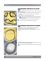
Abutment - Biogeneric individual - MultiLayer ............................................... 109
8.1.1 Create a new restoration.................................................................... 109
8.1.2 Acquiring a preparation ...................................................................... 109
8.1.3 Editing the model ............................................................................... 110
8.1.4 Bite registration .................................................................................. 110
8.1.5 Set model axis.................................................................................... 110
8.1.6 Mask areas......................................................................................... 110
8.1.7 Select Scanbody ................................................................................ 110
8.1.8 Editing gingiva lines ........................................................................... 110
8.1.9 Define restoration axis ....................................................................... 111
8.1.10 Adjusting parameters ......................................................................... 111
8.1.11 Editing the restoration ........................................................................ 112
8.1.12 Grinding of restoration layers ............................................................. 112
8.2
Abutment - Biogeneric individual................................................................... 112
8.2.1 Create a new restoration.................................................................... 113
8.2.2 Acquiring a preparation ...................................................................... 113
8.2.3 Editing the model ............................................................................... 113
8.2.4 Bite registration .................................................................................. 114
8.2.5 Set model axis.................................................................................... 114
6
63 75 914 D3534
D3534.208.03.03.02 03.2013
Sirona Dental Systems GmbH
8.3
8.4
8.5
63 75 914 D3534
D3534.208.03.03.02
8.2.6 Mask areas........................................................................................
114
8.2.7 Select Scanbody ...............................................................................
114
8.2.8 Editing gingiva lines ..........................................................................
114
8.2.9 Define restoration axis ......................................................................
115
8.2.10 Adjusting parameters ........................................................................
115
8.2.11 Editing the restoration .......................................................................
116
8.2.12 Grinding the restoration.....................................................................
116
Abutment - FrameWork ................................................................................
116
8.3.1 Create a new restoration...................................................................
116
8.3.2 Acquiring a preparation .....................................................................
117
8.3.3 Editing the model ..............................................................................
117
8.3.4 Bite registration .................................................................................
117
8.3.5 Set model axis...................................................................................
117
8.3.6 Mask areas........................................................................................
117
8.3.7 Select Scanbody ...............................................................................
118
8.3.8 Editing gingiva lines ..........................................................................
118
8.3.9 Define restoration axis ......................................................................
119
8.3.10 Adjusting parameters ........................................................................
119
8.3.11 Editing the restoration .......................................................................
119
8.3.12 Grinding the restoration.....................................................................
119
Bars ..............................................................................................................
119
8.4.1 Create a new restoration...................................................................
120
8.4.2 Acquiring a preparation .....................................................................
121
8.4.3 Editing the model ..............................................................................
121
8.4.4 Bite registration .................................................................................
121
8.4.5 Set model axis...................................................................................
121
8.4.6 Mask areas........................................................................................
122
8.4.7 Drawing the preparation margin........................................................
122
8.4.8 Defining axes ....................................................................................
122
8.4.9 Adjusting parameters ........................................................................
123
8.4.10 Editing the restoration .......................................................................
124
8.4.11 Grinding the restoration.....................................................................
124
Attachments .................................................................................................
124
8.5.1 Create a new restoration...................................................................
124
8.5.2 Acquiring a preparation .....................................................................
125
8.5.3 Editing the model ..............................................................................
125
8.5.4 Bite registration .................................................................................
126
8.5.5 Set model axis...................................................................................
126
03.2013
7
båÖäáëÜ
Operator's Manual
Sirona Dental Systems GmbH
Operator's Manual
8.5.6 Mask areas......................................................................................... 126
8.5.7 Drawing the preparation margin......................................................... 126
8.5.8 Defining axes ..................................................................................... 126
8.5.9 Adjusting parameters ......................................................................... 127
8.5.10 Editing restorations ............................................................................ 127
8.5.11 Grinding the restoration...................................................................... 128
8.6
Model ............................................................................................................ 128
8.6.1 Create a new restoration.................................................................... 129
8.6.2 Acquiring a preparation ...................................................................... 129
8.6.3 Editing the model ............................................................................... 129
8.6.4 Bite registration .................................................................................. 130
8.6.5 Set model axis.................................................................................... 130
8.6.6 Editing restorations ............................................................................ 130
8.6.7 Aligning the model.............................................................................. 130
8.6.8 Adjusting parameters ......................................................................... 131
8.6.9 Segmentation ..................................................................................... 131
8.6.10 Undercutting segments ...................................................................... 132
8.6.11 Placing pins........................................................................................ 132
8.6.12 Closing the model .............................................................................. 133
9
10
Tips and Tricks ......................................................................................................... 134
9.1
Service program ............................................................................................ 134
9.2
Shortcut keys ................................................................................................ 134
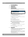
inLab Stack SW 4.2.................................................................................................. 138
10.1
Getting started............................................................................................... 138
10.1.1 Installing the software ........................................................................ 138
10.1.2 Copy protection .................................................................................. 138
10.1.3 Starting the software .......................................................................... 139
10.2
User interface ................................................................................................ 139
10.2.1 System menu ..................................................................................... 139
10.2.1.1Saving a stack.................................................................................. 140
10.2.1.2Importing a stack.............................................................................. 140
10.2.1.3Exporting a stack.............................................................................. 141
10.2.1.4Importing an element ....................................................................... 141
10.2.1.5Exporting an element ....................................................................... 141
10.2.1.6License manager.............................................................................. 141
10.2.1.7Configuration.................................................................................... 142
8
63 75 914 D3534
D3534.208.03.03.02 03.2013
Sirona Dental Systems GmbH
10.2.1.8Window mode..................................................................................
142
10.2.1.9Current program version .................................................................
142
10.2.1.10Closing the software......................................................................
142
10.2.2 Phase bar..........................................................................................
143
10.2.3 Start window......................................................................................
143
10.2.3.1Creating a new stack.......................................................................
143
10.2.3.2Opening a stack ..............................................................................
143
10.2.3.3Removing a stack............................................................................
144
10.2.4 Step menu.........................................................................................
144
Configuration ................................................................................................
144
10.3.1 Parameters........................................................................................
144
10.3.2 Model parameters .............................................................................
145
10.3.3 Devices .............................................................................................
145
10.3.4 Options ..............................................................................................
146
10.3.4.1Odontogram ....................................................................................
146
10.3.4.2Reset notes .....................................................................................
146
10.3.4.3Legend proof ...................................................................................
146
10.3.4.4Display legend.................................................................................
147
10.3.4.5Generate name automatically .........................................................
147
10.3.4.6Calculate stacks automatically ........................................................
147
Edit orders ....................................................................................................
147
10.4.1 COLLECT phase...............................................................................
147
10.4.2 STACK phase ...................................................................................
148
10.4.3 MILL phase .......................................................................................
148
Sirona Connect portal..............................................................................................
149
11.1
Starting the Sirona Connect portal ...............................................................
149
11.2
Log in to the portal........................................................................................
149
11.3
Order list.......................................................................................................
149
11.4
Restoration data ...........................................................................................
149
11.5
Order information .........................................................................................
149
11.6
Additional information...................................................................................
150
11.7
Displaying the order sheet............................................................................
150
11.8
Checking the model......................................................................................
150
10.3
10.4
11
63 75 914 D3534
D3534.208.03.03.02
03.2013
9
båÖäáëÜ
Operator's Manual
Sirona Dental Systems GmbH
Operator's Manual
11.9
Accepting/rejecting an order ......................................................................... 150
11.10 Order list appears automatically.................................................................... 151
Index......................................................................................................................... 152
10
63 75 914 D3534
D3534.208.03.03.02 03.2013
Sirona Dental Systems GmbH
1 Introduction
Operator's Manual
1
Introduction
Introduction
1.1 Dear Customer,
General
description
Dear Customer,
Thank you for purchasing your inLab SW 4 software from Sirona.
In connection with inEos Blue / inLab MC XL, this software enables you
to produce dental restorations, for example from ceramic material with a
natural appearance.
Improper use and handling can create hazards and cause damage.
Therefore, please read and carefully follow this manual and the relevant
operating instructions. always keep them within easy reach.
To prevent personal injury or material damage, it is important to observe
all safety information.
To safeguard your warranty claims, please complete the attached
Installation Report / Warranty Passport when the system is handed over
and send it to the indicated fax number.
Your Team
Your
inLab SW 4 Team
1.2 Copyright and trademark
Copyright and trademark
Copyright
© Sirona Dental Systems GmbH. Alle Rechte vorbehalten.
The information contained in this manual may be changed without notice.
The software, including the associated documentation,is protected by
copyright. You must therefore handle it in the same way as any other
protected material.
Anyone who copies this software to any medium for any purpose other
than his own personal use without the written permission of Sirona Dental
Systems will be liable to prosecution.
Trademarks
Trademarks
Microsoft® and Windows 7® are registered trademarks.
WindowsTM is a trademark of Microsoft Corporation.
All other trademarks are the property of their respective holders.
3rd party code libraries
Notes on 3rd party code libraries must be stored in license.pdf in the
installation directory.
63 75 914 D3534
D3534.208.03.03.02
03.2013
11
båÖäáëÜ
In order to master the system safely, you should train on the exercise
model using the described examples.
2 General information
Sirona Dental Systems GmbH
2.1 General safety information
Operator's Manual
2
General information
General information
Please read this document completely and follow the instructions exactly.
You should always keep it within reach.
Original language of the present document: German
2.1 General safety information
General safety information
Only use original software
Only use original software or software which has been released by
Sirona. To produce restorations, manipulated or non-released software
components must not be used.
Software and software components must not be installed using incorrect
data.
Please check that each installed component has been granted approval
in its country. Contact your dealer for more information.
For the USA only
For the USA only
CAUTION: According to US Federal Law, this product may be sold only
to or by instruction of physicians, dentists, or licensed professionals.
2.2 Accessories
Product safety
Accessories
In order to ensure product safety, this device may be operated only with
original Sirona accessories or third-party accessories expressly approved
by Sirona. The user assumes the risk of using non-approved accessories.
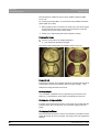
Available accessories
Available accessories
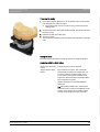
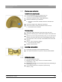
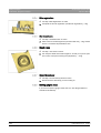
● Scanbodies for Bluecam S, REF 62 34 681
● Scanbodies for Bluecam L, REF 62 34 699
● Scanbodies for Omnicam S, REF 64 31 386
● Scanbodies for Omnicam L, REF 64 31 394
● ScanPost (Also observe the ScanPost Operating Instructions)
2.3 Structure of the manual
Structure of the manual
2.3.1
Identification of the danger levels
Identification of the danger levels
To prevent personal injury and material damage, please observe the
warning and safety instructions provided in this document, which are
highlighted as follows:
DANGER
Imminent danger that could result in serious bodily injury or death.
12
63 75 914 D3534
D3534.208.03.03.02 03.2013
Sirona Dental Systems GmbH
2 General information
Operator's Manual
WARNING
Potentially dangerous situation that could result in serious bodily injury
or death.
CAUTION
Potentially dangerous situation that could result in slight bodily injury.
NOTICE
Potentially harmful situation which could lead to damage of the product
or an object in its environment.
IMPORTANT
Instructions for use and other important information.
2.3.2
båÖäáëÜ
Tip: Information for simplifying work.
Formats and symbols used
Formats and symbols used
The formats and symbols used in this document have the following
meaning:
✔ Prerequisite
Requests you to do something.
1. First action step
2. Second action step
or
➢ Alternative action
Result
2.3.3
See “Formats and symbols
used [ → 13]”
Identifies a reference to another
text passage and indicates the
relevant page number.
● List
Identifies a list item.
"Command / menu item"
Identifies commands / menu items
or a quote.
Conventions
Conventions
Example
Meaning
Clicking
Single pressing and subsequent release of the left
mouse button or the left trackball button on the
acquisition unit
Double-clicking
Double pressing and release in quick succession of
the left mouse button or left trackball button on the
acquisition unit
Moving the mouse On the acquisition unit: Moving the trackball in the
in one direction
corresponding direction.
Seizing a point
63 75 914 D3534
D3534.208.03.03.02
03.2013
Pressing the left mouse button (left trackball button
on the acquisition unit) and keeping it pressed.
13
2 General information
Sirona Dental Systems GmbH
2.3 Structure of the manual
Operator's Manual
Example
Meaning
For acquisitions
with the CEREC
Bluecam: Actuate
foot switch
The same function as: Pressing the left trackball
button on the acquisition unit or the left mouse
button.
"Ctrl+N"
On the keyboard: Press the Ctrl and N keys
simultaneously.
Drag & drop
(Drag & drop)
Press and hold an element (e.g. pictograph), and
drop onto new potential destination.
2.3.4
Formats of the manual
You can access the manual via the Help button or by pressing "F1".
Formats of the manual
PDF
The pdf-format user manual can be found on the supplied software DVD
or on the Internet (http://www.sirona.com/manuals).
This format is page-oriented and is well suited for printing out the desired
pages.
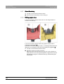
2.3.5
Odontogram used
Odontogram used
The software can be adjusted to the international odontogram (FDI) or the
USA odontogram (ADA) (Odontogram [ → 41]).
In this documentation teeth are named as follows:
2.3.6
Principle:
FDI
(#ADA)
Example:
13
(#6)
File format
File format
You can assign one or more orders to any dentist in the software.
Depending on the processing status, an order comprises multiple optical
impressions, the virtual models reconstructed from them and one or more
virtual restorations.
The software uses its own file format (*.lab) to export an order. This
format contains all of the order data. LAB files can be opened with other
inLab software installations. Under certain circumstances, older software
versions cannot open data exports from a more recent version.
14
63 75 914 D3534
D3534.208.03.03.02 03.2013
Sirona Dental Systems GmbH
3 Getting started
Operator's Manual
3
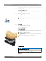
Getting started
Getting started
3.1 Installing the software
Firmware
V2.00
Installing the
software
The software requires the 2.00 firmware version of the license stick.
Update the firmware version if necessary. For more information, refer to
the section on License manager [ → 22].
Administrator rights
NOTICE
Installation only with administrator rights
✔ Version 2.00 of the firmware is available.
✔ The PC is powered up and all programs are terminated.
1. Insert the DVD in the DVD drive.
The setup program starts automatically.
2. If this is not the case, run the "Setup.exe" file in the root directory of
the DVD.
The installation wizard opens.
3. Click the "OK" button.
4. In the next dialog, click the "Next" button.
The license agreement is shown.
5. Read through the license agreement carefully.
6. If you accept the license agreement, then activate the "I accept the
terms in the license agreement" option button and confirm your
acceptance by clicking the "Next" button.
7. In the next dialog, click the "Next" button.
8. In the next dialog, click the "Install" button.
The program continues the installation routine. This may take
several minutes.
9. Click the "Finish" button once installation is complete.
The software is installed.
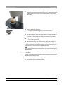
3.2 Uninstalling the software
Uninstalling the software
✔ The program is closed.
1. Click on "Start / All Programs / Sirona Dental Systems / inLab / Tools
/ Deinstallation" to uninstall the software.
During the uninstall procedure, you will be asked whether you
want to delete the patient data or the entries in the registration
database (e.g. the calibration data).
2. Depending on your decision, click either the "Yes" or "No" button.
The software is uninstalled.
63 75 914 D3534
D3534.208.03.03.02
03.2013
15
båÖäáëÜ
You must have administrator rights on the PC on which you want to
install the software!
3 Getting started
Sirona Dental Systems GmbH
3.3 Copy protection
Operator's Manual
3.3 Copy protection
USB
stick inLab
Copylicense
protection
The software can be started only when the USB license stick is plugged
in. The USB license stick is included in the scope of supply of the units. If
you require additional licenses, please contact your dealer.
Always keep the USB license stick near the unit.
All authorizations (milling, interface, software licenses) can be installed as
electronic licenses on the USB license stick. You must enter a 25-digit
license key for this purpose.
You will receive the license key along with the unit. Alternatively, you can
order it separately from your dealer.
Following an update, you may require a new license that is not available
on your USB license stick. For more information, refer to the section on
License manager [ → 22].
3.4 Downloading the software
Downloading the software
ServicePacks
To keep your software updated, regularly check whether new
ServicePacks are available.
inLab SW
Visit the Sirona website at www.sirona.com. In the product area for digital
dental care, you will find the download area with the products for inLab
laboratory solutions.
You will also find a description of the improvements and enhancements
made in the ServicePack.
Update
Update
You have to pay for major software changes (upgrades), and these also
require a license. If you do not have a new license, you can only work in
the demo version.
Contact your dealer for information on how to obtain new licenses for an
upgrade.
3.5 Starting the software
Starting the software
✔ The inLab SW software is installed. You will find the start icon on the
desktop.
✔ The USB license stick is connected with a valid, current license.
➢ Double-click the inLab SW start icon.
or
➢ Click on "Start / All Programs / Sirona Dental Systems/ inLab /
inLab SW 4".
The software is started.
16
63 75 914 D3534
D3534.208.03.03.02 03.2013
Sirona Dental Systems GmbH
4 User interface
Operator's Manual
User interface
User interface
båÖäáëÜ
4
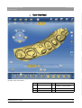
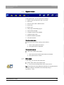
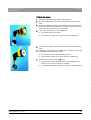
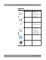
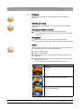
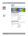
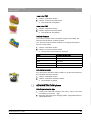
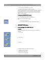
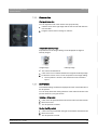
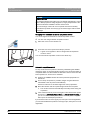
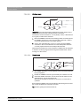
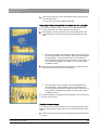
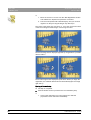
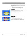
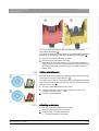
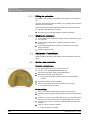
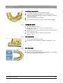
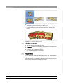
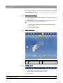
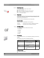
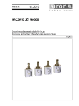
Overview of the user interface
Legend inLab SW
63 75 914 D3534
D3534.208.03.03.02
03.2013
A
Phase bar
E
Object bar
B
System menu
F
Image catalog (can only be
activated in "SCAN" phase)
C
Page palette
G
Main window
D
Step menu
H
Tool wheel
17
4 User interface
Sirona Dental Systems GmbH
4.1 Phase bar
Operator's Manual
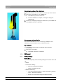
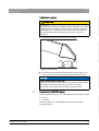
Bridge
I
Detailed representation of bridge / bar
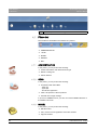
4.1 Phase bar
Phase bar
The workflow is illustrated in the software in 5 phases.
Phase bar
● ADMINISTRATION
●
SCAN
● MODEL
● DESIGN
● MILL
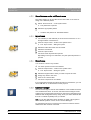
4.1.1
ADMINISTRATION
In this phase, you can perform the following:
ADMINISTRATION
● Create restorations and determine their type
● Define a milling unit
● Select material
4.1.2
SCAN
In this phase, you can perform the following:
SCAN
inLab SW
● Acquisitions with inEos Blue
- lower jaw,
- upper jaw,
- buccal bite registration
● View a 3D preview of the acquisitions
● Activate other image catalogs
If you have a CEREC license, you also can use the CEREC Bluecam or
the CEREC Omnicam.
4.1.3
MODEL
In this phase, you can perform the following:
MODEL
● Edit the model
● Carry out the buccal registration of the bite situation
● Align the models
18
63 75 914 D3534
D3534.208.03.03.02 03.2013
Sirona Dental Systems GmbH
4 User interface
Operator's Manual
● Trim models
● Draw in prep lines
● Define insertion axes
● Define restoration axes if necessary (abutments and telescopes only)
● Select the patient photo for Smile Design
4.1.4
DESIGN
DESIGN
In this phase, you can perform the following:
● Individually change restoration parameters
● Have initial restoration suggestions generated
● Rotate and position the restoration
4.1.5
båÖäáëÜ
● Form and process restorations
MILL
In this phase, you can perform the following for each restoration:
MILL
● Define a milling machine
● Define milling options (not possible for all materials)
● Determine the block size
● Check and adapt the positioning of the restoration in the block
● Define the sprue location of the restoration
● Start the milling process
● Export the restoration/model for the inLab Stack SW or as *.stl
(additional license required)
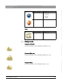
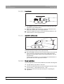
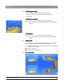
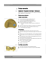
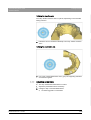
4.2 Object bar
Object bar
The buttons for restoration selection are located in the object bar.
Each restoration is represented by a tooth with the corresponding tooth
number. You can switch back and forth between the teeth by clicking on
the corresponding tooth symbol.
inLab bridges
Active elements are highlighted in orange.
If restorations span multiple tooth positions or two objects per tooth
position are selectable for multilayer, the object bar is extended
downwards. You can change between different active elements in the
extended area.
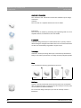
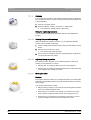
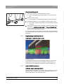
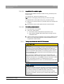
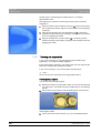
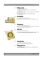
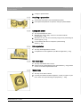
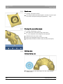
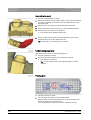
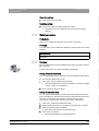
4.3 Tool wheel
Description
Tool wheel of CEREC SW 4
The tool wheel makes the standard tools available in the MODEL and
DESIGN phases in order to simplify access. The tools currently available
vary depending on the current step.
1. Right-click in the workspace.
The tool wheel opens.
63 75 914 D3534
D3534.208.03.03.02
03.2013
19
4 User interface
Sirona Dental Systems GmbH
4.4 Step menu
Operator's Manual
2. Click with the right mouse button anywhere in the workspace.
The tool wheel moves to the position of the mouse pointer.
3. Select a tool.
The selected tool is available. The tool wheel closes
automatically.
You also can close the tool by clicking in the workspace with the left
mouse button.
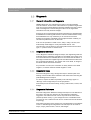
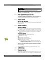
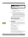
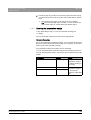
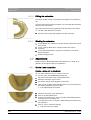
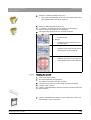
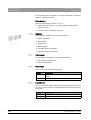
4.4 Step menu
General
description
Step menu
Each phase is divided into steps. They are shown in the step menu at the
bottom edge of the screen. The step menu changes depending on which
phase the current restoration is in.
This menu guides you through the process step-by-step.
The double arrow keys can be used to switch between steps and phases.
Double arrow keys
Mandatory steps
Mandatory steps
Mandatory steps are marked with a red or green bar.
20
Red bar:
The step has not yet been completed successfully.
Green bar:
The step has been completed successfully.
63 75 914 D3534
D3534.208.03.03.02 03.2013
Sirona Dental Systems GmbH
4 User interface
Operator's Manual
4.5 System menu
System menu
In the system menu, you can perform the following:
● Switch to the start window to start a new case
● Save case
● Save the case under a different name
● Import case
● Export case
● Call up App Center/start plug-ins
båÖäáëÜ
● Open license manager
● Configure hardware and software
● Change window mode
● Retrieve software information
● Close the software
Opening the system menu
Opening system menu
➢ Move the mouse cursor to the top of the window.
or
➢ Click on the system menu button.
The system menu is displayed.
Closing the system menu
Closing system menu
➢ Click on the system menu button.
or
➢ Click into the main window with the left mouse button.
The system menu is closed.
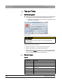
4.5.1
Save case
Save case
In this dialog, you can save the actual case.
➢ Select "Save Case" in the system menu.
The current processing status of the case is saved.
Save restorations or export them for the stack software
Tip: The procedure for saving individual restorations or exporting them for
the stack software is described in the section Exporting a
restoration [ → 105] .
63 75 914 D3534
D3534.208.03.03.02
03.2013
21
4 User interface
Sirona Dental Systems GmbH
4.5 System menu
Operator's Manual
4.5.2
Save the case under a different name
Save the case under a different name
This dialog allows you to save the current case under a new name or
assign it to a different patient.
1. Select "Save Case As..." in the system menu.
The patient list is opened.
2. Select the appropriate patient.
or
➢ Create a new patient via "Add New Patient".
4.5.3
Import case
Import case
✔ The LAB file (or older CDT file) is stored on the inLab 4 PC or on a
storage medium connected to it.
1. Click the "Import Case..." button in the system menu.
The "Import Case..." dialog box opens.
2. Select the folder where the case is located.
3. Select the relevant file.
4. Click the "Open" button
The case is then imported and opened.
Depending on the type of restoration, only the optical impression is
opened.
4.5.4
Export case
Exporting
Export case
You can store a case in any location.
✔ You have opened a case in the software.
1. Click the "Export Case..." button in the system menu.
The "Export Case..." dialog box opens.
2. Select the target folder to which you want to export the case.
3. Assign any name to the case.
4. Click on the "Save" button.
The case is exported as an LAB file.
Transfer
If you would like to transfer the optical impression to another PC, you can
use a USB stick or a network drive for this purpose.
4.5.5
License manager
The license manager is used for the installation of new software licenses
on the USB license stick. To do this, start the license manager via the
system menu and follow the instructions on the screen. Keep the license
certificate with 25-digit license key ready, which you either obtained with
the unit or ordered separately from your dealer.
License manager
Tip: You can also start the license manager via "Start / All Programs /
Sirona Dental Systems / inLab / Tools / License Manager".
To activate the license you must have an Internet connection and the
USB license stick must be connected.
22
63 75 914 D3534
D3534.208.03.03.02 03.2013
Sirona Dental Systems GmbH
4 User interface
Operator's Manual
License texts and third-party libraries
Licenses and code libraries
For information on licenses and code libraries from third parties, see
licenses.pdf. The file is in the installation directory under "C:/Programs/
Sirona Dental Systems/CADCAM".
4.5.6
Configuration
The configuration is described in the chapter "Configuration [ → 26]".
Configuration
4.5.7
Window mode
Window mode
4.5.8
båÖäáëÜ
The "Window Mode" function can be used to exit full-screen mode or
enter it again.
Current program version
Current program version
CEREC SW 4
The "About" function contains information about the current program
version.
4.5.9
Closing the software
Closing the software
Closing CEREC SW 4
The "Exit" function can be used to close the software.
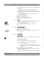
4.6 Start window
inLab
SW 4 start window options
Start window
In the start window, you can perform the following:
● Create or select an order
● Edit order data
● Search for an order
● Open cases
● Delete cases
● Add cases
63 75 914 D3534
D3534.208.03.03.02
03.2013
23
4 User interface
Sirona Dental Systems GmbH
4.6 Start window
Operator's Manual
Switching to the start window
Switching to the start view
You can switch to the start view at any time.
1. Open the system menu.
2. Click on the "Start Screen" button.
4.6.1
Creating a new order
Creating a new order
In the data structure, orders are uniquely identified by one of the following
two entries:
● Name of the dentist and name of the patient
or
● Name of the dentist and order number
Add order
1. If the dentist concerned has already been created, click on the
dentist.
2. Click on the"Add New Order"button.
A job order card opens. The name of the dentist that you
preselected is then suggested.
3. Enter the name of the dentist and the name of the patient.
or
➢ Enter the name of the dentist and the order number.
Once you have entered enough information, the bar in the"Edit
Order"step turns from red to green.
4. Click on the"Add New Case"button.
The program switches over to the"ADMINISTRATION"phase.
4.6.2
Edit order data
Edit order data
4.6.2.1
Edit job order card
✔ You have found the order in the overview.
Edit job order card
1. Click the job order card.
2. Click on the "Edit Order" step in the step menu.
The job order card is opened for editing.
3. Carry out the changes.
4. Confirm your changes by clicking the "Ok" button.
The changes are saved in the memory.
5. Click the double arrow on the left side of the step menu.
The overview is displayed.
24
63 75 914 D3534
D3534.208.03.03.02 03.2013
Sirona Dental Systems GmbH
4 User interface
Operator's Manual
4.6.2.2
Remove order
✔ You have found the order in the overview.
Remove order
1. Click on the case you would like to remove.
2. Click on the "Delete Order" step in the step menu.
3. Confirm the deletion by clicking the "Ok" button.
The order is deleted.
4.6.2.3
Deleting a case
✔ You have found the associated order in the overview.
Deleting a case
1. Click on the order.
2. Select the case.
3. Click on the "Delete Case" step in the step menu.
4. Confirm the deletion by clicking the "Ok" button.
4.6.2.4
båÖäáëÜ
The case is deleted.
Opening a case
✔ You have found the associated order in the overview.
Opening a case
1. Click on the order.
2. Select the case.
3. Click on the "Open Case" step in the step menu.
The restoration is opened.
4.6.2.5
Adding a new case
✔ You have found the associated order in the overview.
Adding a new case
1. Click on the order.
2. Click on the "Add New Case" step in the step menu.
The program switches over to the "ADMINISTRATION" phase.
63 75 914 D3534
D3534.208.03.03.02
03.2013
25
5 Configuration
Sirona Dental Systems GmbH
5.1 Parameters
Operator's Manual
5
Configuration
The "Configuration" menu contains five sub-menus:
Configuration
● Parameters
● Devices
● Options
● Settings
● Apps
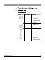
5.1 Parameters
The "Parameters" menu is structured by restoration type. You can make
the settings for each of the following restoration types.
Parameters
The changes in the values are displayed graphically.
Changed parameter settings are accepted for all initial suggestions here.
Tip
Tip: If you want to change the parameter values only for one restoration,
do this in the DESIGN phase in the step "Restoration Parameters".
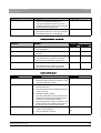
Crown, inlay, veneer parameters
Crown, inlay, onlay and veneer
Parameters
Description
Default value
Crown
Inlay/
Onlay
Veneer
Spacer
80µm
● Possibility for setting the space for the
fastening material below the restoration. Acts
up to the preparation margin.
80µm
80µm
Marginal Adhesive Gap
● Adjust width of space on preparation margin.
-
60µm
-
-
-
500µm
0µm
0µm
0µm
2µm
-
● The value of the adhesive gap cannot exceed
the spacer value.
Veneer Thickness
● Set to minimum thickness.
● The software tries not to fall below this
thickness when calculating the restoration
suggestions.
● DESIGN and MILLphases:
The value is displayed as a semitransparent
geometry on the preparation. Areas where the
thickness falls short of the minimum level in
the design phase are thus made visible.
Occlusal Milling Offset
● Apply or remove material in the occlusal
direction over the entire occlusal surface.
● This value concerns only the milling result.
● DESIGN and MILL phases:
The effects are not visible.
Proximal Contacts Strength
● Set the thickness of the approximal contacts. 25µm
● The software tries to achieve this stored
thickness in the restoration suggestions.
26
63 75 914 D3534
D3534.208.03.03.02 03.2013
Sirona Dental Systems GmbH
5 Configuration
Operator's Manual
Parameters
Description
Occlusal Contacts Strength
● Set the thickness of the occlusal contacts.
Default value
Crown
Inlay/
Onlay
Veneer
25µm
2µm
-
500µm
500µm
-
ON
ON
● The software tries to achieve this stored
thickness in the restoration suggestions.
Minimal Thickness (Radial)
● Set the minimum wall thickness in the
horizontal direction.
● The software tries not to fall below this
thickness when calculating the restoration
suggestions.
båÖäáëÜ
● DESIGN and MILL phases:
The value is displayed on the preparation as a
semitransparent geometry together with the
minimum occlusal thickness and the
instrument geometry setting. Areas where the
thickness falls short of the minimum level in
the design phase are thus made visible.
● Observe the material manufacturer's
recommendations when setting the minimum
thickness.
● Can be switched on and off
Minimal Thickness (Occlusal)
● Set the minimum wall thickness in the occlusal 700µm
direction.
ON
● The software tries not to fall below this
thickness when calculating the restoration
suggestions.
700µm
-
ON
● DESIGN and MILL phases:
The value is displayed on the preparation as a
semitransparent geometry together with the
minimum radial thickness and the instrument
geometry setting. Areas where the thickness
falls short of the minimum level in the design
phase are thus made visible.
● Observe the material manufacturer's
recommendations when setting the minimum
thickness.
● Can be switched on and off
Margin Thickness
● Reinforce restoration margins with additional
material.
–
Simplifies handling of the restoration
–
Prevents splitting of the material
50µm
50µm
50µm
ON
ON
ON
● The additional material can be milled off
manually before inserting the restoration.
● Can be switched on and off
63 75 914 D3534
D3534.208.03.03.02
03.2013
27
5 Configuration
Sirona Dental Systems GmbH
5.1 Parameters
Operator's Manual
Parameters
Description
Default value
Crown
Regard Instrument Geometry
Considers the instrument geometry in the bottom YES
of the restoration.
Inlay/
Onlay
Veneer
YES
YES
YES
YES
Areas of the preparation that are smaller than the
diameter of the instrument geometry are
calculated in the bottom of the restoration so that
they increase with the instrument geometry.
Remove Undercuts
Undercuts within the preparation margin are
blocked out in the restoration bottom.
YES
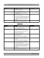
Abutment parameters (anatomic, framework, bottom layer)
Abutment (anatomical, framework, lower layer)
Parameters
Description
Default value
Anatomi Framew Lower
cal
ork
layer
Proximal Contacts Strength
● Determines the thickness of a contact in the
mesial or distal direction.
25µm
-
-
Occlusal Contacts Strength
● Determines the thickness of a contact in the
occlusal direction (to the antagonist).
25µm
-
-
Minimal Thickness (Radial)
● Determines the minimum radial wall thickness 500µm
of the abutment.
ON
Minimum amount of material required around
the adhesive base to produce a stable
abutment.
500µm
500µm
ON
ON
700µm
700µm
ON
ON
● Can be switched on and off
Minimal Thickness (Occlusal)
700µm
● Determines the minimum occlusal wall
thickness of the abutment.
ON
Minimum amount of material required around
the adhesive base to produce a stable
abutment.
● Can be switched on and off
Gingival Placement Pressure
● Determines how strongly the initial suggestion 0µm
for the abutment penetrates the gingiva in
order to build up pressure on the gingiva.
0µm
-
Gingival Depth
● Determines how far below or above the
preparation margin the gingiva lies in
reference to the gingival line.
0µm
0µm
-
Shoulder Width
● Width of the shoulder of an abutment or
telescope.
-
1000µm 1000µm
Telescope Angle
● Telescope angle of an abutment or telescope. -
28
4°
4°
63 75 914 D3534
D3534.208.03.03.02 03.2013
Sirona Dental Systems GmbH
5 Configuration
Operator's Manual
Crown parameters (framework, telescope)
Crown (framework, telescope)
Parameters
Description
Default value
Framework
Spacer
80µm
● Possibility for setting the space for the
fastening material below the restoration. Acts
up to the preparation margin.
Minimal Thickness (Radial)
● Set the minimum wall thickness in the
horizontal direction.
● The value determines the radial wall thickness
of the crown cap.
Telescope
80µm
500µm
500µm
ON
ON
båÖäáëÜ
● DESIGN and MILL phases:
The value is displayed on the preparation as a
semitransparent geometry together with the
minimum occlusal thickness and the
instrument geometry setting. Areas where the
thickness falls short of the minimum level in
the design phase are thus made visible.
● Can be switched on and off
Minimal Thickness (Occlusal)
● Set the minimum wall thickness in the occlusal 700µm
direction.
ON
● The value determines the occlusal wall
thickness of the crown cap.
700µm
ON
● DESIGN and MILL phases:
The value is displayed on the preparation as a
semitransparent geometry together with the
minimum radial thickness and the instrument
geometry setting. Areas where the thickness
falls short of the minimum level in the design
phase are thus made visible.
● Can be switched on and off
Margin Thickness
● Reinforce restoration margins with additional
material.
–
Simplifies handling of the restoration
–
Prevents splitting of the material
50µm
50µm
ON
ON
● The additional material can be milled off
manually before inserting the restoration.
● Can be switched on and off
Telescope Angle
● Angle by which the outer wall of the telescope cone is inclined inward in relation to the
restoration axis.
4°
Telescope Height
● Initial height of the outer wall of the telescope cone from the cervical shoulder to the junction
to the occlusal surface.
3000µm
● It influences the size of the friction surface.
63 75 914 D3534
D3534.208.03.03.02
03.2013
29
5 Configuration
Sirona Dental Systems GmbH
5.1 Parameters
Operator's Manual
Parameters
Occlusal Shoulder Width
Description
● Width of the occlusal shoulder at the junction
between the outer wall of the telescope cone
and the occlusal surface.
●
Regard Instrument Geometry
Default value
Framework
Telescope
-
300µm
YES
YES
YES
YES
The occlusal shoulder is inclined inward 45° in
relation to the telescope axis.
● Considers the instrument geometry in the
bottom of the restoration.
● Areas of the preparation that are smaller than
the diameter of the instrument geometry are
calculated in the bottom of the restoration so
that they increase with the instrument
geometry.
Remove Undercuts
● Undercuts within the preparation margin are
blocked out in the restoration bottom.
Attachment parameters
Attachment
Parameters
Description
Default value
Attachment Diameter
● Diameter of the cylindrical anchor of the
positive part.
1500
Attachment Height
● Height of the entire positive part.
2000
Attachment Bridge Length
● Length of male bridge.
The male bridge is the connecting element
between the anchor and the base.
1000
Attachment Bridge Width
● Width of bridge.
1000
Attachment Gingiva Distance
● Distance from male bottom to gingival
adaptation.
0
● Negative values result in a penetration of the
gingiva.
Attachment Gingiva Adaption
● Gingival adaptation: yes / no
YES
Attachment Spacer Value
● Divided attachment:
Space between positive part and cut-out
negative part in neighboring positive part.
80µm
Attachment Shoulder Width
● Size of plate located on the gingiva.
500µm
Bar parameters
Bar
Parameters
Description
Bar Height
● Describes the height of the bar segment in µm. 3000
Bar Width
● Describes the width of the bar segment in µm. 3000
Bar Cone Angle
● Describes the angle of incidence of lateral and 4°
friction surfaces in degrees.
●
30
Default value
Applies only to primary bars (design mode
squared).
63 75 914 D3534
D3534.208.03.03.02 03.2013
Sirona Dental Systems GmbH
5 Configuration
Operator's Manual
Parameters
Description
Default value
Bar Smoothing Radius
● Describes the radius of the junction between
the anchor element and the bar in µ.
This should guarantee a smooth junction
between the anchor and the bar and prevent
predetermined breaking points.
2500 µm
Bar Interdental Space
● Space in µm required to ensure easy cleaning. 1000 µm
This space is left in the anchor-bar transition
zone between the bar and the gingiva.
Pontic parameters (anatomic)
Pontic (anatomical, framework)
Description
Default value
Anatomical
Framework
Gingival Spacing
● Space between pontic and preparation
geometry/gingiva.
0
0
Lingual Opening Angle
● Increase of pontic for the basal area in the oral 0
direction.
0
Proximal Contacts Strength
● Set the thickness of the approximal contacts. 25µm
-
båÖäáëÜ
Parameters
● The software tries to achieve this stored
thickness in the restoration suggestions.
Occlusal Contacts Strength
● Set the thickness of the occlusal contacts.
25µm
-
● The software tries to achieve this stored
thickness in the restoration suggestions.
Multilayer crown parameters (bottom layer)
Crown (bottom layer)
Parameters
Description
Default value
Spacer
80µm
● Possibility for setting the space for the
fastening material below the restoration. Acts
up to the preparation margin.
Occlusal Milling Offset
● Set the minimum wall thickness in the
horizontal direction.
0µm
● The value determines the radial wall thickness
of the crown cap.
● DESIGN and MILL phases:
The value is displayed on the preparation as a
semitransparent geometry together with the
minimum occlusal thickness and the
instrument geometry setting. Areas where the
thickness falls short of the minimum level in
the design phase are thus made visible.
Minimal Thickness (Radial)
63 75 914 D3534
D3534.208.03.03.02
03.2013
● Determines the minimum radial wall thickness 500µm
in the horizontal direction.
ON
● Can be switched on and off
31
5 Configuration
Sirona Dental Systems GmbH
5.1 Parameters
Operator's Manual
Parameters
Description
Default value
Minimal Thickness (Occlusal)
● Determines the minimum radial wall thickness 700µm
in the occlusal direction.
ON
● Can be switched on and off
Telescope Angle
● Angle by which the outer wall of the telescope 4°
cone is inclined inward in relation to the
restoration axis.
Regard Instrument Geometry
● Considers the instrument geometry in the
bottom of the restoration.
YES
● Areas of the preparation that are smaller than
the diameter of the instrument geometry are
calculated in the bottom of the restoration so
that they increase with the instrument
geometry.
Remove Undercuts
● Undercuts within the preparation margin are
blocked out in the restoration bottom.
YES
Multilayer crown parameters (top layer)
Crown (top layer)
Parameters
Description
Spacer
● Possibility for setting the space for the
80µm
fastening material below the restoration. Acts
up to the preparation margin.
Default value
Occlusal Milling Offset
● Apply or remove material in the occlusal
direction over the entire occlusal surface.
0µm
● This value concerns only the milling result.
● DESIGN and MILL phases:
The effects are not visible.
Minimal Thickness (Radial)
● Set the minimum wall thickness in the
horizontal direction.
● The software tries to achieve this stored
thickness in the restoration suggestions.
500µm
ON
Minimal Thickness (Occlusal)
● Set the minimum wall thickness in the occlusal 700µm
direction.
ON
● The software tries to achieve this stored
thickness in the restoration suggestions.
Regard Instrument Geometry
● Considers the instrument geometry in the
bottom of the restoration.
YES
● Areas of the preparation that are smaller than
the diameter of the instrument geometry are
calculated in the bottom of the restoration so
that they increase with the instrument
geometry.
Remove Undercuts
32
● Undercuts within the preparation margin are
blocked out in the restoration bottom.
YES
63 75 914 D3534
D3534.208.03.03.02 03.2013
Sirona Dental Systems GmbH
5 Configuration
Operator's Manual
Model
Model
Observe the information supplied concerning the pins, model holders and
base plates.
Parameters
Description
Segmentation Cut Width
● Set the width of the saw-cut.
Baseplate Distance
● Adjust the distance of the base plates from each other.
Pin Diameter
● Set the diameter of the pins.
Pin Spacing
● Set the distance of the pins from each other.
Virtual articulator
Parameters
Description
Default values
Arms
● Set the side length for the Bonwill triangle
105µm
Base
● Set the intercondylar distance
100µm
Balkwill Angle
● Set the Balkwill angle
23°
båÖäáëÜ
The preset parameters are mean values which can be used without
alteration for an average articulation.
● Affects the height of the incisal point
Sagital
● Set the condylar path inclination
35°
Bennett
● Create Bennett angle
15°
Accepting settings
➢ Click on the "Ok" button.
Discarding settings
➢ Click on the "Cancel" button.
Resetting settings
Resetting settings
➢ Click on the "Reset All Group Parameter" button.
The settings for this restoration type are reset to the factory
settings.
5.2 Devices
All connected devices can be displayed and configured under the menu
item "Devices".
Devices
A green check mark on a device indicates its availability.
Adding devices (automatically)
Adding devices automatically
You can add additional devices with the "Scan for New Devices" function.
✔ The device is attached to the PC.
1. Click on the "Scan for New Devices" button.
All devices attached to the PC are detected. You will be prompted
to enter a name for new devices.
2. Enter a name for the new device.
63 75 914 D3534
D3534.208.03.03.02
03.2013
33
5 Configuration
Sirona Dental Systems GmbH
5.2 Devices
Operator's Manual
Adding devices (manually)
Adding devices (manually)
You can manually add devices with the "Add Device (Manual)" function.
This is mandatory for devices which cannot be operated at the maximum
speed of 115,200 baud. This applies to devices with long cable
connections or certain radio modules (e.g. Futaba, 19200 baud).
1. Click on the "Add Device (Manual)" button.
2. Select whether the device is connected to the network or in series.
3. Network: Enter the network address.
In series: Enter the COM port and the baud rate.
4. Click on the "Ok" button.
The software attempts to contact the device.
If the connection fails, check that it is correctly established. If necessary,
contact a qualified technician.
Refreshing CEREC SW 4
Refresh status
With the "Refresh Devices" button, you can
● refresh the status display, e.g. check whether a milling unit has
finished milling or
● check the current availability of a device.
5.2.1
inEos Blue
inEos Blue
Under the menu item "inEos Blue", inEos Blue can be set.
Setting
Description
Shake tolerance
● Set motion sensitivity for automatic
activation.
● The more exact the setting, the longer
you have to hold the model still before
taking the next scan.
Applying/discarding settings
Accepting settings
➢ Click on the "Ok" button.
Discarding settings
➢ Click on the "Cancel" button.
5.2.1.1
Resetting settings
Resetting settings
➢ Click on the "Reset inEos Blue Settings" button.
The settings are reset to factory settings.
5.2.1.2
Calibration
Calibration
1. Click on the "Calibrate" button.
2. Then simply proceed as prompted by the software.
Also observe the operating instructions of the inEos Blue.
34
63 75 914 D3534
D3534.208.03.03.02 03.2013
Sirona Dental Systems GmbH
5 Configuration
Operator's Manual
5.2.1.3
XYZ calibration
XYZ calibration
1. Click on the "Calibrate XYZ" button.
2. Then simply proceed as prompted by the software.
Also observe the operating instructions of the inEos Blue.
5.2.2
CEREC Bluecam
inLab;
on CEREC license
CERECnote
Bluecam
A CEREC SW 4.0 license and a CEREC SW 4.2 license must be present
in order to use the CEREC Bluecam.
Settings
Setting
Description
Shake tolerance
● Set motion sensitivity for automatic
activation.
● The more stringent the setting, the
longer you have to hold the camera still
before the next acquisition will be taken.
Auto-delete rejected
images
● Images that could not be reconstructed/
overlaid with the current acquisitions are
automatically moved to the Recycle Bin.
Applying/discarding settings
Accepting settings
➢ Click on the "Ok" button.
Discarding settings
➢ Click on the "Cancel" button.
5.2.2.1
Resetting settings
Resetting settings
➢ Click on the "Reset Camera Settings" button.
The settings are reset to factory settings.
5.2.2.2
Calibration
Calibration
1. Click on the "Calibrate" button.
2. Then simply proceed as prompted by the software.
5.2.3
CEREC Omnicam
inLab;
on CEREC license
CERECnote
Omnicam
A CEREC SW 4.0 license and a CEREC SW 4.2 license must be present
in order to use the CEREC Bluecam.
Camera mode
Using the "Camera Mode:" function, you can choose between intraoral or
extraoral measurements.
Audio feedback
Audio feedback
Using the "Sound:" selection box, you can switch the audio feedback for
acquisitions on or off. You can control the volume using the slide bar.
63 75 914 D3534
D3534.208.03.03.02
03.2013
35
båÖäáëÜ
Under the menu item "Camera", CEREC Bluecam can be set up.
5 Configuration
Sirona Dental Systems GmbH
5.2 Devices
Operator's Manual
Accepting settings
➢ Click on the "Ok" button.
Discarding settings
➢ Click on the "Cancel" button.
5.2.3.1
Resetting settings
➢ Click on the "Reset Camera Settings" button.
The settings are reset to factory settings.
5.2.3.2
Calibrating CEREC Omnicam
The measurement procedure used by the system requires the use of a
calibrated CEREC Omnicam. The CEREC Omnicam is factory calibrated.
If calibration is required, you can use the supplied CEREC Omnicam
calibration set for this purpose. The supplied calibration set and a USB
stick form a single unit.
Recalibrate the CEREC Omnicam in the following cases:
● following transport (shaking stress) or during first commissioning
● after storage in unheated or un-air-conditioned rooms (temperature
differences exceeding 30°C)
● with temperature differences of over 15°C between the last
calibration and operation
Prior to the first calibration
The serial number of the calibration set to be used has been set on the
CEREC AC with Omnicam at the factory. Prior to the first calibration after
changing the PC and when switching the calibration set, you must enter
the serial number of the calibration set to be used in the software. If you
do not wish to do this, you can continue with "Start calibration [ → 36]".
When entering the serial number, the following steps should be followed:
1. Start the CalibRegistry.exe application on the USB stick included with
delivery of the calibration set.
2. Enter the 8-digit Sirona ID. You can find the ID on the sticker on the
calibration set.
With all future calibration work involving the "2011" software, you
will be prompted to use this calibration set.
Start calibration
1. In the software, navigate to the system menu, and click on the
"Configuration" button.
2. Click the "Devices" button.
3. Click the "Omnicam" button.
4. Click the "Calibrate" button.
The camera view is displayed in one window.
5. Follow the prompt to set up the calibration set with the corresponding
ID number. At this point, check that this ID matches the ID on your
calibration set. If this is not the case, go back to "Prior to the first
calibration [ → 36]".
36
63 75 914 D3534
D3534.208.03.03.02 03.2013
Sirona Dental Systems GmbH
5 Configuration
Operator's Manual
Calibration
Calibrate the camera
1. Remove the protective cap from the calibration set.
2. Mount the calibration set on the tip of the camera until it locks into
place.
3. Secure the CEREC Omnicam in the calibration set using one hand.
Ensure that the external calibration set screw is fully screwed in in a
clockwise motion until it gently locks into place.
4. Click on the "OK" button on your CEREC AC.
The measuring process starts.
5. Turn the screw counter-clockwise until you reach the next latching
point.
6. Click on the "OK" button on your CEREC AC. In doing so, ensure that
the CEREC Omnicam does not move.
The software confirms the calibration process.
The software prompts you to proceed to the next latching.
7. Execute steps 5 and 6 a total of 11 times.
The software provides status updates on the calibration and
informs you once the procedure is complete.
You will be prompted to measure the position of the exit window.
63 75 914 D3534
D3534.208.03.03.02
03.2013
37
båÖäáëÜ
The software prompts you to proceed to the next latching.
5 Configuration
Sirona Dental Systems GmbH
5.2 Devices
Operator's Manual
Measuring the position of the exit window
1. Mount the bottom side of the calibration set to the tip of the camera.
2. Click on the "OK" button on your CEREC AC.
The calibration process is continued.
Once the calibration is complete, a message is displayed
indicating this.
3. Confirm the message by clicking the "OK" button on your CEREC AC.
The CEREC Omnicam is calibrated.
Error message during calibration
Error message during calibration
The software indicates if an error occurs during calibration. If the
calibration process resulted in errors, restart the process.
End calibration
✔ The software indicates that the calibration was completed
successfully.
➢ Click on the "OK" button.
The CEREC Omnicam is calibrated.
5.2.4
5.2.4.1
Milling unit
Editing settings
inLab MC XL
You can subsequently edit the following settings via the menu item "MC
XL":
● Name
● Connection settings
–
Retrieve IP settings automatically
–
Specify IP settings manually
● Manual block fixing
38
–
If you use manual block fixing, a check mark must be placed in
front of "Manual block fixation".
–
Models can only be milled using manual block fixation.
63 75 914 D3534
D3534.208.03.03.02 03.2013
Sirona Dental Systems GmbH
5 Configuration
Operator's Manual
● Second motor set
–
The check mark must be placed in front of "Two Bur Sets".
–
You can deactivate bur sets individually. A deactivated bur set
will simply be ignored during milling, calibration etc.
NOTICE! The restoration may be damaged if longer milling
instruments are present in the deactivated bur set than in the
active set. Ensure that the milling instruments installed in the
deactivated bur set are not longer than those in the active set.
● Scanner
–
If the milling unit has an integrated scanner, a check mark must
be placed in front of "Scanner".
–
Use the scanner to read bar codes.
–
If a bar code reader is used, this option must be activated.
● External tank
–
If the external water tank is connected and the check mark has
been placed, you will not be reminded to change the water until
a later point in time.
inLab
inLab
You can subsequently edit the following settings via the menu item
"CEREC 3/inLab":
● Name
● Connection settings
● Large water tank
- If the 25-liter canister (option, Order No. 60 56 217) is connected
and the check mark has been placed, you will not be reminded to
change the water until a later point in time.
- If the 25-liter canister is retrofitted, your service engineer must place
a check mark in the box in front of "Large water tank".
● Scanner
- If the "CEREC 3/inLab" milling unit has an integrated scanner
(option, Order No. 58 33 707) a check mark must be placed in front
of "Scanner".
- If a scanner is retrofitted, your service engineer must place a check
mark in front of "Scanner".
5.2.4.2
Calibration
Calibration
1. Click on the "Calibrate" button.
2. Then simply proceed as prompted by the software.
5.2.4.3
Changing instruments
Changing instruments
1. Click on the "Change Instruments" button.
2. Then simply proceed as prompted by the software.
63 75 914 D3534
D3534.208.03.03.02
03.2013
39
båÖäáëÜ
● Bar code reader
5 Configuration
Sirona Dental Systems GmbH
5.3 Options
Operator's Manual
5.2.4.4
Removing the milling unit
Removing the milling unit
1. Click on the "Delete Device" button.
2. Then simply proceed as prompted by the software.
5.3 Options
Options
5.3.1
Bite registration
Bite registration
Here you can set whether the image catalog is offered for bite
registration.
Setting
Description
Activate
The image catalog is offered for bite registration.
Deactivate
The image catalog is not offered for bite registration.
You can carry out bite registration in the MODEL phase.
The buccal bite registration must be used.
5.3.2
Virtual articulator
Virtual articulator
Use Articulation:
Setting
Description
Activate
The articulator is displayed to the right-hand side of the
page palette during the construction. It can be activated
at any time for constructing the restorations.
Deactivate
The articulator is not displayed to the right-hand side of
the page palette during the construction.
Use Articulation for initial proposal:
Setting
Description
YES
The dynamic contact points are taken into consideration
in the initial suggestion.
NO
Only the static contact points are taken into
consideration in the initial suggestion.
The dynamic contacts are identified by color (occlusal
compass acc. to Schulz).
5.3.3
Smile Design
Smile Design
40
Setting
Description
Activate
The Smile Design function is available and can be
activated for the respective case under "Options" in the
phase ADMINISTRATION .
Deactivate
The Smile Design function is not offered in the
ADMINISTRATION phase.
63 75 914 D3534
D3534.208.03.03.02 03.2013
Sirona Dental Systems GmbH
5 Configuration
Operator's Manual
5.4 Settings
The menu item "Settings" has the following subitems:
Settings
5.4.1
Odontogram
Odontogram
You can set the odontogram using "ADA/FDI Notation":
● International ("FDI Notation")
● USA ("ADA Notation")
Reset notes
båÖäáëÜ
5.4.2
Reset notes
Here, all warnings can be displayed again.
5.4.3
Setting
Description
YES
Displays all the deactivated warnings in the workflow
again.
NO
Warnings which were previously hidden, remain hidden.
Checking restoration parameters
Checking restoration parameters
Here, you can select whether the restoration parameters will be displayed
during the construction.
Setting
Description
YES
The restoration parameters are displayed before the
restoration is calculated.
You can change the values.
NO
5.4.4
The parameters are not displayed. The values set under
"Configuration" / "Parameters" are used.
Database
Database
In the "Patient Database" menu item, you can select where patient data
and cases are saved.
You can specify a folder for this data. This allows you, for example, to
save all data on a secure server on the practice network.
Alternatively, you can manage patient data with SIRONA SIDEXIS
software and save cases in a database created in SIDEXIS.
63 75 914 D3534
D3534.208.03.03.02
03.2013
41
5 Configuration
Sirona Dental Systems GmbH
5.5 App Center (applications)
Operator's Manual
5.4.5
Calculating restorations
inLab
Calculating restorations
Using "Restoration Calculation" you can define the behavior on entering
the "DESIGN" phase.
Setting
Description
YES
On entering the "DESIGN" phase, suggestions for all
restorations are automatically calculated, for which the
preparation margin and the insertion axis/restoration
axis have been defined.
If this option is activated, it may result in lengthy
computing times when editing numerous restorations.
NO
5.4.6
Upon entering the "DESIGN" phase, only the
restoration proposal for the currently active tooth
number is calculated.
Auto-hide the page palette
Auto-hide the page palette
The page palette will automatically be minimized if you use a tool.
CEREC SW 4 settings
This setting affects the phases MODEL and DESIGN.
Setting
Description
YES
After selecting a tool, the palette will be minimized and
only the symbol of the active tool will be displayed.
The entire palette opens again when the mouse is
positioned over it.
Tip: Use this setting if you frequently work with the tool
wheel.
NO
5.4.7
Provided a tool is selected, the tool palette will always
be displayed in its entirety and with all options.
Selecting a language
Selecting a language
Here, you can set the language of the software. Once the software is
rebooted, the language is set to your choice.
5.5 App Center (applications)
App Center (applications)
Via the Sirona App (Application) Center, you have access to various apps
(applications) for our CAD CAM products. Furthermore, you have access
to a website that shows you the apps available. The website also contains
additional information on where you can download the apps.
42
63 75 914 D3534
D3534.208.03.03.02 03.2013
Sirona Dental Systems GmbH
6 Restoration types and design mode
Operator's Manual
6
Restoration types and design mode
Restoration types and design mode
6.1 Restoration types
Restoration types
Single tooth restoration
Symbol
Restoration type
Design mode
Crown
● Biogeneric Individual
(Split: MultiLayer)
● FrameWork
● Biogeneric Copy
(Split: MultiLayer)
båÖäáëÜ
● Biogeneric Reference
(Split: MultiLayer)
● Telescope
Inlay/Onlay
● Biogeneric Individual
● Biogeneric Copy
Veneer
● Biogeneric Individual
● Biogeneric Copy
● Biogeneric Reference
Abutment
● Biogeneric Individual
(Split: MultiLayer)
● FrameWork
● Biogeneric Copy
(Split: MultiLayer)
● Biogeneric Reference
(Split: MultiLayer)
63 75 914 D3534
D3534.208.03.03.02
03.2013
43
6 Restoration types and design mode
Sirona Dental Systems GmbH
6.1 Restoration types
Operator's Manual
Bridge restoration
Bridge restoration
Symbol
Restoration type
Design mode
Crown
● Biogeneric Individual
● FrameWork
● Biogeneric Copy
● Biogeneric Reference
● Telescope
Inlay/Onlay
● Biogeneric Individual
● Biogeneric Copy
Veneer
● Biogeneric Individual
● Biogeneric Copy
● Biogeneric Reference
Pontic
● Biogeneric Individual
(Split: MultiLayer)
● FrameWork
● Biogeneric Copy
(Split: MultiLayer)
● Biogeneric Reference
(Split: MultiLayer)
Missing
Connector
● Intersection
● Anatomic
44
63 75 914 D3534
D3534.208.03.03.02 03.2013
Sirona Dental Systems GmbH
6 Restoration types and design mode
Operator's Manual
Symbol
Restoration type
Design mode
Bar
● Cylindric
● Squared
● Dolder
● Hader
Attachment
● Cylindric
Restoration type
Design mode
Model
Symbol
båÖäáëÜ
Model
Model
6.2 Design mode
Design mode
Biogeneric Individual
For more information, refer to "Biogeneric Individual [ → 47]“.
Biogeneric Reference design mode
Biogeneric Reference
For more information, refer to "Biogeneric Reference [ → 47]“.
Biogeneric Copy design mode
Biogeneric Copy
For more information, refer to "Biogeneric Copy [ → 47]“.
63 75 914 D3534
D3534.208.03.03.02
03.2013
45
6 Restoration types and design mode
Sirona Dental Systems GmbH
6.2 Design mode
Operator's Manual
Anatomic / Intersection design mode
Anatomic / Intersection
The "Anatomic" and "Intersection" modes are available only for bridge
connectors.
Anatomic
The connector is a separate element and can be edited.
Intersection
The connector is created by penetrating the neighboring teeth. It is not a
separate element, and therefore cannot be edited.
Framework design mode
Framework
Select this design technique to create frameworks or primary sections
without taking the antagonist information into account. These frameworks
are then not automatically suggested to support cusps.
Telescope design mode
Telescope
Select the "Telescope" design technique to set telescope elements for
bridges. The telescope elements of a bridge are always aligned parallel.
Bars design mode
Bars
You can select the following geometries for the bars:
Cylindric
Squared
Dolder
Hader
Multilayer design mode
Multilayer
However, the fully anatomical shape is broken down into a framework
with no undercut and the covering layer by this technique. The two parts
can be milled from different materials.
Do not use this design technique if you want to manually veneer a
framework.
46
63 75 914 D3534
D3534.208.03.03.02 03.2013
Sirona Dental Systems GmbH
6 Restoration types and design mode
Operator's Manual
6.3 Biogeneric
Biogeneric
6.3.1
General information on Biogeneric
General information on Biogeneric
CEREC Biogeneric is a software that is able to reconstruct lifelike
occlusal surfaces. On the basis of the features of a patient's single intact
tooth, the program extrapolates the naturally created morphology of other
teeth. The biogeneric occlusal design functions for all single tooth
restorations and fully anatomic bridges.
Previously, all occlusal design approaches were based on dental libraries
and databases containing data records of various standard teeth. Today,
these databases are only enlisted if you do not want to have the
biogeneric suggestion calculated from the adjacent teeth. Instead, you
can select a preference form for the tooth.
It will now be possible to create crowns, inlays, onlays, veneers, and
anatomically sized bridges in a fully automated manner. The
reconstruction can be based on any intact patient tooth from the same
type, i.e. posterior tooth or anterior tooth.
6.3.2
Biogeneric Individual
Biogeneric Individual
In the "Biogeneric Individual" design technique, the neighboring teeth are
analyzed and the restoration suggestion is calculated on this basis. The
more information that is available, the more successful the calculation. A
full image of at least one neighboring tooth should therefore be taken from
the occlusal/incisal direction. For anterior and corner teeth, an image of
the labial surface should also be taken.
For premolars or molars, the calculation is mainly based on the distal
neighbor, for anterior teeth the mesial neighbor is used.
6.3.3
Biogeneric Copy
Biogeneric Copy
Select the "Biogeneric Copy" design technique to transfer parts of an
existing occlusal surface to the restoration and enhance the rest using the
patented Biogeneric technique.
To do this, acquire the status separately in the "BioCopy Upper" or
"BioCopy Lower" image field prior to the preparation.
This technique can be used for inlays, onlays, partial crowns, crowns, and
bridges.
6.3.4
Biogeneric Reference
Biogeneric Reference
Select the "Biogeneric Reference" design technique for user definition of
the tooth to be used as a reference for calculating the restoration
suggestion. The reference tooth can be any tooth of the same class
(anterior/posterior tooth), e.g. the antagonist or the contralateral tooth.
You also can use a reference tooth from a model to achieve the desired
morphology.
This reference tooth must be acquired on a separate basis in the "BioRef
Lower" or "BioRef Upper" image field. This technique can be used for
inlays, onlays, partial crowns, crowns, and bridges.
63 75 914 D3534
D3534.208.03.03.02
03.2013
47
båÖäáëÜ
Crowns, inlays, onlays, veneers, and fully anatomical bridges - inLab
7 Edit orders
Sirona Dental Systems GmbH
7.1 Tools and functions of the page palette
Operator's Manual
7
Edit orders
Edit orders
The Shortcut keys [ → 134] chapter describes how the following tools and
options can be called using shortcut keys.
7.1 Tools and functions of the page palette
Tools and functions of the page palette
The page palette offers you various different functions, depending on the
current step.
7.1.1
Views
Local/Global
Views
In the view options, you can select whether the selection is to be applied
to the restoration (Local) or the 3D patient photo.
Local
Local
You can use the "View Options" button to display six predefined views in
the Local area.
● "Mesial"
● "Distal"
● "Buccal" / "Labial"
● "Lingual"
● "Cervical"
● "Occlusal" / "Incisal"
Global
Global
You can use the "View Options" button to display six predefined views in
the Global area.
● "Top"
● "Bottom"
● "Right"
● "Left"
● "Front"
● "Back"
Changing the view
Changing the view
1. Click on the "View Options" button.
2. Click on one of the proposed views.
The virtual model rotates to the corresponding view.
Enlarging or reducing the view
Enlarging or reducing the view
1. Click on the "View Options" button.
2. Position the mouse pointer over the center tooth icon and press and
hold the left mouse button.
The icon then changes to a magnifying glass.
48
63 75 914 D3534
D3534.208.03.03.02 03.2013
Sirona Dental Systems GmbH
7 Edit orders
Operator's Manual
3. Pull the mouse button up or down.
The virtual model is then enlarged or reduced.
Tip: You also can use the mouse scrollwheel to enlarge or reduce the
view.
7.1.2
Tools
Tools
The most important tools are also offered to you in the tool wheel. For
more information on the tool wheel, refer to the section Tool wheel [ → 59].
You will find all tools as a submenu under "Tools".
Tip: To prevent automatic minimization of the tool window, go to the
configuration under "Options" and select the option 'No' in the "ToolMenu".
Tip: You can cancel the current tool with the stop icon (top right).
Undo and reset
With the "Undo" button in the tools you can undo the last change made.
With the "Reset" button you can reset changes that were made with the
tool.
7.1.2.1
Buccal registration
Buccal registration
Displacing a buccal image
With the "Drag Buccal" function, you can displace the buccal image.
1. Click on the "Buccal" button.
2. Click on the "Drag Buccal" button.
3. Click on the buccal image and displace it to the same region on the
upper and the lower jaw.
The image is accepted.
Tip: If an image is not accepted, align the jaw buccally. This
enables better overlapping.
If registration is still not possible, check whether the buccal
sections in the jaws and in the buccal image are sufficient.
4.
If the image was accepted, move the image to the corresponding
region of the opposite jaw.
Flipping the buccal acquisition
Rotating a buccal image
With the "Flip Buccal Impression" function, you can rotate the buccal
image.
1. Click on the "Buccal" button.
2. Click on the "Flip Buccal Impression" button.
The buccal image is then rotated.
63 75 914 D3534
D3534.208.03.03.02
03.2013
49
båÖäáëÜ
Undo and reset
7 Edit orders
Sirona Dental Systems GmbH
7.1 Tools and functions of the page palette
7.1.2.2
Operator's Manual
Buccal bite tools
Buccal bite tools
You can adjust the occlusion using the following tools.
Move jaw
Using the "Align Jaw" function, you can correct the buccal bite by
positioning and rotating the upper jaw.
➢ Click on the "Align Jaw" button.
The rotating/positioning tool will be shown.
Settling
Using the "Settling" function, you can state areas that are not to be taken
into account in bite determination.
1. Click the "Settling" button.
2. Using the left mouse button, select the area on a jaw half that is not
to be taken into account in bite determination.
3. Click on "Apply".
The software will restart the buccal registration.
7.1.2.3
Shaping
With the "Form" function, you can
Shaping
● apply
● remove
● or smooth material.
Space bar tip
Tip: When one of the shape tools is activated, you can also switch to the
following order using the space bar on the keyboard:
Apply > Remove > Smooth > Apply > ...
Applying material
Apply material
1. Click on the "Form" button.
2. Click on the "Add" button.
3. Click with the mouse cursor on the area you wish to shape.
4. Press and hold the left mouse button and apply the material to the
surface location by moving the mouse.
Removing material
Removing material
1. Click on the "Form" button.
2. Click on the "Remove" button.
3. Press and hold the left mouse button and remove the material from
the surface location by moving the mouse.
50
63 75 914 D3534
D3534.208.03.03.02 03.2013
Sirona Dental Systems GmbH
7 Edit orders
Operator's Manual
Smoothing
Smoothing
When smoothing, you can smooth the surface locally.
1. Click on the "Form" button.
2. Click on the "Smooth" button.
3. Click with the mouse cursor on the location you wish to smoothen.
4. Press and hold the left mouse button and smoothen the surface
location by moving the mouse.
Properties
Modifying the size
You can use the "Size" button to modify the size of the area affected. The
area affected is shown as an orange colored area. The size of the area
affected can be modified for each forming tool.
Resizing
2. Click the "Size" button and press and hold the mouse button.
3. Pull the mouse cursor up or down.
The size of the orange area is enlarged or reduced. The size is
shown on the restoration.
Tip: You can also change the size by clicking on the restoration with the
right mouse button and, while holding the right mouse button down,
dragging the mouse up or down.
Hiding the neighboring restoration
Hiding the neighboring restoration
You can hide the neighboring restoration with the "Hide Neighbors"
function.
7.1.2.4
Cutting off model regions
Cutting off model regions
Cutting with CEREC SW 4
With the "Cut" function, you can cut out model areas The cut out model
areas are then discarded. You cannot display cut out areas later on.
Remove model area
Activity
With the "Discard Part" function, model areas can be removed.
When performing this activity, be careful not to accidentally cut out any
areas that e.g. are located behind the model or are otherwise cut away
from the line.
1. Click on the "Cut" button.
2. Begin the cut line with a double-click.
3. Click to set additional points.
4. Finish the cut by double clicking.
The model area is cut off.
Invert model area
With the "Invert Selected" function, the model area that is cut out can be
inverted.
63 75 914 D3534
D3534.208.03.03.02
03.2013
51
båÖäáëÜ
1. Click on the "Form" button.
7 Edit orders
Sirona Dental Systems GmbH
7.1 Tools and functions of the page palette
Operator's Manual
✔ The "Cut" tool is selected.
✔ You have created a cut.
➢ Click on the "Invert Selected" button.
The model area which was cut out is displayed.
The rest of the model area is hidden.
Tip: You can invert the model area that is cut out by double-clicking on
the semitransparent cut-out area.
7.1.2.5
Correcting defects
With the "Replace" function, you can correct defects and artifacts on the
model (e.g. holes or elevations).
Correcting defects
To do so, drag a line around the defect in your model and select the
appropriate function.
1. Click on the "Replace" button.
2. Set the starting point with a double-click.
3. Click to set further points in order to enclose the defect tightly. The
line must be located completely on the model.
4. Set the line end by double-clicking.
The line is finalized.
Tip: You can use delete to remove the line.
5. Click on the "Apply" button.
Tip: The tool can also be triggered by pressing the Enter key.
The software smoothens everything within the line by
interpolation.
7.1.2.6
Resetting changes
Resetting changes
The "Reset Model" function is used to reset all changes.
1. Click on the "Tools" button.
2. Click on the "Reset Model" button.
The program will ask whether you really want to reset all
changes.
3. Confirm with "Ok".
7.1.2.7
Trimming
With the "Trim" function, you can isolate the preparation. You can thus
Trimming
e.g. draw in the preparation margin more easily. Trimmed image regions
can be optionally displayed and hidden later on.
Remove part
Hiding image regions
The "Discard Part" function enables you to hide image regions.
The trim line also can be placed over the preparation line. Only the region
underneath the preparation will then be hidden automatically. The
prepared region remains fully intact.
1. Click on the "Trim" button.
2. Click on the "Discard Part" button.
3. Start by double-clicking in the vicinity of the model or on the model.
52
63 75 914 D3534
D3534.208.03.03.02 03.2013
Sirona Dental Systems GmbH
7 Edit orders
Operator's Manual
4. Click to set additional points. Draw the line close to the preparation
around which you want to trim.
5. Finish the line by double clicking.
The smaller region of the model is hidden.
Invert selected
Inverting an image region
With the "Invert Selected" function, the hidden image region can be
inverted.
✔ An image region has been hidden using the "Trim" tool.
➢ Click on the "Invert Selected" button.
The hidden image region will be shown.
The image region shown will be hidden.
7.1.2.8
Entering the preparation margin
General
Entering the preparation margin
For further information on using this tool, see the section Entering the
preparation margin [ → 101].
Automatic edge detection
Automatic edge detection
With "Margin" / "Auto", you can work with automatic edge detection.
1. Click on the "Margin" button.
2. Click on the "Auto" button.
Automatic edge detection is switched on.
Interpolating technique
Manual drawing
With "Manual" you can draw in the preparation margin manually. With this
technique, you must place the individual points close together in order to
clearly define the contour of the preparation margin even in difficult
situations.
✔ The "Margin" tool is open.
➢ Click on the "Manual" button.
The manual technique is switched on.
Interpolating technique with intensity image
Manual drawing with intensity image
With "Manual with intensity image" you can manually draw in the
preparation margin on the intensity image.
✔ The "Margin" tool is open.
➢ Click on the "Manual with intensity image" button.
The manual technique with intensity image is switched on.
Tip: As long as the "Margin" tool is activated, you can switch back and
forth between the drawing options by pressing the space bar.
63 75 914 D3534
D3534.208.03.03.02
03.2013
53
båÖäáëÜ
Tip: You can invert the hidden image region by double-clicking on the
semitransparent hidden region.
7 Edit orders
Sirona Dental Systems GmbH
7.1 Tools and functions of the page palette
7.1.2.9
Operator's Manual
Positioning
With the "Move" function, you can displace, rotate, and scale the
restoration.
Positioning
Displacing and rotating
Displacing and rotating
With the "Position and Rotate" tool, you can displace and rotate the
restoration.
Displacing and rotating the restoration
➢ Left-click on an arrow symbol and hold the button down.
You can displace or rotate the restoration in the corresponding
direction.
Changing axes
➢ Right-click on an arrow symbol and hold the button down.
You can change the axis on which the object is rotated or moved.
Scaling
Scaling
With the "Scale" function, you can change the size of the restoration. The
area affected is shown as an orange-colored area.
1. Click the "Move" button.
2. Click the "Scale" button.
3. Drag the mouse cursor to the restoration until the desired area is
highlighted.
4. Hold the left mouse button down and drag the mouse to enlarge or
reduce the restoration.
The orange-colored area will be expanded or reduced.
Layout
Effect
Drag the mouse to enlarge or reduce the entire
restoration.
Drag the mouse to enlarge or reduce the
restoration in the bucco-lingual direction.
Drag the mouse to enlarge or reduce restoration in
the mesio-distal direction.
54
63 75 914 D3534
D3534.208.03.03.02 03.2013
Sirona Dental Systems GmbH
7 Edit orders
Operator's Manual
7.1.2.10
Shaping
The "Shape" function enables you to shape a selected region.
Shaping
You can shape the restoration in 3 ways:
Function
Description
Auto
The software preselects the movement axis based on
the screen perspective.
2-Direction
The movement is possible along one axis orthogonal
to the restoration surface.
4-Direction
The movement is possible along two axes parallel to
the restoration surface.
Automatic
Anatomic
båÖäáëÜ
The "Auto" function is used to preselect regions of morphology, e.g.
cusps or fissure lines, for designing.
Manual
Circular
The "Manual" is used to preselect a circular region for designing.
Properties:
Modifying the size
Modifying the size
This option is available only for the circular variant.
You can use the "Size" button to modify the size of the area affected. The
area affected is shown as an orange colored area.
1. Click on the "Shape" button.
2. Click the "Size" button and press and hold the mouse button.
3. Pull the mouse cursor up or down.
The size of the orange area is enlarged or reduced. The size is
shown on the restoration.
Tip: You can also change the size by clicking on the restoration with the
right mouse button and, while holding the right mouse button down,
dragging the mouse up or down.
Scale whole
Overall scaling
The option is only available for the automatic tool.
You can use the "Scale Whole" button to change the overall size of the
restoration.
Hiding the neighboring restoration
Hiding the neighboring restoration
You can hide the neighboring restoration with the "Hide Neighbors"
function.
63 75 914 D3534
D3534.208.03.03.02
03.2013
55
7 Edit orders
Sirona Dental Systems GmbH
7.1 Tools and functions of the page palette
7.1.2.11
Operator's Manual
Contacts
If you modify the restoration, the contact surfaces also will be displaced.
The "Contacts" function is used to reset the contacts to the thickness set
in the parameters.
Contacts
1. Click the "Contacts" button.
2. Click the "Mesial", "Distal", "Occlusal", or "FGP" button.
The respective contact surface is then reset.
Hiding the neighboring restoration
Hiding the neighboring restoration
You can hide the neighboring restoration with the "Hide Neighbors"
function.
7.1.2.12
Varying Biogeneric Morphology
With the "Biogeneric Variation" function, you can generate different
variants of the possible morphology.
Varying Biogeneric Morphology
1. Click the "Biogeneric Variation" button and press and hold the mouse
button.
2. Pull the mouse cursor up or down.
The morphology is then changed.
3. Let go of the mouse button when the morphology that is optimal for
your purposes becomes visible.
7.1.2.13
Adjusting the sprue position
The "Sprue" function enables you to rotate the position of the sprue
location on the restoration in 2 ways:
Adjusting the sprue position
● Step-by-step, by clicking on the arrow in the circle segment.
● Continuously, by clicking and holding the left mouse button inside the
circle segment and moving the mouse.
7.1.2.14
Moving the block
Moving the block
Displace
The"Position"function enables you to displace the block surrounding the
restoration in all spatial directions until the restoration strikes one of the
block margins.
You can move the block in 3 ways:
● Step-by-step, by clicking on one of the arrows showing the movement
axes on the semitransparent cube.
● Continuously in 2 directions, by clicking on one side of one of the
cube surfaces, holding the button down and moving the mouse.
● Continuously in all 4 directions, by clicking in the center of a cube
surface, holding the button down and moving the mouse.
56
63 75 914 D3534
D3534.208.03.03.02 03.2013
Sirona Dental Systems GmbH
7 Edit orders
Operator's Manual
Rotate
With the "Rotate"function, you can rotate the restoration about the axis of
the block.
You can rotate the restoration in the block in 2 ways:
● Step-by-step, by clicking on the arrow in the circle segment.
● Continuously, by left-clicking on or inside of the circle segment and
moving the mouse.
7.1.2.15
Reduce
With the "Reduce" function, you can anatomically reduce the restoration:
You also can perform partial reductions.
Reduce
2. Double-click on the restoration and draw a closed line.
Tip: You can use the space bar or "Toggle area" to switch the area to be
reduced. It is displayed as an orange colored area.
Properties
Reduction strength
Use "Reduction Strength" to set the reduction strength.
1. Click the "Reduce" button.
2. Click the "Reduction Strength" button and press and hold the mouse
button.
3. Change the reduction strength by moving the mouse up or down.
Attaching the pontic to the gingiva
Attaching the pontic to the gingiva
If the "Stick Pontic Base to Gingiva" function is active, the base of the
pontic is not reduced for a full reduction.
Hiding the neighboring restoration
Hiding the neighboring restoration
You can hide the neighboring restoration with the "Hide Neighbors"
function.
7.1.2.16
Incisal variation
Using the "Incisal Variation" function, you can generate textures
(mamelons) for front teeth.
Incisal variation
1. Click the "Incisal Variation" button.
2. Using the left mouse button, click on the controller and draw the
mouse downwards to set the thickness of the textures on the teeth.
3. Click with the left mouse button on the tooth to move the texture on
the tooth.
63 75 914 D3534
D3534.208.03.03.02
03.2013
57
båÖäáëÜ
1. Click the 'Reduce' button.
7 Edit orders
Sirona Dental Systems GmbH
7.1 Tools and functions of the page palette
7.1.2.17
Operator's Manual
Using a gingival mask
In the step "Click Scanbody", you can select whether or not the gingival
mask is to be used for calculating the emergence profile. This option is
available only if a gingival mask was acquired in the "SCAN" phase.
Using a gingival mask
7.1.2.18
Scale
You can use this tool for frameworks, telescopes, multilayer frameworks
and bars.
Scale
In the tool menu, you can select whether the tool is to be effective in the
radial or the occlusal direction. You can toggle between these directions
with the space bar or with the mouse.
1. Place the mouse pointer on an active restoration.
Various design elements are then offered, depending on the
restoration type.
An arrow shows the direction in which the scaling will occur. The
area affected is shown highlighted in orange.
2. Press and hold down the left mouse button.
3. Move the mouse to change the object.
Radial/occlusal
Radial/occlusal
You can edit the edge of the crown caps and bridge frameworks for the
restoration type FrameWork in radial or occlusal direction.
1. Click on the "Scale" button.
2. Click on either "Radial" or "Occlusal" as applicable.
3. Place the mouse pointer on an active restoration.
The area affected is shown highlighted in orange.
4. Press and hold down the left mouse button.
5. Move the mouse to change the object.
Properties
Modifying the size
If a check mark is placed in front of "Complete" the area affected is
maximized and applies to the entire design element. If no check mark is
placed, you can determine the area affected individually.
You can use the "Size" button to modify the size of the area affected. The
area affected is shown as an orange colored area. The size of the area
affected can be modified for each forming tool.
1. Click on the "Scale" button.
2. Click the "Size" button and press and hold the mouse button.
3. Pull the mouse cursor up or down.
The size of the orange area is enlarged or reduced. The size is
shown on the restoration.
58
63 75 914 D3534
D3534.208.03.03.02 03.2013
Sirona Dental Systems GmbH
7 Edit orders
Operator's Manual
Tip: You can also change the size by clicking on the restoration with the
right mouse button and, while holding the right mouse button down,
dragging the mouse up or down.
7.1.2.19
Creating a cavity design
Creating a cavity design
If you click on this tool, the female part of the attachment in the restoration
element to be mounted is calculated. The male part of the attachment
must be finished for this purpose.
7.1.2.20
Tool wheel
Description
Tool wheel of CEREC SW 4
The tool wheel makes the standard tools available in the MODEL and
DESIGN phases in order to simplify access. The tools currently available
vary depending on the current step.
1. Right-click in the workspace.
båÖäáëÜ
The tool wheel opens.
2. Click with the right mouse button anywhere in the workspace.
The tool wheel moves to the position of the mouse pointer.
3. Select a tool.
The selected tool is available. The tool wheel closes
automatically.
You also can close the tool by clicking in the workspace with the left
mouse button.
7.1.2.21
Adjusting connectors
Adjusting connectors
Various tools are available for designing the connectors.
Scaling
Scaling
With the "Scale" function, you can adjust the connectors.
1. Click the "Scale" button.
2. Place the mouse pointer on an active connector.
The area affected is shown highlighted in orange.
3. Press and hold down the left mouse button.
4. Move the mouse to change the object.
If you have selected the "Scale Whole" option, you can adjust the entire
connector.
Positioning everything
63 75 914 D3534
D3534.208.03.03.02
03.2013
59
7 Edit orders
Sirona Dental Systems GmbH
7.1 Tools and functions of the page palette
Operator's Manual
Positioning
With the "Move" function, the connector can be displaced.
1. Click the "Move" button.
2. Place the mouse pointer on an active connector.
The area affected is shown highlighted in orange.
3. Press and hold down the left mouse button.
4. Move the mouse to change the object.
If you have selected the "Position All" option, you can displace the entire
connector. The neighboring elements are displayed transparently.
The adhesion sites are recalculated after displacement.
Editing lines
Editing lines
You can change the lines of a connector with "Drag Line". The
neighboring elements are displayed transparently.
1. Click the "Connector Edit Lines" button.
2. Click the "Drag Line" button.
3. Drag the lines as required.
You can redraw the lines of a connector with "Edit Line".
1. Click the "Connector Edit Lines" button.
2. Click the "Edit Line" button.
3. Redraw the line at the required points.
7.1.3
Displaying objects
Description
Displaying objects
You can use these functions to display and hide the region of the model
and that of the restorations.
1. Click on the "View Options" button.
2. Click the respective button.
The affected region is then displayed or hidden.
60
63 75 914 D3534
D3534.208.03.03.02 03.2013
Sirona Dental Systems GmbH
7 Edit orders
Operator's Manual
Overview
With the "Upper Jaw" button, you
can display and hide the upper jaw.
With the "Lower Jaw" button, you
can display and hide the lower jaw.
➢ Place the mouse pointer on the
respective button, press and
hold the left mouse button and
move the mouse up or down.
With the "Minimal Thickness"
button, you can show and hide the
display of minimum thicknesses.
You can set the minimum thickness
under "Parameters". For more
information, refer to the section on
Parameters.
With the "Restoration" button, you
can display and hide the
restoration.
You can adjust the transparency of
the restoration continuously.
➢ Place the mouse pointer on the
"Restoration" button, press
and hold the left mouse button
and move the mouse up or
down.
With the "Trimmed Model" button,
you can display and hide the
trimmed region.
With the "BioCopy Upper" button,
you can display and hide the
BioCopy upper jaw region (only if
the corresponding image catalog
contains images).
63 75 914 D3534
D3534.208.03.03.02
03.2013
61
båÖäáëÜ
You can adjust the transparency of
the upper/lower jaw continuously.
7 Edit orders
7.1 Tools and functions of the page palette
Sirona Dental Systems GmbH
Operator's Manual
With the "BioCopy Lower" button,
you can display and hide the
BioCopy lower jaw region (only if
the corresponding image catalog
contains images).
With the "BioRef Upper" button,
you can display and hide the
BioReference upper jaw region
(only if the corresponding image
catalog contains images).
With the "BioRef Lower" button,
you can display and hide the
BioReference lower jaw region
(only if the corresponding image
catalog contains images).
With the "Gingiva Mask Upper
Jaw" button, you can display and
hide the Gingival mask upper jaw
region (only if the corresponding
image catalog contains images).
With the "Gingiva Mask Lower
Jaw" button, you can display and
hide the Gingival mask lower jaw
region (only if the corresponding
image catalog contains images).
With the Implant button, you can
display and hide implants
(abutment only).
With the TiBase button, you can
display and hide the TiBase
(abutment only).
62
63 75 914 D3534
D3534.208.03.03.02 03.2013
Sirona Dental Systems GmbH
7 Edit orders
Operator's Manual
7.1.4
Analysis tools
Analysis tools
Color model
Using the "Color Model" button, you can change the color of models that
were acquired with the CEREC Omnicam.
Contact surfaces on the model
Using the "Model Contacts" button, the contact surfaces on the virtual
model can be displayed or hidden.
1. Click on the "Analyzing Tools" button.
2. Click on the "Model Contacts" button.
The contact areas on the model are displayed or hidden.
Penetration/pressure:
> 100 µm
100 - 50 µm
50 - 0 µm
Distance:
0 - 50 µm
50 - 100 µm
> 100 µm
Contact surfaces on the restoration
Contact surfaces on the restoration
You can use the page palette button to check the occlusal contact points
of the jaws.
The same color scheme is used as when displaying the contacts to the
neighboring teeth or to the opposing jaw.
Penetration/pressure:
> 100 µm
100 - 50 µm
50 - 0 µm
Distance:
0 - 50 µm
50 - 100 µm
> 100 µm
Side and bottom surfaces
63 75 914 D3534
D3534.208.03.03.02
03.2013
63
båÖäáëÜ
Contact surfaces on the virtual model
7 Edit orders
Sirona Dental Systems GmbH
7.1 Tools and functions of the page palette
Operator's Manual
Side and bottom surfaces
Using the "Model Box" button, the virtual model can be displayed without
the sides and bottom.
1. Click on the "Analyzing Tools" button.
2. Click on the "Model Box" button.
The virtual model is displayed without side and bottom surfaces.
Tip: Mill
Tip: In the MILL phase show the relevant jaw model (show reference
objects) and hide the bottom of the model in order to check the fit from all
sides.
This enables you to check the tightly sealed preparation limit and check
whether the ceramic extends through the preparation. This is a reference
to areas where the restoration may be too low.
Occlusal contacts
Occlusal contacts
Using the "Occlusal Contacts" button, the occlusal contact points of the
active restoration, which are displayed in color, can be shown or hidden.
1. Click on the "Analyzing Tools" button.
2. Click on the "Occlusal Contacts" button.
The restoration is displayed with or without occlusal contacts.
Proximal contacts
Proximal contacts
Using the "Proximal Contacts" button, the approximal contact points of
the active restoration. which are displayed in color, can be shown or
hidden.
1. Click on the "Analyzing Tools" button.
2. Click on the "Proximal Contacts" button.
The restoration is displayed with or without proximal contacts.
Model color
Model color
Using the "Color restoration" button, the restoration can be displayed in
the model color.
1. Click on the "Analyzing Tools" button.
2. Click on the "Color restoration" button.
The virtual model is shown in white or the model color.
Cut
Cutting
Using the "Cut" button, a cut can be placed through the restoration and
model in the screen plane.
1. Click on the "Analyzing Tools" button.
2. Click on the "Cut" button.
A cut is placed in the screen plane through the virtual model.
64
63 75 914 D3534
D3534.208.03.03.02 03.2013
Sirona Dental Systems GmbH
7 Edit orders
Operator's Manual
3. Click on the "Move cut" buttons to move the cut plane.
Cursor details
Cursor details
The height and thickness of the restoration can be displayed using the
"Cursor Details" button. The cursor details are displayed at the bottom left
of the screen.
1. Click the "Analyzing Tools" button.
2. Click the "Cursor Details" button.
Depending on the type of restoration, the following information is
displayed:
Height
Distance from this point to the bottom of the model
Fissure height
Minimum thickness in fissure.
Thickness
Thickness of the restoration at this point
With anatomical
connectors
Smallest section
Distance
Distance
You can use the "Distance" button to measure distances.
1. Click on the "Analyzing Tools" button.
2. Click on the "Distance" button.
3. Click on the restoration to define the starting point and the end point.
The distance is then displayed.
Grid
Grid
With the "Grid Mode" function, you can display a grid comprised of vertical
and horizontal lines. It serves as an orientation guide.
Guideline mode
Guidelines
The "Guideline Mode" function enables you to display and hide the Smile
Design auxiliary planes.
63 75 914 D3534
D3534.208.03.03.02
03.2013
65
båÖäáëÜ
The height and thickness of the restoration are displayed on the
mouse cursor and updated in real time.
7 Edit orders
Sirona Dental Systems GmbH
7.1 Tools and functions of the page palette
7.1.5
Operator's Manual
Articulation
The "Articulation" function enables you to configure a restoration taking
the dynamics into consideration.
Once the initial suggestion has been calculated, the dynamic contact
points are displayed in color.
Articulation
For the most accurate result possible, it is important that the acquisition
of the jaw meets the following conditions:
● The canine guidance must be able to be carried out on both sides.
● The virtual model is accurately aligned on the guide lines when
setting the model axis.
The virtual articulator uses Camper's plane as a reference plane for the
articulation parameters. The Camper's plane is usually parallel to the
occlusal plane.
Once the model axis has been set, you can activate the virtual articulator
at any time by using the button in the page palette.
IMPORTANT
Use the lower jaw to set the model axis.
Articulation parameters
Articulation Parameters
The values for articulation only apply for the current restoration. You can
adjust the settings in the "MODEL" and "DESIGN" phases.
1. Click the "Articulation" button.
2. Click the "Articulation Parameters" button.
The articulation parameters are displayed.
You can set the following values individually:
Parameters
Setting
Mean value
"Arms"
Side of the Bonwill triangle 105mm
"Base"
Intercondylar distance
100mm
"Balkwill Angle"
Balkwill angle
22°
"Sagital"
Sagittal condylar path
inclination
34°
"Bennett"
Bennett angle
15°
FGP
Functionally generated path (FGP)
You can show a virtual FGP for the opposing jaw or the jaw using the
"Lower Virtual FGP" and "Upper Virtual FGP" functions. The cover shows
the maximum movement of the respective jaw for the selected articulation
parameters.
The interrupting contacts are displayed by the FGP. The interrupting
contacts can correspondingly be removed using the tools.
66
63 75 914 D3534
D3534.208.03.03.02 03.2013
Sirona Dental Systems GmbH
7 Edit orders
Operator's Manual
Lower virtual FGP
1. Click the "Articulation" button.
2. Click the "Lower Virtual FGP" button.
The virtual FGP is displayed.
Upper virtual FGP
1. Click the "Articulation" button.
2. Click the "Upper Virtual FGP" button.
The virtual FGP is displayed.
Occlusal compass
Occlusal Compass
The occlusal compass can be calculated using the virtual FGP. The
software uses the Schulz occlusal compass.
båÖäáëÜ
The "Occlusal Compass" button enables you to display and hide the
dynamic contact points.
1. Click the "Articulation" button.
2. Click the "Occlusal Compass" button.
The dynamic contact points are displayed.
Color
Dynamic contact point
Blue
Laterotrusion
Green
Mediotrusion
Black
Protrusion
Red
Centric
Yellow
Latero-protrusion
Articulation animator
Articulation Animation
The "Articulation Animation" button enables you to start the animation of
the calculated chewing movement.
1. Click the "Articulation" button.
2. Click the "Articulation Animation" button.
The animation is started.
7.2 ADMINISTRATION phase
ADMINISTRATION phase
Selecting a restoration type
1. Create a new order (see Creating a new order [ → 24]) or a new case
(see Adding a new case [ → 25]).
2. Select the restoration type in the page palette: "Single Restoration" or
"Bridge Restoration".
63 75 914 D3534
D3534.208.03.03.02
03.2013
67
7 Edit orders
Sirona Dental Systems GmbH
7.2 ADMINISTRATION phase
Operator's Manual
inLab SW 4 single tooth restoration
Single tooth restoration
✔ You have selected the restoration type "Single Restoration".
1. Select the restoration type.
The types of restoration available match the selected tooth
number.
2. Select the design mode.
Tip: For information on the design technique, see the section
Restoration types and design mode [ → 43].
3. Click on the tooth for which the restoration must be set up.
The selected tooth is marked.
4. In the step menu, click on the step "Select Material" to select the
manufacturer and the material.
You must select 2 materials for the restoration type 'Multilayer'.
You must select an implant type for the restoration type 'Abutment'.
5. Optional: In the step menu, click on the step "Select Milling Device"
to change the current milling unit.
6. Confirm the settings by clicking "Ok".
Tip: If you click on "Cancel" the restoration will not be created and the
program will return to the odontogram.
7. If necessary, create further restorations.
inLab SW 4 bridge restoration
Bridge restoration
✔ You have selected the restoration type "Bridge Restoration".
1. Determine the restoration type and the design mode for the abutment
teeth as described in the section ADMINISTRATION phase [ → 68] .
2. Select the positions of the abutment teeth of the bridge.
The selected teeth are marked.
3. Determine the restoration type and the design mode for the
intermediate teeth.
The selected teeth are marked.
4. In the step menu, click on the step "Select Material" to select the
manufacturer and the material.
5. Optional: In the step menu, click on the step "Select Milling Device"
to change the current milling unit.
6. Confirm the settings by clicking "Ok".
Tip: If you click on "Cancel" the restoration will not be created and the
program will return to the odontogram.
7. If necessary, create further restorations.
Editing the restoration
Editing the restoration
You can edit previously created restorations.
1. Click on the restoration in the object bar.
2. Select the "Edit Restoration" step.
3. To change the restoration type and the design mode, proceed as
when creating a new restoration.
Important: To do this, click on the restoration concerned in the tooth
model!
68
63 75 914 D3534
D3534.208.03.03.02 03.2013
Sirona Dental Systems GmbH
7 Edit orders
Operator's Manual
4. Confirm your changes by clicking the "Ok" button.
Selecting scanbody
Selecting the scanbody type (only for abutments)
You can select the desired scanbody type in this step.
➢ Click on the desired scanbody type.
Selecting material for veneering structure
Selecting material for the veneering structure
You can select the desired material for the veneering structure in this
step.
➢ Click on the desired material.
Selecting material for framework
Selecting material for the framework
You can select the desired material for the framework in this step.
Selecting multilayer construction
Type of multilayer construction
In the "Multilayer Definition" step, you can define the type of multilayer
construction. The veneering structure and the framework structure are
offered separately.
Separating the veneering structure
➢ Click on the connector symbol with the left mouse button at the
separating positions.
The connector symbol is removed and the veneering structure is
separated.
Creating a full-format framework element
➢ Click on the element from the veneering structure with the left mouse
button at the position of the tooth.
The element is removed and a full-format framework element is
created.
Abutment-carrying multilayer bridges
Abutment-carrying multilayer bridges
Abutment-carrying multilayer bridges are created in the same way as
multilayer bridges.
You must define:
63 75 914 D3534
D3534.208.03.03.02
03.2013
69
båÖäáëÜ
➢ Click on the desired material.
7 Edit orders
Sirona Dental Systems GmbH
7.3 ACQUISITION phase
Operator's Manual
● On which teeth the abutments are located
● At what point the multilayer pontics are located
Abutment-carrying bridges can only be created on abutments. Abutmentcarrying bridges cannot be created on abutments and blunt elements.
Partial reductions or individual veneering elements cannot be used for
abutment-carrying bridges.
Finishing the administration phase
Finishing the ADMINISTRATION phase
✔ All restorations to be created are defined.
✔ The "ACQUISITION" phase is can be selected.
➢ Click on the "ACQUISITION" phase.
or
➢ Click on the double arrow.
The program switches over to the "ACQUISITION" phase.
7.3 ACQUISITION phase
ACQUISITION phase
7.3.1
Image catalogs with CEREC Bluecam
Image catalogs with CEREC Bluecam
Overview
In the "ACQUISITION" phase, three image catalogs are available as
standard:
● Lower Jaw
● Upper Jaw
● Buccal
Additional image catalogs
In addition, further image catalogs can be shown:
● BioRef Lower (Lower jaw)
● BioRef Upper (Upper jaw)
● BioCopy Lower (Lower jaw)
70
63 75 914 D3534
D3534.208.03.03.02 03.2013
Sirona Dental Systems GmbH
7 Edit orders
Operator's Manual
● BioCopy Upper (Upper jaw)
● Gingiva Mask Lower Jaw (Lower jaw)
● Gingiva Mask Upper Jaw (Upper jaw)
Opening the image catalog
Opening the image catalog
1. Click on the icon of the desired image catalog.
2. Move the mouse cursor to the bottom edge of the screen.
båÖäáëÜ
The active image catalog is opened, the individual acquisitions
are visible.
63 75 914 D3534
D3534.208.03.03.02
03.2013
71
7 Edit orders
Sirona Dental Systems GmbH
7.3 ACQUISITION phase
Operator's Manual
7.3.1.1
Working with the image catalog
Working with the image catalog
In the image catalog all acquisitions are shown respective to their regions.
The first acquisition of an image catalog is called the reference acquisition
and is marked with a dot (flag in the upper right-hand corner of the single
image).
The acquisitions are marked as follows:
Symbol
Meaning
Green flag with check mark
Reconstructed / overlapped images
Green flag with dot
Reference optical impression
Blue flag
Reconstruction / overlapping attempt
still in progress.
Red flag with exclamation mark
Reconstruction / overlapping failed.
No flag
Hidden images
If you position the mouse over an acquisition, it will be displayed in the
camera view and highlighted in the 3D preview.
Scrolling through the image catalog
Scrolling through the image catalog
For each acquisition, a colored dot will be shown at the top of the image
catalog.
Color
Meaning
Green
Calculated / overlaid images
Blue
The attempted calculation / overlay is still being
processed
Red
Calculation / overlay failed
White
Hidden images
If the acquisitions can no longer be displayed in full in the image catalog,
a scroll bar appears. You can use it to scroll through all acquisitions.
1. Click on the scroll bar and press and hold the mouse button.
2. Slide the scroll bar to the right or left.
Selecting images
Selecting images
➢ Click on the acquisition with the left mouse button.
Several images can be selected.
The images are now selected.
72
63 75 914 D3534
D3534.208.03.03.02 03.2013
Sirona Dental Systems GmbH
7 Edit orders
Operator's Manual
Moving acquisitions
Moving acquisitions
You can move acquisitions to other image catalogs using drag & drop.
1. Click on marked acquisitions and keep the mouse button pressed.
2. Drag your selection to the icon of the desired image catalog.
The program will ask whether you want to move or copy the
acquisition.
3. Select "YES" to copy the acquisition or "NO" to move it. "Cancel" can
be used to cancel the operation.
The acquisition will be ready for use in the corresponding image
catalog.
Hiding images
Hiding images
➢ Click an acquisition with the right mouse button.
The acquisition is shown in gray.
The acquisition is no longer used for the 3D preview and virtual model
creation.
You can make the acquisitions visible again by following the same
process.
If the "Ignored" filter is active, the acquisition remains visible in the image
catalog.
If the "Ignored" filter is deactivated, the acquisition is hidden (see
Command filter [ → 74]).
Select command
Select command
The "Select" command enables you to:
● select all images
● void the selection
● invert the selection
1. Click the "Select" button in the image catalog.
2. Click the appropriate button.
Edit command
Edit command
The "Edit" command enables you to:
● copy
● cut
● insert
● delete
● hide
● display
63 75 914 D3534
D3534.208.03.03.02
03.2013
73
båÖäáëÜ
Tip: You can copy or move all of the acquisitions contained in an image
catalog. Simply click on the image catalog with the left mouse button and
drag it to any other previously created folder.
7 Edit orders
Sirona Dental Systems GmbH
7.3 ACQUISITION phase
Operator's Manual
1. Select the acquisitions you want to edit.
2. Click the "Edit" button in the image catalog.
3. Click the appropriate button.
Filter command
Command Filter
The "Filter" command enables you to:
● Switch the display of hidden acquisitions on/off
● Show or hide discarded acquisitions (offsetting/overlaying not
possible)
Command
Description
"Ignored"
Hidden acquisitions are displayed.
"Rejected"
Rejected acquisitions are displayed.
(active)
(active)
1. Click the "Filter" button in the image catalog.
2. Click the appropriate button.
7.3.1.2
Adding image catalogs
Using the "Add Catalog" button, you can create additional image catalogs
Adding image catalogs
in the page palette.
1. Click the button marked "Add Catalog" in the page palette.
Instructions
The possible image catalogs are offered.
2. Click on the required image catalog.
The image catalog is displayed next to the standard image catalogs.
7.3.1.3
Options
Options
In the page palette, the "Options" button enables you to:
● Buffer the acquisition sequence (quadrant)
● Merge the first and second acquisition sequences (quadrants)
● Activate first acquisition sequence
● Change to the "Impression Scan" mode
74
63 75 914 D3534
D3534.208.03.03.02 03.2013
Sirona Dental Systems GmbH
7 Edit orders
Operator's Manual
Command
Description
"Add Quadrant"
● Buffer the first acquisition sequence
(quadrant).
● Subsequently, another acquisition sequence
can be taken.
"Merge Quadrants" ● The current acquisition sequence is merged
with the buffered sequence.
"Change
Quadrants"
● Activate the first acquisition sequence in order
to add other images.
The second sequence is saved temporarily
automatically.
1. Click the button marked "Options" in the page palette.
2. Click the appropriate button.
Recycle bin
båÖäáëÜ
7.3.1.4
Recycle bin
Removing acquisitions
1. Select the acquisitions you want to remove.
2. Click on the "Edit" button.
3. Click on the "Delete" button.
or
➢ Grab the image with your mouse and move it using drag & drop
to the recycle bin.
The acquisition is sent to the recycle bin.
Tip: You can move the last acquisition to the recycle bin by right-clicking
the image catalog icon.
Opening the recycle bin
Opening the recycle bin
In the recycle bin, you will see the acquisitions removed from the currently
active image catalog.
1. Click on the icon of the image catalog, for which you wish to open the
recycle bin.
2. Click on the icon of the recycle bin.
The recycle bin for the active image catalog is displayed.
Reusing acquisitions from the recycle bin
Reusing acquisitions from the recycle bin
➢ Grab the image with your mouse and move it using drag & drop to the
desired folder.
Tip: If you show/hide acquisitions in the recycle bin, they will be
automatically moved back to the image catalog.
63 75 914 D3534
D3534.208.03.03.02
03.2013
75
7 Edit orders
Sirona Dental Systems GmbH
7.3 ACQUISITION phase
Operator's Manual
7.3.2
Image catalogs with CEREC Omnicam
Standard
image with
catalogs
Omnicam
Image catalogs
CEREC
Omnicam
In the ACQUISITION phase, three image catalogs are available as
standard:
● Lower Jaw
● Upper Jaw
● Buccal
Further inLab SW and CEREC SW image catalogs
In addition, further image catalogs can be shown:
● BioRef Lower (Lower jaw)
● BioRef Upper (Upper jaw)
● BioCopy Lower (Lower jaw)
● BioCopy Upper (Upper jaw)
● Gingiva Mask Lower Jaw (Lower jaw)
● Gingiva Mask Upper Jaw (Upper jaw)
For each of these image catalogs, only one acquisition is saved in the
corresponding image catalog.
Opening the image catalog
Opening the image catalog
1. Click on the icon of the desired image catalog.
2. Move the mouse cursor to the bottom edge of the screen.
The active image catalog is opened, the individual acquisitions
are visible.
Deleting acquisitions
Deleting acquisitions
If an acquisition is not suitable, you can delete it. You can then execute a
new acquisition for the corresponding image catalog.
➢ Grab the image with your mouse and move it to the shredder using
drag & drop.
The image is deleted.
7.3.2.1
Adding image catalogs
Using the "Add Catalog" button, you can create additional image catalogs
Adding image catalogs
in the page palette.
1. Click the button marked "Add Catalog" in the page palette.
Instructions
The possible image catalogs are offered.
2. Click on the required image catalog.
The image catalog is displayed next to the standard image catalogs.
76
63 75 914 D3534
D3534.208.03.03.02 03.2013
Sirona Dental Systems GmbH
7 Edit orders
Operator's Manual
7.3.3
Camera view
Camera view
Change window size
You can adjust the size of the camera view proportionally.
1. Click the arrow at the right edge with the mouse and hold down the
mouse button.
2. Drag the camera view to enlarge or reduce it.
båÖäáëÜ
Height and intensity image
Acquisitions from the image catalog can be displayed as height or
intensity images.
Height image
Intensity image
✔ The camera is switched off.
1. Click on the icons to switch between the height and intensity image.
2. Position the mouse cursor over an acquisition in the image catalog.
The acquisition is shown in the camera view of the selected
layout.
7.3.4
3D Preview
Description
3D Preview
In the default setting, the data are displayed from the occlusal direction in
the 3D preview.
You can freely select the viewing direction of the virtual model in the 3D
preview window by using the mouse.
Rotating a 3D preview
Rotating a 3D preview
1. Click on the 3D preview with the left mouse button and hold it down.
2. Move the mouse.
The 3D preview is rotated.
Moving the 3D preview
Moving the 3D preview
1. Click on the 3D preview with the right mouse button and hold it down.
2. Move the mouse.
The 3D preview is moved.
63 75 914 D3534
D3534.208.03.03.02
03.2013
77
7 Edit orders
Sirona Dental Systems GmbH
7.3 ACQUISITION phase
Operator's Manual
Zooming into/out of the 3D preview
Zooming into/out of the 3D preview
1. Click on the 3D preview with the middle mouse button and hold it
down.
2. Move the mouse up or down as desired.
The 3D preview is enlarged or reduced.
7.3.5
Taking the scan
Taking the scan
7.3.5.1
CEREC Bluecam
CEREC Bluecam
7.3.5.1.1
Switching CEREC camera on/off
The CEREC camera is turned on automatically when you switch to the
acquisition phase. If it is not used for some time, it will shut down.
Switching CEREC camera on/off
➢ Click the camera icon to switch the CEREC camera on or off.
7.3.5.1.2
Camera support
Camera support
Using the camera support gives you the following advantages:
● You obtain acquisitions free of motion blurring.
● You avoid damage to the prism.
● You avoid touching the prepared tooth.
CAUTION
Using the camera support
Clean the camera support by wiping or spraying it with disinfectant prior
to use. Designed for one-time use only.
7.3.5.1.3
Preparing the optical impression
Preparing the optical impression
Pushing on the camera support
➢ Push the camera support onto the camera as illustrated.
Pushing on the camera support
78
63 75 914 D3534
D3534.208.03.03.02 03.2013
Sirona Dental Systems GmbH
7 Edit orders
Operator's Manual
Positioning the camera
Camera holder preheated
CAUTION
Hot surface!
The prism of the camera is preheated in the camera holder. The surface
temperature may be as high as 50°C. This may cause an unpleasant
heat sensation on contacting a person's skin or mucous membrane.
These temperatures will not damage anyone's skin or mucosal
membrane.
båÖäáëÜ
1. Position the camera over the teeth to be scanned.
Supporting the 3D camera
2. Support the camera with the front part of the camera support on a
tooth so that you can hold it quietly during the acquisition phase.
NOTICE
Powder on the surface of the prism
If the prism touches powdered surfaces, then powder usually remains
on the prism surface and generates dark spots in the image.
The powder can be wiped off from the prism with a soft cloth.
7.3.5.1.4
Acquire with the CEREC camera
General
Acquire with the CEREC camera
With the CEREC camera you can switch between two acquisition modes:
● manual
● automatic
After being switched on, the CEREC camera is set to automatic
acquisition control.
63 75 914 D3534
D3534.208.03.03.02
03.2013
79
7 Edit orders
Sirona Dental Systems GmbH
7.3 ACQUISITION phase
Operator's Manual
NOTICE
Image brightness
The image brightness during the scan is controlled automatically, so that
there is always optimum image brightness, largely independent of the
distance between the CEREC camera and the tooth.
The surroundings of the tooth to be acquired should be as weakly
illuminated as possible. Avoid any type of external light. Switch off the
dental light.
Changing from automatic to manual acquisition control
Changing from automatic to manual acquisition control
You can change from automatic to manual acquisition control.
✔ You are now using automatic acquisition control.
1. Place the cursor on the camera icon.
2. Press the foot control upward and keep it pressed.
A green cross appears in the live image. Manual acquisition
control is active.
You can exit manual acquisition control in the same way.
Automatic acquisition control
Automatic acquisition control
To help avoid blurred acquisitions caused by withdrawing the CEREC
camera too early, an acoustic signal sounds as soon as the acquisition is
completed. Make sure that neither the Windows volume control is at the
lowest position nor “Sound off” is activated.
1. Position the CEREC camera above the powdered preparation as
described.
2. Once a sharp acquisition is possible, images are generated and
transmitted to the 3D preview automatically.
Observe undercuts on all lateral edge lines of the preparation.
3. Move the camera until all required images have been acquired.
The model is restored automatically in the 3D preview during the
acquisition.
4. Then check the above points once again. Take care that the optical
impression is sufficiently bright, sharp and free of motion blurring. If
you do not observe these points, one of them may have a negative
effect upon the subsequent procedure.
If you click the scan icon of the upper jaw, lower jaw or buccal registration,
you can take additional acquisitions of the upper jaw, lower jaw or buccal
registration.
80
63 75 914 D3534
D3534.208.03.03.02 03.2013
Sirona Dental Systems GmbH
7 Edit orders
Operator's Manual
Manual acquisition control
Manual acquisition control
1. Press the foot control upward and keep it pressed.
A live video image appears with a green cross in the camera
view.
2. Release the foot control.
The acquisition is automatically transferred to the 3D preview.
3. Additional acquisitions can be created by repeating steps 1 and 2.
The model is restored automatically in the 3D preview during the
acquisition.
If you click the scan icon of the upper jaw, lower jaw or buccal registration,
you can take additional acquisitions of the upper jaw, lower jaw or buccal
registration.
7.3.5.1.5
Supplementary optical impressions
Supplementary optical impressions
Acquiring the neighboring teeth as well
Overlap area 8mm
If the neighboring teeth are to be completely imaged as well, then the
image catalog can be extended by acquisitions of these teeth. The
overlap area of two neighboring acquisitions must be at least 8 mm.
7.3.5.1.6
Angled optical impressions
Angled optical impressions
Additional angled optical impressions
Additional angled acquisitions are possible. They can be used to acquire
regions that are concealed in the occlusal acquisition direction, or to
acquire steep walls in more favorable angles.
63 75 914 D3534
D3534.208.03.03.02
03.2013
81
båÖäáëÜ
4. Then check the above points once again. Take care that the optical
impression is sufficiently bright, sharp and free of motion blurring. If
you do not observe these points, one of them may have a negative
effect upon the subsequent procedure.
7 Edit orders
Sirona Dental Systems GmbH
7.3 ACQUISITION phase
Operator's Manual
IMPORTANT
Proximal undercuts
Proximal undercuts may make it impossible to seat an inlay.
The maximum permissible tilt angle for capturing an additional optical
impression of the same area is 20°.
7.3.5.1.7
Optical impressions for quadrant restoration
Optical impressions for quadrant restoration
For quadrant restoration it is recommended to acquire the prepared teeth
as well as an unprepared neighboring tooth in each case. It can be
covered by capturing several supplementary optical impressions.
7.3.5.1.8
Acquiring end teeth
Acquiring end teeth
End tooth at the distal margin
When end teeth are restored, the end tooth should lie at the distal margin
of the image field.
7.3.5.1.9
Acquiring an impression
Acquiring an impression
Preparing an impression
✔ In certain circumstances, the impression must be cut free somewhat,
so that the definition of the image of the CEREC camera is sufficient.
➢ If scannable silicon is not used, provide the area to be acquired with
a matt finish to prevent reflections. For this purpose, use CEREC
Optispray.
Acquiring an impression
1. Click on the icon of the desired image catalog.
2. Open the image catalog.
3. Click on the "Advanced" button.
4. Click on the "Impression Scan" button.
5. Start the acquisition procedure.
In the 3D preview, the model is displayed on both sides. The
model preview is displayed in yellow, whereas the preview of the
casting itself is shown in green.
As long as "Impression Scan" mode is active, acquisitions are inverted
while creating the virtual model. "Impression Scan" mode is available for
all image catalogs.
The various catalogs do not need to be acquired in the same mode.
7.3.5.2
CEREC Omnicam
CEREC Omnicam
7.3.5.2.1
Camera warm-up time
Camera warm-up time
When switching on the system, the camera needs to warm up for 15 - 20
minutes. If the sapphire glass of the Omnicam is not sufficiently warm, it
82
63 75 914 D3534
D3534.208.03.03.02 03.2013
Sirona Dental Systems GmbH
7 Edit orders
Operator's Manual
may steam up during the acquisition. As such, it is not possible to perform
the acquisition.
Following use, always position the Omnicam on the heater plate.
From CEREC software version 4.0.4 and unit serial number 121 001, you
can now set the end temperature to which the camera heater warms the
Omnicam mirror sleeve.
1. In the software, navigate to the system menu, and click on the
"Configuration" button.
2. Click on the "Devices" button.
3. Click the "Omnicam" button.
4. Click the "Camera Heater Settings" button.
5. Use the slider to adjust the temperature.
7.3.5.2.2
Mode
You have a choice between the Measure (3D) and Movie (2D) modes and
between intraoral acquisitions and extraoral acquisitions.
1. Go to phase "ACQUISITION".
2. Click on the "Mode" button on the right side of the screen.
7.3.5.2.2.1
3D acquisition mode
1. Click on the "Mode" button.
3D acquisition mode
2. Click on the Measure (3D) button.
3. Acquire the 3D model as described in the chapter on Directing the
camera [ → 84] .
7.3.5.2.2.2
2D film mode
2D film mode
Video recording
Using the video mode, you can record patient situations and play them
back.
1. Click the "Mode" button.
2. Click the "Movie (2D)" button.
In the camera view base board, a red button appears.
3. Click on the red button in the camera view base board.
The video mode starts.
During the acquisition, a red dot with a letter R appears in the top
left corner of the camera view. The dot indicates that a recording
is being taken.
4. Record the video with the CEREC Omnicam.
5. End the recording by clicking on the red button in the camera view
base board with the cursor.
The video recording is automatically deleted if you switch to the "MODEL"
phase.
63 75 914 D3534
D3534.208.03.03.02
03.2013
83
båÖäáëÜ
Mode
7 Edit orders
Sirona Dental Systems GmbH
7.3 ACQUISITION phase
Operator's Manual
Deleting an existing video
Only one video is possible per patient. The existing video must therefore
be deleted before a new one can be recorded.
✔ A video recording exists.
✔ You are in the Movie (2D) acquisition mode.
➢ Click on the "Recycle Bin" button in the camera view base board.
Playing back a video
You can play back, rewind or fast forward the video using the button in
camera view.
7.3.5.2.2.3
Switching between modes
Switching between modes
You can use the "Mode" button to switch between the acquisition modes.
7.3.5.2.3
Directing the camera
Directing the camera
The CEREC Omnicam acquires images which are used during the
ongoing measurement in spatial relation to each other (image
registration).
During the acquisition and then during the ongoing registration process,
a distinctive sound can be heard.
If the registration cannot be implemented, the acquisition flow is
suspended. You are informed of this by means of a sound. This is
different to the sound emitted during successful acquisition. You can
adjust the volume in configuration.
IMPORTANT
Registration error
Should a registration error occur, you must return to another acquired
point.
To start with, practice this procedure on the model and then on intraoral
areas.
➢ Move the CEREC Omnicam to a position where a successful
acquisition was taken. A point that has already been acquired in the
occlusal area is best.
You will be able to hear the sound for registered acquisitions.
➢ Continue the acquisition.
Divide the acquisition into four consecutive sequences:
1. Occlusal
2. Buccal
3. Lingual
4. Proximal
84
63 75 914 D3534
D3534.208.03.03.02 03.2013
Sirona Dental Systems GmbH
7 Edit orders
Operator's Manual
7.3.5.2.3.1
Occlusal scan
Occlusal scan
distal
mesial
1. Move the CEREC Omnicam to the starting position. For this purpose,
the CEREC Omnicam is in the occlusal view of the tooth, which is
next to the prepared tooth in the distal direction.
2. Scan in the mesial direction. To do so, slowly move the CEREC
Omnicam in the occlusal direction from the distal-positioned tooth
over the prepared tooth to the mesial-positioned tooth.
With full jaw acquisitions, the scan sequence is different for the transition
to anteriors. Scanning begins with the lingual and labial areas, before
moving on to the incisors.
7.3.5.2.3.2
Buccal scan
Buccal scan
distal
mesial
✔ The CEREC Omnicam is on the adjacent tooth, in the mesial direction
to the preparation.
1. Rotate the CEREC Omnicam approximately 90° toward the buccal.
2. Guide the CEREC Omnicam over the entire buccal distance in the
distal direction over the prepared tooth.
With full jaw acquisitions, limit the buccal scan to no more than a
quadrant.
Ensure that the CEREC Omnicam is held like a flute during buccal scans.
Do not tilt it vertically to the direction of motion.
Tip: Practice guiding the camera below 90°.
63 75 914 D3534
D3534.208.03.03.02
03.2013
85
båÖäáëÜ
Important: Ensure that the distance between the output window of the
CEREC Omnicam and the scanned surface is observed.
The distance must be between 0-15 mm (ideally: 5 mm). If the distance
is too great, no data will be obtained.
7 Edit orders
Sirona Dental Systems GmbH
7.3 ACQUISITION phase
Operator's Manual
7.3.5.2.3.3
Lingual scan
Lingual scan
distal
mesial
✔ The CEREC Omnicam is on the tooth that is positioned next to the
preparation in the distal direction.
1. Rotate the CEREC Omnicam by 90° in the buccal direction to the
other side, to around 90° in the lingual direction.
2. Guide the CEREC Omnicam over the entire lingual distance in the
mesial direction over the prepared tooth.
7.3.5.2.3.4
Approximal surface scan
Approximal surface scan
distal
mesial
Scan the approximal surfaces of the prepared tooth.
➢ Move the CEREC Omnicam in the occlusal direction to the prepared
tooth. Acquire the approximal surfaces in the distal and mesial
direction by using a wave motion in the occlusal direction over the
prepared tooth.
To do so, tilt the surface by 15° in the distal and mesial direction to
gain a better view of the approximal contacts.
7.3.5.2.3.5
Buccal registration
Buccal registration
A buccal registration can be used to establish contact with the antagonist.
✔ The jaw with the preparation is scanned.
1. Scan the occlusal and buccal view of the antagonist (see the section
Occlusal scan [ → 85] and Buccal scan [ → 85]).
2. Perform a buccal scan of the bite block prior to completing the
registration.
86
63 75 914 D3534
D3534.208.03.03.02 03.2013
Sirona Dental Systems GmbH
7 Edit orders
Operator's Manual
7.3.5.2.3.6
Acquisition in the anterior region
Acquisition in the anterior region
Ensure that the CEREC Omnicam is tilted correctly, particularly in the
anterior region.
As a general rule, swivel from vestibular to oral.
Tip: Be sure to thoroughly practice passing over the incisal ridge.
If the data stream is interrupted at this point, proceed as follows:
1. Return to an occlusal surface of a premolar which has already been
acquired.
2. Approach the anterior teeth again from this occlusal surface.
7.3.5.2.3.7
Completing measurements
Completing measurements
1. Click on the "Next" button.
The virtual model is calculated and presented in color.
Gray sections highlight data material that is missing from the
calculated model.
2. If data is missing from the preparation area, perform additional scans.
Return to the "ACQUISITION" phase. Perform additional scans to
complete the model structure.
7.3.5.2.4
Taking acquisitions with the CEREC Omnicam
Hot
surfaces
Taking
acquisitions with the CEREC Omnicam
CAUTION
Hot surface!
The output window of the CEREC Omnicam is preheated in the camera
holder. When removing the CEREC Omnicam from its holder, the
surface temperature of the mirror sleeve can be up to 51°C. This may
cause an unpleasant heat sensation on contacting a person's skin or
mucous membrane. These temperatures will not damage anyone's skin
or mucosal membrane.
After removing the CEREC Omnicam from its camera holder, the
temperature of the mirror sleeve drops within a number of minutes (< 5
minutes) to less than 43°C. The CEREC Omnicam is therefore suitable
for use in the patient's mouth for an unlimited period of time.
At an ambient temperature from 30°C, only select the three lower heater
settings.
Image brightness
NOTICE
Image brightness
The image brightness during the acquisition is controlled automatically,
so that there is always optimum image brightness, largely independent
of the distance between the CEREC Omnicam and the tooth.
The surroundings of the tooth to be acquired should be as weakly
illuminated as possible. Avoid any type of external light. Switch off the
operating light.
63 75 914 D3534
D3534.208.03.03.02
03.2013
87
båÖäáëÜ
✔ The acquisitions are complete.
7 Edit orders
Sirona Dental Systems GmbH
7.3 ACQUISITION phase
Operator's Manual
Cotton rolls in the scan area
IMPORTANT
Do not use cotton rolls in the scan area
Do not use any cotton rolls in the vicinity of the scan area.
Should any pieces of cotton roll contaminate this area, the acquisitions
will be inaccurate.
✔ The teeth are blow-dried
Instructions
1. Change to phase "ACQUISITION".
The camera is ready for exposure.
A live image appears which can be used to look around the
patient's mouth.
2. Remove the CEREC Omnicam from its holder.
As soon as the camera is pointed over a tooth or the gums, data
acquisition begins. During the continuous data acquisition, a
color 3D model is generated automatically on the screen.
A white field indicates in which area data will be acquired. If the
automatic data flow breaks off, the white field is lost and the audio
signal changes. In this case, move the camera to any area which
has already been acquired. The acquisition procedure continues.
3. Activate the foot control or point the camera cursor to the Omnicam
icon in the bottom left corner to end the acquisition procedure.
Proceeding with the acquisition procedure
Proceeding with the acquisition procedure
1. Activate the foot control or click on the Omnicam icon with the cursor.
The acquisition procedure begins.
2. Proceed with the acquisition procedure as described above.
7.3.5.2.5
Cut out model areas
With the "Cut" function, you can cut out model areas. These can be areas
in which parts of cotton rolls or cheeks were unintentionally acquired.
Cut out model areas
When performing this activity, be careful not to accidentally cut out any
areas that e.g. are located behind the model or are otherwise cut away
from the line.
✔ You are now in the ACQUISITION phase.
1. Click on the tool wheel.
2. Click on the "Cut" button.
The cursor changes to a cross.
3. Begin the cut line with a double-click.
4. Click to set additional points.
5. Finish the cut by double clicking.
The model area is cut out.
6. Click the "Apply" button to implement the change.
You can execute another scan of the area which you have cut out using
the crop function. To do so, close the tool window, by clicking on the top
right corner. You can refill the area with another acquisition.
88
63 75 914 D3534
D3534.208.03.03.02 03.2013
Sirona Dental Systems GmbH
7 Edit orders
Operator's Manual
Undo and reset
Undo and reset
With the "Undo" button in the tools you can undo the last change made.
With the "Reset" button you can reset changes that were made with the
tool.
7.3.5.2.6
Additional acquisitions
Additional acquisitions
You can switch back from the DESIGN phase to the ACQUISITION
phase and add additional acquisitions.
✔ You are now in the DESIGN phase.
1. Click on the ACQUISITION phase.
The ACQUISITION phase opens. The image catalogs are
locked.
2. Click the button marked "Unlock" in the side bar.
båÖäáëÜ
The image catalogs are unlocked.
You can take additional acquisitions.
7.3.5.3
inEos Blue
inEos Blue
7.3.5.3.1
General
Acquisition methods
General
You have three modes for executing scans with inEos Blue:
● Grid scan
– For big jobs with 9 or more units
– Long, untoothed areas
● Free scan
– For jobs comprising up to 8 units
– For detail scans under various angles
● Rotational scan
– For measuring single tooth stumps
– For single restorations without consideration of the proximal
contacts or the antagonist
You can execute several scan modes in sequence.
You can omit a scan mode if, for example, it is not suitable for your model.
Scan models
Scan models
Materials
You can scan all materials that correspond to the following criteria:
● Non-reflecting
● Nontransparent
● No transparent parts
● Not highly absorbent
(e.g. heavily colored plasters)
Unscannable materials generate artifacts in the image.
Tip: When using plasters that do not meet the above criteria, you must
powder the affected areas. Otherwise the measuring accuracy will be
impaired considerably.
63 75 914 D3534
D3534.208.03.03.02
03.2013
89
7 Edit orders
Sirona Dental Systems GmbH
7.3 ACQUISITION phase
Operator's Manual
The following are suitable for this purpose: CEREC Optispray (REF
61 44 179)
For scanning with inEos Blue, we recommend using CEREC Stone BC
plaster (REF 62 37 502).
Saw-cut etc.
● When preparing saw-cut models, be careful not to mill off the single
stump segments. Place the model next to the stumps so that the
scanner can properly capture these areas.
● Create only a slight fluting below the preparation margin.
Focusing the image
Focusing the image
➢ Turn the rotary buttons for height adjustment.
Focusing the image
The sharpness adjustment changes.
The image is then sharpened if the relevant areas are not red.
Left: Scan clear; Right: Scan blurred
Object blurred - inLab SW
Image blurred
If the image is blurred, the acquisition will not be reconstructed and will be
marked with a red flag (see Working with the image catalog [ → 72]).
Sharpen the image and take a new scan.
Deleting images
Deleting images
You can delete completed scans by right-clicking on the active scan
button (e.g. "Preparation"). Each further click deletes the last scan.
Overlap area during acquisition
Overlap area during acquisition
Overlap area
If images are acquired via free scans, each image must overlap with the
previous image. This overlap area must comprise roughly half of the
image.
Overlapping insufficient from inLab SW
Overlapping insufficient
If the overlap with the previous scans is not sufficient, the software cannot
assign the image. The error message "The image cannot be registered!"
appears.
90
63 75 914 D3534
D3534.208.03.03.02 03.2013
Sirona Dental Systems GmbH
7 Edit orders
Operator's Manual
Select a section that has a larger overlap with previously acquired images
or reduce the tilt.
Operating the foot control
Operating the foot control
You can use the foot switch instead of the start button of the inEos Blue.
7.3.5.3.2
Switching the inEos Blue on/off
Switching
the inEos
fragment
on/off
inEos
Switching the
Blue
on/off
The inEos Blue is turned on automatically when you switch to the
acquisition phase. If the inEos Blue device is not used for a long time, it
will switch itself off.
7.3.5.3.3
båÖäáëÜ
➢ Click on the inEos symbol to switch the inEos Blue device on or off.
Grid scans
Grid scans
● For big jobs with 9 or more units
● Long, untoothed areas
Preparing the model
Preparing the model
1. Secure the model to the model holder included. The labial side faces
the fixing screw.
2. Release the ball and socket joint.
3. Align the model:
The model is horizontal and the front teeth stand parallel to a triangle
side.
4. Remove the sliding block from the model holder.
Taking the scan
Taking the scan
NOTICE
Do not damage the shifting plate
Do not apply any pressure to the model when it is located on the shifting
plate. Doing so could damage the shifting plate.
Tip: Do not change the position of the ball-and-socket joint during
acquisition.
63 75 914 D3534
D3534.208.03.03.02
03.2013
91
7 Edit orders
Sirona Dental Systems GmbH
7.3 ACQUISITION phase
Operator's Manual
1. Place the model holder on the shifting plate. The small balls must
lodge in the longitudinal and transverse grooves. The tip of the model
holder plate and the oral side of the model face the column of the
inEos Blue.
2. Click the button for grid scans.
A section of the model appears in the the live image.
3. Slide the model until you can begin scan acquisition on a distal side.
4. Focus the image by turning the rotary buttons for height adjustment,
see Focusing the image.
Do not touch the rotary buttons while the scans are being taken.
5. Single-click the Start button of the inEos Blue.
The image is acquired.
6. Add additional scans from adjacent areas: Move the model in the
desired direction by one stop position and repeat steps 4 to 5.
If you do not require any further grid scans, you can change to the next
acquisition mode; see Free scans or Rotational scans.
Tip: If a bite registration is to be acquired, additional mesial and distal
areas also must be scanned. These areas must not be concealed by the
bite registration.
7.3.5.3.4
Free scans
Free scans
You can use detail scans for example to detect undercuts which were not
detected by the overview scans.
● For scans with up to and including 8 units
● For additional scans at different angles
92
63 75 914 D3534
D3534.208.03.03.02 03.2013
Sirona Dental Systems GmbH
7 Edit orders
Operator's Manual
Preparing the model
Preparing the model
1. Press the triangular glide foot on to the bottom of the model holder
until the glide foot clicks into place.
The model holder can be moved into any position across the
shifting plate.
2. Secure the model to the model holder included. The labial side faces
the fixing screw.
3. Release the ball and socket joint.
4. Align the model:
The model is horizontal and the front teeth stand parallel to a triangle
side.
båÖäáëÜ
Taking the scan
Taking the scan
The Free Scan mode offers a variety of options for image acquisition.
Acquisition with the Start button
Double-click the Start
button
A single exposure will be acquired.
Single-click the Start
button.
The crosshairs turn blue. The system will
automatically acquire new images after you
move the model or reset the image focus.
If you want to interrupt the automatic scan,
single-click the Start button of the inEos Blue.
The crosshairs turn green.
Use the Start button to acquire additional
exposures.
Tip: When taking detail scans, interrupt the
automatic scan to continue at a different model
location. This location must overlap roughly
one half of the image previously scanned.
63 75 914 D3534
D3534.208.03.03.02
03.2013
93
7 Edit orders
Sirona Dental Systems GmbH
7.3 ACQUISITION phase
Operator's Manual
Acquisition with the foot switch
Actuate the foot switch A single exposure will be acquired. The model
once
must be motionless and set in focus.
Press and hold down
the foot switch
The crosshairs turn blue. The system will
automatically acquire new images after you
move the model or reset the image focus.
If you want to interrupt the automatic scan,
release the foot switch. The crosshairs turn
green.
You can acquire additional exposures by
reactivating the foot switch.
Tip: When taking detail scans, interrupt the
automatic scan to continue at a different model
location. This location must overlap roughly
one half of the image previously scanned.
Taking the scan
1. Click the Free Scan button.
A section of the model appears in the the live image.
2. Slide the model until you can begin scan acquisition on a distal side.
3. Focus the image with the rotary knobs for height adjustment; see
Focusing the image.
4. Single-click the Start button of the inEos Blue.
The first scan is taken and the crosshairs are displayed blue.
5. Add additional scans from adjacent areas: Move the model freely on
the table until you have reached the next acquisition position. As soon
as the model stops moving, the camera is automatically released.
You can turn the model on the shifting plate by up to 30°.
Tip: The new image must overlap approximately one half of the
previous image. If necessary, you can turn the model by 180°.
6. Repeat step 5 until all of the required scans have been taken.
If you do not require any further free scans (including detail scans), you
can change to the next acquisition mode; see Rotational scans.
Performing detail scans
You can acquire detail scans at any time during the free scan.
1. Tilt the model no more than 30° in the desired direction.
Tip: You can turn the entire model on the shifting plate by 180° if
necessary.
2. Double-click the Start button of the inEos Blue.
An image is acquired.
3. Repeat steps 1 and 2 until all of the required scans have been taken.
Tip: Align the scanned area as for the overview scan. Tilt the model holder
to an angle of up to 30°.
Multiple scans are required for angles larger than 30°. Start with a small
angle and execute further scans at steeper angles directly afterward.
Do not rotate the model. The lateral alignment must remain the same as
for the overview scans.
94
63 75 914 D3534
D3534.208.03.03.02 03.2013
Sirona Dental Systems GmbH
7 Edit orders
Operator's Manual
7.3.5.3.5
Rotational scans
Rotational scans
Use the rotational scans to acquire single tooth stumps from all sides.
● For the surveying of single tooth stumps
● For single restorations without consideration of the proximal contacts
or the antagonist
Preparing the model
Preparing the model
1. Move the model holder on the rotation mouse to the 0° position.
2. Secure the object (e.g. a tooth stump) with the fill material in the
center of the model holder. The longitudinal alignment of the object
must correspond to the model holder's axis of rotation.
3. Tilt the model holder at an angle which enables the undercuts to be
recorded (standard: 60°).
Taking the scan
1. Click the button for rotational scans.
2. Slide the rotation mouse on the shifting plate until the entire object is
displayed in the image field.
The cable of the rotation mouse should point to the right or left, and
not to the front or rear.
3. Rotate the rotation pot until the object remains in the image field in
every position.
4. Focus the image with the rotary knobs for height adjustment; see
Focusing the image.
5. Click the Start button of the inEos Blue.
8 single scans are taken in rapid succession.
7.3.5.3.6
Acquiring a buccal registration
Acquiring a buccal registration
✔ You have selected the buccal image catalog.
✔ The image catalogs of the jaw and of the opposite jaw contain images
with buccal sections at a position next to or directly on the
preparation.
✔ In the buccal image, both jaws must be moved to the centric jaw
relation and an exposure taken that records both jaws at the same
time.
✔ If possible, you can exit the model in the Articulator. Otherwise, it is
recommended to fix the model, e.g. with wax, and manually hold it
under the camera while supporting the model on the shifting plate.
1. Select the "Table free" exposure mode.
2. Position the model underneath the camera with the anterior teeth
pointing towards you.
3. Ensure that one jaw is located in each half of the image.
4. Focus the image.
5. Trigger an exposure, preferably using the foot switch. In most cases,
one exposure is sufficient.
63 75 914 D3534
D3534.208.03.03.02
03.2013
95
båÖäáëÜ
Taking the scan
7 Edit orders
Sirona Dental Systems GmbH
7.4 MODEL phase
Operator's Manual
7.3.5.4
Finishing the phase
✔ All necessary acquisitions are available (jaw, possibly opposing jaw,
Finishing
the phase
acquisition phase
Finishing the
and buccal bite acquisition).
✔ The "MODEL" phase is can be selected.
➢ Click on the "MODEL" phase.
or
➢ Click on the double arrow.
The program switches over to the "MODEL" phase.
7.4 MODEL phase
MODEL phase
In the "MODEL" phase, the virtual models are reconstructed based on the
acquired image catalogs.
If you would like to edit the model, change to the "Edit Model" step.
The "Edit Model", "Bite Registration" and "Set Model Axis" refer to the
entire model (upper and lower jaw).
All other steps in the "MODEL" phase refer to the restoration currently
selected. These steps must be performed individually for each
restoration.
7.4.1
Editing the model
General
information
Editing the
model on CEREC/inLab SW 4
In the "Edit Model" step, you can work with the following tools:
● Form
● Cut
● Replace
● Reset
The use of the individual tools is described in the section "Page palette".
7.4.2
Buccal registration
Buccal registration
In this step, you see the virtual models of the jaw, opposing jaw, and the
buccal acquisition. The buccal acquisition is placed in the center between
the lower jaw and upper jaw.
General
In the "Bite Registration" step, you can work with the following tools:
● Drag Buccal
● Flip Buccal Impression
The use of the individual tools is described in the section Page palette .
For further information on the "Flip Buccal Impression" function, see the
section Buccal registration [ → 97].
Rotating models
Rotating the lower and upper jaw
➢ Click in the blue area with the left mouse button and hold the button
down.
The lower jaw and upper jaw can be rotated about the vertical
axis simultaneously.
96
63 75 914 D3534
D3534.208.03.03.02 03.2013
Sirona Dental Systems GmbH
7 Edit orders
Operator's Manual
➢ Click on the lower jaw or upper jaw with the left mouse button and
hold the button down.
The jaws can be freely rotated individually.
Registration
Registering the buccal acquisition on the lower jaw and upper jaw
1. Rotate both models so that you can see the overlap area of the
buccal acquisition and of the upper jaw and lower jaw.
The buccal acquisition automatically registers itself on the upper
jaw. If the registration was successful, this will be indicated by a
"leopard pattern". If the registration was not successful, the
buccal acquisition returns to its original position. In this case, you
must repeat the drag&drop procedure in order to find a better
correlation surface.
3. Now click on the buccal acquisition once again and drag it onto the
appropriate area of the lower jaw (drag & drop).
If the registration was successful, this will be indicated by a
"leopard pattern". If the registration was not successful, the
buccal acquisition returns to its original position. In this case, you
must repeat the drag&drop procedure in order to find a better
correlation surface.
It is irrelevant whether you drag the buccal acquisition onto the lower jaw
or onto the upper jaw first.
Rotating the buccal image
Rotating the buccal image
In some cases, the buccal acquisition may be displayed upside down in
relation to the lower jaw and the upper jaw. Proceed as follows in such
cases:
➢ Click on the upper area of the buccal image and drag it onto the lower
model.
63 75 914 D3534
D3534.208.03.03.02
03.2013
97
båÖäáëÜ
2. Now drag the buccal acquisition to the corresponding area of the
upper jaw with the mouse and let go of the mouse button (drag &
drop).
7 Edit orders
Sirona Dental Systems GmbH
7.4 MODEL phase
Operator's Manual
or
➢ Move the mouse via "Tools" onto the "Bite Registration" button
and activate the "Flip Buccal Impression" command.
The buccal acquisition will automatically flip, and you can then
register it on the jaw using the drag & drop technique.
This works in the same way vice versa, i.e. if you click on the lower area
of the buccal image and then drag it onto the upper model.
The buccal image is then displayed right side up. Registration is possible
without rotation.
The buccal image is then displayed upside down. When you begin the
registration, the software detects this and automatically flips the image
right side up.
Moving to the next step
✔ The step is completed.
➢ Click the double arrow to proceed to the next mandatory step.
or
➢ Click on the restoration icon in the object bar to start the
preparation of this restoration immediately.
98
63 75 914 D3534
D3534.208.03.03.02 03.2013
Sirona Dental Systems GmbH
7 Edit orders
Operator's Manual
7.4.3
Correcting occlusion
You can align buccal registration manually in this step.
In the step "Align jaws", you can work with the following tool:
● Move Jaw
Positioning the upper jaw
Positioning the upper jaw
➢ Left-click on an arrow symbol and hold the button down.
You can displace or rotate the upper jaw in the corresponding
direction.
Changing axes
➢ Right-click on an arrow symbol and hold the button down.
You can change the axis on which the upper jaw is rotated or
shifted.
7.4.4
Settling tool
Settling tool
In this step, you can semi-automatically rework the buccal registration.
This may be necessary in the case of intraoral scanposts.
1. Using the brush tool, select areas that are to be omitted in calculating
contacts (e.g. scanposts).
2. Click on "Compute".
3. Check the new contact situation.
7.4.5
Set model axis
Set model axis
63 75 914 D3534
D3534.208.03.03.02
03.2013
99
båÖäáëÜ
Changing the upper jaw axis
7 Edit orders
Sirona Dental Systems GmbH
7.4 MODEL phase
Operator's Manual
Set the axes for model alignment. Please ensure a consistent
representation here.
This alignment is required to create optimal view options and initial
suggestions.
1. Align the model to the orientation of the jaw (A). Each tooth must be
in its respective quadrant. Align the incisors based on the displayed
center line.
2. Align the incisal edges along the displayed line (B). If necessary,
rotate the model by clicking on the display, holding the mouse button
down and dragging the model.
3. Align the model for the occlusion plane (C). If necessary, tilt the
model by clicking on the display, holding the mouse button down and
dragging the model.
7.4.6
Trimming the preparation
Introduction
Trimming the preparation
In the "Trim Area" step you can hide image regions outside of the
preparation, e.g. mesial and distal neighbors.
If the virtual model is trimmed in this design step, both the sides and the
bottom are subsequently displayed as closed.
Tools
In the "Trim Area" step, you can work with the following tool:
● "Trim"
The use of the tool is described in the Page palette section.
Instructions
Trimming image regions
You can trim several image regions.
1. Rotate the model to a perspective in which you can see all areas that
you want to trim. The model cannot be rotated while you are drawing
the line.
2. Double click in any location to set the starting point of the trim line.
Distal neighbor hidden
3. Click to set further points of the line, e.g. in the interdental space.
100
63 75 914 D3534
D3534.208.03.03.02 03.2013
Sirona Dental Systems GmbH
7 Edit orders
Operator's Manual
4. Double click in any position to end the line. Ensure that the closing
end of the line does not cut any areas of the model that you want to
keep.
The smaller image region to the side of the line is hidden.
Tip: If the wrong image region is hidden, you can switch to the
other image region by double-clicking the hidden region.
7.4.7
Entering the preparation margin
General
Entering the preparation margin
In the "Draw Margin" step, you can work with the following tool:
● Margin
The use of the tool is described in the section Page palette .
General information
As you are entering the preparation margin, you can rotate the 3D model.
Be sure to hold down the left mouse button for a long time. A short click
adds a point to the preparation margin.
The preparation margin must always form a closed line.
You can edit the finished preparation margin after entering the last line.
To enter the preparation margin, a technique can be selected in the page
palette:
Technique
Layout
Usage
"Auto"
Height image
With clear
preparation margins,
for initially drawing in
the margin.
"Manual"
Height image
For unclear
preparation margins,
for subsequent
correction of the initial
limit.
"Manual with intensity image" Intensity image
63 75 914 D3534
D3534.208.03.03.02
03.2013
101
båÖäáëÜ
General information
7 Edit orders
Sirona Dental Systems GmbH
7.4 MODEL phase
Operator's Manual
Entering preparation margin in the case of clear preparation margins
Entering the preparation margin in the case of clear preparation
edges
Tip:You can rotate the model during input in order to obtain a better view
of the preparation limit.
Click and hold the left mouse button and move the model with the mouse.
1. Start the entry by double-clicking anywhere on the preparation
margin.
2. Move the cursor along the preparation margin.
Tip:To support the automatic edge detection, click anywhere near
the margin on the raised side. There is an automatic correction when
the next point is set.
3. Continue this procedure until you are back at the starting point.
4. Conclude the entry by double-clicking the starting point.
Entering a preparation margin with unclear edges
Entering the preparation margin in the case of blurred preparation
edges
If you change to "Manual" in the page palette while entering the
preparation margin, you can draw in the limit yourself.
Be careful to set the points exactly on the edge and place them close
together.
If you wish to see the intensity image in blurred situations, change to the
page palette in "Manual with intensity image".
Tip: The space bar can be used to switch back and forth between drawing
modes.
102
63 75 914 D3534
D3534.208.03.03.02 03.2013
Sirona Dental Systems GmbH
7 Edit orders
Operator's Manual
Moving to the next step
Moving to the next step
✔ The step is completed.
➢ Continue with the preparation limits for the next restoration by clicking
on the desired restoration in the object bar.
or
➢ Click on the next step.
7.4.8
Defining the insertion axis
CEREC
4 tools axis
Defining SW
the insertion
In the "Define Insertion Axis" step, you can work with the following tools:
● Insertion Axis
The use of the individual tools is described in the section "Page palette".
Preparing the right insertion axis
Reason
Preparing the right insertion axis
If indentations are created by positioning the insertion axis vertically to the
occlusal surface in the preparatory steps, you must change the direction
of the insertion axis.
7.4.8.2
Redefining the insertion axis
Redefining the insertion axis
> 100 µm
100 - 50 µm
50 - 0 µm
Tip
Tip: Regions within a preparation margin that show an undercut from the
viewing direction are marked yellow.
1. Change the position of the preparation such that all colored markings
disappear.
If this is not possible, (e.g. in the case of diverging stumps) make sure
that all preparation margins are completely visible from the viewing
direction and the color highlighted undercuts are as far away as
possible from the preparation margin.
inLab
2. Confirm with the "Ok" button.
The insertion axis of the restoration is determined.
7.4.9
Finishing the phase
Finishing the phase
✔ The next phase is can be selected.
➢ Click on the next phase.
or
➢ Click on the double arrow.
The program switches over to the next phase.
63 75 914 D3534
D3534.208.03.03.02
03.2013
103
båÖäáëÜ
7.4.8.1
7 Edit orders
Sirona Dental Systems GmbH
7.5 Phase DESIGN
Operator's Manual
7.5 Phase DESIGN
Phase DESIGN
7.5.1
Adjusting parameters
Before further editing, you can check the parameters for this restoration
and make any changes that are necessary. The values set here refer only
to the current restoration.
Adjusting parameters
This step is optional. If you skip this step, the global parameters will be
used
You can set the parameters as described in the Parameters section.
7.5.2
Editing the restoration
Editing the restoration
The virtual model is used for visualizing and designing a 3D restoration.
Once the restoration has been calculated, you can modify the restoration
with the tools available in the tool bar.
The individual tools and their uses are described in the section .
7.5.3
Finishing the phase
Finishing the phase
✔ The next phase is can be selected.
➢ Click on the next phase.
or
➢ Click on the double arrow.
The program switches over to the next phase.
7.6 MILL phase
MILL phase
7.6.1
Replacing the milling unit
Replacing the milling unit
In the "Milling Unit" step, you can select the unit with which the restoration
is to be milled.
7.6.2
Changing milling settings
General
Changing milling settings
You can also select veneer mode and/or fast grinding in addition to the
grinding process.
Veneer mode
Veneer mode
Veneer mode ensures that grinding takes even the finest structures into
account. This stops the veneer and anterior crowns binding.
Fast grinding
Fast grinding
IMPORTANT
Loss of quality
Fast grinding may have a negative influence on the quality of the
restoration!
104
63 75 914 D3534
D3534.208.03.03.02 03.2013
Sirona Dental Systems GmbH
7 Edit orders
Operator's Manual
If desired, the grinding process can be accelerated for some materials.
You can activate the "Fast Milling" button if you require this.
This mode is faster, however, the surface of the milled restoration is
slightly rougher.
Two-stage grinding
Two-stage milling
Use two-stage milling on restorations with complex margins and/or low
spacers (e.g. multilayer inlays, partial crowns or full crowns with reduced
spacers).
The milling time will extend by around 50-60%.
IMPORTANT
7.6.3
Selecting the color
You can set the color of the restoration and the incisal edge for "CEREC
Blocs C In" materials.
Selecting the color
✔ You have selected the "CEREC Blocs C In" material in the
ADMINISTRATION phase.
1. Select in the "Select Color" step.
2. Select the desired color by clicking on the color in the color center.
3. Click on "Incisal Edge".
4. If necessary, adjust the dentine core of the individual situation in the
incisal or apical direction.
5. Click the "OK" button.
6. The software sets the restoration in the block according to the
selected parameters.
7.6.4
Positioning the restoration in the block
Positioning the restoration in the block
You can move and rotate the block around the restoration and determine
the sprue position using the positioning tools.
The tools are described in the section .
7.6.5
Exporting a restoration
Exporting a restoration
You can export individual restorations in order to
● process them with the stack software,
● save them for shipment to infiniDent or
● save them in a different format.
63 75 914 D3534
D3534.208.03.03.02
03.2013
105
båÖäáëÜ
Only use two-stage milling for firmly screwed ceramics.
7 Edit orders
Sirona Dental Systems GmbH
7.7 Smile Design
Operator's Manual
"Stack Restoration"
The restoration is stored in *.cam file format.
This file format can be read only by inLab
Stack SW 4.
"File Restoration"
The restoration is saved as an *.i.lab file.
This file format can be processed by
infiniDent.
If a corresponding license is available, the
restoration also can be saved as an *.stl file.
This format can be processed by any other
program that can interpret STL data.
7.6.6
Starting the milling procedure
Starting the milling procedure
Once you have completed the design and assessed the restoration in the
milling preview, you can mill the restoration.
You can find further information about milling in the corresponding
operating instructions.
7.7 Smile Design
Smile Design
With Smile Design, anterior restorations can be designed with
consideration of the mouth or face of the patient.
During the construction, it is possible to change between the jaw model
and the view with the patient using the analysis tool.
Changing to SmileDesign - inLab SW
Changing to Smile Design
✔ You set the model axis in the "Set Model Axis" step in the MODEL
phase.
➢ Click on the "Smile Design" function on the left lower on-screen
menu.
Changing to SmileDesign - CEREC SW
Changing to Smile Design
1. In the "ADMINISTRATION" phase, look for "Case" and select the
"Smile Design" function.
2. After the "Set Model Axis" step, when in the MODEL phase, click
"Next".
The software changes to the "Smile Design" function.
Exiting Smile Design
Exiting Smile Design
✔ You are in "Smile Design".
➢ Click the "Full Model" function at the bottom left edge of the screen to
exit "Smile Design".
You can change back to SmileDesign at any time.
106
63 75 914 D3534
D3534.208.03.03.02 03.2013
Sirona Dental Systems GmbH
7 Edit orders
Operator's Manual
7.7.1
Loading reference image
Prerequisites
Loading reference image
You must load an image of the patient's face for Smile Design. The image
must be a head-on passport photograph of the patient smiling.
Formats and resolution
Permitted formats
Resolution
● jpeg / jpg
Min. 2 megapixels
● bmp
● png
1. Click on the step "Load Reference Picture".
Handling instructions
The "Load Reference Picture" dialog box opens.
2. Select the folder where the file is located.
3. Select the relevant file.
båÖäáëÜ
4. Click the "Open" button.
The software changes to the "Define Feature Points" step.
The image is then imported and opened.
7.7.2
Setting reference points
Setting reference points
You must set the reference points in the patient image in the "Define
Feature Points" step. Then simply proceed as prompted by the software.
The yellow point in the avatar image shows you where the next face point
must be set.
If a magnifier is displayed automatically, you must set the point as
precisely as possible.
You can undo each step using "Undo".
7.7.3
Adjusting the canthi distance
Adjusting the canthi distance
Use a suitable measurement tool to measure the clearance between the
two canthi points. Change to step "Lateral Canthi Distance".
Adjust the value using the slider.
IMPORTANT
You have to perform this step to achieve a precise correlation between
a 3D facial model and the jaw.
7.7.4
Aligning the model
Aligning the model
Align the model to the image.
Positioning the model
➢ Left-click on an arrow symbol and hold the button down.
You can displace or rotate the model in the corresponding
direction.
63 75 914 D3534
D3534.208.03.03.02
03.2013
107
7 Edit orders
Sirona Dental Systems GmbH
7.7 Smile Design
Operator's Manual
Use the "Left" or "Right" perspective or turn the facial model to the side
using the "Global" view options. This enables you to align the facial model
and the jaw model precisely.
Changing axes
➢ Right-click on an arrow symbol and hold the button down.
You can change the axis on which the object is rotated or moved.
7.7.5
Auxiliary planes
You can display the auxiliary planes in the "Guideline" step. The auxiliary
planes help with positioning the jaw in the image of the patient.
Auxiliary planes
You can also display the planes for the construction.
1. Double click on the plane you would like to adjust.
2. Adjust the plane using the arrow points.
Positioning the plane
Positioning the plane
➢ Click with the left mouse button on the arrow symbol and hold the
button down.
You can move the planes in the relevant direction.
If you only want to move one plane, remove the checkmark at "Group
Guidelines". You can activate the planes by double clicking on them.
108
63 75 914 D3534
D3534.208.03.03.02 03.2013
Sirona Dental Systems GmbH
8 Design examples
Operator's Manual
8
Design examples
Design examples
8.1 Abutment - Biogeneric individual - MultiLayer
Abutment - Biogeneric individual - MultiLayer
Design example "Abutment" with design mode "Biogeneric Individual"
(Split: "MultiLayer") on tooth 26 (#14)
8.1.1
Create a new restoration
Create a new restoration
Determine restoration type
✔ You have selected a case or created a new one.
✔ You are now in the ADMINISTRATION phase.
Instructions
The types of restoration available match the selected tooth
number.
3. Choose the design modes "Biogeneric Individual" and "MultiLayer".
4. Click on the tooth for which the restoration must be set up.
The selected tooth is marked.
Choose settings
Choose settings
1. Click on the "Select Scanbody Type" step in the step menu.
Instructions
2. Select the scanbody type to use and which implant is to be taken care
of.
3. Optional: If you use several milling units, you can select the machine
you would like to use for a specific case in the "Select Milling Device"
step.
4. In the step menu, click on the step "Select Material Layer Top" and
select the material for the upper layer.
5. In the step menu, click on the step "Select Material Layer Bottom" and
select the material for the lower layer.
6. Click on "Ok" to confirm the settings.
The case has been created.
7. Change to phase SCAN.
8.1.2
Acquiring a preparation
Acquiring a preparation
1. Acquire the preparation (see ACQUISITION phase).
Instructions
2. If all required acquisitions are present, change to phase MODEL.
63 75 914 D3534
D3534.208.03.03.02
03.2013
109
båÖäáëÜ
1. Choose the restoration range "Single Restoration".
2. Select the restoration type "Abutment".
8 Design examples
Sirona Dental Systems GmbH
8.1 Abutment - Biogeneric individual - MultiLayer
8.1.3
Operator's Manual
Editing the model
✔ The step Edit Model is active.
Instructions
Editing the model
1. With the tool "Form", apply, remove or smoothen material
(seeShaping [ → 50]).
2. With the tool "Cut", cut out unnecessary image areas (seeCutting off
model regions [ → 51]).
3. Correct defects with the tool "Replace" (seeCorrecting
defects [ → 52]).
8.1.4
Bite registration
Bite registration
✔ The step "Bite Registration" is active.
Instructions
➢ Complete the buccal registration (see Buccal registration [ → 96]).
8.1.5
Set model axis
✔ The step "Set Model Axis" is active.
Instructions
Set model axis
➢ Set the axes for model alignment (see Set model axis [ → 99]). Please
ensure a consistent representation here.
8.1.6
Mask areas
Mask areas
✔ The step "Trim Area" is active.
Instructions
➢ Cut away the distal and mesial neighbors, so that you input an open
line in each case (see Trimming the preparation [ → 100]).
8.1.7
Select Scanbody
Select Scanbody
✔ The step "Click Scanbody Head" is active.
➢ Double-click the Scanbody you are working on.
8.1.8
Editing gingiva lines
Editing gingiva lines
If you have acquired a gingiva mask, the tool "Use Gingiva Mask" is
activated automatically.
110
63 75 914 D3534
D3534.208.03.03.02 03.2013
Sirona Dental Systems GmbH
8 Design examples
If you have acquired a gingiva mask, the gingiva line (blue) will be
suggested automatically (A).
If you have not acquired a gingiva mask, or "Use Gingiva Mask" has been
deselected, an emergence profile will automatically be suggested (B).
✔ The step "Click Scanbody Head" is active.
➢ Adjust the gingiva line where necessary.
Begin the entry by double-clicking on any part of the preparation's
edges. Move the cursor along the preparation's edge until it arrives at
the starting point again. Conclude the entry by double-clicking the
starting point.
8.1.9
Define restoration axis
Define restoration axis
Change of color
The angle between the implant axis (dotted red) and the restoration axis
(yellow arrow) may be no higher than 20° (A).
If an angle of more than 20° is selected between the implant axis (dotted
red) and the restoration axis (yellow arrow), the user will be warned by a
change of color to red (B).
✔ The step "Define Restoration Axis" is active.
Instructions
1. Check the restoration axis and adjust it where necessary (see
Defining the insertion axis [ → 103]).
2. Change to phase DESIGN.
8.1.10
Adjusting parameters
✔ The step "Restoration Parameters" is active.
Instructions
Adjusting parameters
1. Adjust the parameters where necessary.
2. Change to step "Calculate Restoration".
An initial suggestion is calculated.
63 75 914 D3534
D3534.208.03.03.02
03.2013
111
båÖäáëÜ
Operator's Manual
8 Design examples
Sirona Dental Systems GmbH
8.2 Abutment - Biogeneric individual
Operator's Manual
8.1.11
Editing the restoration
General
Editing the restoration
The virtual model provides a visualization and design of a restoration in
3D.
Once the restoration has been calculated, you can change the restoration
with the tools in the toolbar.
The individual tools and their applications are described in the section.
Editing a single-part restoration
Editing a single-part restoration
✔ The step "Edit Restoration" is active.
➢ Use the tools from the page palette to edit whichever restoration is
active.
Edit layers individually
Edit layers individually
✔ The step "Edit Restoration" is active.
Split
1. Select the split tool.
The crown is displayed transparently.
2. With the mouse pointer, go to the bottom edge of the picture.
The restoration range expands. 2 restorations are represented
for the tooth position.
3. Click on the icon for crown or abutment, to toggle between the two
restorations.
4. Use the tools from the page palette to edit whichever restoration is
active.
Change to phase MILL. Both restoration layers have to be ground
individually.
8.1.12
Grinding of restoration layers
Grinding of restoration layers
1. In step "Milling Unit", select the tool with which the restoration needs
to be ground.
Instructions
2. In step "Change Block Size", change the block size, where
necessary.
3. In step "Adjust Mill Position", position the restoration in the block,
where necessary.
4. Start the milling process.
8.2 Abutment - Biogeneric individual
Abutment - Biogeneric individual
Design example "Abutment" with design mode "Biogeneric Individual" on
tooth 26 (#14)
112
63 75 914 D3534
D3534.208.03.03.02 03.2013
Sirona Dental Systems GmbH
8 Design examples
Operator's Manual
8.2.1
Create a new restoration
Create a new restoration
Determining the restoration type
✔ You have selected a case or created a new one.
✔ You are now in the ADMINISTRATION phase.
1. Choose the restoration range "Single Restoration".
2. Select the restoration type "Abutment".
The types of restoration available match the selected tooth
number.
3. Choose the design mode "Biogeneric Individual".
4. Click on the tooth for which the restoration must be set up.
Choosing settings
1. Click on the "Select Scanbody Type" step in the step menu.
2. Select the scanbody type to use and which implant is to be taken care
of.
3. Optional: If you are using several milling units, you can select which
machine you will use each time in the "Select Milling Device" step.
4. In the step menu, click on the step "Select Material" and select the
material.
5. Click on "Ok" to confirm the settings.
The case has been created.
6. Change to phase SCAN.
8.2.2
Acquiring a preparation
Acquiring a preparation
1. Acquire the preparation (see ACQUISITION phase).
Instructions
2. If all required acquisitions are present, change to phase MODEL.
8.2.3
Editing the model
✔ The step Edit Model is active.
Instructions
Editing the model
1. With the tool "Form", apply, remove or smoothen material
(seeShaping [ → 50]).
2. With the tool "Cut", cut out unnecessary image areas (seeCutting off
model regions [ → 51]).
3. Correct defects with the tool "Replace" (seeCorrecting
defects [ → 52]).
63 75 914 D3534
D3534.208.03.03.02
03.2013
113
båÖäáëÜ
The selected tooth is marked.
8 Design examples
Sirona Dental Systems GmbH
8.2 Abutment - Biogeneric individual
Operator's Manual
8.2.4
Bite registration
Bite registration
✔ The step "Bite Registration" is active.
Instructions
➢ Complete the buccal registration (see Buccal registration [ → 96]).
8.2.5
Set model axis
✔ The step "Set Model Axis" is active.
Instructions
Set model axis
➢ Set the axes for model alignment (see Set model axis [ → 99]). Please
ensure a consistent representation here.
8.2.6
Mask areas
Mask areas
✔ The step "Trim Area" is active.
Instructions
➢ Cut away the distal and mesial neighbors, so that you input an open
line in each case (see Trimming the preparation [ → 100]).
8.2.7
Select Scanbody
Select Scanbody
✔ The step "Click Scanbody Head" is active.
➢ Double-click the Scanbody you are working on.
8.2.8
Editing gingiva lines
Editing gingiva lines
If you have acquired a gingiva mask, the tool "Use Gingiva Mask" is
activated automatically.
114
63 75 914 D3534
D3534.208.03.03.02 03.2013
Sirona Dental Systems GmbH
8 Design examples
If you have acquired a gingiva mask, the gingiva line (blue) will be
suggested automatically (A).
If you have not acquired a gingiva mask, or "Use Gingiva Mask" has been
deselected, an emergence profile will automatically be suggested (B).
✔ The step "Click Scanbody Head" is active.
➢ Adjust the gingiva line where necessary.
Begin the entry by double-clicking on any part of the preparation's
edges. Move the cursor along the preparation's edge until it arrives at
the starting point again. Conclude the entry by double-clicking the
starting point.
8.2.9
Define restoration axis
Define restoration axis
Change of color
The angle between the implant axis (dotted red) and the restoration axis
(yellow arrow) may be no higher than 20° (A).
If an angle of more than 20° is selected between the implant axis (dotted
red) and the restoration axis (yellow arrow), the user will be warned by a
change of color to red (B).
✔ The step "Define Restoration Axis" is active.
Instructions
1. Check the restoration axis and adjust it where necessary (see
Defining the insertion axis [ → 103]).
2. Change to phase DESIGN.
8.2.10
Adjusting parameters
✔ The step "Restoration Parameters" is active.
Instructions
Adjusting parameters
1. Adjust the parameters where necessary.
2. Change to step "Calculate Restoration".
An initial suggestion is calculated.
63 75 914 D3534
D3534.208.03.03.02
03.2013
115
båÖäáëÜ
Operator's Manual
8 Design examples
Sirona Dental Systems GmbH
8.3 Abutment - FrameWork
Operator's Manual
8.2.11
Editing the restoration
General
Editing the restoration
The virtual model provides a visualization and design of a restoration in
3D.
Once the restoration has been calculated, you can change the restoration
with the tools in the toolbar.
The individual tools and their applications are described in the section.
✔ The step "Edit Restoration" is active.
Single parts
➢ Use the tools from the page palette to edit the restoration.
8.2.12
Grinding the restoration
1. In step"Milling Unit", select the tool with which the restoration needs
to be ground.
Instructions
Grinding the restoration
2. In step "Change Block Size", change the block size, where
necessary.
3. In step"Adjust Mill Position", position the restoration in the block,
where necessary.
4. Start the milling process.
8.3 Abutment - FrameWork
Abutment - FrameWork
Design example "Abutment" with design mode FrameWork on tooth 26
(#14)
8.3.1
Create a new restoration
Create a new restoration
Determine restoration type
✔ You have selected a case or created a new one.
✔ You are now in the ADMINISTRATION phase.
1. Choose the restoration range "Single Restoration".
2. Select the restoration type "Abutment".
The types of restoration available match the selected tooth
number.
3. Choose the design mode FrameWork.
4. Click on the tooth for which the restoration must be set up.
The selected tooth is marked.
Choose settings
1. Click on the "Select Scanbody Type" step in the step menu.
2. Select the scanbody type to use and which implant is to be taken care
of.
3. Optional: If you are using several milling units, you can select which
machine you will use each time in the "Select Milling Device" step.
4. In the step menu, click on the step "Select Material" and select the
material.
5. Click on "Ok" to confirm the settings.
The case has been created.
116
63 75 914 D3534
D3534.208.03.03.02 03.2013
Sirona Dental Systems GmbH
8 Design examples
Operator's Manual
6. Change to phase SCAN.
8.3.2
Acquiring a preparation
Acquiring a preparation
1. Acquire the preparation (see ACQUISITION phase).
Instructions
2. If all required acquisitions are present, change to phase MODEL.
8.3.3
Editing the model
✔ The step Edit Model is active.
Instructions
Editing the model
2. With the tool "Cut", cut out unnecessary image areas (seeCutting off
model regions [ → 51]).
3. Correct defects with the tool "Replace" (seeCorrecting
defects [ → 52]).
8.3.4
Bite registration
Bite registration
✔ The step "Bite Registration" is active.
Instructions
➢ Complete the buccal registration (see Buccal registration [ → 96]).
8.3.5
Set model axis
✔ The step "Set Model Axis" is active.
Instructions
Set model axis
➢ Set the axes for model alignment (see Set model axis [ → 99]). Please
ensure a consistent representation here.
8.3.6
Mask areas
Mask areas
✔ The step "Trim Area" is active.
Instructions
➢ Cut away the distal and mesial neighbors, so that you input an open
line in each case (see Trimming the preparation [ → 100]).
63 75 914 D3534
D3534.208.03.03.02
03.2013
117
båÖäáëÜ
1. With the tool "Form", apply, remove or smoothen material
(seeShaping [ → 50]).
8 Design examples
Sirona Dental Systems GmbH
8.3 Abutment - FrameWork
Operator's Manual
8.3.7
Select Scanbody
Select Scanbody
✔ The step "Click Scanbody Head" is active.
➢ Double-click the Scanbody you are working on.
8.3.8
Editing gingiva lines
Editing gingiva lines
If you have acquired a gingiva mask, the tool "Use Gingiva Mask" is
activated automatically.
If you have acquired a gingiva mask, the gingiva line (blue) will be
suggested automatically (A).
If you have not acquired a gingiva mask, or "Use Gingiva Mask" has been
deselected, an emergence profile will automatically be suggested (B).
✔ The step "Click Scanbody Head" is active.
➢ Adjust the gingiva line where necessary.
Begin the entry by double-clicking on any part of the preparation's
edges. Move the cursor along the preparation's edge until it arrives at
the starting point again. Conclude the entry by double-clicking the
starting point.
118
63 75 914 D3534
D3534.208.03.03.02 03.2013
Sirona Dental Systems GmbH
8 Design examples
Operator's Manual
8.3.9
Define restoration axis
Define restoration axis
Change of color
The angle between the implant axis (dotted red) and the restoration axis
(yellow arrow) may be no higher than 20° (A).
If an angle of more than 20° is selected between the implant axis (dotted
red) and the restoration axis (yellow arrow), the user will be warned by a
change of color to red (B).
✔ The step "Define Restoration Axis" is active.
Instructions
1. Check the restoration axis and adjust it where necessary (see
Defining the insertion axis [ → 103]).
8.3.10
båÖäáëÜ
2. Change to phase DESIGN.
Adjusting parameters
✔ The step "Restoration Parameters" is active.
Instructions
Adjusting parameters
1. Adjust the parameters where necessary.
2. Change to step "Calculate Restoration".
An initial suggestion is calculated.
8.3.11
Editing the restoration
General
Editing the restoration
The virtual model provides a visualization and design of a restoration in
3D.
Once the restoration has been calculated, you can change the restoration
with the tools in the toolbar.
The individual tools and their applications are described in the section.
✔ The step "Edit Restoration" is active.
Single parts
➢ Use the tools from the page palette to edit the restoration.
8.3.12
Grinding the restoration
1. In step"Milling Unit", select the tool with which the restoration needs
to be ground.
Instructions
Grinding the restoration
2. In step "Change Block Size", change the block size, where
necessary.
3. In step"Adjust Mill Position", position the restoration in the block,
where necessary.
4. Start the milling process.
8.4 Bars
Bars
Design example "Bridge Restoration" with bars ("Telescope" design
mode on teeth 14-24 (#5-#12)
63 75 914 D3534
D3534.208.03.03.02
03.2013
119
8 Design examples
Sirona Dental Systems GmbH
8.4 Bars
Operator's Manual
8.4.1
Create a new restoration
Create a new restoration
Determine restoration type
✔ You have selected a case or created a new one.
✔ You are now in the ADMINISTRATION phase.
1. Choose the restoration range "Bridge Restoration".
2. Select the restoration type "Crown".
3. Choose the design mode "Telescope".
4. Click on the teeth to be used as supporting elements.
The selected teeth are marked.
5. Select the restoration type "Missing".
6. Click on the missing teeth between the supporting elements.
The selected teeth are marked.
7. Click on the restoration type "Bar".
8. Select the restoration type "Squared".
9. Select the bars
Also select the exposed ends if necessary.
Choose settings
Choose settings
1. Optional: In the step menu, click on the step "Select Milling Device"
to change the current milling unit.
2. In the step menu, click on the step "Select Material" and select it for
the restoration.
3. Click on "Ok" to confirm the settings.
The case has been created.
4. Change to phase SCAN.
120
63 75 914 D3534
D3534.208.03.03.02 03.2013
Sirona Dental Systems GmbH
8 Design examples
Operator's Manual
8.4.2
Acquiring a preparation
1. Acquire the preparation (see ACQUISITION phase).
Acquiring a preparation
2. Acquire the existing WaxUp models to the "BioCopy Upper" or
"BioCopy Lower" image catalog. Be careful to include the regions for
the buccal registration.
3. Acquire the gingival mask if necessary.
4. If all required acquisitions are present, change to phase MODEL.
8.4.3
Editing the model
✔ The step Edit Model is active.
Instructions
Editing the model
2. With the tool "Cut", cut out unnecessary image areas (seeCutting off
model regions [ → 51]).
3. Correct defects with the tool "Replace" (seeCorrecting
defects [ → 52]).
8.4.4
Bite registration
Bite registration
✔ The step "Bite Registration" is active.
Instructions
➢ Complete the buccal registration (see Buccal registration [ → 96]).
8.4.5
Set model axis
Set model axis
✔ The step "Set Model Axis" is active.
Instructions
➢ Set the axes for model alignment (see Set model axis [ → 99]). Please
ensure a consistent representation here.
63 75 914 D3534
D3534.208.03.03.02
03.2013
121
båÖäáëÜ
1. With the tool "Form", apply, remove or smoothen material
(seeShaping [ → 50]).
8 Design examples
Sirona Dental Systems GmbH
8.4 Bars
Operator's Manual
8.4.6
Mask areas
Mask areas
✔ The step "Trim Area" is active.
Instructions
➢ Cut away the distal and mesial neighbors, so that you input an open
line in each case (see Trimming the preparation [ → 100]).
8.4.7
Drawing the preparation margin
Drawing the preparation margin
✔ The step "Draw Margin" is active.
Instructions
1. Move the mouse to the bottom edge of the screen.
The components of the bridge are then displayed.
2. Select the first crown, tooth 14 (#5).
3. Draw in the preparation margin on tooth 14 (#5).
4. Repeat this procedure for teeth 12 (#7), 22 (#10) and 24 (#12).
8.4.8
Defining axes
Defining axes
Defining the bridge axis
➢ Define the axis for the entire bridge in the step "Define Bridge
Insertion Axis".
122
63 75 914 D3534
D3534.208.03.03.02 03.2013
Sirona Dental Systems GmbH
8 Design examples
Operator's Manual
Defining the insertion axis
➢ Define the axis for all teeth individually in the step "Define Insertion
Axis".
Defining the restoration axis
➢ In the step "Define Restoration Axis", group all supporting elements
and fit them together.
8.4.9
Adjusting parameters
✔ The step "Restoration Parameters" is active.
Instructions
Adjusting parameters
1. Adjust the parameters where necessary.
2. Change to step "Calculate Restoration".
An initial suggestion is calculated.
63 75 914 D3534
D3534.208.03.03.02
03.2013
123
båÖäáëÜ
The step "Define Insertion Axis" is optional, depending on the selected
milling machine.
8 Design examples
Sirona Dental Systems GmbH
8.5 Attachments
Operator's Manual
8.4.10
Editing the restoration
Editing the restoration
General
The virtual model provides a visualization and design of a restoration in
3D.
Once the restoration has been calculated, you can change the restoration
with the tools in the toolbar.
The individual tools and their applications are described in the section.
✔ The step "Edit Restoration" is active.
Single parts
➢ Use the tools from the page palette to edit the restoration.
8.4.11
Grinding the restoration
1. In step"Milling Unit", select the tool with which the restoration needs
to be ground.
Instructions
Grinding the restoration
2. In step "Change Block Size", change the block size, where
necessary.
3. In step"Adjust Mill Position", position the restoration in the block,
where necessary.
4. Start the milling process.
8.5 Attachments
Attachments
Design example "Bridge Restoration" with attachment on teeth 33-34
(#22-#21) and bridge on teeth 35-37 (#20-#18)
8.5.1
Create a new restoration
Create a new restoration
Creating a bridge with an attachment
✔ You have selected a case or created a new one.
✔ You are now in the ADMINISTRATION phase.
1. Choose the restoration range "Bridge Restoration".
2. Select the restoration type "Crown".
3. Choose the design mode "Biogeneric Individual".
4. Click on tooth 34 (#21) where the attachment is to be located and on
the existing neighboring tooth 33 (#22).
The selected teeth are marked.
5. Select the restoration type "Attachment".
6. Click on the distal attachment.
7. Optional: In the step menu, click on the step "Select Milling Device"
to change the current milling unit.
8. In the step menu, click on the step "Select Material" and select it for
the restoration.
9. Click on "Ok" to confirm the settings.
The case has been created.
124
63 75 914 D3534
D3534.208.03.03.02 03.2013
Sirona Dental Systems GmbH
8 Design examples
Operator's Manual
Bridge with pontic
Creating a bridge with a pontic
✔ You have created a bridge with an attachment.
✔ You are now in the ADMINISTRATION phase.
1. Choose the restoration range "Bridge Restoration".
The selected teeth are marked.
3. Optional: In the step menu, click on the step "Select Milling Device"
to change the current milling unit.
4. In the step menu, click on the step "Select Material" and select it for
the restoration.
5. Click on "Ok" to confirm the settings.
The case has been created.
8.5.2
Acquiring a preparation
Acquiring a preparation
1. Acquire the preparation (see ACQUISITION phase).
Instructions
2. If all required acquisitions are present, change to phase MODEL.
8.5.3
Editing the model
Editing the model
✔ The step Edit Model is active.
Instructions
1. With the tool "Form", apply, remove or smoothen material
(seeShaping [ → 50]).
2. With the tool "Cut", cut out unnecessary image areas (seeCutting off
model regions [ → 51]).
3. Correct defects with the tool "Replace" (seeCorrecting
defects [ → 52]).
63 75 914 D3534
D3534.208.03.03.02
03.2013
125
båÖäáëÜ
2. Select the required restoration categories and restoration types and
click on the respective teeth.
Distal tooth 35 (#20) for the attachment must be a pontic.
8 Design examples
Sirona Dental Systems GmbH
8.5 Attachments
Operator's Manual
8.5.4
Bite registration
Bite registration
✔ The step "Bite Registration" is active.
Instructions
➢ Complete the buccal registration (see Buccal registration [ → 96]).
8.5.5
Set model axis
✔ The step "Set Model Axis" is active.
Instructions
Set model axis
➢ Set the axes for model alignment (see Set model axis [ → 99]). Please
ensure a consistent representation here.
8.5.6
Mask areas
✔ The step "Trim Area" is active.
Instructions
Mask areas
➢ Cut away the distal and mesial neighbors, so that you input an open
line in each case (see Trimming the preparation [ → 100]).
8.5.7
Drawing the preparation margin
✔ The step "Draw Margin" is active.
Drawing the preparation margin
➢ Draw in the preparation margins for all restorations in both bridges
(see Entering the preparation margin [ → 101]).
8.5.8
Defining axes
for
both bridges
Defining
axes
Perform the following steps for both bridges.
Define Bridge Insertion Axis
Defining the bridge axis
➢ Define the axis for the entire bridge in the step "Define Bridge
Insertion Axis".
126
63 75 914 D3534
D3534.208.03.03.02 03.2013
Sirona Dental Systems GmbH
8 Design examples
Operator's Manual
Define Insertion Axis
Defining the insertion axis
➢ Define the axis for all teeth individually in the step "Define Insertion
Axis".
8.5.9
Adjusting parameters
✔ The step "Restoration Parameters" is active.
båÖäáëÜ
Instructions
Adjusting parameters
1. Adjust the parameters where necessary.
2. Change to step "Calculate Restoration".
An initial suggestion is calculated.
8.5.10
Editing restorations
General
Editing restorations
The virtual model provides a visualization and design of a restoration in
3D.
Once the restoration has been calculated, you can change the restoration
with the tools in the toolbar.
The individual tools and their applications are described in the section.
✔ The step"Edit Restoration"is active.
➢ Use the tools from the page palette to edit both bridges.
Editing the attachment
1. Click on the bridge with the attachment in the object bar.
2. Move the mouse to the bottom edge of the screen.
3. Click on the attachment in the detail display.
63 75 914 D3534
D3534.208.03.03.02
03.2013
127
8 Design examples
Sirona Dental Systems GmbH
8.6 Attachments
Operator's Manual
The overlying tooth element is displayed transparent.
4. Select the "Move"tool and place the attachment in a suitable location.
Be careful to maintain the occlusal distance.
Important:Unsuitable placement. The position of the attachment is
checked after you close the tool. The attachment is then displayed in
red if the positioning can cause problems.
5. Select the tool"Subtract Attachment from Pontic"and click on the
attachment. The overlying tooth element is then adapted so that it can
be slid onto the attachment.
8.5.11
Grinding the restoration
Perform the following steps for both bridges.
1. In step"Milling Unit", select the tool with which the restoration needs
to be ground.
Instructions
2. In step "Change Block Size", change the block size, where
necessary.
3. In step"Adjust Mill Position", position the restoration in the block,
where necessary.
4. Start the milling process.
8.6 Model
NOTICE
Make sure the correct tools are used
Specific tools (milling cutters) are required for milling the models on the
MC XL. The milling cutters will be used as follows:
Set 1: Finisher 10
Set 2: Shaper 25
➢ Do not use the milling instruments for restorations in order to
produce models.
128
63 75 914 D3534
D3534.208.03.03.02 03.2013
Sirona Dental Systems GmbH
8 Design examples
Operator's Manual
Fragment CAUTION Using milling cutters in inLab
NOTICE
Make sure the milling cutters are used correctly
If the milling cutters are not used as described below, this may cause
damage to the milling unit.
➢ Use the Shaper 25 and Finisher 10 milling cutters only in inLab MC
XL milling units, as of serial number 120 000 or in inLab MC XL
milling units that have been upgraded using the motor upgrade kit
for inLab (REF 6338631).
➢ Use the Shaper 25 and Finisher 10 milling cutters only for
manufacturing models from the inCoris S model (REF 6299361) and
inCoris L model blocks (REF 6299379).
8.6.1
Create a new restoration
✔ You have selected a case or created a new one.
✔ You are now in the ADMINISTRATION phase.
båÖäáëÜ
Model a new restoration
Create
1. Choose the restoration range "Model".
2. Click on the upper and lower jaw or on both jaws.
3. Change to step "Select Base Plate".
4. Select the "Large" or "Small" base plate.
Tip: If you select "Automatic", the software will automatically select
the appropriate base plate.
5. Click the OK button.
The model is then created
6. If necessary, create restorations.
8.6.2
Acquiring a preparation
Acquiring a preparation
1. Acquire the preparation (see ACQUISITION phase).
Acquire the entire jaw or a section of it.
2. If all required acquisitions are present, change to phase MODEL.
8.6.3
Editing the model
Editing the model
✔ The step Edit Model is active.
Instructions
1. With the tool "Form", apply, remove or smoothen material
(seeShaping [ → 50]).
2. With the tool "Cut", cut out unnecessary image areas (seeCutting off
model regions [ → 51]).
3. Correct defects with the tool "Replace" (seeCorrecting
defects [ → 52]).
63 75 914 D3534
D3534.208.03.03.02
03.2013
129
8 Design examples
Sirona Dental Systems GmbH
8.6 Attachments
Operator's Manual
8.6.4
Bite registration
Bite registration
✔ The step "Bite Registration" is active.
Instructions
➢ Complete the buccal registration (see Buccal registration [ → 96]).
8.6.5
Set model axis
✔ The step "Set Model Axis" is active.
Instructions
Set model axis
➢ Set the axes for model alignment (see Set model axis [ → 99]). Please
ensure a consistent representation here.
8.6.6
Editing restorations
Editing restorations
If you have created restorations, you now must generate them. Perform
the following steps for each created generation before continuing to edit
the model.
1. Click on the restoration in the object bar.
2. Draw in the preparation margin (see Entering the preparation
margin [ → 101]).
3. Align the insertion axis (see Defining the insertion axis [ → 103]).
8.6.7
Aligning the model
Aligning the model
✔ You have edited all preparations.
1. Click on the model in the object bar.
The software changes to the "Orientation" step.
130
63 75 914 D3534
D3534.208.03.03.02 03.2013
Sirona Dental Systems GmbH
8 Design examples
Operator's Manual
2. Move the model so that all important regions are visible. All red
regions lie outside of the block and will be cut off.
You can displace the model up and down, rotate and move it.
båÖäáëÜ
3. Check whether the model is properly aligned and click the "Ok"
button.
Misalignment - red areas will be cut off
8.6.8
Adjusting parameters
Adjusting parameters
✔ The step "Model Parameters" is active.
1.
Important: Change only the setting "Segmentation Cut Width" here.
Leave all other values unchanged.
2. Change to step "Initialize Segments".
An initial suggestion is calculated.
8.6.9
Segmentation
Segmentation
You can divide the model into multiple segments in the "Segmentation"
step.
If the virtual model is segmented in this design step, both the sides and
the bottom are subsequently displayed as closed.
63 75 914 D3534
D3534.208.03.03.02
03.2013
131
8 Design examples
Sirona Dental Systems GmbH
8.6 Attachments
Operator's Manual
Segmenting the model
✔ The step "Segmentation" is active.
1. Rotate the model to a perspective in which you can see all areas that
you want to segment. The model cannot be rotated while you are
drawing the line.
2. Double click in any location to set the start point of the line.
3. Click to set further points of the line, e.g. in the interdental space.
4. Double click in any position to end the line.
The model is then divided along the line.
5. Check to make sure that the individual segments fit into a block.
Areas that are too long are displayed in red.
Tip: Double click on an existing cut to remove it.
8.6.10
Undercutting segments
Segments that cannot be undercut are grayed out.
Undercutting segments
✔ The step "Ditching" is active.
➢ Double-click on the segment you would like to undercut.
The segment is undercut.
Tip: You can double-click on the segment again to undo the
undercut.
8.6.11
Placing pins
Placing pins
✔ The step "Pinning" is active.
1. You can place the model on the base plate freely.
Make sure that no important regions are cut off. All red regions lie
outside of the block and will be cut off.
You can displace the model up and down, rotate and move it.
132
63 75 914 D3534
D3534.208.03.03.02 03.2013
Sirona Dental Systems GmbH
8 Design examples
Operator's Manual
2. Select the "Automatic Model Pinning" tool.
The pins are automatically set in such a way that at least 2 pins
with optimal spacing are set per segment.
3. Select the "Manual Model Pinning" tool.
4. In necessary, set additional pins by clicking on a pin position.
Remove the pins by clicking on an existing pin.
5. If all regions are displayed in blue, click the OK button.
● Green pin
–
Positioning OK
–
Positioning not OK. Place this pin in
the valid region.
● Blue region
–
Segment has enough pins (at least 2)
and therefore can be produced.
● Red region
8.6.12
–
Segment does not have enough pins.
–
Place additional pins in this segment.
Closing the model
Closing the model
1. Click on the "MILL" phase.
2. The model segments are calculated.
The software changes to the step "Preview".
3. Check the preview and go back to make changes if necessary.
4. Change to step "Export".
5. Click the "Stack Restoration" button to export the model for the inLab
Stack software.
6. Click the "File Restoration" button to save a stack file (*.cam) or an
Infinident file (*.i.lab) to any folder.
63 75 914 D3534
D3534.208.03.03.02
03.2013
133
båÖäáëÜ
● Red pin
9 Tips and Tricks
Sirona Dental Systems GmbH
9.1 Service program
Operator's Manual
9
Tips and Tricks
Tips and Tricks
9.1 Service program
Service program
➢ Start the service program in the inLab program group by clicking Start
/ All Programs / Sirona Dental Systems/inLab/Tools/"Service".
A dialog box containing an input box for the service password and
three buttons is displayed.
Service dialog
CAUTION
Service functions
The service functions are exclusively for use by authorized inLab
service engineers.
This program area can be accessed only by authorized technical
personnel with a service password.
● With the Yes button, you confirm the service password.
● With the "No" button, you exit the service program.
● With the "Maintenance only" button, you also can change the water
of the milling unit without having to enter a service password (also
see the operating instructions for the milling unit).
9.2 Shortcut keys
Shortcut keys
General
134
Shortcut keys
Meaning
Ctrl + N
Create a new case
Ctrl + S
Save case
Ctrl + Alt + S
Save the case under a different name
Ctrl + I
Import case
Ctrl + E
Export case
Ctrl + Q
Close the software
F1
Open the Help section
Ctrl + F1
Change to the ADMINISTRATION phase
Ctrl + F2
Change to the SCAN phase
63 75 914 D3534
D3534.208.03.03.02 03.2013
Sirona Dental Systems GmbH
9 Tips and Tricks
Operator's Manual
Shortcut keys
Meaning
Ctrl + F3
Change to the MODEL phase
Ctrl + F4
Change to the DESIGN phase
Ctrl + F5
Change to the MILL phase
Tool wheel
Tool wheel
Shortcut keys
Meaning
E
Opens the tool wheel at the location of the cursor.
D
Opens the view options at the location of the
cursor.
A
Opens the analysis tools at the location of the
cursor.
L
Opens the link options at the location of the cursor.
The individual functions can be displayed or hidden using a number on
the keyboard.
You can set transparencies by clicking and dragging the left mouse
button.
Scanning
Scanning
63 75 914 D3534
D3534.208.03.03.02
03.2013
Shortcut keys
Meaning
1
Change to the Lower Jaw image catalog
2
Change to the Upper Jaw image catalog
3
Change to the Buccal image catalog
4
Change to the BioRef Lower image catalog
5
Change to the BioRef Upper image catalog
6
Change to the Gingiva Mask Lower Jaw image
catalog
7
Change to the Gingiva Mask Upper Jaw image
catalog
8
Change to the BioCopy Lower image catalog
9
Change to the BioCopy Upper image catalog
135
båÖäáëÜ
The tool wheel for tools, views, analysis tools, and link options can be
called using a shortcut key. You can call this tool wheel in the MODEL,
DESIGN, and MILL phases.
9 Tips and Tricks
Sirona Dental Systems GmbH
9.2 Shortcut keys
Operator's Manual
Shortcut keys
Meaning
Arrow up
Changes to the right, to the next image catalog.
If this is not yet available, the corresponding image
catalog is applied.
Arrow down
Changes to the left, to the next image catalog.
If this is not yet available, the corresponding image
catalog is applied.
Num 1
Changes to the grid acquisition mode
Num 2
Changes to the free acquisition mode
Num 3
Changes to the rotation acquisition mode
Space bar
Switches the camera on or off
Return
Changes to manual mode or triggers an
acquisition
+
Starts the acquisitions in automatic acquisition
mode
-
Ends the acquisitions in automatic acquisition
mode
Ctrl + C
Copy
Ctrl + V
Insert
Ctrl + X
Cut
Ctrl + A
Mark all
A (add)
Adds the current acquisitions to a temporary group
M (merge)
Merges the current acquisitions with the
acquisitions in the temporary group
S (swap)
Swaps the current acquisitions for the acquisitions
in the temporary group
Design
Model, design, and milling
136
Shortcut keys
Meaning
E
Opens the tool wheel at the location of the cursor.
D
Opens the view options at the location of the
cursor.
A
Opens the analysis tools at the location of the
cursor.
L
Opens the link options at the location of the cursor.
Alt + V
Displays the View Options
Alt + T
Displays the Tools
Alt + D
Displays the Display Objects
Alt + A
Displays the Analyzing Tools
Ctrl + Num 3
Changes to buccal display
Ctrl + Num 5
Changes to centered display
Ctrl + Num 2
Changes to cervical display
Ctrl + Num 9
Changes to distal display
Ctrl + Num 7
Changes to lingual display
63 75 914 D3534
D3534.208.03.03.02 03.2013
Sirona Dental Systems GmbH
9 Tips and Tricks
Operator's Manual
63 75 914 D3534
D3534.208.03.03.02
03.2013
Meaning
Ctrl + Num 1
Changes to mesial display
Ctrl + Num 8
Changes to occlusal display
Ctrl + O
Displays or hides the occlusal contacts
Ctrl + A
Displays or hides the approximal contacts
Ctrl + M
Displays or hides the contacts of the entire model
Ctrl + R
Changes the color of the model
Ctrl + B
Displays or hides the model box
Ctrl + C
Creates a cut on the on-screen level
Ctrl + D
Displays or hides details with the mouse pointer
Ctrl + U
Activates the "Distance" function to measure
distances
Ctrl + G
Displays or hides a grid
Alt + F
Changes to the "Form" tool
Alt + M
Changes to the "Move" tool
Alt + S
Changes to the "Scale" tool
Alt + R
Changes to the "Reduce" tool
Alt + N
Changes to the "Recalculate" tool
Alt + C
Changes to the "Contacts" tool
Alt + U
Resets the changes made with the tool
Ctrl + Z
Restores the last change made by the tool
Alt + 0
Closes the tool
Alt + H
Changes to the "Shape" tool
Alt + X
Changes to the "Split" tool
båÖäáëÜ
Shortcut keys
137
10 inLab Stack SW 4.2
Sirona Dental Systems GmbH
10.1 Getting started
Operator's Manual
10
inLab Stack SW 4.2
inLab Stack SW 4.2
10.1 Getting started
Getting started
10.1.1
Installing the software
Firmware
V2.00
Installing the
software
The software requires the 2.00 firmware version of the license stick.
Update the firmware version if necessary. For more information, refer to
the section on License manager [ → 141].
Administrator rights
NOTICE
Installation only with administrator rights
You must have administrator rights on the PC on which you want to
install the software!
✔ Version 2.00 of the firmware is available.
✔ The PC is powered up and all programs are terminated.
1. Insert the DVD in the DVD drive.
The setup program starts automatically.
2. If this is not the case, run the "Setup.exe" file in the root directory of
the DVD.
The installation wizard opens.
3. Click the "OK" button.
4. In the next dialog, click the "Next" button.
The license agreement is shown.
5. Read through the license agreement carefully.
6. If you accept the license agreement, then activate the "I accept the
terms in the license agreement" option button and confirm your
acceptance by clicking the "Next" button.
7. In the next dialog, click the "Next" button.
8. In the next dialog, click the "Install" button.
The program continues the installation routine. This may take
several minutes.
9. Click the "Finish" button once installation is complete.
The software is installed.
10.1.2
Copy protection
USB
stick inLab
Copylicense
protection
The software can be started only when the USB license stick is plugged
in. The USB license stick is included in the scope of supply of the units. If
you require additional licenses, please contact your dealer.
Always keep the USB license stick near the unit.
All authorizations (milling, interface, software licenses) can be installed as
electronic licenses on the USB license stick. You must enter a 25-digit
license key for this purpose.
You will receive the license key along with the unit. Alternatively, you can
order it separately from your dealer.
138
63 75 914 D3534
D3534.208.03.03.02 03.2013
Sirona Dental Systems GmbH
10 inLab Stack SW 4.2
Operator's Manual
Following an update, you may require a new license that is not available
on your USB license stick. For more information, refer to the section on
License manager [ → 141].
10.1.3
Starting the software
Starting the software
✔ The "inLab Stack SW" software is installed. You will find the start icon
on the desktop.
✔ The USB license stick is connected with a valid, current license.
➢ Double-click the "inLab Stack SW" start icon.
or
➢ Click on "Start / All Programs / Sirona Dental Systems/ inLab /
inLab Stack SW 4".
The software is started.
båÖäáëÜ
10.2 User interface
User interface
Overview of the user interface
10.2.1
A
System menu
C
Main window
B
Phase bar
D
Step menu
System menu
Description:
stack
System menu
In the system menu, you can perform the following:
● Switch to the start window to start a new case
● Saving a stack
63 75 914 D3534
D3534.208.03.03.02
03.2013
139
10 inLab Stack SW 4.2
Sirona Dental Systems GmbH
10.2 User interface
Operator's Manual
● Importing a stack
● Exporting a stack
● Importing an element
● Exporting an element
● Open license manager
● Configure hardware and software
● Change window mode
● Retrieve software information
● Closing the software
Opening the system menu
Opening system menu
➢ Move the mouse cursor to the top of the window.
or
➢ Click on the system menu button.
The system menu is displayed.
Closing the system menu
Closing system menu
➢ Click on the system menu button.
or
➢ Click into the main window with the left mouse button.
The system menu is closed.
10.2.1.1
Saving a stack
Saving a stack
In this dialog, you can save the actual stack.
➢ Select "Save" in the system menu.
The current processing status of the stack is saved.
10.2.1.2
Importing a stack
Importing a stack
✔ The BLC file (block file) is stored on the inLab 4 PC or on a storage
medium connected to it.
1. Click the "Import Stack" button in the system menu.
The dialog window for file import opens.
2. Select the folder where the stack is located.
3. Select the relevant file.
4. Click the "Open" button
The stack is now imported and opened.
140
63 75 914 D3534
D3534.208.03.03.02 03.2013
Sirona Dental Systems GmbH
10 inLab Stack SW 4.2
Operator's Manual
10.2.1.3
Exporting a stack
Exporting a stack
You can store a stack in any location.
✔ You have opened a stack in the software.
1. Click the "Export Stack" button in the system menu.
The dialog window for file export opens.
2. Select the target folder to which you want to export the case.
3. Assign any name to the stack.
4. Click on the "Save" button.
The stack is exported as a BLC file.
If you would like to transfer the stack to another PC, you can use a USB
stick or a network drive for this purpose.
Importing an element
Importing an element
✔ A stack is open.
✔ The CAM file of a restoration is stored on the inLab 4 PC or on a
storage medium connected to it.
1. Click the "Import Element" button in the system menu.
The dialog window for file import opens.
2. Select the folder where the restoration is located.
3. Select the relevant file.
4. Click the "Open" button
The restoration is then imported and added.
10.2.1.5
Exporting an element
Exporting an element
You can store a restoration in any location.
✔ You have opened a stack in the software.
1. Click the "Export Element" button in the system menu.
The dialog window for file export opens.
2. Select the target folder to which you want to export the restoration.
3. Assign any name to the restoration.
4. Click on the "Save" button.
The restoration is exported as a CAM file.
If you would like to transfer the restoration to another PC, you can use a
USB stick or a network drive for this purpose.
10.2.1.6
License manager
The license manager is used for the installation of new software licenses
on the USB license stick. To do this, start the license manager via the
system menu and follow the instructions on the screen. Keep the license
certificate with 25-digit license key ready, which you either obtained with
the unit or ordered separately from your dealer.
License manager
Tip: You can also start the license manager via "Start / All Programs /
Sirona Dental Systems / inLab / Tools / License Manager".
63 75 914 D3534
D3534.208.03.03.02
03.2013
141
båÖäáëÜ
10.2.1.4
10 inLab Stack SW 4.2
Sirona Dental Systems GmbH
10.2 User interface
Operator's Manual
To activate the license you must have an Internet connection and the
USB license stick must be connected.
License texts and third-party libraries
Licenses and code libraries
For information on licenses and code libraries from third parties, see
licenses.pdf. The file is in the installation directory under "C:/Programs/
Sirona Dental Systems/CADCAM".
10.2.1.7
Configuration
The configuration is described in the chapter "Configuration [ → 144]".
Configuration
10.2.1.8
Window mode
Window mode
The "Window Mode" function can be used to exit full-screen mode or
enter it again.
10.2.1.9
Current program version
Current program version
CEREC SW 4
The "About" function contains information about the current program
version.
10.2.1.10
Closing the software
Closing the software
Closing CEREC SW 4
The "Exit" function can be used to close the software.
142
63 75 914 D3534
D3534.208.03.03.02 03.2013
Sirona Dental Systems GmbH
10 inLab Stack SW 4.2
Operator's Manual
10.2.2
Phase bar
Phase bar
The workflow is illustrated in the software in 3 phases.
COLLECT
STACK
10.2.3
båÖäáëÜ
MILL
Start window
Start window
In the start window, you can perform the following:
● Creating new stacks
● Opening stacks
● Deleting stacks
Switching to the start view
You can switch to the start view at any time.
1. Open the system menu.
2. Click on the "Start Screen" button.
10.2.3.1
Creating a new stack
1. Click on the step "New Stack".
Creating a new stack
You will be prompted to provide details.
2. Change the name and date if necessary.
3. Click on the "Ok" button.
The program switches over to the "COLLECT" phase.
10.2.3.2
Opening a stack
Opening a stack
✔ You have found the stack in the overview.
1. Click on the stack.
2. Click on the "Open Stack" step in the step menu.
The stack opens.
63 75 914 D3534
D3534.208.03.03.02
03.2013
143
10 inLab Stack SW 4.2
Sirona Dental Systems GmbH
10.3 Configuration
Operator's Manual
10.2.3.3
Removing a stack
✔ You have found the stack in the overview.
Removing a stack
1. Click on the stack.
2. Click on the "Delete Stack" step in the step menu.
3. Confirm the deletion by clicking the "Ok" button.
The stack is deleted.
10.2.4
Step menu
General
description
Step menu
Each phase is divided into steps. They are shown in the step menu at the
bottom edge of the screen. The step menu changes depending on which
phase the current restoration is in.
This menu guides you through the process step-by-step.
Mandatory steps
Mandatory steps
Mandatory steps are marked with a red or green bar.
Red bar:
The step has not yet been completed successfully.
Green bar:
The step has been completed successfully.
10.3 Configuration
The "Configuration" menu contains five sub-menus:
Configuration
● Parameters
● Devices
● Options
● Settings
● Apps
10.3.1
Parameters
In the "Parameters" menu, you can adapt the presettings for the milling
process.
Parameters
The changes in the values are displayed graphically.
Parameters
Description
Default
value
Horizontal Connector
● Additionally generates a
horizontal connection
NO
● Can be switched on and off
Connector Cross
Section
● Sets the diameter of the
connector
3.0 mm
Restoration Distance
● Sets the horizontal distance of 1.2 mm
the restorations from each
other
Accepting settings
➢ Click on the "Ok" button.
144
63 75 914 D3534
D3534.208.03.03.02 03.2013
Sirona Dental Systems GmbH
10 inLab Stack SW 4.2
Operator's Manual
Discarding settings
➢ Click on the "Cancel" button.
Resetting settings
Resetting settings
➢ Click on the "Reset All Group Parameter" button.
The settings for this restoration type are reset to the factory
settings.
10.3.2
Model parameters
Model parameters
Pin diameter:
Here you can change the diameter of pin holes in the model.
You can use this value to determine the depth of the pin hole in the model
segment.
IMPORTANT
Do not change this length if you want to order SLA models from
infiniDent.
10.3.3
Devices
All connected devices can be displayed and configured under the menu
item "Devices".
Devices
A green check mark on a device indicates its availability.
Adding devices (automatically)
Adding devices automatically
You can add additional devices with the "Scan for New Devices" function.
✔ The device is attached to the PC.
1. Click on the "Scan for New Devices" button.
All devices attached to the PC are detected. You will be prompted
to enter a name for new devices.
2. Enter a name for the new device.
Adding devices (manually)
Adding devices (manually)
You can manually add devices with the "Add Device (Manual)" function.
This is mandatory for devices which cannot be operated at the maximum
speed of 115,200 baud. This applies to devices with long cable
connections or certain radio modules (e.g. Futaba, 19200 baud).
1. Click on the "Add Device (Manual)" button.
2. Select whether the device is connected to the network or in series.
3. Network: Enter the network address.
In series: Enter the COM port and the baud rate.
4. Click on the "Ok" button.
The software attempts to contact the device.
63 75 914 D3534
D3534.208.03.03.02
03.2013
145
båÖäáëÜ
Pin length
10 inLab Stack SW 4.2
Sirona Dental Systems GmbH
10.3 Configuration
Operator's Manual
If the connection fails, check that it is correctly established. If necessary,
contact a qualified technician.
Refreshing CEREC SW 4
Refresh status
With the "Refresh Devices" button, you can
● refresh the status display, e.g. check whether a milling unit has
finished milling or
● check the current availability of a device.
10.3.4
Options
The menu item "Options" has the following subitems:
Options
Options of inLab Stack SW 4
● Select odontogram
● Reset notes
● Legend proof
● Display legend
● Generate name automatically
● Calculate stacks automatically
10.3.4.1
Odontogram
Odontogram
You can set the odontogram using "ADA/FDI Notation":
● International ("FDI Notation")
● USA ("ADA Notation")
10.3.4.2
Reset notes
Reset notes
Here, all warnings can be displayed again.
10.3.4.3
Setting
Description
YES
Displays all the deactivated warnings in the workflow
again.
NO
Warnings which were previously hidden, remain hidden.
Legend proof
Legend proof
Here you can select whether a legend will be generated. This option can
be used to output a legend of the restorations with the respective order
information.
Setting
146
Description
YES
A legend will be generated.
NO
No legend will be generated.
63 75 914 D3534
D3534.208.03.03.02 03.2013
Sirona Dental Systems GmbH
10 inLab Stack SW 4.2
Operator's Manual
10.3.4.4
Display legend
Display legend
Here you can select whether a legend will be displayed following the
milling process.
10.3.4.5
Setting
Description
YES
A legend will be displayed.
NO
No legend will be displayed.
Generate name automatically
Generate name automatically
Here you can select whether a stack name will be generated
automatically.
10.3.4.6
Calculate stacks automatically
Calculate stacks automatically
båÖäáëÜ
Here you can select whether a stack name will be generated
automatically.
Setting
Description
YES
The stacks are automatically inserted in the block
following the change to the STACK phase.
NO
The stacks must be inserted in the block manually in the
Stack Elements step.
10.4 Edit orders
Edit orders
The Shortcut keys [ → 134] chapter describes how the following tools and
options can be called using shortcut keys.
10.4.1
COLLECT phase
COLLECT phase
✔ You have created a new stack.
1. The step "Select material" is active.
2. Select the material for the restorations.
3. Change to step "Select block".
4. Select the block size.
5. Change to step "Collect".
All available restorations are displayed.
Tip: If a restoration is not available, import the CAM files (see
Importing an element [ → 141]).
6. Select the restorations to be generated in the stack.
To do this, click on the plus sign behind the restoration.
You can remove restorations again by clicking on the minus sign.
63 75 914 D3534
D3534.208.03.03.02
03.2013
147
10 inLab Stack SW 4.2
Sirona Dental Systems GmbH
10.4 Edit orders
Operator's Manual
10.4.2
STACK phase
1. Click on the "STACK" phase, and you will return to the "Stack Design
Model Parameter" step.
STACK phase
2. Set the Pin diameter and the Pin clearance.
3. Change to step "Stack Elements".
4. Insert the restorations in the block by clicking on the plus sign behind
each restoration.
Tip: You also can place restorations repeatedly.
The restorations are inserted in the block and positioned.
5. You can remove restorations again by clicking on the minus sign.
The block length required to prepare this stack is displayed in the table
header.
10.4.3
MILL phase
1. Click on the "MILL" phase.
MILL phase
2. Select a milling unit.
3. Change to step "Show Legend".
The legend is then displayed. You can either print or save it.
4. Change to step "Start Milling".
The milling process begins.
148
63 75 914 D3534
D3534.208.03.03.02 03.2013
Sirona Dental Systems GmbH
11 Sirona Connect portal
Operator's Manual
11
Sirona Connect portal
Sirona Connect portal
11.1 Starting the Sirona Connect portal
Starting the Sirona Connect portal
✔ The start screen is active.
➢ Click the"CEREC Connect Portal"button on the step by step menu.
11.2 Log in to the portal
Log in to the portal
1. Enter user name and password.
2. Activate the relevant option if you want to save the user name and
password.
3. In the step menu, click on "Ok".
The data are uploaded in parallel to the information being entered
in the portal.
11.3 Order list
Order list
You can filter the orders by the various statuses via the filter below the list.
In order to view the order details you must click the relevant order in the
list so that it is highlighted in orange. Then you can view the details by
clicking on "View Order" in the step menu.
11.4 Restoration data
Restoration data
Cases with several restorations are always fully displayed and
downloaded.
Data on individual restorations is shown to the left of the overview display.
The active restoration is colored orange in the overview and is displayed
in white in the model.
Now click"Order Data"to proceed to the next step.
11.5 Order information
Order information
The delivery date, potential delivery time, and dentist placing the order
are displayed here.
Now click"Additional Instructions"to proceed to the next step.
63 75 914 D3534
D3534.208.03.03.02
03.2013
149
båÖäáëÜ
The login window is displayed.
11 Sirona Connect portal
Sirona Dental Systems GmbH
11.6 Additional information
Operator's Manual
11.6 Additional information
Additional information
In this step you can find information on the patient's sex, age, and type of
insurance cover (applies only to Germany).
The dentist can enter additional information in "Additional Instructions", in
the form of flowing text.
The"Additional Files"function can be used to download the additional data
(e.g. photos) that the dentist has attached. To do so, click the file and
save it accordingly.
Now click"View Work Ticket"to proceed to the next step.
11.7 Displaying the order sheet
Displaying the order sheet
In this step, the order sheet is displayed and saved.
Click the printer icon to print the order sheet.
To zoom in and out of the order sheet display, you can click the
corresponding magnifying glass icon.
The icon underneath the magnifying glass can be used to scale the order
sheet to the window size.
Now click"Check Model"to proceed to the next step.
11.8 Checking the model
Checking the model
In this step, the model is downloaded to the software for checking.
Analysis tools
Using the"Analyzing Tools", you can display the model contacts or hide
the model box.
Display objects
Using"Display Objects", you can display the individual image fields.
Using"Display Objects", you can also check additional image data that
the dentist may have recorded (e.g."BioCopy Lower") by clicking on the
corresponding buttons.
The transparency of the image fields can be minutely adjusted using the
button for each image field. To do so, hold the button down with the left
mouse button and move the mouse up or down.
Now click "Accept"to proceed to the next step.
11.9 Accepting/rejecting an order
Accepting/rejecting an order
In this step, you can reject or accept the order.
The restoration data is shown to the left of the overview display and to the
top right, the dentist placing the order.
Using"My comments", you can send the dentist a message.
150
63 75 914 D3534
D3534.208.03.03.02 03.2013
Sirona Dental Systems GmbH
11 Sirona Connect portal
Operator's Manual
In the step by step menu, you can click on"Yes"to accept the order
or"No"to reject it. The dentist receives a confirmation email which also
includes your comments.
Then the order list reappears automatically.
11.10 Order list appears automatically
Order list appears automatically
båÖäáëÜ
In this step, you can either examine the next order or download the model
for construction to the inLab software, using the"Load Order"button.
63 75 914 D3534
D3534.208.03.03.02
03.2013
151
Sirona Dental Systems GmbH
Operator's Manual
Index
A
D
Angled optical impressions, 81
Design
Articulation, 66
Anatomic, 55
Reference plane, 66
Articulator
Manual, 55
Scale all, 55
Animation, 67
Size, 55
Articulator parameters, 66
Dynamic contact points, 67
FGP, 66
Design Mode
FrameWork, 46
Design mode
Occlusal Compass, 67
Anatomic, 46
Bars, 46
B
Biogeneric Copy, 45
Bars
Biogeneric Individual, 45
Cylindric, 46
Biogeneric Reference, 45
Dolder, 46
Intersection, 46
Hader, 46
Telescope, 46
Squared, 46
Biogeneric morphology, 56
Buccal registration
Displacing an image, 49
Rotating an image, 49
C
Display objects
BioCopy LJ, 62
BioCopy UJ, 61
BioReference LJ, 62
BioReference UJ, 62
Gingival mask LJ, 62
Gingival mask UJ, 62
Case
Implant, 62, 62
Import, 22
Code libraries, 23, 142
Lower jaw, 61
Color scheme, 63
Minimum thickness, 61
contact surfaces
Restoration, 61
Virtual model, 63
Transparency, 61, 61
Trimmed model, 61
Contact surfaces
Upper jaw, 61
Restoration, 63
Contacts, 56
Cut
Invert model area, 51
Remove model area, 51
63 75 914 D3534
D3534.208.03.03.02
03.2013
152
Sirona Dental Systems GmbH
Operator's Manual
E
O
Element
odontogram
Export, 141
ADA, 14
Import, 141
FDI, 14
Entering the preparation margin, 102
Optical impression
Automatic, 53
End teeth, 82
Manual, 53
Quadrant restoration, 82
Manual with intensity image, 53
F
P
Phase
File format
LAB, 14
Older formats, 14
Form
Apply material, 50
Modifying the size, 51
MODEL, 96
Positioning
Displacing, 54
Rotating, 54
Scaling, 54
Product safety, 12
Remove material, 50
Smooth, 51
I
image regions
trimming, 100
L
Licenses, 23, 142
M
manual
pdf-format, 14
Manual
html format, 14
Model
Trim preparation, 100
Move
Displace, 56
Turn, 57
153
63 75 914 D3534
D3534.208.03.03.02 03.2013
Sirona Dental Systems GmbH
Operator's Manual
R
S
Reset contact surfaces, 56
Safety information , 12
Restoration
Scale
Cuts, 64
Modifying the size, 58
Display height and thickness, 65
Show approximal contacts in color, 64
Dynamics, 66
Show bottom, 64
Export, 22
Show occlusal contacts in color, 64
Measure distance, 65
Show side areas, 64
Save, 21
Show the restoration in model color, 64
Save as, 22
Smile Design, 106
Restoration type
Formats, 107
Abutment, 43
Reference image, 107
Attachment, 45
Resolution, 107
Bar, 45
Software
Bridge restoration, 44
Connector, 44
Uninstallation, 15
Stack
Crown, 43
Export, 141
Inlay/onlay, 43
Import, 140
Missing, 44
Save, 140
Model, 45, 45
Supplementary optical impressions, 81
Pontic, 44
Single tooth restoration, 43
Veneer, 43
Rotate
Buccal image, 97
Lower jaw and upper jaw, 96
63 75 914 D3534
D3534.208.03.03.02
03.2013
154
Sirona Dental Systems GmbH
Operator's Manual
T
Tool
Adjusting connectors, 59
Biogeneric variation, 56
Buccal registration, 49
Contacts, 56
Cut, 51
Design, 55
Entering the preparation margin, 53
Form, 50
Move, 56
Positioning, 54
Replace, 52
Reset model, 52
Sprue location, 56
Trim, 52
Tool wheel, 19, 59
Tools, 49
Trim
Discard part, 52
Invert selection, 53
V
Views, 48
Change, 48
Enlarge, 48
Reduce, 48
views
Global, 48
Local, 48
W
warm-up time
Camera, 83
155
63 75 914 D3534
D3534.208.03.03.02 03.2013
tÉ=êÉëÉêîÉ=íÜÉ=êáÖÜí=íç=ã~âÉ=~åó=~äíÉê~íáçåë=ïÜáÅÜ=ã~ó=ÄÉ=êÉèìáêÉÇ=ÇìÉ=íç=íÉÅÜåáÅ~ä=áãéêçîÉãÉåíëK
«=páêçå~=aÉåí~ä=póëíÉãë=dãÄe=OMNP
aPRPQKOMUKMPKMPKMO MPKOMNP
péê~ÅÜÉW ÉåÖäáëÅÜ
ûKJkêKW= NNS=SSM
mêáåíÉÇ=áå=dÉêã~åó
páêçå~=aÉåí~ä=póëíÉãë=dãÄe
áå=íÜÉ=rp^W
c~Äêáâëíê~≈É=PN
SQSOR=_ÉåëÜÉáã
dÉêã~åó
ïïïKëáêçå~KÅçã
páêçå~=aÉåí~ä=póëíÉãë=ii`
QUPR=páêçå~=aêáîÉI=pìáíÉ=NMM
`Ü~êäçííÉI=k`=OUOTP
rp^
lêÇÉê=kç
SP=TR=VNQ=aPRPQ