1
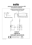
ANALOG ABSOLUTE OR INCREMENTAL POSITIONER WITH TOTALIZER
PROGRAMMABLE IN COUNTER OF REPETITIONS OR PIECES
COUNTER.
b
L1
548H05
rEL
L2
MENÚ
7
MAN
FUNZ.
El ect roni c In str um en t
F
HB 548.05
1
2
3
4
5
6
7
8
9
0
User's Manual
Enclosed to the "Manual of Set-up, Maintenance and Assistance"
This product is an electronic instrument and is thus not to be considered as a machine.
Consequently, it is not subject to the requirements stated in EEC Directive 89/392 (Machines
Directive). It is hereby specified that, if the QEM instrument is used as a component part of
a machine, it must not be switched on if the machine does not comply with the Machines
Directive.
The instrument mark does not absolve the Customer fromthe fulfilment of his or her
legal obligations regarding the finished product.
HB 548.05
INDEX OF SUBJECTS IN THIS MANUAL
CHAP. 1 - INTRODUCTION
-
Complementary feature
References1 - 2
Responsibility and validity
Description of operation
1-1
1-3
1-4
CHAP. 2 - INTERFACE OPERATOR / MACHINE
- Description keyboard
- Description inputs
- Description outputs
2-1
2-2
2-3
CHAP. 3 - STARTUP
- Programming (set-up)
- Calibrations
3-1
3-2
CHAP. 4 - USE
- Programs of work and auxiliary functions
- Tables and diagrams of operation
4-1
4-2
CHAP. 5 - ASSISTANCE
- Diagnostic of inputs and outputs
- Instructions to fill up the fax for technical assistance
- Guarantee
5-1
5-2
5-3
Pag. 1 of 47
HB 548.05
CHAPTER 1
INTRODUCTION
Complementary Features
References
Responsibility and validity
Description of operation
Pag. 2 of 47
HB 548.05
1 - 1 COMPLEMENTARY
FEATURES
This manual is to be considered as a complement to the "Manual of setup, maintenance and assistance" which
provides the instructions for the performance of wirings, troubleshooting, procedures for startup and maintenance.
This manual contains instructions for the instrument's use and or a correct programming.
We recommend then to read it carefully and, in case of misunderstanding, please contact QEM for any further
instruction by sending the assistance fax which you shall find enclosed to the manual.
1 - 2 REFERENCES
The documentation concerning the instruments designed and sold by QEM has been divided into leaflets in order to
allow an effective and quick reading according to the information required.
User's Manual
Hardware Structure
Manual of set-up
maintenance and assistance
Explanation of the described software
Basic information concerning the
series hardware and possibility of
customization.
All necessary instructions for set-up,
maintenance and assistance
It is this manual, which shows all
instructions to understand and use
the instrument described. It is a
manual concerning the software of
the instrument; it shows the
instructions to understand,
program,calibrate and use the
instrument described.
Once you install the instrument
following all indications showed on
the Manual of set-up, maintenance
and assistance, with this User's
manual, you are supplied with all
necessary instructions for the correct
use of the instrument and its
programming.
A leaflet enclosed to this user's
manual, which describes the hardware configuration concerning the
series of the described instrument.
It also shows the electric, technical
and mechanical characteristics of
the series and the possible hardware
customizations according to the software version.
Deep knowledge of all necessary
subjects for a correct set-up and
maintenance.
This is made to allow us to provide
you with most valid and safe
instructions which shall allow you to
perform products with a recognized
quality and a safe reliability.
It also provides a valid support to all
people who must face a technical
asisstance on an application
including a QEM's instrument.
Pag. 3 of 47
HB 548.05
1 - 3 RESPONSIBILITY AND VALIDITY
RESPONSiBILITY
The firm QEM is free from any responsibility for damages to people or things due to the non observance of instructions
and prescriptions contained in this manual and in the "Manual of set-up, maintenance and assistance". We also state
that the customer/purchaser must use the instrument according to the instructions supplied by QEM and in case of
doubt it must provide a written application to the firm QEM. Each authorization of use as a replacement shall be
deemed as valida by QEM, in case of contestation, only if it has been written by QEM.
It is not allowed the reproduction or the delivery to third parties of this manual or of any of its parts without a prior written
authorization made by QEM. Each infraction shall start a request of indemnization for the damages which QEM
undergoes.
All rights on patents and models are reserved.
QEM reserves the right to partially or totally modify the characteristics of the instrument described and the
documentation enclosed.
Purpose
The purpose of this manual is to show the general rules for the use of the instrument described.
Instruction
Write down and carefully store all parameters concerning the setting and programming of the instrument to the purpose
of making easier eventual operations of spare parts replacement and assistance.
VALIDITY
This manual is valid for all instruments designed, manufactured and tested by QEM with the same ordering code.
This document is integrally valid, except in case of errors or omissions.
Release of
instrument
Release
of manual
7
0
Modifications made to the manual
New manual
Date of
modifications
06 / 11 / 96
Pag. 4 of 47
HB 548.05
1 - 4 DESCRIPTION OF OPERATION
The instrument HB 548.05 is an analog positioner operating on positive and negative levels, with the possibility to set
the type of positioning (absolute or incremental). The memory can be configurated by the operator in groups of paces
(max. 255) which determine the number of programs available. To each pace can be associated (if enabled) a totalizer
which can be configurated as pieces counter or counter of repetitions of the level in use. The restart, the zero setting
of the count, the increment of pace, may be configurated so that their operation is automatic or managed by inputs.
It has a series of manual functions (introduction of a value on the count, manual movements, etc...) to make easy
the phases of calibration and to allow to the operator to operate on the positioning system.
It also has a function which allows to perform shifts to the level of delta (∆), useful for example in the management
of a small saw, for the shift of the mobile response during the cutting operation.
The instrument is adapted to an extreme variety of applications; it can manage, for example, axes with linear or circular
movements, unwindings and cutting of materials, rotating tables, etc..
Pag. 5 of 47
HB 548.05
CHAPTER 2
INTERFACE
OPERATOR / MACHINE
Description of keyboard
Description of inputs
Description of outputs
Pag. 6 of 47
HB 548.05
2 - 1 KEYBOARD DESCRIPTION
Key
0
÷
Function
9
Normal Operation: when pressed after the key "F" they select the functions available.
Data entering: they allow the data entering.
Normal operation: it selects the displayings of cycle. If pressed immediately it selects the
following displaying. If pressed in a continuous way, it selects the previous displaying.
Data entering: scroll of the various parameters. If pressed immediately it selects the following
parameter. If pressed in a continuous way, it selects the previous parameter.
Normal operation: it allows the access to the writing of the programs of work.
Data entering: it introduces or removes the sign +/-.
Normal operation: if there is no positioning in progress it allows the access to the manual
functions: manual movements, introduction of a value on the count, positioning at an
immediate level and search of the level of preset. It modifies the operation of the inputs I7 and
I8 in jog dx and jog sx.
Data entering: it introduces the decimal point.
Normal operation: if there is no positioning in progress it allows to select the functions
available.
Data entering: in the writing of the programs of work i tallows to enter the end of program. It
also allows the output from the selectable functions with the key "F" + "numeric key".
F
Data entering: it erases the entered value suggesting again the old value.
Normal operation: if enabled in set-up it controls the start to the level in execution (manual
operation only).
Data entering: it stores in memory the data introduced.
L1
Not used.
L2
Not used.
It goes On when pressing the key "MENÙ".
ME NÚ
It goes On when pressing the key "MAN".
MAN
It goes On when pressing the key "F".
FU NZ.
F
+
0
Access to the functions protected by password.
F
+
1
Choice of the program to place in execution.
F
+
2
Choice of the pace to place in execution.
F
+
3
Introduction of the blade thickness.
Pag. 7 of 47
HB 548.05
Key
Function
F
+
4
F
+
5
F
+
6
Setting the override in percentage (%).
Setting level ∆ (+, -).
Diagnostic inputs and outputs.
Pag. 8 of 47
HB 548.05
2 - 2 DESCRIPTION INPUTS
Carachteristics of inputs
Please refer to the chapter "Electric characteristics" of the leaflet " Hardware Structure" enclosed to this manual.
Logic status of
activation
Name
Way of activation
Polarizer
Description
I1
ON
I
P1
Start. it controls the positioning to the selected level. If the positioning is interrupted with a stop, with an
emergency or with the switching OFF of the instrument, the activation of input I1 restarts the positioning from
the point in which it was interrupted.
I2
ON
I
P1
Stop. Its activation brings to zero with ramp of deceleration the analog reference supplied by the instrument
interrupting the positioning.
I3
OFF
C
P1
Emergency. Its disactivation brings to a zero (with no ramp of deceleration) the analog reference supplied
by the instrument locking up the positioning. In these conditions the instrument does not get any signal for
the movement and the axis is not reacted: it is then possible to move it and the instrument shall not contrast
its movement.
I4
ON
I
P1
Restart. Its reading is enabled when there is not in execution a positioning. During the manual procedures,
the input is not enabled. It aborts the program in progress and suggests again the first pace of the program.
It sends to zero the totalizer and if in set-up the parameter "Ar" is set to "1", at each restart the calculation
is set to zero.
I5
ON
I
P1
Setting to zero the totalizer. its operation is enabled with the parameter of set-up "At" set to "1". It sets to
zero the number of pieces or repetitions counted.
I6
ON / OFF
I
P1
Enabling zero impulse. Its operation is defined by the type of "Search of preset" set in the set-up; upon its
activayion it is enabled the reading of the impulse of zero of the transducer for the loading of the level of preset.
Legend
C = Continuous Signal.
I = Impulsive Signal.
Pag. 9 of 47
HB 548.05
Name
Description
Vac
Voltage of power supply of instrument. Alternated voltage according to the code fo your order.
Vac
Voltage of power supply of instrument. Alternated voltage according to the code fo your order
GND
Ground conenction. We recommend a conductor of Ø 4 mm.
+
Positivo transducers' power supply. Positive of voltage supplied by the instrument for the supply of the inputs of instrument and
transducers.
-
Negative of power supply transducers. Negative of voltage supplied by the instrument for the supply of inputs and transducers.
INPUTS OF COUNT
Logic of
operation
Name
Polarizer
Description
PHA
N/P
PE
Input "phase A" incremental transducer.
PHB
N/P
PE
Input "phase B" incremental transducer.
Z
N/P
PE
Input "zero impulse" incremental transducer. If the parameter of set-up "tP" is set to "0", the input Z is in interruption
(immediate acquirement). If "tP" is set to "1", the input Z has a minimum time of activation of 50 milliseconds.
For the characteristics of inputs of count please refer to chapter "Electric Characteristics" of the leaflet
"Hardware Structure " enclosed to this manual.
Legend
N = Transducer with logic NPN.
P = Transducer with logic PNP.
Pag. 10 of 47
HB 548.05
Characteristics of expansion of inputs (option E)
Please refer to the chapter "Electric Characteristics" of the leaflet "Hardware Structure" enclosed to this manual.
Logic status
of activation
Name
Ways of
activation
Polarizer
Description
I7
ON
I/C
P2
Pace Increment. It increments the pace in execution if the instrument is not performing a positioning. Its
operation is enabled if the parameter of set-up "IP" is set to "0". With the output U6 = ON, it controls the
manual forward movement of the axis.
I8
ON
I/C
P2
Totalizer Increment. It increments the totalizer which can be configurated as pieces counter or counter of
repetitions. Its operation is enabled if the parameter of set-up "At" is set to "1" and the parameter "IC" is set
to "0". With the output U6 = ON, it controls the manual backwards movement of the axis.
I9
ON
I
P2
Search preset. It controls the procedures of search preset (see dedicated pragraph). Its reading is enabled
if the parameter of set-up "tP" is set to "0" and the instrument is not performing a positioning.
I10
ON
I
P2
Return to zero / Level of ∆ . Its reading is enabled if the instrument is not performing a positioning. With the
parameter "∆I10" set to "0" (function "F + 5") it controls the return to the level of zero with the speed of work.
With the parameter "∆I10" ≠ 0, it is enabled only with absolute positioning (parameter of set-up "tP" set to
"0") and it controls the positioning to the level: "level in execution + ∆I10". In this positioning it is not enabled
the recovery of clearances and the output of tolerance. If the input I10 is activated, with an automatic
increment of pace and with the parameter "∆I10" ≠ "0", at the end of the pace, the level in execution to which
is added the value of "∆I10" is that of the following pace.
N.B. With the use of input I10 it is not possible to use the start as pieces counter.
Legend
C = Continuous Signal.
I = Impulsive Signal.
Pag. 11 of 47
HB 548.05
2 - 3 OUTPUTS
Characteristics of outputs
Please refer to chapter "Electric Characteristics" of the leaflet "Hardware Structure " enclosed to this manual.
Logic status of
activation
Name
Polarizer
Ways of activation
Description
U1
ON
C1
X
Tolerance. It shows that the positioning has been achieved correctly and then within the limits set with the
parameter of set-up "Tolerance". Its energising can be delayed by the parameter of set-up "tt". Energised
for a minimum of 100 milliseconds.
U2
ON
C1
X
End of pace. It is activated when the totalizer reaches the programmed value. If the totalizer is excluded,
it is energised at the same time at the output of tolerance. It is de-energised at a pace increment (automatic
or from input) or at a restart. It is energised for a minimum of 100 milliseconds.
U3
ON
C1
X
End of program. It is energised at the end of the cyclr of work and once it is achieved the execution of alla
paces of program (and of its repetitions); it is de-energised at a restart. Energised for a minimum of 100
milliseconds.
U4
ON
C1
C
Search of preset OK. It is enabled only with absolute positioning , it is energised at the end of a search of
preset and it is de-energised at each new restart of the instrument.
U5
ON
C1
C
Error of followup. In order to position, the instrument generates an ideal profile of the positioning (ramp of
acceleration, tract at constant speed, ramp of deceleration). If the difference from the real position of the axis
from the ideal profile exceeds the value set in set-up "Error of followup", it is energised this output to signal
the malfunction.
Legenda
C = Continuous signal.
X = See description.
Pag. 12 of 47
HB 548.05
Characteristics of expansion in outputs (opzione E)
Please refer to the chapter "Electric Characteristics " of the leaflet "Hardware Structure" enclosed to this manual.
Logical status of
Activation
Name
Ways of activation
Polarizer
Description
U6
ON
C2
C
Manual. It signals that the mode of manual operation of the instrument has been selected (MAN key has
been pressed).
ON = Manual Operation , OFF = Automatic Operation.
It disables the operation of the inputs I7 (pace increment) and I8 (totalizer increment) to enable their operation
as " manual forward" (I7) and "manual backward" (I8).
U7
ON
C2
C
Enabling axis. It is energised upon the disactivation of the emrgency (I3 = ON); it is disactivated after 300
milliseconds from the activation of the emergency (I3 = OFF).
Legend
C = Continuous Signal.
Characteristics of serial RS 232C
Please refer to the chapter "Electric Characteristicsc" of the leaflet "Hardware Structure" enclosed to this manual.
Name
Description
RX
Input reception instruments.
TX
Output transmission instrument
GND
Tank connector with 9 poles, male for serial
connection.
Common of serial connection.
Pag. 13 of 47
HB 548.05
CHAPTER 3
STARTUP
Programming (set-up)
Calibration
Pag. 14 of 47
HB 548.05
3 - 1 SET-UP
These parameters determine the way of operation of the instrument and therefore their access is reserved to the
installer; for the programming we foresse to enter a password as follows:
Description
Keyboard
Access to the programming of the set-up.
F
+
0
Displaying
PASS
H ...
FU NZ.
Enter the access code "548" and confirm with ENTER.
It is possible to exit in any moment from the entering of the password
pressing the key F.
FUNCTION
Hd
4
= ON
8
F
DISPLAY
SEt UP
Mode of
displaying
5
0
DESCRIPTION
0 = Normal Displaying.
0
1 = Displaying with system HDR (High definition reading).
N.B. Please refer to the "Manual of set-up, maintenance ed
assistance".
SEt UP
Decimal digits
FP
0
SEt UP
F E 4000 00
Encoder resolution
It specifies the number of digits after the coma (max. 3), with
which you wish to display the calculation (position of axis).
N.B. The introduction of the number of decimal digits conditions
the DISPLAYING of the count; the precision of the
positionings depends upon the number of impulses supplied
by the transducer.
This parameter indicates by how much you must multiply the turn
impulses of the encoder to provide the displaying of the lenghts
in the desired units of measure. you may enter values from
0.00200 to 4.00000 upon consideration that the frequence of the
phases PH must not exceed the maximum frequence of count of
the instrument.
N.B. Please refer to the "Manual of set-up, maintenance ed
assistance".
Unit of the
speed
U
SEt UP
0
It specifies whether the unit of measure (Um) of the speed of
shifting in the axis is in minutes or in seconds (e.g. mm/minute,
mm/second, ...).
0 = Um / min.
1 = Um / sec.
Pag. 15 of 47
HB 548.05
FUNCTION
Maximum Speed
Max. 9999
Speed
of work
Speed of ∆
return to zero
Manual Speed
Manual Speed
slow
Wait of
operation
with
manual
shifting
Acceleration
Max. 9.99
Deceleration
Max. 9.99
Error
of follow up
Max. 9999
DISPLAY
DESCRIPTION
SEt UP
With this parameter is set the maximum speed of the axis, related
then to the analog reference of +/- 10 V; the value is always
referred to the unit of measure which is set (um/min. o um/sec.).
N.B. The calculaiton of this parameter MUST be made by following
the instructions shown in the paragraph "Calibration of
analog axis".
SEt UP
With this parameter is set the speed of the axis in the positioningsof
work; the value is always referred to the unit of measure which is
set (um/min. - um/sec.) and must be lower or equal to the
maximum speed.
SEt UP
With this parameter is set the speed of the axis in the positionings
at "Level +delta" or of return to zero (positionings commanded
from the input I10); the value is always referred to the unit of
measure which is set (um/min. - um/sec.) and must be lower or
equal to the maximum speed.
SEt UP
With this parameter is set the speed of the axis in the manual
shiftings; the value is always referred to the unit of measure which
is set (um/min. - um/sec.) and it must be lower or equal to the
maximum speed.
SEt UP
With this parameter is set the speed of the axis in the slow manual
shiftings; the value is always referred to the unit of measure which
is set (um/min. - um/sec.) and it must be lower or equal to the
manual speed.
SEt UP
0 = The manual shiftings are with control of reaction.
The instrument contrasts each shifting of the from the level
reached which may be caused by the outside (offset, operator,
...).
SA
SL
Sd
Sn
Sb
3456
3456
1234
3456
9990
MM
0
1 = The manual shifting has no control of reaction.
The axis can be dragged and the position is not recovered.
A
d
SEt UP
With this parameter you set the ramp of acceleration of the axis;
the value which is set determines the time employedby the axis
to go from the stop to the speed of work.
SEt UP
It determines the time in seconds of the axis, necessary to
decelerate from the speed of work to zero.
SEt UP
To manage a shifting of the axis, the instrument generates an
ideal profile of the positioning. The error of followup is the
maximum difference acceptable between the position reached
by the axis and the position which it should have reached, besides
which is isgnalled the error of followup (U5 = ON). The value
introduced is in primary impulses of encoder multiplied by × 4.
999
999
EI
9990
Pag. 16 of 47
HB 548.05
FUNCTION
Maximum Level
Max. 999999
Minimum Level
Min. -999999
S
r
t
DISPLAY
DESCRIPTION
SEt UP
It is the maximum level which can be reached by the axis; the
value whic is set is to be considered also as a maximum limit for
the introduction of the levels of work. In the case of positioning
with recovery of clearances backwards, the maximum level which
is set should be able to be exceeded by the ultralevel.
SEt UP
It is the minimum level which can be reached by the axis; the value
whic is set is to be considered also as a minimum limit for the
introduction of the levels of work. In the case of positioning with
recovery of clearances forward, the minimum level which is set
should be able to be exceeded by the ultralevel.
SEt UP
It is the area of count around all levels of positioning which
identifies the zones within which the positioning has been correctly
achieved.
Ex. Level 100.0 and tolerance 1.00; all positionings achieved
between 101.0 and 99.0 are to be considered as correct.
123456
123456
9 9 99
Tolerance
Max. 999.9
Function
key ENTER
This parameter has always a decimal digit more than what is
programmed in the parameter "Decimal digits" to allow the
operation of the QPS (QEM POSITIONING SYSTEM).
N.B. Please refer to the "Manual of set-up, maintenance ed
assistance".
E
SEt UP
0
0 = During the choice of the pace to be placed in execution, the key
ENTER confirms the pace chosen without startin gthe axis.
1 = During the choice of the pace to be placed in execution, the key
ENTER commands the positioning at the chosen pace (if the
input I1 = ON).
This displaying appears if the parameter "Function key ENTER" is set to 1
Time of verification
key ENTER
Max. 9.99
Enabling
waiting time for
reaction of space
SEt UP
It is the time, expressed•s in seconds, of activation of the key
ENTER to place in execution the pace selected.
SEt UP
0 = Disabled. The axis is always in reaction of space.
tE
999
AS
0
1 = Enabled. At the end of a positioning a time is started
(programmable with the parameter "tS") after which the axis
is not in reaction of space anymore.
This displaying appears if the parameter "Enabling waiting time of reaction of space" is set to 1
Waiting time
to enable
the control
of reaction of space
Max. 9.99
SEt UP
tS
100
It is the waiting time, expressed in secons, besides which, after
a positioning, a stop, an emergency, the control of reaction of
space is disabled and then the axis is free to be dragged with no
need for the instrument to contrast the movement trying to
recover the position.
Pag. 17 of 47
HB 548.05
FUNCTION
DISPLAY
SEt UP
rG
DESCRIPTION
0 = Positioning with no recovery of clearances.
0
Choice of
clearances
recovery
1 = Positioning with forward recovery of clearances.
2 = Positioning with backwards recovery of clearances.
N.B. Please refer to the "Manual of set-up, maintenance and
assistance".
This displaying appears if the parameter "Choice of recovery of clearances" is set to 1 or 2
Ultralevel for
recovery of
clearances,
∆ minimum
positioning
Min. 0.1
Max. 9999
Time of
inversion
Max. 9.99
SEt UP
OA
SEt UP
To avoid possible mechanical stress, two to a too fast inversion
in the direction of movement of the axis, you can enter a delay time
of inversion expressed in seconds. This parameter conditions the
operation only in case of positionings with recovery of clearances.
SEt UP
If you wish to compensate the thickness of the material removed
with the cutting, you must enable the introduction of the blade
thickness. In this case, to set the thickness of the blade, during the
normal operation of the instrument, press the keys "F + 3".
tI
AL
Enabling
blade thickness
0
During the forward recovery of clearances the axis is positioned
at: (level set-ultralevel) and, after the inversion time, it is positioned
at the level which is set.
During the backwards recovery of clearances the axis is first
positioned at: (level set+ ultralevel) and, after the invesrion time,
it is at the level which is set. If there is no recovery of clearances
or the positioning does not need recovery of clearances, and the
space to run is smaller than the ultralevel, the instrument performs
the positioning with the recovery of clearances.
100
0
0 = The blade thickness is not enabled.
1 = The blade thickness is enabled.
Pag. 18 of 47
HB 548.05
FUNCTION
DISPLAY
DESCRIPTION
Delay time of
activation
of tolerance
Max. 9.999
SEt UP
Delay time, expressed in seconds, of activation in the output of
tolerance when the axis enters the area of tolerance. By introducing the value "0" the activation of the output is immediate.
SEt UP
0 = The totalizer (count of the processings performed) is not
enabled.
Enabling
totalizer
tt
10 0 0
At
0
1 = The totalizer (count of the processings performed) is enabled.
SEt UP
IP
0
The increment pace allows to place in execution the scheduled
processings in the pace following the one in use.
The increment pace can be managed by an external signal to the
instrument (operator, PLC, ...) or by the instrument itself; in this
case, the increment pace is only managed to the purpose of the
pace in use.
0 = The increment pace is managed from the input I7.
1 = The increment pace is managed automatically by the
instrument. If the input I10 is activated, with an automatic
increment of pace and with the parameter "dELtA" (function "F
+ 5") ≠ 0, to the purpose of the pace, the level in execution to
which is added the value "dELtA", is that of the following pace.
Pace
Increment
N.B. If the instrument is not used with the expansion inputs /
outputs, this parameter must be set to "1".
With automatic increment of pace, to place in execution the
first pace of program you must provide 2 times the restart.
Delay time of start
activation
Max. 9.99
SEt UP
tQ
99 9
With this parameter it is possible to set a delay start time of the
axis from the start moment, from an input or from the key ENTER
(if the parameter "E" is set to "1"); the output of tolerance is deenergised at the command of start.
This displaying appears if the parameter "Enabling totalizer" is set to 1
Setting to zero
the totalizer
SEt UP
to
0
0 = The totalizer (count of the processings performed) is set to
zero upon activation of the input I5.
1 = The totalizer (count of the processings performed) is set to
zero upon activation of the input I5 and upon restart.
Pag. 19 of 47
HB 548.05
FUNCTION
DISPLAY
DESCRIPTION
SEt UP
It states the number of paces which make up a program. In total
there are 255 paces; by dividing then the number of available
paces by the value introduced (number of paces per program),
you obtain the number of usable programs.
Example:
Cn
0
Configuration
of memory
Max. 255
Cn
Nº of programs
= 10
= 255 / 10 = 25
The remaining paces from the division shall be added to the last
program which has in this case a size of 15 paces.
N.B. Upon each variation of the "memory configuration", the data
introduced must be written again.
SEt UP
tP
0
0 = Absolute Positioning. With the choice of this type of
positioning the totalizer, if enabled, becomes a pieces counter.
1 =Incremental Positioning. With the choice of this type of
positioning the totalizer, if enabled, can become a pieces
counter or a counter of repetitions of the level. The procedure
of search level of preset is not enabled. Furthermore, the input
Z becomes a loading preset which can be used to set to zero
or substract the calculation.
Choice of type
of positioning
2 = Incremental Positioning with setting to zero count. With
the choice of this type of positioning the totalizer becomes a
counter of repetitions of the level. The procedure of search
level of preset is not enabled. Furthermore, the input Z can be
used to set to zero or substract the calculation (parameter "CA"
set to "0").
N.B. Please refer to the chapter "Tables and diagrams of
operation".
Please refer to the "Manual of set-up, maintenance and
assistance".
Pag. 20 of 47
HB 548.05
FUNCTION
DISPLAY
DESCRIPTION
These displayings appear if the parameter "Choice of type of positioning" is set to 0
SEt UP
bP
The procedure of search of preset is performed:
0
0 = Loading on the count the level of preset upon the disactivation
of the input I6.
1 = Loading on the count the level of preset upon activation of the
input Z after that the axis has inverted the direction and the
input I6 has been disactivated (sensitive to the descent front).
2 = Loading on the count the level of preset upon activation of the
input Z after that the input I6 = ON (impulsive).
Preset
Loading
3 = It is not enabled the procedure of preset search.
Upon activation of the input I6, the level of preset is loaded on
the count.
N.B. See dedicated paragraph.
Please refer to the "Manual of set-up, maintenance and
assistance".
Speed of preset
Speed of search
after the enabling
of the zero
impulse
Level of preset
SEt UP
With this parameter you set the speed of the axis for the search
of the input of enabling; the value is always referred to the unit of
measure which is set (um/min. - um/sec.) and it must be lower or
equal to the maximum speed.
SEt UP
With this parameter you set the speed of the axis after the
activation of the input of enabling; the value is always referred to
the unit of measure which is set (um/min. - um/sec.) and it must
be lower or equal to the speed of preset.
We suggest to use very low values.
SEt UP
In the procedure of search of preset, it is the level that is loaded
on the count with the zero impulse of the transducer (according
to the way defined by the type of search of preset). It is possible
to enter a level of preset included between maximum level and
minimum level.
SP
UP
P
3456
1234
123480
This displaying appears if the parameter "Enabling totalizer" is set to 1
Increment of
pieces counter
SEt UP
tO
0
0 = The increment pieces counter is associated to the input I8
(increment of totalizer).
1 = The increment pieces counter is associated to the input of start
(when the axis has reached the selected level).
Pag. 21 of 47
HB 548.05
FUNCTION
DISPLAY
DESCRIPTION
ALL THE FOLLOWING DISPLAYINGS APPEAR IF THE PARAMETER "CHOICE OF TYPE OF POSITIONING" IS SET TO 1 OR 2.
This displaying appears if the parameter "Choice of type of positioning" is set to 1
SEt UP
Ft
0
Operation of the
totalizer
0 = The totalizer (count of the processings performed) is managed
as a pieces counter incrementable from the input I8.
When the axis reaches the level which is set, it remains in the
position reached until all processings which have been set are
performed.
1 = The totalizer (count of the processings performed) is managed
as a counter of repetitions incrementable from the input I8. A
processing is made up of a positioning at the level which has
been set; the axis repeats the positioning until all processings
which have been set are performed.
This displaying appears only if the parameter "Operation of totalizer" is set to 1 and the parameter "Choice of type of positioning" is
set to 1. it also appears in case the parameter "Choice of type of positioning" is set to 2
Increment of
counter of
repetitions
SEt UP
IC
0
0 = The increment of the counter of repetitions is associated to the
input I8 (increment of totalizer).
1 = The increment of the counter of repetitions is associated to the
input of start (when the axis has reached the level selected).
SEt UP
tC
0 = The calculation is set to zero.
0
1 = The calculation is updated to the level of preset.
2 = The calculation is set to zero by substracting the value of the
count reached to the level of positioning performed (which is
used not to lose the absolute position in the angle shiftings).
Example:
Type of
setting to zero
the count
Set-point = 360
Count
= 359; after setting to zero count = -1
N.B. With the parameter "tP" set to "1" the zero setting of the
count can be performed only by activating the input Z.
This displaying appears if the parameter "Type of setting to zero count" is set to 1
Level of preset
P
SEt UP
123480
It is the value that is loaded on the count when you activate the
command of setting to zero (CA). It is possible to enter a level of
preset included between the maximum and the minimum level.
Pag. 22 of 47
HB 548.05
FUNCTION
DISPLAY
DESCRIPTION
This displaying appears if the parameter "Choice type of positioning" is set to 2
SEt UP
CA
0
1 = The command of setting to zero is performed automatically
upon activation of the start (I1) after the end of a positioning.
Command of
setting to zero
Setting to zero
the count
upon restart
0 = The command of setting to zero is performed through the
activation of the input Z.
2 = The command of setting to zero is performed automatically
upon activation of the start (I1) after the end of a positioning;
furthermore the input sets to zero the calculation indipendentely
from the parameter "tC" (type of setting to zero count).
SEt UP
Ar
0 = Upon restart the calculation is not set to zero.
0
1 = Upon restart the calculation is set to zero with the ways which
have been set in the parameter "tC" (type of setting to zero
count).
This displaying appears for all types of positioning
Enabling
the seriale RS
232C
SEt UP
rS
0 = The serial RS 232C is disabled.
0
1 = The serial RS 232C is enabled.
This displaying appears if the parameter "Enabling RS 232C" is set to 1
SEt UP
Speed of
transmission
RS 232C
Number of data bits
Number of stop bits
br
4800
SEt UP
db
SEt UP
Sb
SEt UP
PA
7
2
110
150
300
600
1200
2400
4800
9600
baud
baud
baud
baud
baud
baud
baud
baud
7 bits
8 bits
Speed of transmission available; if the speed is
wrong, accepting and displaying the wrong value,
by default it is stored in memory the value 9600.
Number of data bits; if the number of bits is wrong, the
instrument takes as default the value 8.
1 bit of stop
2 bit of stop
Number of stop bits; if the number of bits is
wrong, the instrument takes as a default the
value 2.
0 = No parity.
0
1 = Odd parity.
Parity bits
2 = Pair parity.
Value of default "0".
Pag. 23 of 47
HB 548.05
FUNCTION
Code of
address
Enabling
chksum
DISPLAY
DESCRIPTION
SEt UP
In case of connection of various instruments with Daisy-Chain
configuration, it is necessary to assign to each instrument an
identificative code. In case of a transmission from master with
code "00", the string which is sent is received by all instruments.
SEt UP
0 = The chksum of the data transmitted is not enabled. Before
sending another character, the instrument awaits from the PC
the echo of the charactere previously transmitted.
CI
00
CH
0
1 = The chksum of the data transmitted is enabled. It is calculated
the l'OR exclusive of the dat awhich have been sent (see
dedicated paragraph "Commands in RS 232C").
This displaying appears if the parameter "Enabling chksum" is set to 1
Transmission
delay
SEt UP
rt
999
It is the time, expressed in milliseconds, that the instrument
places between the transmission of a character and the sending
of the following character.
Once the programming of the last function is achievede, the displaying of the first parameter of set-up appears again.
Pag. 24 of 47
HB 548.05
3 - 2 TARATURE
PROCEDURE OF CALIBRATION OF ANALOG OUTPUT
Setting some parameters of set-up.
You must set in set-up the parameters related to decimal digits, transducer's resolution, unit of speed.
Description
Access to the procedure of calibration
Activate the input of emergency (I3 = ON).
Enter the password "123".
Keyboard
F
1
0
+
2
Displaying
PASS
H ...
0
3
By the double arrow key it is possible to select three differemt
displayings: "tu" (voltage of output), "OF" (offset count) "GA" (ring
gain).
tu
0F
000
00
345
123
123456
GA
Verification of connections
The first thing to verify is the exact conenction of the tachometer
dynamo upon the startup. Select the displaying related to the
"Voltage of output (tu)" and enter via the numeric keyboard a
value of voltage, confirming it with the key ENTER. We suggest
to enter a quite low value of voltage (e.g. 0.5 V) and to observe
if the motore runs at apx. 1 / 20 of its maximum speed (if the
drive accepts a maximum voltage of 10V).
Supplying a positive voltage from the keyboard, the motor must run
"forward" with a speed being proportional ot the value introduced,
and the calculation displayed must be increased.
N.B. The value of voltage introduced from the keyboard is
supplied by the analog output with no rampa of
acceleration.
Calibration of the offset
Select the displaying related to the calibration of the offset "offset
in steps (OF)" and follows the indications described here below:
the operator can enter with the numeric keys and the sign, a
qualsiasi value that upon confirmation with ENTER shall be
immediately shown in output.
Calculation of the speed
The instrument is now able to calculate and display the value of the
maximum speed to be entered in set-up in the parameter "Maximum
speed (SA)".
Select the displaying related to the "voltage of output introduced
(tu)". Enter, via the numeric keyboard, a voltage of 10 volt (to which
corresponds the maximum speed of the motor).
N.B. The value of voltage introduced from the keyboard is
supplied by the analog output without ramp of acceleration.
To be continued on the following page.
tu
0
÷
÷
00
345
123
9
tu
1
000
9
0F
0
1234
000
00
0
Pag. 25 of 47
HB 548.05
Description
In case it is not possible to move the axis to the maximum speed,
enter a voltage of 1 volt. The displaying of the speed supplied by the
instrument must be then multiplied by 10.
With the axis in movement press the key MAN.
On the upper display is displayed the frequency of count (detected
on the phases of the encoder). On the lower display it is displayed
the value of the maximum speed to enter in set-up in the parameter
"Maximum speed".
It is possible, in this displaying, to enter a filter on the displaying
keeping pressed the key ENTER.
Keyboard
Displaying
F
UL
12345
9876
Complete the programming of the set-up
Calibration of the gain
Select the displaying related to the "Ring gain (GA)". This allows to
quickly adapt the positioner to the sensitivity of input in the drive. the
bigger is the value of the ring gain, the greater is the readiness
with which the axis moves but obviously the greater is the
instability of the system.
123456
GA
1234
Pag. 26 of 47
HB 548.05
CHAPTER 4
USE
Programs of work and auxiliary functions
Tables and diagrams of operation
Pag. 27 of 47
HB 548.05
4 - 1 PROGRAMS OF WORK AND AUXILIARY FUNCTIONS
INTRODUCTION OF THE PROGRAMS OF WORK
The program of work is made up of a certain number of paces, defined with the parameter of set-up "Memory
Configuration".
For each pace it is possible to set a level of positioning (preselection) and the number of processings to make once
the level which has been set is reached (totalizer).
Description
Keyboard
Displaying
Pr o Gr
Access to the writing of the programs of work.
n r1 1 2
Select the desired program confirming it with ENTER (the number
of the pace in phase of programming is displayed on the lower left
display).
On the upper line it is displayed the level of positioning (blinking).
The operator can enter the desired level and confirm it with the key
ENTER.
Upon confirmation of the level of positioning, the line of the display
on the down right corner starts to blink for the introduction of the
totalizer (number of processings to perform at the level which has
been set); the operator can enter the number of desired processings
and confirm it with the key ENTER.
Upon confirmation of the totalizer it is required to enter th eend of
program; if the operator decides to continue he must confirm with
ENTER.
It is then proposed the second pace of the selected program.
The operator has the possibility to enter the level and the totalizer
in the case of the second pace.
Upon confirmation of the totalizer it is required to enter the end of
program; if the operator decides to continue he must confirm with
ENTER; if this is not the case, press the key F to enter the end of
program, confirming it with ENTER.
To exit the writing of the programs, press the key MENÙ.
It is possible to exit in any momento the programs' introduction; only
those values confirmed with ENTER shall be stored in memory.
0
÷
9
0
÷
9
0
÷
9
MENÚ
= ON
123456
1
1234
123456
2
1234
F
ME NÚ
= OFF
Pag. 28 of 47
HB 548.05
CHOICE OF THE WORKING PROGRAM TO BE EXECUTED
With the parameter of set-up "Memory Configuration" we have defined a certain number of programs of work,
containing each a set of paces made of level of positioning and totalizer. For the choice of the program to be placed
in execution, please follow these instructions:
Description
Access to the function of program choice .
Keyboard
F
Displaying
SCEL t A
1
+
P r1 0 1
FU NZ.
Enter the number of the desired program, confirming it with ENTER.
Upon confirmation with ENTER of the number of program, the
instrument requires the number of times that the program selected
must be repeated before signalling the end of the program (number
of cycles).
The operator must then enter the number of repetitions of the
program (1÷999). If you set the value 999, the calculation of the
cycles is disabled and then the program is repeated "continuously".
The choice of a program completely aborts the execution of the
program which was previously in use.
0
÷
9
0
÷
9
= ON
CIc L I
n
401
To exit the function of program choice, press the key F.
FU NZ.
F
= OFF
CHOICE OF PACE
With the choice of the program to be placed in execution, the instrument starts the positionings from the first pace of
program. It is possible to select any pace (of the program in use) so that the execution of the program starts from the
desired pace skipping all the previous paces.
Description
Access to the function of choice of pace.
Enter the number of the pace from which you wish to start the
program and confirm with ENTER.
The execution of the program shall start with the command of axis
start. If you wish that the program starts from the beginning, it is not
necessary to perform the choice of the pace.
To exit the function of choice of program, press the key F.
Keyboard
F
0
F
2
+
÷
Displaying
SCEL t A
P S1 1 1
FU NZ.
= ON
FUNZ.
= OFF
9
Pag. 29 of 47
HB 548.05
INTRODUCTION OF THE BLADE THICKNESS
It is possible to compensate the quantity of material removed in the cutting operation by entering the thickness of the
blade in use. The value introduced shall be added to all the levels of positioning, in order to increase the thickness
of the blade.
Description
Access to the function of introduction of blade thickness.
Enter the thickness of the bladein use and confirm with ENTER.
Keyboard
F
0
3
+
Displaying
SL A M A
1 2 3 4 56
FU NZ.
= ON
FU NZ.
= OFF
9
÷
It is possible to modify the value of the blade thickness also during
the execution of a program; the new value introduced shall be used
for the remaining positionings.
To exit the function of choice of program, press the key F.
F
INTRODUCTION OF THE OVERRIDE
The override is the percentage of the speed of work which has been set in the set-up with which you must perform
the positionings. By introducing 100%, the speed of positioning is the same than the speed of work, by introducing
50%, the speed of positioning is equal to half of the speed of work etc.
By modifying the speed of work, you modify by the same percentage also all other speeds which have been set.
Keyboard
Description
Access to the function of introduction of override.
Enter the desired percentage and confirm with ENTER.
F
0
4
+
÷
Displaying
OuEr
r Id
FU NZ.
= ON
FUNZ.
= OFF
70
9
It is possible to modify the value of the override also during the
execution of a program; the new values of speed shall be used for
the remaining positionings.
To exit the function of choice of program, press the key F.
F
Pag. 30 of 47
HB 548.05
INTRODUCTION OF LEVEL OF DELTA
According to the value introduced, this parameter develops a double function: if the value introduced is zero, upon
activation of the input dedicated, the axis is located at the zero level (the axis is moved until the calculation arrives
on zero). If the level introducesd is different from zero, upon activation of the input dedicated, the axis is located at
the level of positioning plus the value introduced. This operation, which can be applied in different processings, has
been conceived for the positioning of a mobile striker for small saws: once the material has been layed against the
striker and the clamp has been closed, before th ecutting it is necessary to move the striker in order not to break the
blade. By activating the dedicated input, the striker moves at the "level of cutting + level of delta". Upon activation of
the start (if a new pace has not been put in execution), the axis returns to the level of positioning.
Description
Access to the function of introduction of level of delta.
Enter the desired gap and confirm with ENTER.
By setting the value "0", upon activation of the input I10, the axis is
located to the level of zero.
By setting a different value from "0", upon activation of the input I10,
the axis is located to the level: "level in execution + ∆".
Keyboard
F
0
5
+
÷
Displaying
dEL t A
9 9 9 9 99
FU NZ.
= ON
FUNZ.
= OFF
9
N.B. With a value of ∆ different from "0", the input I10 is enabled
only with the parameter of set-up "tQ" set to "0".
It is possible to modify the value of the level of delta also during the
execution of a program; the new value of difference shall be used
for the remaining positionings.
To exit the function of choice of program, press the key F.
F
Pag. 31 of 47
HB 548.05
MANUAL SHIFTING OF THE AXIS
The instrument offers some functions for the manual management of the axis. It is possible to move the axis from the
keyboard in the two directions and with two different speeds. once you select the manual function of axis shifting, with
the key 7 it is possible to shift the axis "backwards" (count that decreases), with the key 9 it is possible to shift the axis
"forward" (count that is decreased). With the key 8 it is possible to select the speed of manual shifting (slow or fast).
Description
Keyboard
Displaying
MAn UAL E
L
1 2 3 4 56
Access to the manual functions and selecting the displaying related
to the movement of the axis.
MA N
The lower left display shows the speed selected with the key 8 (L
= slow, F = Fast).
The displays on the lower right corner show the calculation (position
of the axis).
During the manual shifting are enabled the limits which have been
set with the minimum and maximum levels (set-up).
7
8
= ON
9
= OFF
To exit the manual functions press the key MAN.
MA N
POSITIONING AT AN IMMEDIATE LEVEL
The instrument offers some functions for the manual management of the axis. It is possible to automatically position
the axis at a level being different from the selectable levels of work which can be chosen in the introduced programs.
This function allows to remarkably speed up oall operations of positioning which are different from those of normal
processings.
Description
Keyboard
Displaying
1 2 57
Access to the manual functions and selecting the displaying related
to the introduction of the immediate level.
The upper displays show the calculation (position of the axis),
the lower displays show the level of immediate positioning introduced.
The operator can enter the desired immediate level.
Upon confirmation with ENTER of the value introduced, the
instrument locates the axis to the level introduced after the time "tQ".
4 56
0
÷
MAN
= ON
MA N
= OFF
9
To exit the manual functions press the key MAN.
Pag. 32 of 47
HB 548.05
SEARCH OF THE LEVEL OF PRESET (ENABLED ONLY WITH ABSOLUTE POSITIONING )
The instrument offers some functions for the manual management of the axis. It is possible to command the search
of the level of preset also from the keyboard (for the description of the search level of preset see the dedicated
paragraph).
Description
Keyboard
Displaying
rPr
Access to the manual functions manuali and selcting the displaying
related to the search of the level of preset.
MA N
ESEt
1 4 56
= ON
The lower displays show the value of the count.
Upon confirmation with ENTER, the calculation displayed blinks to
signal the start of the search of preset and at the same time the axis
moves to search the command of loading of the level of preset.
Once you load the level of preset on the count, the display stops
blinking to signal the end of the procedure.
F u nPr S
In the incremental positionings and incremental with setting to zero,
the search of preset is disabled. Then if in set-up the parameter "tP"
is set to "1" o "2", the instrument shall signal that the search of preset
is disabled.
di 5Ab
To exit the manual functions at the end of the procedure or to abort
the search of preset press the key MAN.
MAN
= OFF
INTRODUCTION OF A VALUE ON THE COUNT
The instrument offers some functions for the manual management of the axis. It is possible to modify the value of the
count displayed by the instrument (position of axis), by entering the desired value. This function is specially useful in
phase of setup and calibration.
Description
Keyboard
InCo
Access to the manual functions and selecting the displaying related
to the introduction of a value on the count.
The operator can enter the desired value of count.
The lower displays show the value of the count introduced.
Upon confirmation with ENTER, the instrument displays the value
introduced.
To exit the manual functions press the key MAN.
Displaying
0
÷
unt
1 4 56
MA N
= ON
MA N
= OFF
9
Pag. 33 of 47
HB 548.05
DISPLAYINGS
Description
Keyboard
Displaying
1 2 3 4 56
Display upper right corner
Count of axis.
Display lower right corner
Level in execution.
Display upper right corner
Count of totalizer.
Display down right corner
Preselection of totalizer.
If the totalizer is not enabled.
Display upper left corner
Program in use.
Display lower left corner
Pace in use.
Display upper right corner
Cycles which have been set.
Display lower right corner
Cycles made.
1 2 3 7 85
I234
t
3837
Pr
G
PS
I
5
C P1 2 3 4
C F12 34
Pag. 34 of 47
HB 548.05
If it is present on the instrument the option RS 232C and in SET-UP is enabled the serial transmission, it is possible
to transmit from a PC the control for the data writing and reading. The serial port can be configurated programming
the suitable parameters of SET-UP of the instrument.
It is possible to adjust the transmission speed, the number of data bits, the number of stop bits, parity bits, the enabling
to the control of the chksum (OR exclusive) and the code with the address of the instrument.
If it is not chosen from the set-up the control of the chksum with delay of transmission of character, the instrument
manages the echo of the character transmitted. The characters that compose the string are in hexadecimal format
(Hex.).
The numeric data are managed by bytes (two characters per byte). The instrument is always slave, and can transmit
only a request of the PC (master).
Sintaxis of general transmission control from PC to the instrument.
Each string of command sent by the PC, shall always start with the character "{" (value ascii=7B Hex.).
The first two characters are the code of address of the instrument to which is destinated the message. The following
two characters, must be two capital letters which identify the command code. The following 2 characters identify the
length expressed in bytes of the string of data which are sent or of data to read in case there is a request for reading
(you may read or write 100 bytes (Hex 64) at maximum). Follows then the operating number, i.e. the numeric value
of the variables concerned by the transmission. The strings which are sent without placing before the character "{"
and at the end of the character "@", are ignored.
In case the instrument finds a chksum different from that transmitted by the PC, the data shall not be accepted (the
malfunction can be found by performing a verification of the equal feature between the chksum of the transmitted data
and the chksum calculated by the instrument, that is sent by the same each time that is required an operation of data
writing). The instrument controls the limits of the data transmitted and the enabling to accept it. If it is not enabled the
control of the chksum, the echo received by the instrument is not controlled but used to continue the transmission of
the characters.
Command of transmission.
{ XX YY XXXX XX XX.. XX @
{
= Code of string of transmission start from PC ({).
XX
= Code of address. It identifies the instrument in transmission / reception (1 byte max.; value = 63 Hex.).
YY
= Code of command (two letters).
TS = Request of data writing .
TL = Request of data reading.
XXXX = Address of data (2 byte max.; value = FFFF Hex.).
XX
= Number of bytes transmitted or to be read (100 byte max.; value = 64 Hex.).
XX..
= String of data (it is not present in case of reading request).
XX
= Chksum of the string transmitted excluded the characters of start and end of string ({, @).
@
= Character of end of string.
Siyntaxis of general response command from instrument to PC.
The instrument, operating as a slave, shall always transmit in response to the controls sent from the PC. Each string
of response sent by the instrument, shall always start with the character "[" (value ascii=5B Hex.).
The first two characters shall be the code of address of the instrument in response to the requets to send the data made
by the PC. The following two characters, shall be two capital letters which identify the command code.
To be continued on the following page.
Pag. 35 of 47
HB 548.05
After the command code, if the PC has required the reading of a data, follows the operating number, i.e. the values
of the variables required by the PC and subsequently the two characters of chksum.
In case of response at a command of writing, after the code command, it is transmitted the chksum calculated by the
instrument (if enabled). The characters which are sent without placing before "[" and at the end the character "@", are
ignored. The chksum transmitted by the instrument, is the chksum of response to a command of writing from PC or
the chksum of the string of reading data required by thePC. If during the transmission of the instrument arrives a wrong
character of echo , the transmission itself is aborted.
Command of transmission.
[ XX YY XX...X XX @
[
= Code of string of transmission start from instrument ([).
XX
= Code of address. It identifies the instrument in transmission / reception (1 byte max.; value = 63 Hex.).
YY
= Code of command (two letters).
RS = Response to a request of writing data.
RL = Response to a request of reading data.
XX...X = Address to be read.
XX
= Chksum of the string transmitted excluded the of start and end of string ([, @), or of response to the command
of writing of the PC.
@
= Character of end of string.
Example of writing data.
In case you wish to transfer to the instrument 01, n. data having address of start "007F" and length 6 bytes, divided
into 2 bytes, for the first data and, 1 byte for the second, you only need to operate as follows:
Code of address of instrument
= 01 (Hex. 01).
Address of start
= 127 (Hex. 007F).
Number of bytes to be written
= 03 (Hex. 03).
Value to transfer of the first data
= 1234 (Hex. 04D2).
Value to transfer of the second data = 88 (Hex. 58).
CHKSUM = It is calculated performing the XOR of the bytes that compose the string to transmit, with the exclusion
of the character "{" (character of start of string) and of the character "@" (character of end string).
In this case then the string of characters must be made as follows:
{01TS007F0304D258 ... @
In the space left by the points you must enter the value of the CHKSUM of the string of characters transmitted. In this
case the value is:
CHKSUM = 30 XOR 31 XOR 54 XOR 53 XOR 30 XOR 30 XOR 37 XOR 46 XOR 30 XOR 36 XOR 30 XOR 34 XOR
44 XOR 32 XOR 35 XOR 38=0E (value Hex.).
The string of characters to transfer is then:
{03TS007F0304D2580E@
To becontinued on the following page
Pag. 36 of 47
HB 548.05
After performing the transmission of the string, you must wait for the response of the card that, in case the transmission
has been performed with no error, shall occur with the following string of characters:
[01RS0E@
Example of data reading.
In case you wish to read from the instrument, to which we give the address code of instrument "12", n. data having
the address of start "Hex. 086A" and length 4 bytes, divided into 1 byte for the first data and 3 bytes for the second,
you must operate as follows:
Code of the address of the instrument =
12 (Hex. 0C).
Address of start
= 2154 (Hex. 086A).
Number of bytes to be read = 04 (Hex. 04).
CHKSUM = It is calculated by performing the XOR of the bytes which make up the string to transmit, with the exclusion
of the character "[" (character of start of string) and of the character "@" (character of end of string).
In this case then the string of characters transmitted by the PC to require the reading of the data to the instrument,
must be made as follows:
{0CTL086A04 ... @
In the space left by the points, you must introduce the value of the CHKSUM of the string of characters transmitted.
In this case the value shall be:
CHKSUM = 30 XOR 43 XOR 54 XOR 4C XOR 30 XOR 38 XOR 36 XOR 41 XOR 30 XOR 34=10 (value Hex.).
The string of characters to transfer is then:
{0CTL086A0410@
After performing the transmission of the string, you must wait the response of the instrument that, in case the
transmission has beenmade with no erro, and the values for the dat arequired are for the first data, at a byte "37" (Hex.
25) and for the second data "123456" (Hex. 01E240), the following string of characters shall then be given:
[0CRL2501E24018@
After verifying that the value of chksum calculated on the data arrived is equal to the value of chksum transmitted by
the instrument (if this isn ot the case you must repeat the request of reading and the data arrived must not be accepted),
you can find the values of the data required by decomposing the string of characters received in this way:
[
=
Character of starting string.
0C
= Address of the instrument from which comes the response.
RL
= Code of command (response upon request of data reading).
25
= Hexadecimal value of the first data transmitted.
01E240 = Hexadecimal value of the second data transmitted.
18
= Value of chksum of the string transmitted (calculated with no consideration of characters "[" and "@").
@
= Character of end of string.
N.B. With the serial it is possible to write in the memory but not to manage the movements (manual movements, start,
stop etc.).
Pag. 37 of 47
HB 548.05
Address of data in the machine parameters.
Address of data
(in Hex.)
Length
in bytes
0000
1275
Values min-max
(in decimal)
Description of data
Memory at 76 paces each of which
occupies 5 bytes.
0000
0001
0002
0003
0004
0005
0006
0007
0008
0009
"
"
"
"
"
"
04F6
04F7
04F8
04F9
04FA
Level to perform
Pace
1
Preselect.
totalizer
of
Level to perform
Pace
2
Preselect.
totalizer
of
Level to perform
Pace
255
Preselect.
totalizer
of
Pag. 38 of 47
HB 548.05
Address of program data.
Address of
data (in Hex.)
Length
in bytes
Description of data
Values min-max
(in decimal)
0500
1
Program in execution
0501
1
Pace in execution
0502
2
Preselect. of totalizer
0504
2
Count
0506
2
Cycles set
0508
2
Cycles made
050A
2
Input
050C
1
Output
050D
3
Count of axis
Minimum Level÷ Maximum Level
0510
3
Level in execution
1÷nº paces per program
0513
3
Immediate Level
Minimum Level÷ Maximum Level
0516
3
Level DI10
-999999÷999999
0519
3
Blade thickness
-999999÷999999
051C
2
Override
1÷100
1÷
nº paces available (76)
nº paces (X) program
1÷nº paces per program
1÷9999
N.B. The instrument allows the writing of a single parameter at once allowing thus to check the size of the data.
The string of response at a command of writing can be negative in case you try to access to various
parameters at the same time or the data introduced is not included within the limit values.
Pag. 39 of 47
HB 548.05
4 - 2 TABLES AND DIAGRAMS OF OPERATION
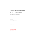
INCREMENTAL POSITIONING WITH SETTING TO ZERO COUNT AND COUNTER OF REPETITIONS
Cont.
A1
5
I1
7
2
6
I2
I3
9
11
I4
1
8
Z
4
I7
I8
U1
3
U2
U3
10
1
Upon restart it is set to zero the calculation ("Ar" = 1) and placed in await of execution the first pace of the program.
2
Upon the start (I1), the instrument generates A1 that commands the shift of the axis.
3
At the end of the positioning, it is activated the output of tolerance U1 and at the same time, by activating the input
I8, it is given an increase to the toalizer (repetitions).
4
The activation of the input Z sets to zero the calculation of the axis.
5
With a new start, the axis starts a new positioning.
6
If during the movement, the stop is activated (I2), it is commanded a braking with ramp of deceleration.
7
The positioning interrupted is ended with a new start.
To be continued on the following page
Pag. 40 of 47
HB 548.05
8
At the end of the positioning, it is activated the output of tolerance U1 and at the smae time, by activating the input
I8, it is given an increase to the totalizer (repetitions). In this case the output U2 of end of pace is activated and
the input I7 is activated, to proceed with the following pace.
9
If during a positioning, the emergency is activated (I3 = OFF), the analog output A1 is immediately brought at zero
volt and to achieve the positioning you must provide again a start (I3 = ON).
10 The new increase of totalizer, activates the output of end of program (U3) and of end of pace (U2).
11 A new restart disactivates the outputs U2 and U3, sets to zero the calculation and arranges the instrument for a
new cycle of work.
N.B. This operation has been obtained by introducing the following values in the parameters of set-up:
"rG" = 0, "tt" = 0, "At" = 1, "IP" = 0, "tP" = 1, "tC" = 0, "CA" = 0, "Ft" = 1, "IC" = 0, "Ar" = 1
Pag. 41 of 47
HB 548.05
Structure of set-up for absolute positionings
Main characteristics of absolute positionings
Count
Set-up
Pass 548
150
Mode of display
Hd
100
Decimal digits
FP
50
Choice type posit.
Set to zero
tP
50
100
150
Levels which have
been set
Preset loading
- Need to perform a search of preset totally managed by the
instrument, with start from keyboard or from input.
- Setting a field of work. With the introduction of the minimum
and maximum levels , it is defined the maximum gap of the
axis. All attempts to position the axis besides the limits
defines are made unuseful by a displaying of error.
- Management of a pieces counter. Then possibility to associate to each position to reach a certain number of processings.
bP
Preset Speed
SP
Search Speed
UP
- Levels of work referred to the zero machine.
Level of preset
P
Enab.
serial
RS
0
1
Transm.speed RS
232
br
END
Pag. 42 of 47
HB 548.05
Structure of set-up for incremental positionings
Set-up
Pass 548
Main characteristics of incremental positionings
Count
150
Mode of display.
Hd
100
Decimal digits
FP
50
Choice type posit.
Set to one
tP
50
50
50 Levels
which
have been set
- Processings a pace.
1
ft
- Levels of work not referred to the zero machine, but
to the position reached by the axis in the previous
positioning.
Increase. count.
of repet.
IC
0
1
- Possibility to associate to each level a certain number
of processings or, to set for each level introduced a
certain number of repetitions of the same.
tC
0/2
- Ideal for the optimization of the material to be cut
(iron rod, paper sheet, marble sheet, etc.) because,
if the levels are set correctly, at the end of the
processing there are no rejects or scraps.
- Various possibilities to update the calculation. The
main is the setting to zero by substraction. In this
way it is always possible to position by recovering
the eventual error of the previous positioning. As a
consequence, it is alsways possible to check the
real position of the axis avoiding thus to accumulate
the errors due to the mechanics.
Level of preset
P
Set
to
calculat.
zero
Ar
Enab.
serial
RS
0
1
Transm. speed
RS 232C
br
END
Pag. 43 of 47
HB 548.05
Structure of set-up for incremental positionings with
setting to zero
Set-up
Pass 548
Main characteristics of incremental positionings with
setting to zero
Count
Mode of display
Hd
50
Decimal digits
FP
50
50
50 Levels which
have been set
Choice type posit.
Set to two
tP
- Ideale for the management of applications
asunwinding and cutting, rotating tables, winding
machines and similar devices.
- Possibility to associate to each level a certain number
of repetitions of the same.
Increase of piece
counter
IC
- The levels of work are not referred to the zero
macchine but to the position reached by the axis in
the previous positioning.
- Variious possibilities to update the calculation. The
main is the setting to zero by substraction. In this
way it is always possible a position by recovering the
eventual error of the previous positioning. As a
consequence, it is always possible to check the real
position of the axis avoiding thus to accumulate the
errors due to the mechanics.
1
tC
0/2
Level of preset
P
Com. set to zero
CA
Count set to zero
Ar
Enab.
serial
RS
0
1
Transm. speed
RS 232C
br
END
Pag. 44 of 47
HB 548.05
PRESET SEARCH
"Modo 0" - Loading of the level of preset with the use of the input of enabling impulse of zero.
The command of loading of the level of preset is supplied only from the input of enabling impulse of zero.
Once you started the procedure of search of preset, the axis goes towards the sensor connected to the
input of enabling the impulse of zero; when, in its stroke, the axis activates this input, it inverts the direction
by slowing down.
Upon the disactivation of the input of enabling impulse of zero it is loaded the level of preset on the count
of the instrument.
With this procedure the condition for the loading of the level of preset is that the input of enabling has been
activated and then disactivated.
"Mode1" - Loading of the level of preset with the use of the zero impulse and of the input of enabling impulse
of zero with inversion.
The command of loading of the level of preset is supplied by the zero impulse of the transducer. Since
an encoder supplies an impulse of zero to each revolution, it is necessary to understand in which zone
of the axis you must get the impulse of zero; to this purpose it is used the input of enabling impulse of
zero.
Once you started the procedure of search of preset, the axis goes towards the sensor connected to the
input of enabling the impulse of zero; when, in its stroke, the axis activates this input, it inverts the direction
by slowing down.
Upon the disactivation of the input of enabling the instrument is ready to get the impulse of zero; ath the
first impulse of zero supplied by th etransducer it is loaded the level of preset on the count of the
instrument.
With this procedure the condition for the loading of the level of preset is that the input of enabling has been
activated and then disactivated and that an impulse of zero is acquired.
"Mode 2" - Loading of the level of preset with the use of the impulse of zero and of the input of enabling
impulse of zero with no inversion.
The command of loading of the level of preset is supplied by the zero impulse of the transducer. Since
an encoder supplies an impulse of zero to each revolution, it is necessary to understand in which zone
of the axis you must get the impulse of zero; to this purpose it is used the input of enabling impulse of
zero.
Once you started the procedure of search of preset, the axis goes towards the sensor connected to the
input of enabling the impulse of zero; when, in its stroke, the axis activates this input, it inverts the direction
by slowing down.
The instrument is ready to get the impulse of zero: at the first impulse of zero supplied by the transducer
it is loaded the level of preset on the count of the instrument.
With this procedure the condition for the loading of the level of preset is that the input of enabling is
activated and an impulse of zero is acquired. To avoid error it is necessary that the space of activation
of the input of enabling is smallerthan the space run by the axis with an encoder revolution. If this is not
the case, the zero impulse may be acquired in two different points.
"Mode 3" - Loading the level of preset from input.
With this procedure the search of preset is not enabled. The command of loading of the level of preset
is supplied by the activation of the input I6.
Pag. 45 of 47
HB 548.05
CHAPTER 5
ASSISTANCE
Diagnostics of inputs and outputs
Instructions to fill up the fax of technical assistance
Guarantee
Pag. 46 of 47
HB 548.05
5 - 1 DIAGNOSTIC OF INPUTS AND OUTPUTS
The instrument offers a diagnostic of the logic status of digital inputs and of the outputs; according to the numbers which
are displayed, it is possible to understand if an input arrives to the instrument and if an output has been energised.
The first displaying after the access to the function of diagnostic is related to the status of the inputs; if it is displayed
the number 1, it means that the input 1 has been activated; if it is displayed the number 2, it means that the input 2
has been activated and so on. The input Z (impulse of zero of the transducer) is signalled with a C; if it is displayed,
the impulse of zero is not present; if it is not displayed, the impulse of zero is supplied to the instrument.
The following displaying is related to the logic status of the digital outputs. The same is valid for the correspondance
(to an equal number corresponds the same output); the presence, for example, of the number 4 indicates that the
instrument is energising the output 4.
Description
Access to the function of diagnostic. It is displayed the status of the
inputs (inG).
Keyboard
F
+
6
Displaying
i
n G1 2 3 4
c 56789A
F UNZ.
Pressing the key ENTER you toggle to the displaying of the status
of the outputs (out).
To exit the function of program choice, press the key F.
o
F
= ON
u t 1234
FUNZ.
567
= OFF
5 - 2 INSTRUCTIONS TO FILL UP THE FAX OF TECHNICAL ASSISTANCE
In order to be able to supply a quick, skilled and quality service, we need your help.
If you need QEM's assistance to face eventual technical problems found in your applications, even though
you performed all instructions supplied in the manual of "Set-up, maintenance and assistance", the problem
continues, please fill up completely the fax form enclosed to the manual of Set-up, maintenance and
assistance, and send it to QEM's Assistance Department.
In this way you may allow our technicians to get all necessary information to better understand your problem
(avoiding thus long and expensive telephone calls).
Feeling sure about your availability and co-operation, QEM wisshes you a very good job.
REMARK
If you must send an instrument to be repaired, please carefully follow the instructions shownin the following
items.
- If possible, please use the original package; in each case the package must protect the instrument against shocks
which may occur during transport.
- Insert inside the package an exact description of the malfunction which you found and the part of wiring diagram
which includes the instrument. In case the problem you found concerns data storage, also enclose the
programming of the instrument (set-up, levels of work, auxiliary parameters...).
- If you need it, please state the request for a quotation for the repairing; if you do not require it, the cost shall be
calculated as a whole.
- Our technicians shall give priority to the repairing of instruments which have been sent under the observance of
the items listed in this note.
5 - 3 GUARANTEE
The guarantee is conform to the statements of the general conditions of sale.
Pag. 47 of 47