1
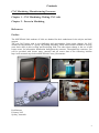
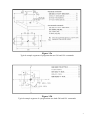
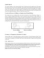
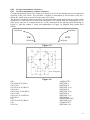
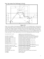
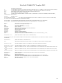
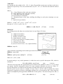
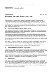
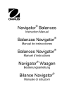
MECH3660 Manufacturing Engineering / MECH9660 Foundation in Manufacturing Engineering Compiled by Paul Briozzo School of Aerospace, Mechanical & Mechatronic Engineering University of Sydney 2015 1 Contents CNC Machining / Manufacturing Processes: Chapter 1 – CNC Machining: Writing CNC code Chapter 2 – Forces in Machining References Preface The MECH3660 5660 students of 2014 are thanked for their enthusiasm for the subject and their support. The year 2015 brings with it new challenges and opportunities. Some major changes for 2015 include the introduction of a group 3D printing laboratory which should enable students to develop some basic skills in this exciting and developing field. The other minor change is the use of pdf lecture notes for information distribution throughout the semester. Throughout the semester, you will be provided with lecture notes, tutorials and all course data at the following location http://web.aeromech.usyd.edu.au/MECH3660/Course_Documents/. Paul Briozzo February 2015 Sydney, Australia 2 Chapter 1 - CNC Machining – Writing CNC code Introduction The numerical control part of MECH3660 / MECH5660, Manufacturing Engineering, is designed to give a basic but realistic overview of the general area of CNC machine tools. In 2015, this component is roughly four weeks in duration. It incorporates a number of lectures and tutorials covering the definition and usage of CNC commands and the use of a computer package to view machining simulations. Some coverage of advanced machining methods using Solidworks / CamWorks will also be included. Aims The aim of the CNC machining part of MECH3660 / MECH5660 is to give students a basic introduction into numerically controlled machine tools such as the Mori Seiki NV4000 mill that are used in practice for producing real products. If each student gains some understanding and feel (and perhaps some enthusiasm!) for this area of manufacturing then the main aim of this component has been largely achieved. Overview The topic that students will consider in Manufacturing Engineering MECH3660 / MECH5660 for 2015 is a connecting rod. During semester there will be lectures and tutorials that will concentrate on providing you with the information and time that you will need to produce CNC code for the manufacture of the connecting rod. Some emphasis will also be placed on material removal rates and the forces generated during the machining process. Some basic coverage of rapid prototyping and the kinematics of CNC machines will also be presented as will an appreciation of the precision, accuracy and repeatability of CNC machines. 3 Programming the NV4000 mill The CNC part of this course is intended to introduce the topic of numerically controlled machines and machining, by brief descriptions of the construction and operation of such machines and comparing their function to manual processes. In addition, sample tool-path programs for simple illustrative examples are included in these notes. The software package CIMCO is available in the Undergraduate Computer rooms S345, S322 and N216. This package allows editing, graphical simulation and verification of the CNC code before it is run on the milling machine. The example programs included in these notes for the Mori Seiki NV4000 mill have every line fully described. These programs may be used as a starting point for writing and checking your own programs for your own needs. Students are encouraged to read each program included in these notes and to ensure that they understand what each function does and how it in turn influences the tool’s motion. The Mori Seiki NV4000 mill (Figure 1.0) is a standalone industrial 3-axis machine. The instructions are in a systematic CNC machine code form consisting of the so-called G & M codes. The main or more commonly used G & M codes will be covered in the lectures and will be demonstrated via examples. It is these codes that most students will use to produces their designs. Other less commonly used codes will still be included in these notes for reference purposes. Figure 1.0 Mori Seiki NV4000 mill System Specifications (Basic-Mechanical) Table size:………………………………………..700.0mm x 450.0mm Throat depth:……………………………………..139.7mm Travel (X Axis):………………………………….600.0mm Travel (Y Axis):………………………………….400.0mm Travel (Z Axis):………………………………….400.0mm Feed rates:………………………………………..1.0mm to 6000.0mm/min Accuracy:………………………………………...+/- 0.001mm Spindle speed range:……………………………..1 to 12,000 RPM Hold down provision:…………..………………..Pneumatic air vice and conventional T-Slots Motor - Spindle:…………………………………11kW (continuous) Motor - Feed:…………………………………….X:1.6kW x 2, Y:1.6kW x 2, Z:3.0kW x 2 Power requirements……………………………...27.4kVA 4 Writing a Program A part-program consists of lines of code, each comprising one block and each representing the next location of the tool centre point along the tool path. Traditionally, a line of code begins with a block number, N, followed by a G-code, indicating a geometric motion by the tool, or an M-code, representing a machine function such as turning the spindle on. The Mori Seiki mill does not require block numbers except when you need to reference back to a particular point on the program. Each line of a program has a standard form with variations according to the particular motion required for the tool and the corresponding machine codes used. Referring to Figure 1.1 and the sample code is included below; Figure 1.1 Sample code Comments N0 M03 N1 G90 N2 G00 X17.1 Y18.0 Z1.0 N3 G01 Z-5.0 F70.0 N4 G01X82.9 Y32.0 F170.0 N5 G00 Z50.0 N6 M05 N7 M02 (set spindle on) (in absolute co-ordinates) (move rapid to next position (17.1 18.0 1.0)) (move tool down (-Z) 5mm at a feed rate of 70mm/min) (move tool to position (82.9 32.0) at a feed rate of 170mm/min) (rapid feed the tool up (+Z) 50.0mm) (spindle motor off) (end of program) Feed rates, shown by an F-code, will appear in conjunction with a G01, G02 or G03 code. Most Gcodes are followed immediately by X, Y and Z values to show the next physical position of the tool centre. There is in every program an arbitrary point, called the "program zero", chosen by the partprogrammer, to which all co-ordinates are referred, whether absolute or incremental values. This point is not referred to in the program, but is implied by the co-ordinates of the tool path. The location of this zero point has to be communicated to the machine operator using a drawing of the part and of the blank as it appears before any machining is done. N.B. For ease of setting up, and checking that the program does not send the tool into the machine table, the "program zero" should always be 5 IN THE MIDDLE & AT THE TOP SURFACE OF THE BLANK If a program is already stored on a USB stick, it may be read into the memory of the controller and run. In every case, the program zero, the point from which every co-ordinate dimension is measured, is lost if the machine is shut down. For this reason, the program zero position should be set up at the start of each session. The program contained on your USB stick and the machine settings are always independent. If a co-ordinate is not specified in a line of program, as Z is not in the last example, then the previous value of Z is used. These are 'retained' or 'modal' values until they are changed by another line of program. Some G-codes behave similarly e.g. G90, G91, G01 and G02. Every command code stays effected until cancelled. Co-ordinate System The system of axes arranged in the Mori Seiki NV4000, and most milling machines of this type, is that the Z-axis is along the spindle axis (vertically upwards), the X-axis is in the largest slide direction (to the right) and the Y-axis is from the front to the back of the table. These axes are determined by the right-hand-screw direction. This means that looking from the top down onto the table, the X-axis is due east, the Y-axis is due north and the Z-axis is towards you. These directions are set so that the motion of the tool relative to the table is called positive when it moves in the positive X or Y or Z directions. Note that in actual fact it may be the table that is moving while the tool may be stationary, but the RELATIVE motion between the two is as described above. Absolute dimensions Each position for the tool is specified by giving its X, Y or Z co-ordinates with respect to a 'program zero' point. On the machine, when the program is run, the 'program zero' is set by the operator according to written instructions supplied by the programmer. When absolute co-ordinates are used the X, Y or Z values are always relative to this zero position, irrespective of where the tool is at any given time. Absolute co-ordinate mode is programmed by the G90 code. You may like to refer to Figures 1.2a and 1.2b to clarify this point. Incremental dimensions (Not recommended for beginners or students) This method of identifying the tool position means that the X, Y or Z co-ordinates are relative to the previous position of the tool. Using incremental dimensions, sometimes called chain dimensions, is very useful where the co-ordinates of a radius centre, for example, is easily determined relative to the last tangent point, but is much more difficult to find relative to the zero position. Use G91 to set the incremental co-ordinate mode. You may like to refer to Figures 1.2a and 1.2b to clarify this point. 6 Figure 1.2a Typical example segments of programs that use G90 and G91 commands Figure 1.2b Typical example segment of a program that uses both G90 and G91 commands 7 Spindle Speeds The relative hardness of the material and the type of cutting tool affect spindle speed. The harder the material is, the slower the speed should be. The load put on the spindle motor must also be taken into account. Heavy cuts at low speeds will make the motor run hotter than lighter cuts at higher speeds. The selected feed rate and the depth of cut should not cause the spindle motor to greatly lose speed or cause the tool to “chatter” against the job. The machinist usually sets the spindle speed however an approximate guide is given in a later part of these notes. Up-cut and Down-cut Milling (or Standard and Climb Milling) The cutting action of a milling cutter varies with the direction of feed. Referring to Figure 1.3 below, in up-cut milling, the direction of feed is opposite to the direction of cutter rotation. In down-cut milling, the direction of feed is the same as the direction of cutter rotation. On some manually operated mills, only up-cut milling could be performed due to the backlash or slop in its driveline. As the Mori Seiki NV4000 mill has a ball-screw driveline with no backlash in its drive, it can perform both forms of milling. However up-cut milling is still usually preferred over down-cut milling because of the likelihood of the cutting tool coming undone. Up-cut milling Down-cut milling Figure 1.3 Geometry or Preparatory Statements (G-codes) These all start with a G and relate mostly to some tool motion. The most common of these, G00, G01, G02, G03, are all self-retained and need not be repeated in consecutive blocks. Most geometry codes require co-ordinates, in Cartesian, XYZ form, in the same block to indicate the next position of the tool. G00 Rapid traverse Rapid traverse will move the tool at the maximum available feed rate: on the X and Y-axis, on the Z-axis. Rapid traverse is used to reposition the tool in preparation for the next cut, or before ending a program. Rapid traverse can be used for all tool-positioning motions to reduce run time for the part program. The G00 code remains in effect until linear (G01) or circular (G02, G03) interpolation is specified. Linear or circular interpolation will resume at the feed rate last specified prior to the rapid traverse motion unless a new feed rate is specified. Rapid traverse is never used for cutting. 8 G01 Linear interpolation Linear interpolation is the movement of the tool in a straight line from its current position to a coordinate location specified in a CNC block. Referring to Figure 1.4 and the sample G code, Sample code Comments N0 M03 (set spindle on) N1 G90 (in absolute co-ordinates) N2 G00 X7.1 Y7.1 Z1.0 (move rapid to next position (7.1 7.1 1.0)) N3 G01 Z-11.0 F70.0 (move tool down (-Z) 11mm at a feed rate of 70mm/min) N4 G01 X39.4 Y39.4 F170.0 (move tool to position (39.4 39.4) at a feed rate of 170mm/min) N5 G00 Z50.0 (rapid feed the tool up (+Z) 50mm for clearance) N6 M05 (spindle motor off) N7 M02 (end of program) Figure 1.4 9 G02 Circular interpolation (clockwise) G03 Circular interpolation (counter-clockwise) Circular interpolation moves the cutting tool along an arc from the starting point to an end-point specified in the CNC block. The curvature of motion is determined by the location of the arc’s radius (R), which must be specified in the same CNC block. The direction of rotation from the starting point determines the actual shape of the arc relative to the spindle axis. A G02 code moves the tool in a clockwise (CW) motion from the starting point; a G03 code moves the tool in counter-clockwise (CCW) motion from the starting point. Referring to Figure 1.5 plus the sample G codes and explanations in Figure 1.6 illustrate these points more clearly. Start Point StartPoint CW CCW End Point End Point Figure 1.5 Figure 1.6 G90 G01 X28.0 Y0.0 F50.0 G01 Y20.0 G03 X18.0 Y30.0 R10.0 G01 X-8.0 G02 X-28.0 Y10.0 R20.0 G01 Y-10.0 G02 X-8.0 Y-30.0 R20.0 G01 X18.0 G91 G03 X10.0 Y10.0 R10.0 G90 G01 Y0.0 (ABSOLUTE) (REGION 1) (REGION 2) (REGION 3 (a)) (REGION 4) (REGION 5 (b)) (REGION 6) (REGION 7 (c)) (REGION 8) (INCREMENTAL) (REGION 9 (d)) (ABSOLUTE) (REGION 1(e)) 10 G17 Select the XY Plane Using G17 indicates that you are intending to work in the XY plane. All work in this course is based around the XY plane. For reference, G18 refers to the XZ plane and G19 refers to the YZ plane. G28 Return the Axes to the Machine Zero Point Returns the machine to its home position in preparation for a tool change. A G91 (incremental mode) modal command must precede the G28 command. Also note that a G90 (absolute mode) modal command must be initiated before machining takes place. G40 Cancel Cutter Compensation Cutter compensation is used by professional CNC machinists as a finishing cut to a CNC project. It is usually used in conjunction with the cutter compensation commands G41 (cutter radius offset to the left) and G42 (cutter radius offset to the right). In this course we do not use G41 or G42 commands as they are tool specific commands and require more experience and understanding than we are able to provide in the time available. You may r the less please refer to the figure below for an appreciation of their use. G43 Tool Length Compensation Reference to the Suttons Tool catalogue in your notes illustrates that tool length varies with tool size and type (even short or long series within the same type). The G43 allows compensation for the tool that you have nominated in the Z axis for the tool you have nominated. This command ties in closely with H command. 11 G54 Work Coordinate System1 Select The G54 command moves the coordinate system from the machine’s coordinate system (usually located on one of the machine’s corners) to the working area. Machine Coordinate System G80 Cancel Canned Cycle Some routines such as hole drilling cycles are modal. i.e. they remain active until turned off. When completing a canned cycle or in your case for good practice, you must ensure that any canned cycles are cancelled before your program can proceed. 12 Common Control Statements These statements or codes do not involve any tool motion but set up certain parameters needed for the machining operation. Examples are described below; M00 Program Stop Program Execution and the machine stop temporarily M01 Optional Stop If the optional stop switch on the operation panel is ON: The machine stops temporarily. If the optional stop switch on the operational panel is OFF: The M01 command is ignored and the program is executed continuously. M02 End of program Takes effect after all motion has stopped; turns off motors, spindle and accessory outlets. M03 Spindle Motor On Activated concurrently with motion specified in the program block; remains in effect until superseded by another M code. M04 Spindle Motor On (Reverse) As above, only in the opposite direction. M05 Spindle Motor Off This command turns the spindle off. The command is placed as part of the header to ensure that the spindle is in the off position. This step is undertaken for safety and for completeness to ensure that the spindle is placed in a nominated position. M06 Retract and pause for tool change Generally this statement is found at the end of a sequence which uses the one tool within the program. The following sample code illustrates some of the more common control commands on lines N1, N13 and N14. The location of these commands in the program is also typical. Sample code N0 HOUSING PROGRAM N1 M03; N2; INSERT YOUR PROGRAM IN HERE N12; N13 M05; N14 M02; (10MM DIA TOOL program name & tool used (spindle on) (spindle off) (end of program) 13 M08 Coolant On M09 Coolant Off Turns the coolant on and off as required. M19 Spindle Orientation ON Turns on the feature which allows alignment of a rotating spindle in preparation for a tool change. Not always required if a M06 tool change command is used but is included for completeness. M30 End of Program and Rewind The M command M30 is similar to a M02 Program End. However G30 allows easier repetition of the same program by pressing one button on the control panel. H Command The H command calls up a predetermined height offset for the particular tool that you have nominated. In our configuration if you are using T1 then you should specify H1 as your height offset. The H commands have been numbered to correlate with the tool numbers. The H values for our pump project have been entered into the Mori Seiki controller memory by the operator beforehand. T Commands Although the T command is not part of the header they are a requirement of any program. The T command rotates the tool carousel into the required position in anticipation of a tool change. Please note that the command does not perform the tool change. The following tools available to you and their relevant T number are listed below for your reference. T1 - 3mm Long Series Slot Drill T2 - 5mm Long Series Slot Drill T3 - 5.1mm Long Series Drill T4 - 10mm Long Series Slot Drill Use the appropriate T number for your program. S Command The S command specifies the spindle speed. The Mori Seiki MV4000 is capable of spindle speeds ranging from 0-12,000 RPM. In the sample program given, a nominal value of 12,000 RPM has been specified. In your code it would be advisable if you could use the same value. If the required value differs from what you have specified. The operator will adjust the spindle speed either by editing your code or manually controlling the spindle speed override knob on the control panel. 14 Example of a profile-cut program The drawing below (Figure 1.7) describes a profile that is to be machined. Note the following points; The profile is to be manufactured from 10mm thick Perspex stock. The cutting tool available will be a 10mm slot drill (slot drill tools have the ability to cut both down and across their blades). To simplify this first example, the method of holding the job down is not considered. Note that program zero (the origin of the co-ordinate system) is located at the centre top of the object. This point can be referred to as (0,0,0) Figure 1.7 Figure 1.8 The example in Figure 1.7 shows the X and Y plane on top of the object. Figure 1.8 shows the orientation of the positive and negative axis relative to (0,0,0). The Z-axis is positive out of the page. This axis convention is referred to as the right-hand rule. The tool’s movement in the Z-axis will be mainly to lift and clear the tool as it moves to the next cutting region. 15 Basic Operations Plan Consideration must now be given to what steps must be performed in order to machine this part. This part of the exercise is called the operations plan. The operations plan describes in step-by-step text format, all the procedures involved in machining a stock piece of material to a finished product. Careful examination of the drawing (Figure 1.7) shows that the part is comprised of five holes and the profile outline. The following basic systematic operation plan is suggested for you to consider with comments to explain the reasoning behind each step. Consider machining the holes before machining the outside profile. From a common sense point of view, if the holes were not machined first, the part would fly off after the profile operation is over! With this thought in mind, the following steps are suggested. 1. 2. 3. 4. Clamp the job in position on the machine bed and load the 10mm slot drill into the chuck. The tool home position is set at 10mm above the job to enable plenty of clearance for safety. Turn the spindle motor on. The tool will move at rapid traverse to the first hole co-ordinates (select the hole closest to the home position and then plunge down at a plunge feed rate to a depth of 10mm below the top of the job. 5. Retract the tool up to Z+ 1mm so that the bottom of the tool is 1mm clear of the job. 6. At rapid traverse, move to the next hole location. 7. Moving in a counter-clockwise or clockwise manner repeat the operation for each hole. 8. After finishing the machining of the five holes, select a point on the outline and rapid traverse to that location. This position on the outline must be offset to compensate for the tool radius (5mm). 9. Plunge down at a plunge feed rate to a depth of Z-10mm. 10. Move the tool at a cutting feed rate around the profile offset 5mm to compensate for the tool diameter. 11. After finishing the machining of the profile, retract the tool up 1mm above the job and rapid traverse back to the home position. 12. Turn the spindle motor off. 13. End of program. 16 Basic Operations Plan-Machining the Holes Figure 1.9 Figure 1.9 is a subset of the drawing included in Figure 1.7. Figure 1.9 has been redimensioned with all of the dimensions, which describe the positions of the holes based from program zero, (0,0,0). This figure has been included to give a clearer picture of where all of the holes are located relative to the home position in the XY plane and the path that the cutting tool will take. The lines of code listed below represent the CNC code instructions as per the comments described in points 1 through to 7 of the Operation Plan on the previous page. N1 M03 N2 G90 N3 G00 X92.5 Y-5.0 Z1.0 N4 G01 Z-10.0 F70.0; N5 G00 Z1.0; N6 G00 X27.5 Y45.0; N7 G01 Z-10.0 F70.0; N8 G00 Z1.0; N9 G00 X-18.0 Y45.0; N10 G01 Z-10.0 F70.0; N11 G00 Z1.0; N12 G00 X-88.5 Y-45.0; N13 G01 Z-10.0 F70.0; N14 G00 Z1.0; N15 G00 X92.5 Y-45.0; N16 G01 Z-10.0 F70.0; N17 G00 Z1.0; (spindle on) (in absolute co-ordinates) (rapid traverse to hole 1-stopping 1mm above the job) (feed tool down (-Z) 11mm at a feed rate of 70mm/min) (rapid traverse up (+Z) 1mm) (rapid traverse to the location of hole 2) (feed tool down (-Z) 11mm at a feed rate of 70mm/min) (rapid traverse up (+Z) 1mm) (rapid traverse to location of hole 3) (feed tool down (-Z) 11mm at a feed rate of 70mm/min) (rapid traverse up (+Z) 1mm) (rapid traverse to the location of hole 4) (feed tool down (-Z) 11mm at a feed rate of 70mm/min) (rapid traverse up (+Z) 1mm) (rapid traverse to the location of hole 5) (feed tool down (-Z) 11mm at a feed rate of 70mm/min) (move tool up (+Z) 1mm at rapid traverse) 17 Basic Operations Plan-Machining the Profile Figure 1.10 Figure 1.10 is a subset of the drawing included in Figure 1.7. It is included to give a clearer picture of the outside profile relative to the home position in the XY plane and the path that the cutting tool will take. The cutting tool begins cutting the profile at the bottom left hand corner nearest to hole 5. This location is chosen because it is closest to where the tool finished drilling all of the holes. Hence the tool has less distance (and consequently time) to travel to its next cutting position. The lines of code listed below represent the CNC code instructions as per the comments described in points 8 through to 13 of the Operation Plan. The code is a continuation from the previous page. N18 G00 X112.5 Y-65.0 N19 G01 Z-10.0 F70.0 N20 G01 Y-5.0 F170.0 N21 G03 X92.5 Y15.0 R20.0 N22 G01 X57.5 N23 G02 X47.5 Y25.0 R20.0 N24 G01 Y45.0 N25 G03 X27.5 Y65.0 R20.0 N26 G01 X-18.0 N27 G03 X-33.77 Y57.33 R20.0 N28 G01 X-108.25 Y-37.85 N29 G03 X-112.5 Y-50.17 R20.0 N30 G01 Y-65.0 N31 G01 X112.5 N32 G00 Z1.0 N33 G00 X0.0 Y0.0 Z25.0 N34 M05 N35 M02 (rapid traverse to bottom left corner) (offsetting 5mm for the 10mm tool diameter) (feed tool down (-Z) 11mm at a feed rate of 70mm/min) (feed tool towards radius at a feed rate of 170mm/min) (feed tool c’clockwise with a 20mm radius turn) (feed tool towards next position) (feed tool clockwise with a 20mm radius turn) (feed tool towards next position) (feed tool c’clockwise with a 20mm radius turn) (feed tool towards next position) (feed tool c’clockwise with a 20mm radius turn) (the end point of the radius could be found by using trig) (feed tool towards next position) (feed tool c’clockwise with a 20mm radius turn) (feed tool towards next position) (feed tool towards next position) (rapid traverse up (+Z) 11mm) (move tool to (0.0,0.0,25.0) to allow tool removal) (spindle motor off) (end of program) 18 Mori Seiki NV4000 CNC Template 2015 (LEAVE THIS LINE BLANK) % (ALL PROGRAMS WRITTEN FOR THE MORI SEIKI NV4000 REQUIRE A "%" SYMBOL ON THE SECOND LINE OF THE FILE) O???? (ALL PROGRAMS BEGIN WITH THE CAPITAL LETTER "O" AND THE LAST FOUR DIGITS OF YOUR SID) N110 (MORI SEIKI NV4000 FORMAT TEMPLATE FOR MECH3660 MECH9660 2015) N120 (INCLUDE BELOW THIS LINE AS A HEADER) N130 (CONNECTING ROD DESIGNED BY STUDENT NAME=?, STUDENT SID=?, PART CNC CODED BY; STUDENT NAME=?, STUDENT SID=?, PART NAME=?) N140 G21 (METRIC UNITS) N150 G90G80G40G17G94G00 (G90=ABSOLUTE PROGRAMMING, G80=CANCEL CANNED CYCLE, G40=CANCEL CUTTER COMP, G17=XY PLANE, G94=FEED PER MINUTE, G00=RAPID TRAVERSE) N160 G91G28Z0 (G91=INCREMENTAL PROGRAMMING, G28=RETURN TO MACHINE HOME ON "Z" AXIS FIRST) N170 G91G28Y0 (INCREMENTAL PROGRAMMING, RETURN TO MACHINE HOME ON "Y" AXIS SECOND) N180 T? N190 N200 N210 N220 M06 N230 M01 N240 S12000 N250 M03 N260 M08 N270 G90 N280 G54 N290 (Select either T1=3mm Dia. Long Series Slot Drill) (or T2=5mm Dia. Long Series Slot Drill) (or T3=5.1mm Dia. Drill) (or T4=10mm Dia. Long Series Slot Drill) (TOOL CHANGE) (OPTIONAL STOP FOR INSPECTION/MEASUREMENT) (SPINDLE SPEED 12000 RPM) (SPINDLE MOTOR ON CW) (COOLANT ON) (ABSOLUTE PROGRAMMING) (WORK COORDINATE SYSTEM 1 SELECTED) (ENSURE ALL MACHINE COORDINATE VALUES HAVE A DECIMAL POINT eg. X2.32) N300 G00 X?.?? Y?.?? (RAPID TRAVERSE TO FIRST X AND Y COORDINATES) N310 G43 Z50.0 H? (G43=TOOL LENGTH COMPENSATION POSITIVE H?=HEIGHT OFFSET # ON SAME LINE AS FIRST "Z" RAPID MOVEMENT) N320 G00 Z15.0 (RAPID TRAVERSE TO 15MM ABOVE Z0) N330 (MACHINING OPERATIONS-INSERT YOUR CNC MACHINING CODE IN HERE AND RENUMBER) N340 G01 Z-?.? F70 (LINEAR INTERPOLATION TO Z COORDINATE AT PLUNGE FEEDRATE 70mm/MIN) N350 G01 X?.? Y?.? F170 (LINEAR INTERPOLATION TO X AND Y COORDINATES AT FEEDRATE 170mm/MIN) N360 G01 Z-12.3 F70.0 OR N370 G01 Z-10.3 F70.0 OR N380 G01 Z-20.3 F70.0 (REMOVE COMMENT:PLUNGE DISTANCE & FEEDRATE mm/min FOR PENERATION THROUGH CIRCULAR JOB) N390 G00 Z50.0 N400 M09 N410 M05 N420 G91G28Z0 N430 G91G28Y0 N440 N450 M30 (RAPID TRAVERSE TO 50.00mm ABOVE Z0.0 MOVES TOOL AWAY FROM JOB) (COOLANT OFF) (SPINDLE MOTOR OFF) (INCREMENTAL PROGRAMMING, RETURN TO MACHINE HOME ON "Z" AXIS FIRST) (INCREMENTAL PROGRAMMING, RETURN TO MACHINE HOME ON "Y" AXIS SECOND) (RETURN TO MACHINE HOME ON "X" AXIS NOT REQUIRED) (END OF PROGRAM) (REMOVE COMMENT:PLUNGE DISTANCE & FEEDRATE mm/min FOR PENERATION THROUGH 10mm LID JOB) (REMOVE COMMENT PLUNGE DISTANCE & FEEDRATE mm/min FOR PENERATION THROUGH 20mm BASE JOB) 19 Suggested Tool Types and Sizes The following pages include some of the more common commercially available tool types and sizes that are available commercially available. 20 21 22 23 24 Suggested Spindle Speeds 25 Chapter 2 - FORCE AND POWER IN MACHINING Referenced from “Materials and Process in Manufacturing” Section 21.5 pg 607– 610 8th Ed. and “Computer-Aided Manufacturing” section 6.0 basic machining calculations pg 195- 209 3rd Ed.). These two texts have been written for U.S. based Engineering students hence the use of imperial measurements. Some conversions are given below. However you may wish to either research your own conversions or use a WEB based converter such as, http://www.convertme.com/en/ A basic nomenclature of some of the terms used in this part of the notes is provided below. However, it is recommended that you read one of the two texts in order to gain a better understanding of the concepts involved. Nomenclature and some basic conversion factors applicable to Lathes CF= Correction Factor (used to account for dull tools and other issues usually set to 1.25) CT = Cutting time (sec) E = Efficiency of machine (dimensionless) HP = Horsepower (hp) MRR = Metal Removal Rate = (volume of cut) / (cutting time) V = Cutting Speed (feet per minute) Vf = Feed rate (inches per minute) f = Feed (inches per revolution) n = Number of teeth in the cutter N = Rotational speed of the cutter [drilling & milling] or work piece [turning] (revs per minute) D = Drill diameter (inches) 1 inch = 25.4mm 1 cubic inch = 16.39 cubic centimetres 1 pound force = 4.46 newtons 1 foot per minute = 0.3048 metres per minute 1 foot pound per minute = 0.0226 watts 1 horsepower = 745.7 watts The cutting force system in a conventional, oblique chip formation process is shown schematically in Figure 2.0. Oblique cutting has three components: 1. Fc: primary cutting force acting in the direction of the cutting velocity vector. This force is generally the largest force and accounts for 99% of the power requirement by the process. 2. Ff: feed force acting in the direction of the tool feed. This force is usually about 50% of Fc but accounts for only a small percentage of the power required because feed rates are usually small compared to cutting speeds. 3. Fr: radial or thrust force acting perpendicular to the machined surface. This force is typically about 50% of Ff and contributes very little to power requirements because velocity in the radial direction is negligible. Figure 2.0 shows the oblique geometry and Figure 4.1 also shows the general relationship between these forces and speed, feed and depth of cut. These figures cannot be used to determine forces for a specific process, as the following discussion will explain. The power required for cutting is: P = Fc V (ft-lb/min) (2.0-1.0) The horsepower at the spindle of the machine is therefore HP = (Fc V) / (33,000) (hp) (2.0-2.0) 26 Figure 2.0 Three measurable components of forces acting on a single-point tool (oblique machining) with effects on the forces of varying speed, depth of cut and feed. Figure 2.1 Basics of the turning process. In turning for example, where; MRR = 12 V fr d HPs = Fc / (396,000 fr d) (in3/min) (hp) (2.0-3.0) (2.0-4.0) 27 Cutting Speed The cutting speed V can be defined as the maximum linear speed between the tool and the workpiece. The cutting speed for drilling, turning and milling can be determined as a function of the workpiece or the tool diameter D and the rotation speed N and is given by V = π D N / 12 (2.0-4.1) Metal Removal Rate Metal removal rate (MRR) is a measurement of how fast material is removed from a work piece. The unit of the metal removal rate is usually expressed in cubic inches per minute. A different formula is used for different processes. In our case we will generally consider the milling formula. All three terms are included for completeness. DRILLING In drilling the cross sectional area of the chip is (π D2) / 4. Where; D = Drill Diameter, (inches) Vf = Feed Rate, (inches per min) f = Feed, (inches per revolution) N = Rotational Speed (revolutions per minute) Hence; MRRDrill = ((π D2) / 4) Vf = ((π D2) / 4) f N Because N = (12 V) / (π D) MRRDrill = ((π D2) / 4) f ((12 V) / (π D)) MRRDrill = 3 D f V (in3/min) (2.0-5.0) 28 TURNING For turning the chip width is (Do – Di) / 2, where Do and Di are the outer and inner work piece diameters, respectively. The cross-sectional area is π (D2o – D2i) / 4. Therefore the material removal rate is; Where; Do = Outer Diameter of the work piece (inches) Di = Inner Diameter of the work piece (inches) Vf = Feed Rate (inches per minute) f = Feed (inches per revolution) N = Rotational speed of the cutter [drilling & milling] or work piece [turning] (revs per minute) V = Speed (feet per minute) MRRTurn = (π (Do2 - Di2) / 4 ) Vf = (π (Do2 - Di2) / 4 ) f N Because N = (12 V) / (π (Do - Di) / 2) MRRTurn = 6 (Do - Di) f V (in3/min) (2.0-6.0) MILLING In a milling process the chip cross-sectional area is as per Figure 2.2 below. Where; ap = depth of cut (inches) w = width of cut (inches) n = number of teeth in cutter D = cutter diameter, (inches) f = feed, in. per tooth per revolution (inches) V = speed, (feet per min) Vf = feed rate (in. per min) A (cross sect. area of cut) = apw, (squared inches) MRRMill = ap w Vf Also used when considering feed in inches per tooth of revolution, MRRMill = ap w f n N Figure 2.2 Face Milling or MRRMill = ((12 ap w n) / (π D)) f V (in3/min) (2.0-7.0) Where N = (12V) / (π D) In metal cutting a very useful parameter is called the unit or specific horsepower HPs, which is defined as: HPs=(HP)/(MRR) (hp/in3/min) (hp) (2.0-8.0) Thus this term represents the approximate power needed at the spindle to remove a 1 in3 of metal per minute. Specific horsepower factors for some common materials are given in Table 2.3. Specific horsepower is related to and correlates well with shear stress for a given metal. Specific power can be used in a number of ways. First, it can be used to estimate the motor horsepower required to perform a machining operation for a given material. HPs values from the table are multiplied by the approximate MRR value for the process. The motor horsepower, HPm, is then HPm = (HPs MRR CF) / E (hp) (2.0-9.0) 29 Values for Specific or Unit HPs for Various Metals during Metal removal Material Hardness (BHN or R) Steels, including plain 85-200 carbon, alloy steel, tool, 35-40Rc hot or cold rolled, or cast 40-50Rc 50-55Rc 55-58Rc Cast iron 100-190 190-300 Stainless steels 150-450 Iron-based alloys 180-320 Nickel alloys 80-360 Nickel-cobalt based 200-360 alloys Aluminium 2014-T6, 2017-T4 30-150 at 6064-T6 150kg Pure 108 55 Hard (rolled) Hard Magnesium alloys 40-90 at 500 kg Copper 50RB Copper alloys 10-80RB 80-100RB Titanium 250-375 Tungsten, tantalum 210-320 HPs hp/in3/min 1.1 1.4 1.5 2.0 3.4 0.7-1.0 1.4-1.6 1.2-1.4 1.2-1.6 1.8-2.0 2.0-2.5 HPs Kw/cm3/min 0.050 0.064 0.068 0.091 0.155 0.03-0.045 0.05-0.07 0.05-0.068 0.055-0.073 0.082-0.091 0.09-0.11 0.250.34 0.16 0.33 0.16 0.0140.016 0.007 0.015 0.007 0.9-1.0 0.5-0.6 0.8-1.0 1.8-2.0 2.6-2.8 0.041-0.046 0.022-0.030 0.036-0.046 0.082-0.091 0.12-0.13 Comments Values assume normal feed ranges and sharp tools. Multiply value by 1.25 for a dull tool. Add 10% for milling to table value High-temperature alloys High-temperature materials Table 2.3 Where E is the efficiency of the machine. This factor accounts for the power needed to overcome friction and inertia in the machine and drive moving parts. Usually, 80% is used. Correction factors (CFs) may also be used to account for variations in cutting speed, feed and rake angle. There is usually a tool wear correction factor of 1.25 used to account for the fact that dull tools use more power than sharp tools. The primary cutting force Fc can be roughly estimated according to Fc = (HPs MRR 33000) / V (lb) (2.0-10.0) This type of estimate of the major force Fc is useful in analysis of deflection and vibration problems in machining and in the proper design of work holding devices, as these devices must be able to resist movement and deflection of the part during the process. In general, increasing the speed, feed, or depth of cut will increases the power requirement. Doubling the speed doubles the HP directly. Doubling the feed or the depth of cut doubles the cutting force Fc. In general, increasing the speed does not increase the cutting force Fc, which has also been a puzzle. Equation (2.0-7.0) can be used to estimate the maximum depth of cut, d, for a process as limited by the available power: dmax = (HPm E) / (12 HPs V fr CF) (inches) (2.0-11.0) 30 References Writing CNC code NV Series User’s Manual, Mori Seiki Editing and Simulating Machining Blackwoods Publication, Sutton Tools 1997, 13 Cooper St Smithfield, Sydney Force and Power in Machining Materials and Processes in Manufacturing, Eight Edition 1999, E. Paul DeGarmo, J T. Black and Ronald A. Kohser, Chapter 21, Section 21.5 Energy and Power in Machining, Pages 607 – 610, ISBN 0-471-36679-X Computer-Aided Manufacturing, Third Edition 2005, Tien-Chien Chang, Richard A. Wysk, Hsu-Pin Wang. Pages 195-204, Pearson Prentice Hall, ISBN 0-13-129334-6 Manufacturing Processes Manufacturing Engineering and Technology, Sixth Edition 2010, Serope Kalpakjian, Steven R. Schmid, ISBN 978-0-13-608168-5 Guidance Note 6 “Post Weld Heat Treatment of Welded Structures” Welding Technology Institute of Australia (WTIA), February 2003 31