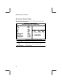
1
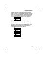
Mainboard User’s Manual This publication, including photographs, illustrations and software, is under the protection of international copyright laws, with all rights reserved. Neither this manual, nor any of the material contained herein, may be reproduced without the express written consent of the manufacturer. The information in this document is subject to change without notice. The manufacturer makes no representations or warranties with respect to the contents hereof and specifically disclaims any implied warranties of mercha ntability or fitness for any particular purpose. Further, the manufacturer reserves the right to revise this publication and to make changes from time to time in the content hereof without obligation of the manufacturer to notify any person of such revision or changes. Trademarks IBM, VGA, and PS/2 are registered trademarks of International Business Machines. Intel, Pentium, Pentium-II, Pentium-III, Pentium 4, MMX, Celeron and Tualatin are registered trademarks of Intel Corporation. Microsoft, MS-DOS and Windows 98/ME/NT/2000/XP are registered trademarks of Microsoft Corporation. PC-cillin is a trademark of Trend Micro Inc. AMI is a trademark of American Megatrends Inc. MediaRing Talk is a registered trademark of MediaRing Inc. 3Deep is a registered trade mark of E -Color Inc. It has been acknowledged that all mentioned brands or product names are trademarks or registered trademarks of their respective holders. Copyright © 2002 All Rights Reserved MS9138E Series, V3.1A VT8751/November 2002 Mainboard User’s Manual Notice: 1. Owing to Microsoft’s certifying schedule is various to every supplier, we might have some drivers not certified yet by Microsoft. Therefore, it might happen under Windows XP that a dialogue box (shown as below) pop out warning you this software has not passed Windows Logo testing to verify its compatibility with Windows XP. Please rest assured that our RD department has already tested and verified these drivers. Just click the “Continue Anyway” button and go ahead the installation. 2. USB 2.0 Driver Limitations: 2-1 The USB 2.0 driver only supports Windows XP and Windows 2000. 2-2 If you connect a USB 2.0 hub to the root hub, plugging USB devices into this hub, the system might not successfully execute certain USB devices’ connection because it could not recognize these devices. II Mainboard User’s Manual Table of Contents Chapter 1: Introduction .............................................................. 1 Key Features...................................................................... 2 Package Contents ...............................................................6 Static Electricity Precautions ...............................................7 Pre-Installation Inspection...................................................7 Chapter 2: Mainboard Installation ...............................................9 Mainboard Components....................................................10 I/O Ports..........................................................................11 Installing the Processor.....................................................12 Installing Memory Modules .............................................. 13 Jumper Settings ................................................................ 15 The Panel Connectors....................................................... 17 Other Devices Installation .................................................19 Expansion Slots Installation .............................................. 20 Connecting Optional Devices ...........................................21 Chapter 3: BIOS Setup Utility ..................................................25 Introduction .....................................................................25 Running the Setup Utility...........… … … … … … … … … … ...26 Standard CMOS Setup Page.............................................. 27 Advanced Setup Page ....................................................... 28 Power Management Setup Page .........................................31 PCI/Plug and Play Setup Page...........................................33 Load Optimal Settings ...................................................... 34 Load Best Performance Settings ........................................ 34 Features Setup Page ..........................................................35 CPU PnP Setup Page ........................................................ 37 Hardware Monitor Page....................................................38 Change Password.............................................................39 Exit .................................................................................39 Chapter 4: About the Software CD-ROM..................................41 Utility Software Reference................................................ 42 III 1: Introduction Chapter 1 Introduction This mainboard has a Socket 478 for the Intel Pentium 4 type of processors supporting front side bus (FSB) speeds up to 400 MHz. This mainboard has the VIA VT8751(P4M266) Northbridge and VT8235 Southbridge chipsets that support AC 97 audio codec, and provide Ultra DMA 66/100/133 function. It supports built-in USB 2.0 providing higher bandwidth. It implements Universal Serial Bus Specification Revision 2.0 and is compliant with UHCI 1.1 and EHCI 0.95. This mainboard has two 32-bit PCI slots, one 4xAGP slot, one CNR (Communications and Networking Riser) slot, and an onboard 10BaseT/100BaseTX Network interface. In addition, this mainboard has a full set of I/O ports including two PS/2 ports for mouse and keyboard, one serial port, one VGA port, one parallel port, one MIDI/game port and maximum six USB ports (USB 2.0) --two back-panel ports and onboard USB headers make four extra USB ports by connecting the Extended USB Module to the mainboard. This mainboard is a Micro ATX size mainboard and has power connectors for an ATX power supply. 1 Mainboard User’s Manual Key Features This mainboard has these key features: Socket 478 Processor ♦ The PGA Socket 478 ♦ Accommodates Intel Pentium 4 CPUs ♦ Supports a front-side bus (FSB) of 400 MHz Chipset There are VT8751(P4M266) Northbridge and VT8235 Southbridge in this chipset in accordance with an innovative and scalable architecture with proven reliability and performance. A few of the chipset’s advanced features are: ♦ An advanced V -Link memory controller architecture that provides the bandwidth up to 266 MB/s and performance necessary for even the most demanding Internet and 3D graphics ♦ Support for an 4xAGP interface providing vivid 3D graphics and video performance ♦ An ATA 133 interface on the chipset, which helps boost system performance by providing a high-speed connection to ATA 133 Hard Disk Drives, delivering maximum sustained data transfer rates of 133 MB/sec Additional key features include support for six USB ports, an AC 97 link for audio and modem, hardware monitoring, and ACPI/OnNow power management. Memory Support ♦ The mainboard accommodates 2 DDR + 2 SDR 168 pin, 3.3V DIMM sockets with a total capacity of 2 GB system memory. 2 1: Introduction Built-in Graphics System ♦ P4M266 integrates S3’s Savag8 graphics accelerator into a single chip. P4M266 brings mainstream graphics performance to the Value PC with leading-edge 2D, 3D and DVD video acceleration into a cost effective package. Based on its capabilities, P4M266 is an ideal solution for the consumer, corporate mobile users and entry level professionals. ♦ Maximum shared memory size is 32 MB. VGA ♦ This mainboard includes a 4xAGP slot that provides four times the bandwidth of the original AGP specification. AGP technology provides a direct connection between the graphics sub-system and memory so that the graphics do not have to compete for processor time with other devices on the PCI bus. AC’97 Audio Codec ♦ Compliant with AC’97 2.1 specification ♦ 16-bit stereo full-duplex CODEC with fixed 48KHz sampling rate ♦ 3 analog line-level stereo inputs with 5-bit volume control: LINE-IN, CD-IN, AUX-IN ♦ 1 analog line-level mono input: PHONE-IN ♦ Three Audio Jacks – Line-Out, Line-In and Microphone-In ♦ Sound Blaster, Sound Blaster Pro Compatible ♦ Digital I/O compatible with consumer mode S/PDIF ♦ Advanced power management support 3 Mainboard User’s Manual Expansion Options The mainboard comes with the following expansion options: ♦ Two 32-bit PCI slots capable of Ultra DMA bus mastering with transfer rates of 66/100/133 MB/sec ♦ An 4xAGP slot ♦ A CNR (Communications and Networking Riser) slot Onboard I/O Ports The mainboard has a full set of I/O ports and connectors: ♦ Two PS/2 ports for mouse and keyboard ♦ One serial port ♦ One VGA port ♦ One parallel port ♦ One MIDI/game port ♦ Six USB ports (two back-panel ports, onboard USB headers providing four extra ports: header USB1 and USB2) — all support USB 2.0 ♦ Audio jacks for microphone, line-in and line-out BIOS Firmware This mainboard uses AMI BIOS that enables users to configure many system features including the following: ♦ Power management ♦ Wake-up alarms ♦ CPU parameters and memory timing ♦ CPU and memory timing The firmware can also be used to set parameters for different processor clock speeds. USB 2.0 ♦ Compliant with Universal Serial Bus Specification Revision 2.0 ♦ Compliant with Intel’s Enhanced Host Controller Interface Specification Revision 0.95 ♦ Compliant with Universal Host Controller Interface Specification Revision 1.1 4 1: Introduction ♦ PCI multi-function device consists of two UHCI Host Controller cores for full-/low-speed signaling and one EHCI Host Controllercore for high-speed signaling ♦ Root hub consists 4 downstream facing ports with integrated physical layer transceivers shared by UHCI and EHCI Host Controller ♦ Support PCI-Bus Power Management Interface Specification release 1.1 ♦ Legacy support for all downstream facing ports Built-in Ethernet LAN ♦ Built-in 10BaseT/100BaseTX Ethernet LAN ♦ VT8235 integrates Fast Ethernet MAC and VT6103 LAN PHY in compliance with IEEE802.3u 100BASE-TX, 10BASE-T and ANSI X3.263 TP-PMD standards ♦ In compliance with ACPI 1.0 and the Network Device Class Power Management 1.0 ♦ High Performance achieved by 100Mbps clock generator and data recovery circuit for 100Mbps receiver Bundled Software ♦ PC-Cillin 2000 provides automatic virus protection under Windows 98/ME/NT/2000/XP ♦ MediaRing Talk provides PC to PC or PC to Phone internet phone communication ♦ 3Deep delivers the precise imagery and displays accurate color in your monitor st ♦ Recovery Genius 21 V5.0 provides the function to recover, reserve and transfer hard disk data . ♦ CD Ghost is the software stimulating a real CD-ROM to perform equivalent function. st ♦ Language Genius 21 is the software to provides learning tools of language and singing. ♦ PC DJ is a dual-MP3 player that enables users to actually mix music right on their own personal computers. ♦ Adobe Acrobat Reader V5.0 is the software to help users read .PDF files. 5 Mainboard User’s Manual Dimensions ♦ Micro ATX form factor of 244 x 244 mm Package Contents Your mainboard package contains the following items: q The mainboard q The User’s Manual q One diskette drive ribbon cable q One IDE drive ribbon cable q Software support CD Optional Accessories You can purchase the following optional accessories for this mainboard. q Extended USB module q CNR v.90 56K Fax/Modem card 6 1: Introduction Static Electricity Precautions Static electricity could damage components on this mainboard. Take the following precautions while unpacking this mainboard and installing it in a system. 1. Don’t take this mainboard and components out of their original static-proof package until you are ready to install them. 2. While installing, please wear a grounded wrist strap if possible. If you don’t have a wrist strap, discharge static electricity by touching the bare metal of the system chassis. 3. Carefully hold this mainboard by its edges. Do not touch those components unless it is absolutely necessary. Put this mainboard on the top of static-protection package with component side facing up while installing. Pre-Installation Inspection 1. Inspect this mainboard whether there are any damages to components and connectors on the board. 2. If you suspect this mainboard has been damaged, do not connect power to the system. Contact your mainboard vendor about those damages. 7 Mainboard User’s Manual 8 2: Mainboard Installation Chapter 2 Mainboard Installation To install this mainboard in a system, please follow these instructions in this chapter: q q q q q q q Identify the mainboard components Install a CPU Install one or more system memory modules Make sure all jumpers and switches are set correctly Install this mainboard in a system chassis (case) Connect any extension brackets or cables to connecting headers on the mainboard Install other devices and make the appropriate connections to the mainboard connecting headers. Note: 1. Before installing this mainboard, make sure jumper JBAT1 is under Normal setting. See this chapter for information about locating JBAT1 and the setting options. 2. Never connect power to the system during installation; otherwise, it may damage the mainboard. 9 Mainboard User’s Manual Mainboard Components Identify major components on the mainboard via this diagram underneath. Note: Those jumpers of mainboard not appearing in this illustration are for testing only. 10 2: Mainboard Installation I/O Ports The illustration below shows a side view of the built-in I/O ports on the mainboard. PS/2 mouse PS/2 keyboard LAN port USB ports Parallel port (LPT1) Serial port COM 1 VGA Game port Microphone Line-in Line-out 1. 2. 3. 4. 5. 6. 7. 8. Upper PS/2 port connects a PS/2 pointing device. Lower PS/2 port connects a PS/2 keyboard. USB ports connect USB devices. LPT1 connects printers or other parallel communications devices. COM1 port connects serial devices such as mice or fax/modems; the VGA port to connect graphic display devices. Game port connects a joystick or a MIDI device. Three audio ports connect audio devices. The left side jack is for a stereo line-out signal. The middle jack is for a stereo line-in signal. The right side jack is for a microphone. LAN port connects the network. 11 Mainboard User’s Manual Installing the Processor This mainboard has a Socket 478 processor socket. When choosing a processor, consider the performance requirements of the system. Performance is based on the processor design, the clock speed and system bus frequency of the processor, and the quantity of internal cache memory and external cache me mory. CPU Installation Procedure Follow these instructions to install the CPU: 1. Unhook the CPU socket’s locking lever by pulling it away from socket and raising it to the upright position. 2. Match the pin 1 corner of CPU socket to the one of processor, and insert the processor into the socket. Do not use force. 3. Push the locking lever down and hook it under the latch on the edge of socket. 4. Apply thermal grease to the top of the CPU. 5. Lower the CPU fan/heatsink unit onto the CPU and CPU socket, and then use the retention module clamps to snap the fan/heatsink into place. 6. Plug the CPU fan power cable into the CPU cooling fan power supply (CPU_FAN) on the mainboard. 12 2: Mainboard Installation Installing Memory Modules This mainboard accommodates 168-pin 3.3V/184-pin 2.5V unbuffered SDRAM memory modules. The memory chips must be standard or registered SDRAM (Synchronous Dynamic Random Access Memory). The CPU supports 100MHz system bus. The SDRAM DIMMs and DDRs can synchronously work with 100 MHz or operates over a 266 MHz system bus. You must install at least one memory module in order to work out this mainboard, either SDRAM or DDR SDRAM, but you can’t use them simultaneously. SDRAM provides 800 MB/s or 1 GB/s data transfer rate corresponding with the bus 100 MHz or 266 MHz. It doubles the rate to 1.0 GB/s and 2.1 GB/s by transferring data on both the rising and falling edges of the clock. DDR SDRAM uses additional power and ground lines and requires 184-pin 2.5V unbuffered DIMM module rather than the 168-pin 3.3V unbuffered DIMMs used by SDRAM. DIMM1 DDR1 DIMM2 DDR2 13 Mainboard User’s Manual Installation Procedure The mainboard accommodates two memory modules. You must install at least one module in any of these sockets. Each module can be installed with up to 2GB system memory. Refer to the following to install the memory modules. 1. Push the latches on each side of the DIMM socket down. 2. Align the memory module with the socket. The DIMM sockets are keyed with notches and the DIMMs are keyed with cutouts so that they can only be installed correctly. 3. Check that the cutouts on the DIMM module edge connector match the notches in the DIMM socket. 4. Install the DIMM module into the socket and press it firmly down until it is seated correctly. The socket latches are levered upwards and latch on to the edges of the DIMM. 5. Install any remaining DIMM modules. 14 2: Mainboard Installation Jumper Settings 1 PANEL1 JP4 JP2 1 1 JP1A1 JP1B1 1 1 1 JP16 1 PANEL2 JBAT1 1 JP1 JBAT1: Clear CMOS Jumper This jumper is to clear the contents of CMOS memory. You may need to clear the CMOS memory if the settings in the Setup Utility are incorrect that prevents your mainboard from operating. To clear the CMOS memory, disconnect all the power cables from the mainboard and then move the jumper cap into the CLEAR setting for a few seconds. Function Normal Clear CMOS Jumper Setting Short Pins 1-2 Short Pins 2-3 JP1A1, JP1B1: CPU Clock This jumper enables to select CPU frequency. CPU Clock 100M 133M JP1A1 Short Pins 1-2 Short Pins 2-3 JP1B1 Short Pins 2-3 Short Pins 1-2 15 Mainboard User’s Manual JP1: DRAM Voltage (VCC) This jumper enables to select voltage of DRAM. Function 2.5V (DDR) 3V (SDR) Jumper Setting Open Pins 1-2 Short Pins 1-2 J2A/B/C/D, J3A/B/C/D: DDR/SDR DRAM Type Selector This jumper enables to select the type of DDR or SDR DRAM. Function DDR1,DDR2 DIMM1, DIMM2 Jumper Setting Short all J2A/B/C/D and J3A/B/C/D pins Open all J2A/B/C/D and J3A/B/C/D pins JP2: Keyboard Power On This jumper enables any keyboard activity to power up a system previously in a standby or sleep state. Function 5V 5VSB Jumper Setting Short Pins 1-2 Short Pins 2-3 J13: Flash ROM Voltage (VCC) This jumper enables to select voltage of flash ROM. Function 5V 3V Jumper Setting Short Pins 1-2 Short Pins 2-3 JP4: Flash ROM Size This jumper enables to select size of flash ROM. Function 2M 4M 16 Jumper Setting Short Pins 1-2 Short Pins 2-3 2: Mainboard Installation The Panel Connector PANEL1 If there are a headphone jack or/and a microphone jack on the front panel, connect the cables to the PANEL1 on the mainboard. Device Pins Line Out (L) 9, 10 Empty 8 NC 7 Line Out (R) 5, 6 +5V Audio 4 VCCMIC 3 +5V Audio (Pin 4) VCC MIC (Pin 3) GND 2 GND (Pin 2) MIC IN 1 MIC IN (Pin 1) 10 9 Line Out(L) (Pin 9) Line Out(L) (Pin 10) Empty (Pin 8) NC (Pin 7) Line Out(R) (Pin 6) Line Out(R) (Pin 5) 2 1 PANEL2 This panel connector provides a set of switch and LED connectors found on ATX case. Refer to the table below for information. Device Pins Empty 10 N/C 9 Power ON/OFF 6, 8 Reset Switch 5, 7 SPD-LED Indicator +2, 4 HDD LED + +1, -3+ 10 9 Empty (Pin 10) N/C (Pin 9) Reset Switch (Pins 5, 7) Power Switch (Pins 6, 8) SPD-LED (Pins 2, 4) HDD LED (Pins 1, 3) 2 1 17 Mainboard User’s Manual J16: LAN LED Indicator This connector is attached to LAN device that needs a LED indicator. Device Pins Link LED 1 1, +2 ACT LED + +3, 4 LINK LED + ACT LED 4 Note: The plus sign (+) indicates a pin which must be connected to a positive voltage. 18 2: Mainboard Installation Other Devices Installation Floppy Diskette Drive Installation The mainboard has a floppy diskette drive (FDD) interface and ships with a diskette drive ribbon cable that supports one or two floppy diskette drives. You can install a 5.25-inch drive and a 3.5inch drive with various capacities. The floppy diskette drive cable has one type of connector for a 5.25-inch drive and another type of connector for a 3.5-inch drive. IDE Devices Your mainboard has a primary and secondary IDE channel interface (IDE1 and IDE2). An IDE ribbon cable supporting two IDE devices is bundled with the mainboard. If you want to install more than two IDE devices, get a second IDE cable and you can add two more devices to the secondary IDE channel. IDE devices have jumpers or switches to set the IDE device as MASTER or SLAVE. When installing two IDE devices on one cable, ensure that one device is set to MASTER and the other one to SLAVE. This mainboard supports Ultra DMA 66/100/133. UDMA is a technology to accelerate devices’ performance in the IDE channel. To maximize performance, install IDE devices that support UDMA and use 80-pin IDE cables supporting UDMA 66/100/133. 19 Mainboard User’s Manual Expansion Slots Installation This mainboard has two 32-bit PCI (Peripheral Components Interconnect) expansion slots, one 4xAGP slot, and one CNR slot. PCI Slots PCI slots are used to install expansion cards that have the 32-bit PCI interface. 4 x AGP Slot The 4xAGP slot is used to install a graphics adapter that supports the 4xAGP specification and has a 4xAGP edge connector. CNR Slot The Communications Networking Riser (CNR) slot can be used to insert a CNR card. CNR1 Slot PCI Slot AGP Slot 1. Remove a blanking plate from the system case corresponding to the slot you are going to use. 2. Install the edge connector of the expansion card into the expansion slot. Ensure that the edge connector is correctly seated in the slot. 3. Secure the metal bracket of the card to the system case with a screw. 20 2: Mainboard Installation Connecting Optional Devices Refer to the following for information on connecting the mainboard’s optional devices: 1 1 SIR1 CD2 CD1 WOM1 WOL1 SPK1 1 J12 1 1 USB1 USB2 1 21 Mainboard User’s Manual J12: Sleep Switch This header is connected to the sleep button for suspending the computer’s activity if pushing the button. Or, the computer is automatic ally suspended after passing a period of time. Pin 1 2 Signal -EXTSMI GND SPK1: Speaker Connector Connect the cable from the PC speaker to the SPK1 header on the mainboard. Pin 1 3 Signal SPKR GND Pin 2 4 Signal NC +5V USB1/USB2(USB 2.0): Front panel USB headers The mainboard has USB ports installed on the rear edge I/O port array. Some computer cases have a special module that mounts USB ports at the front of the case. If you have this kind of case, use auxiliary USB connectors USB1 and USB2 to connect the frontmounted ports to the mainboard. Pin 1 3 5 7 9 Signal VERG_FP_USBPWR0 USB_FP_P0USB_FP_P0+ GROUND KEY Pin 2 4 6 8 10 Signal VERG_FP_USBPWR0 USB_FP_P1USB_FP_P1+ GROUND USB_FP_OC0 WOL1/WOM1: Wake On LAN/Wake On Modem If you have installed a LAN card, use the cable provided with the card to plug into the mainboard WOL1 connector. This enables the Wake On LAN (WOL1) feature. When your system is in a powersaving mode, any LAN signal automatically resumes the system. You must enable this item using the Power Management page of the Setup Utility. 22 2: Mainboard Installation If you have installed a modem, use the cable provided with the modem to plug into the mainboard WOM1 connector. This enables the Wake On Modem (WOM1) feature. When your system is in a power-saving mode, any modem signal automatically resumes the system. You must enable this item using the Power Management page of the Setup Utility. See Chapter 3 for more information. Pin 1 2 3 Signal 5VSB GND -RING CD1/2:CD-ROM/DVD Audio Input Connector If you have installed a CD-ROM drive or DVD-ROM drive, you can connect the drive audio cable to the onboard sound system. On the mainboard, locate the two 4-pin connectors CD1 and CD2. There are two kinds of connector because different brands of CD ROM drive have different kinds of audio cable connectors. Connect the cable to the appropriate connector. CD1 Pin 1 2 3 4 Signal GND CD IN L GND CD IN R CD2 Pin 1 2 3 4 Signal CD IN L GND GND CD IN R 23 Mainboard User’s Manual SIR1: Serial infrared port The mainboard supports a Serial Infrared (SIR1) data port. Infrared ports allow the wireless exchange of information between your computer and similarly equipped devices such as printers, laptops, Personal Digital Assistants (PDAs), and other computers. Pin 1 3 5 24 Signal NC +5V IRTX Pin 2 4 6 Signal KEY GND IRRX 3: BIOS Setup Utility Chapter 3 BIOS Setup Utility Introduction The BIOS Setup Utility records settings and information of your computer, such as date and time, the type of hardware installed, and various configuration settings. Your computer applies those information to initialize all the components when booting up and basic functions of coordination between system components. If the Setup Utility configuration is incorrect, it may cause the system to malfunction. It can even stop your computer booting properly. If it happens, you can use the clear CMOS jumper to clear the CMOS memory which has stored the configuration information; or you can hold down the Page Up key while rebooting your computer. Holding down the Page Up key also clears the setup information. You can run the setup utility and manually change the configuration. You might need to do this to configure some hardware installed in or connected to the mainboard, such as the CPU, system memory, disk drives, etc. 25 Mainboard User’s Manual Running the Setup Utility Every time you start your computer, a message appears on the screen before the operating system loading that prompts you to “Hit <DEL>if you want to run SETUP”. Whenever you see this message, press the Delete key, and the Main menu page of the Setup Utility appears on your monitor. AMIBIOS SIMPLE SETUP UTILITY – VERSION 1.21.12 (C) 2000 American Megatrends, Inc. All Rights Reserved Standard CMOS Setup Advanced Setup Features Setup CPU PnP Setup Power Management Setup Hardware Monitor PCI / Plug and Play Setup Change Password Load Optimal Settings Exit Load Best Performance Settings Esc : Quit ↑ ↓ ← →: Select Item (Shift)F2 : Change Color F5 : Old Values F6 : Optimal values F7 : Best performance values F10 : Save&Exit Standards COMOS setup for changing time, date, hard disk type, etc. You can use cursor arrow keys to highlight anyone of options on the main menu page. Press Enter to select the highlighted option. Press the Escape key to leave the setup utility. Hold down the Shift key and press F2 to cycle through the Setup Utility’s optional color schemes. Some options on the main menu page lead to tables of items with installed values that you can use cursor arrow keys to highlight one item, and press PgUp and PgDn keys to cycle through alternative values of that item. The other options on the main menu page lead to dialog boxes requiring your answer Yes or No by hitting the Y or N keys. If you have already changed the setup utility, press F10 to save those changes and exit the utility. Press F5 to reset the changes to the original values. Press F6 to install the setup utility with a set of default values. Press F7 to install the setup utility with a set of high-performance values. 26 3: BIOS Setup Utility Standard CMOS Setup Page This page helps you set up basic information such as the date and time, the IDE devices, and the diskette drives. AMIBIOS SETUP – STANDARD CMOS SETUP (C) 2000 American Megatrends, Inc. All Rights Reserved Date (mm/dd/yy) : Mon Nov 04, 2002 Time (hh/mm/ss) : 15:28:50 Type Pri Master : Auto Pri Slave : Auto Sec Master : Auto Sec Slave : Auto LBA Blk PIO 32Bit Size Cyln Head WPcom Sec Mode Mode Mode Mode On On On On Floppy Drive A : 1.44 MB 31/2 Floppy Drive B : Not Installed Month : Jan – Dec Day : 01 – 31 Year : 1901 – 2099 ESC : Exit ↑↓ : Select Item PU/PD/+/- : Modify (Shift)F2 : Color F3 : Detect All HDD Use these items to set up system date and time IDE Pri Master Use these items to configure devices connected to the Primary and Secondary IDE Pri Slave Sec Master channels. To configure an IDE hard disk drive, choose Auto. If the Auto setting fails to Sec Slave find a hard disk drive, set it to User, and then fill in the hard disk characteristics (Size, Cyls, etc.) manually. If you have a CD-ROM drive, select the setting CDROM. If you have an ATAPI device with removable media (e.g. a ZIP drive or an LS-120), select Floptical. Floppy Drive A Use these items to set up size and capacity of Floppy Drive B the floppy diskette drive(s) installed in the system. Date & Time 27 Mainboard User’s Manual Advanced Setup Page This page sets up more advanced information about your system. Be more careful to this page. Any changes can affect the operation of your computer. AMIBIOS SETUP – ADVANCED SETUP (C) 2000 American Megatrends, Inc. All Rights Reserved Quick Boot 1st Boot Device 2nd Boot Device 3rd Boot Device Try Other Boot Devices S.M.A.R.T. for Hard Disks BootUp Num-Lock Floppy Drive Swap Floppy Drive Seek Password Check Boot To OS/2 L2 Cache System BIOS Cacheable SDRAM Timing by SPD SDRAM Frequency SDRAM CAS# Latency SDRAM Bank Interleave AGP Mode AGP Comp. Driving Manual AGP Comp. Driving Quick Boot 1 st Boot Device 2 nd Boot Device 3 rd Boot Device Try Other Boot Device 28 Enabled IDE-0 Floppy CDROM Yes Disabled On Disabled Disabled Setup No Enabled Enabled Disables 100MHz 2.5 Disabled 4X Auto CB AGP Aperture Size Auto detect DIMM/PCI Clk CLK Gen Spread Spectrum ESC : Quit F1 : Help 64MB Enabled Disabled ↑↓←→ : Select Item PU/PD/+/ - : Modify F5 : Old Values (Shift)F2 : Color F6 : Load BIOS Defaults F7 : Load Setup Defaults If you enable this item, the system starts up more quickly be elimination some of the power on test routines. Use these items to determine the device order the computer uses to look for an operating system to load at start-up time. If you enable this item, the system will also search for other boot devices if it fails to find an operating system from the first two locations. 3: BIOS Setup Utility S.M.A.R.T. for Hard Disks BootUp NumLock Floppy Drive Swap Floppy Drive Seek Password Check Boot to OS/2 > 64MB L2 Cache System BIOS Cacheable DOS Flat Mode SDRAM Timing By SPD Enable this item if any IDE hard disks support the S.M.A.R.T. (SelfMonitoring, Analysis and Reporting Technology) feature. This item determines if the Num Lock key is active or inactive at system startup time. If you have two diskette drives installed and you enable this item, drive A becomes drive B and drive B becomes drive A. If you enable this item, your system will check all floppy disk drives at start up. Disable this item unless you are using an old 360KB drive. If you have entered a password for the system, use this item to determine, if the password is required to enter the Setup Utility (Setup) or required both at startup and to enter the Setup Utility (Always). Enable this item if you are booting the OS/2 operating system and you have more than 64MB of system memory installed. Leave these items enabled since all the processors that can be installed on this board have internal L2 cache memory. If you enable this item, a segment of the system BIOS will be copied to main memory for faster execution. This item enables BIOS to enter the DOS protected mode without other software supporting under the DOS operating system. We recommend you leave this item at the default value. This item allows you to enable or disable the SDRAM timing defined by the Serial Presence Detect electrical. 29 Mainboard User’s Manual This item determines frequency of SDRAM memory. This item determines the operation of SDRAM memory CAS (column address strobe). It is recommended that you leave this item at the default value. The 2T setting requires faster memory that specifically supports this mode. Enable this item to increase SDRAM SDRAM Bank memory speed. When enabled, separate Interleave memory banks are set for odd and even addresses and the next byte of memory can be accessed while the current byte is being refreshed. Use this item to signal driving current on AGP Comp. AGP cards to auto or manual. Some Driving AGP cards need stronger than normal driving current in order to operate. We recommend that you set this item to the default. When AGP Driving is set to Manual, use Manual AGP this item to set the AGP current driving Comp. Driving value. This item provides the OnBoard VGA AGP Mode mode with three options of 1,2, 4 multiplied frequency. This item defines an AGP for the AGP Aperture graphics. Leave this item at the default Size value 64MB. When this item is enabled, BIOS will Auto detect disable the clock signal of free DIMM/PCI DIMM/PCI slots. Clock Use this item to set the system bus CLK GEN Spread Spectrum spread spectrum for the installed processor. SDRAM Frequency SDRAM CAS# Latency 30 3: BIOS Setup Utility Power Management Setup Page This page sets up some parameters of system power management operation. AMIBIOS SETUP – POWER MANAGEMENT SETUP (C) 2000 American Megatrends, Inc. All Rights Reserved ACPI Aware O/S Power Management Suspend Time Out Hard Disk Time Out Resume On RTC Alarm RTC Alarm Date RTC Alarm Hour RTC Alarm Minute RTC Alarm Second LAN/Ring Power On Keyboard Power On Wake-Up Key Wake-Up Password ACPI Aware O/S Power Management Suspend Time Out Hard Disk Time Out Yes Enabled Disabled Standby Disabled 15 12 30 30 Disabled Disabled Any key N/A ESC : Quit ↑↓←→ : Select Item F1 : Help PU/PD/+/ - : Modify F5 : Old Values (Shift)F2 : Color F6 : Load BIOS Defaults F7 : Load Setup Defaults This item supports ACPI (Advanced Configuration and Power management Interface). Use this item to enable or disable the ACPI feature. Use this item to enable or disable a power management scheme. If you enable power management, you can use the items below to set the power management operation. Both APM and ACPI are supported. This sets the timeout for Suspend mode in minutes. If the time selected passes without any system activity, the computer will enter power-saving Suspend mode. This item sets up the timeout to power down the hard disk drive, if there is no hard disk activity after passing the preset period of time. 31 Mainboard User’s Manual The system can be turned off with a software command. If you enable this item, the system can automatically resume at a fixed time based on the system’s RTC (realtime clock). Use the items below this one to set the date and time of the wake-up alarm. You must use an ATX power supply in order to use this feature. The system can be turned off with a LAN/Ring software command. If you enable this item, Power On the system can automatically resume if there is an incoming call on the Modem. You must use an ATX power supply in order to use this feature. If you enable this item, system can Keyboard automatically resume by pressing hot keys Power On Wake-Up Key on the keyboard or typing in the password. You must enable the Keyboard Power On Wake-Up jumper and use an ATX power supply in Password order to use this feature. Resume On RTC Alarm / Date / Hour / Minute / Second 32 3: BIOS Setup Utility PCI / Plug and Play Setup Page This page sets up some parameters for devices installed on the PCI bus and those utilizing the system plug and play capability. AMIBIOS SETUP – PCI / PLUG AND PLAY SETU P (C) 2000 American Megatrends, Inc. All Rights Reserved Plug and Play Aware O/S Share Memory Size Primary Graphics Adapter Allocate IRQ for PCI VGA PCI IDE BusMaster Plug and Play Aware O/S Share Memory Size Primary Graphics Adapter Allocate IRQ for PCI VGA PCI IDE BusMaster Yes 32MB PCI Yes Disabled ESC : Quit F1 : Help ↑↓←→ : Select Item PU/PD/+/ - : Modify F5 F6 : Old Values (Shift)F2 : Color : Load BIOS Defaults F7 : Load Setup Defaults Enable this item if you are using an O/S that supports Plug and Play such as Windows 95 or 98. This item lets you allocate a portion of the main memory for the onboard VGA display application with three options of 8/16/32MB. This item indicates if the primary graphics adapter uses the PCI or the AGP bus. The default AGP setting still lets the onboard display work and allows the use of a second display card installed in an AGP slot. If this item is enabled, an IRQ will be assigned to the PCI VGA graphics system. You set this value to No to free up an IRQ. This item enables or disables the DMA under DOS mode. We recommend you to leave this item at the default value. 33 Mainboard User’s Manual Load Optimal Settings If you select this item and press Enter a dialog box appears. If you press Y, and then Enter, the Setup Utility loads a set of fail-safe default values. These default values are not very demanding and they should allow your system to function with most kinds of hardware and memory chips. Note: It is highly recommended that users enter this option to load optimal values for accessing the best performance. Load Best Performance Settings If you select this item and press Enter a dialog box appears. If you press Y, and then Enter, the Setup Utility loads a set of bestperformance default values. These default values are quite demanding and your system might not function properly if you are using slower memory chips or other low-performance components. 34 3: BIOS Setup Utility Features Setup Page This page sets up some parameters for those peripher al devices connected to the system. AMIBIOS SETUP – FEATURES SETUP (C) 2000 American Megatrends, Inc. All Rights Reserved OnBoard FDC OnBoard Serial PortA OnBoard IR Port OnBoard Parallel Port Parallel Port Mode Parallel Port IRQ Parallel Port DMA OnBoard Game Port OnBoard MIDI Port MIDI Port IRQ OnBoard IDE Audio Device Modem Device Ethernet Device USB Controller USB Device Legacy Support ThumbDrive Support for DOS Enabled 3F8h/COM1 Disabled 378h SPP 7 N/A 201h 300h 10 Both Enabled Auto Enabled Enabled Disabled Disabled ESC : Quit Item ↑↓←→ : Select F1 : Help PU/PD/+/ - : Modify F5 F6 : Old Values (Shift)F2 : Color : Load BIOS Defaults F7 : Load Setup Defaults Use this item to enable or disable the onboard floppy disk drive interface. OnBoard Serial Use this item to enable or disable the onboard COM1 serial port, and to assign a PortA port address. Use this item to enable or disable the OnBoard IR onboard infrared port, and to assign a port Port address. Use this item to set the parallel port mode. Parallel Port You can select SPP (Standard Parallel Mode Port), ECP (Extended Capabilities Port), EPP (Enhanced Parallel Port), or ECP + EPP. Use this item to assign IRQ to the parallel Parallel Port port. IRQ OnBoard FDC 35 Mainboard User’s Manual Use this item to assign a DMA channel to the parallel port. This item enables or disables the I/O address for the game port. Use this item to enable or disable the onboard MIDI port, and to assign a port address. MIDI Port IRQ Use this item to assign IRQ 7 to the parallel port. Use this item to enable or disable the OnBoard IDE onboard IDE channel. This item enables or disables the AC’97 Audio Device audio chip. Modem Device This item enables or disables the MC’97 modem chip. This item enables or disables the onboard Ethernet Ethernet LAN. Device Use this item to select the USB ports or USB disabled. Controller This item allows you to enable the USB USB Device device, if you have installed a USB device Legacy on the system board. Support Enable this item to make a small portion of ThumbDrive memory storage device for the USB ports. Support For DOS Parallel Port DMA OnBoard Game Port OnBoard MIDI Port 36 3: BIOS Setup Utility CPU PnP Setup Page This page helps you manually configure the mainboard for the CPU. The system will automatically detect the type of installed CPU and make the appropriate adjustments to the items on this page. AMIBIOS SETUP – CPU PnP SETUP ©2000 American Megatrends, Inc. All Rights Reserved CPU BRAND CPU Type CPU Ratio CPU Frequency INTEL Pentium 4 8.0x 100 MHz ESC F1 F5 F6 F7 CPU BRAND/Type/ Core Voltage/Ratio /Frequency : Quit ↑↓←→ : Select Item : Help PU/PD/+/ - : Modify : Old Values (Shift)F2 : Color : Load Optimal values : Load Best performance values These items show the type, core voltage, ratio and frequency of CPU installed in your system. 37 Mainboard User’s Manual Hardware Monitor Page This page sets up some parameters for the hardware monitoring function of this mainboard. AMIBIOS SETUP – HARDWARE MONITOR (C) 2000 American Megatrends, Inc. All Rights Reserved *** System Hardware *** Vcore Vcc 2.5V Vcc 3.3V Vcc 5V +12V -12V SB5V VBAT SYSTEM Fan Speed CPU Fan Speed Power Temperature SYSTEM Temperature CPU Temperature CPU / System Temperature FANs & Voltage Measurements 38 1.632V 2.496V 3.392V 4.945V 11.968V -11.968V 5.026V 3.488V 0 RPM 1298 RPM 33°C/91°F 39°C/102°F 55°C/131°F ESC : Quit ↑↓←→ : Select Item F1 : Help PU/PD/+/ - : Modify F5 : Old Values (Shift)F2 : Color F6 : Load BIOS Defaults F7 : Load Setup Defaults These items display CPU and system temperature measurement. These items indicate cooling fan speeds in RPM and the various system voltage measurements. 3: BIOS Setup Utility Change Password If you highlight this item and press Enter, a dialog box appears that you can enter a Supervisor password. You can enter no more than six letters or numbers. Press Enter after you have typed in the password. There will be the second dialog box asking you to retype the password for confirmation. Press Enter after you have retyped it correctly. Then, the password is required for the access to the Setup Utility or for it at start-up, depending on the setting of the Password Check item in Advanced Setup. Exit Highlight this item and press Enter to save the changes that you have made in the Setup Utility configuration and exit the program. When the Save and Exit dialog box appears, press Y to save and exit, or press N to exit without saving. 39 Mainboard User’s Manual 40 4: Software & Applications Chapter 4 About the Software CD-ROM The support software CD-ROM that is included in the mainboard package contains all the drivers and utility programs needed to properly run the bundled products. Below you can find a brief description of each software program, and the location for your mainboard version. More information on some programs is available in a README file, located in the same directory as the software. Note:Never try to install software from a folder that is not specified for use with your mainboard. Before installing any software, always inspect the folder for files named README.TXT, INSTALL.TXT, or something similar. These files may contain important information that is not included in this manual. 41 Mainboard User’s Manual Utility Software Reference All the utility software available on the CD-ROM is Windows compliant. It is provided only for the convenience of customers. The following software is furnished under license and may only be used or copied in accordance with the terms of the license. Note: The software in these folders is subject to change at anytime without prior notice. Please refer to the support CD for available software. AMI Flash Memory Utility This utility enables you to erase the system BIOS stored on a Flash Memory chip on the mainboard, and lets you copy an updated version of the BIOS to the chip. Proceed with caution when using this program. If you erase the current BIOS and fail to write a new BIOS, or write a new BIOS that is incorrect, your system will malfunction. Refer to Chapter 3, Using BIOS for more information. PC-CILLIN The PC-CILLIN software program provides anti-virus protection for your system. This program is available for Windows 2000/ME/98SE and Windows NT. Be sure to check the readme.txt and ins tall the appropriate anti- virus software for your operating system. We strongly recommend users to install this free anti-virus software to help protect your system against viruses. Note: Update your virus software regularly to protect against new viruses. MediaRing Talk – Telephony Software To install the MediaRing Talk voice modem software for the built- in modem, run MRTALK-SETUP72.EXE from the following directory: \UTILITY\MEDIARING TALK 42 4: Software & Applications Super Voice – Fax/Modem Software To install the Super Voice voice, fax, data communication application for use with the built- in fax/modem, run PICSHELL.EXE from the following directory: \UTILITY\SUPER VOICE CD Ghost The CD Ghost software enables you to create a virtual cabinet of CD-ROM drives on your system to help you categorize and organize your CD collection. A user -friendly interface assists you in quickly creating images of both CDs and DVDs onto your system. To install the software, run SETUP.EXE from the following directory: \UTILITY\CDGHOST\ENG\CDGHOST Recovery Genius The Recovery Genius software program is an innovative windows application system that protects your Hard Disk Drive from virus intrusion, accidental d eletions, and system corruption. To install the Recovery Genius software program run SETUP.EXE from the following directory \UTILITY\RECOVERY GENIUS\ENG\RECOVERYGENIUS Language Genius The Language Genius is a software-based product that helps you to learn new languages. To install the Language Genius software program run SETUP.EXE from the following directory \UTILITY\LANGUAGE GENIUS\ENG\LANGUAGEGENIUS PageABC The PageABC application software enables you to create your own home page. To install the PageABC, run SETUP.EXE from the following directory: \UTILITY\PageABC 43