1
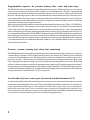
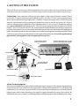
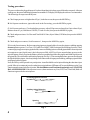
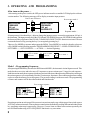
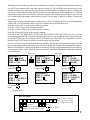
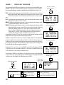
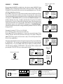
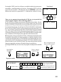
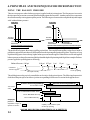
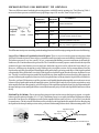
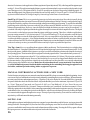
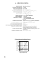
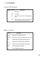
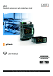
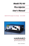
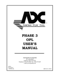
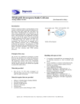
PROGRAMMABLE
MICROINJECTOR
PM 2000
USER'S
INSTRUCTION MANUAL
12345678901234567
12345678901234567
12345678901234567
MDI
TABLE OF CONTENTS
INTRODUCTION ---------------------------------------------------------
1
1. SETTING UP THE SYSTEM ---------------------------------------Connection
3
About the micropipette 3
Testing procedure
4
3
2. A CLOSER LOOK AT THE INJECTOR -----------------------Front Panel
5
Rear Panel
6
The Key Pad
6
5
3. OPERATING AND PROGRAMMING --------------------------After turn on the power
8
Mode 1 : AUTO. SEQUENCE
8
Mode 2 : PRESSURE MONITOR
10
Mode 3 : TIMER
11
Mode 4 : COUNTER
12
Mode 5 : ACTION
12
8
4. PRINCIPLES AND TECHNIQUES FOR MICROINJECTION - 14
Using The Balance Pressure
14
Microinjection for Different Tip Openings
15
Manual Control Actions for a New User
16
Saving Gas
16
5. MAINTENANCE AND TROUBLESHOOTING ---------------
17
6. SPECIFICATIONS -----------------------------------------------------
18
7. ACCESSORIES ---------------------------------------------------------
19
8. WARRANTY -----------------------------------------------------------
20
MDI 6/01 , IMA S/W:V8.3
INTRODUCTION
A superior device for microinjection and intracytoplasmic sperm injection
The advantage of semi-automatic cell microinjection has changed the way that the scientists carry out in biomedical
research. The used test tube experiments and in vitro fertilization ( IVF ) can be performed in a single cell now. In
the context of proper injection controls, modulation of cellular processes can be dissected in an unambiguous and
rapid manner, not only accelerating the understanding of the molecular control of cell physiology, but also clarifying
the ever present problem of cause-and-effect in the complexity of biological systems. The microinjection has been
a cost-effective, simple and powerful new technology. The use of microinjection has rapidly grown and is expected
to become a major molecular and cellular technique in near future. Equipped with an advanced microcomputer and
precise pneumatic components, the PM2000 MICROINJECTOR is just designed to satisfy scientists' every
requirement during microinjection. It is a superior device for cell microinjection, intracytoplasmic sperm injection
( ICSI ) and cell electrophysiology. For the Cell Microinjection, the PM2000 can be used to inject any type of
molecule or combination of molecules into the cytoplasm or nucleus. For example, RNA, DNA, proteins, antibodies,
labelled dyes, synthetic molecules, peptides, and cell organelles all can be injected. Cell holding, transferring and even
chromosome dissection can also be performed. The PM2000 can deliver from picolitter to unlimited wide range
of liquid to a target. For the Intracytoplasmic Sperm Injection ( ICSI ), the PM2000 can be controlled precisely
to pick up and transfer sperm. With a smooth and very fine adjustable suction, ejection pressure and a computerize
timing valve, even a single sperm can be handled conveniently and precisely.
Complete capabilities for cell microinjection and suction
A 60 - 100 psi pressure input gas is the only gas source required for the PM2000 to produce a wide range of pressure
and vacuum outputs. There are two output ports on the PM2000 front panel, one for a cell holding pipette and
another for a cell injection (or suction) pipette. The PM2000 has been equipped with not only injection and balance
pressure regulators but also hold and fill (suck) vacuum regulators. Both pressure and vacuum are individually
controllable.
There are a total of eight different functions in the PM2000. Four of eight functions ( clear injection pipette, clear
holding pipette, suction in the inject pipette and injection in the inject pipette ) are programmable. Two functions
control cell holding ( vacuum for holding a cell, stop vacuum for releasing a cell ) and other two functions for balancing
capillary action of injection pipette ( on / off the pressure for the balance ). The clearing pipette applies input gas
pressure and activate programmable timer and counter parameters to clear injection pipette. The Clear Hold function
applies adjustable hold pressure to push a cell out of the holding pipette or just clear the Hold Pipette. Fill function
( suction ) generates a regulated vacuum and activates its programmable timer and counter parameters to fill the
injection pipette from the tip. The inject function applies regulated pressure and programmable timer and counter
parameters to perform precise ejection. All four programmable timing functions can be manually controlled or
interrupted by pressing AUTO key , foot switch or input an external TTL signal during their actions. A precise actual
action time will be displayed after an interruption and let the user to calibrate liquid volume easily. Three BNC
connectors, corresponding INJECT, FILL actions and auto-sequence TRIGGER, provide electrical TTL outputs
and input for external synchronizing and recording.
1
Programmable sequences for pressure memory, time, count and action steps
The PM2000 allows the user to program custom-designed action sequences. Within each sequence, a user can save
4 preset pressure readings, preset 4 timers and 4 counters for corresponding actions. There are 12 programmable
action steps in each sequence and total 63 programmable sequences. All 63 sequences will be saved even turn off
the power. The last using sequence will be recovered automatically when turn on the power again. Therefore, a user
can program all different pressures, timers, counters and action steps for different experiments ( up to 63 ). The user
can just turn on the power to continue the last experiment , or simply select a sequence number, any one of 63 different
experiments can be precisely repeated on any time.
In each sequence, the four timers and four counters are preset individually for four actions (CLEAR, CLEAR HOLD,
FILL and INJECTION ). The time range can be set from 10 millisecond to 327 second in 10 msecond resolution
for the whole range. The counter function provides a way to add up calibrated volumes. Up to 12 programmable
steps in each sequence give the user versatile sequential injection or suction cycle. By pressing the foot switch, AUTO
key or input an external signal to the TRIGGER BNC during action mode, the PM2000 will perform sequential preset
action step by step. The sequence cycle can be constantly repeated and the user can manually interrupt the sequence
at any step. This auto-sequence function will give a user many convenience in controlling different microinjection
cycles and ensure that all cycle conditions are absolutely identical. Users will find this function is also very useful for
multi-cell injection or suction.
Pressure, vacuum, counting and action time monitoring
The PM2000 performs real-time data acquisition for pressure and vacuum monitoring. In the pressure mode, user
can immediately see display of Fill vacuum generator pressure, Injection pressure, Balance pressure and Hold
vacuum or monitor the input pressure. During the pressure mode, user can adjust four regulators to preset four
pressures ( vacuums ). There is memory for saving all four preset pressure readings in each sequence. By pressing
a key to display previous pressure settings, the user can compare present setting with the previous ones. By pressing
another key, the present pressure readings will update the memory and be saved. During operations of action mode,
the operating pressure is monitored and is real-time displayed in the corner of the LCD. Meanwhile, the action timer
count down is also displayed in the LCD. If a manual interruption happens, the actual action time will be displayed.
A displayed number records the INJECT or FILL acting count.
User-friendly keyboard, remote port, foot switch and full information LCD
A simple and straightforward 4x4 keyboard allows the user to preset timer, counter and action sequences, monitor
pressure and vacuum and perform actions. An LCD provides full information display such as pressure, vacuum, time,
count, sequence steps and actions, etc. The remote port of a DB9 connector gives users a very useful option to
interface the outer control unit. There is an optional remote keypad can be plugged in this remote port, let a
microscope operator can combine to set up a very convenient microinjection work station. Another function of the
remote port is as a computer interface port for cell electrophysiology applications.
2
1. SETTING UP THE SYSTEM
There are different system set up for different applications. An experienced user can set up a perfusion system as
well as an injection system with this injector. The following is only an example of a microinjection system set up:
Connection: Connect the power cord to an AC outlet with the voltage as specified on the rear panel. There is
a GAS INPUT Connector on the rear panel (See REAR PANEL). Screw the 1/8" Hose Connector into the Pressure
Input Connector and connect to a gas supply with a 1/8" ID hose. Compressed air supply source is suitable for oxygen
insensitive injection material. Inert gas nitrogen is suitable for air sensitive material. A pressure of 60 - 100 psi is
sufficient. An input pressure of higher than 110 psi will damage the device. Any very active, flammable or corrosive
gas is not recommended for the input gas source. There are two gas output ports on the front panel (See FRONT
PANEL). There are two inserts with 1/16" ID ( or other smaller ID ) hard wall tubbing which will prevent pressure
be buffered to the pipettes. Put one of inserts into the Hold Output port and connect its tubing to the holding pipette
holder. Put another insert into the Injection Output port and connect its tubing to the injection pipette holder. Don't
connect micropipettes to the pipette holders before blowing the tubing and holder. Never let the injection tubing,
pipette holder, holding pipette or injection pipette point to a person.
Inje
ct O
utp
ut T
ubin
g
Pipette Holders
Three-Axis Hydraulic Micromanipulator
Connect to a pressure
source ( 50-100 psi )
Ho
ld C
ell
Ou
tpu
t Tu
bin
g
Connect the power cord to a AC
power outlet as specified voltage
PM2000 Microinjector
Joystick Hydraulic
Micromanipulator
Optional Remote Key Pad
Inverted Microscope
Injection Pipette
Foot Switch
Cell Holding Pipette
About the micropipettes :
Microinjection technique also requires skills in making and using micropipettes. Micropipettes ranging inside tip
diameter from 0.20-5.0 um can be formed by a pipette puller. Change in inside tip diameter 10% will change fluid
conductance by 30%. Therefore, larger tip will deliver more material but easy damage to the cell. Smaller tip need
higher pressure to deliver material and easy to be clogged. A pipette with smaller tip can inject few picoliters, the
smaller tip the more precise control. For cell holding, the tip of a pulled micropipette must be polished by a microforge.
3
Testing procedure :
The power cord must be plugged into an AC outlet with an identical voltage as specified on the rear panel. After turn
on the power, the power indicating light must be on and the LCD display will display the software version number.
The followings are steps to use the injector :
A. Check input pressure no higher than 102 psi , let the buzzer on, then press the MODE key;
B. It is Sequences mode now, ignore this mode in the first testing, press the MODE key again;
C. It is Pressure mode now. Check and adjust pressures, adjust Fill pressure to about 60 psi, Inject about 30 psi,
Balance about 0.3 psi, Hold about 15 iH2O (12 inch of water), then press the MODE key again;
D. Check and preset timers. Set Clear and Clear Hold 10-20ms, Inject 100ms, Fill 500ms, then press the MODE
key again;
E. Check and preset counters, Set all counter to 1, then press the MODE key again;
F. It is ready for actions now. Before connecting pipettes to pipette holders, be sure the pipette or tubbing opening
does not point to a person. Use Clear ( CLR ) and Clear Hold ( CLRH ) function to blow tubbing few times. Then,
connecting inject pipette to inject pipette holder, connect cell hold pipette to cell hold pipette holder. Insert injection
micropipette to some liquid (water), don't forget press BALANCE key first to output balance pressure to the
injection pipette. Slowly increase the balance pressure to push the liquid out of the pipette until all the liquid just out
the pipette tip. The air should be stable in the pipette tip (See Fig. 1). If increasing the balance pressure doesn't push
the liquid inside the pipette, check any leakage at all connections of output port to tubbing, tubbing to pipette holder
and pipette holder to pipette.
Now, the INJ key can be pressed to try an injection. A small air bubble can be injected during the short time inject
period. If the air is continue injected even the inject action indicator LED turns off, be sure the Balance or the Vent
function must be turned on before injection. For detail Balance and Vent function principle, see USING THE
BALANCE PRESSURE. If the injection is correct, then continue to try Vent , Fill, Clear, Clear Hold, Hold cell
functions to get used to the microinjector.
Increasing Balance Pressure
to push >>>
Capillary Action Balancing
Injecting
Fig. 1
4
2. A CLOSER LOOK AT THE INJECTOR
FRONT PANEL :
1 HOLD Vacuum Control
Used to adjust and set HOLD vacuum for HOLD
OUTPUT port.
10 INJ.SYN.OUTPUT Signal Output BNC
Produces negative synchronous TTL signal output
during injection at the FILL/INJ. OUTPUT port.
2 BALANCE Pressure Control
Used to adjust and set BALANCE pressure for
INJ.OUTPUT port.
11 FILL SYN.OUTPUT Signal Output BNC
Produce negative synchronous TTL signal output
during suction at the FILL/INJ.OUTPUT port.
3 INJECT Pressure Control
Used to adjust and set INJECT pressure for
INJ.OUTPUT port.
4 FILL Vacuum Control
Used to adjust and set supply pressure of FILL
vacuum for INJ.OUTPUT port.
5 LCD Display Window
Displays real-time pressure, vacuum, time, count and
total information for programming.
6 Control Keyboard
Used to program and control the microinjector.
7 Power Switch and Indicator
Press the switch to turn power on, press again to trun
power off. The power indicator LED displays the power
on or off.
8 HOLD OUTPUT Port Connector
Connect the tubbing insert. Holding vacuum and clear
pressure for the holding pipette are delivered from this
port.
9 FILL/INJ. OUTPUT Port Connector
Connect the tubbing insert. The injection, balance, fill
and clear pressures for the injection pipette are delivered
from this port.
12 TRIGGER INPUT Signal Input BNC
Input a negative TTL signal to this BNC as a sequential step trigger. It performs the same function as AUTO
key on the keyboard and the same function as the foot
switch.
13 Action Indicating LEDs
Indicate CLEARing, CLEARing HOLD, HOLDing,
BALANCing, FILLing and INJECTing actions.
14 INJ Foot Switch Jack Port
Connect a foot-switch or other handy switch with a
3.5mm plug into this jack port to perform the same
function as pressing the INJ key on the key board.
15 AUTO Foot Switch Jack Port
Connect a foot-switch or other handy switch with a
3.5mm plug into this jack port to perform the same
function as pressing the AUTO key on the key board.
16 REMOTE Key Board PORT DB9 Connector
Connect an optional remote keyboard to this port to
perform convenient remote control.
5
REAR PANEL :
3
4
1
1 AC POWER INPUT Connector
Connect the power supply cord and plug in an AC
power outlet same as the specified voltage.
2 GAS INPUT Port
Connect the 1/8" tubing connector for compressed
gas input.
5
2
3 Fuse Box
Replace with the same rating and size fuse only.
4 Gas Filter View Hole
Check filter bowl from this hole.
5 Filter Drain Hole
On the bottom panel as indicated. If accumulated
liquid is found in the filter bowl, press the drain valve
through the hole to drain out liquid.
The Key Pad
Press to turn off input pressure and halt the mode,
A
S
MODE
C
P
R
P
T
on s/ms
P off
VENT
STOP
AUTO
ST
ST
SEQ
SEQ PS
0
1
10
100
CLR RELB
RELH CLRH
BALN
HOLD FILL
INJ
The Key Functions :
A
S
MODE P
C
6
T
Press to change MODE : form SEQUENCE
to PRESSURE to TIMER to COUNT to
ACTION then going back to SEQUENCE
...
on
P off
press again to recover mode and pressure.
s/ms
VENT
Press to select unit second or unit millisecond
during TIMER mode. Press to set or cancel a
VENT function in the SEQUENCE mode. Press
to open or close a vent hole in the inject port during
ACTION mode. An opening vent hole will be
display as ' V ' next to the 'ACTION:' on the LCD
display. An opening vent hole will provide a
channel of atmosphere to the injection port. Therefore, any balance, injection or suck pressure in the
injection port will be reduced or bypass by the
vent hole. ( See TIPS AND TECHNIQUES for
detail application ).
STOP
AUTO
P
R
ST
0
ST
1
SEQ
10
SEQ PS
100
CLR
RELB
Press to set the last step and as a sequence
repeating step during SEQUENCE mode. Press
to trigger an auto-sequence step or interrupt an
action during ACTION mode.
Press to disable the buzzer during the power on
display. Press to display previous pressure reading memory in the PRESSURE mode. Press to
select a step (down number) for the SEQUENCE
mode. Press to reset number for TIME mode
and COUNT mode. Resetting timer is also
setting the timer to MANUAL control.
RELH
CLRH
Press to enable the buzzer again during the
power on display. Press to select a step (up
number) for the SEQUENCE mode. Press to
add 1 to the number for TIME mode and COUNT
mode.
Press to select a sequence (down number) for
the SEQUENCE mode. Press to add 10 to the
number for TIME mode and COUNT mode.
Press to save pressure reading to the memory in
the PRESSURE mode. Press to select a sequence (up number) for the SEQUENCE mode.
Press to add 100 to the number for TIME mode
and COUNT mode.
Press to select CLEAR function for SEQUENCE, TIME and COUNT mode. Press to
display input pressure from PRESSURE mode.
Press to generate the CLEAR function during
ACTION mode. This function will clear the
injection pipette, input source pressure is directly
used and controlled by its timer and counter. This
function will help to avoid the injection pipette
from being clogged.
Press to select RELEASE BALANCE function
for SEQUENCE mode. Press to turn off the
Balance function during ACTION mode. This
function will shut off the injection port from the
BALANCE pressure. Press again will open
balance pressure for a pulse of 9 millisecond then
closing again.
INJ
BALN
HOLD
FILL
Press to select RELEASE HOLD function
for SEQUENCE mode. Press to turn off the
Hold function during ACTION mode. This
function will turn off the hold cell vacuum from
cell hold port and release the held cell.
If the cell is still attaching the holding pipette
even after releasing holding vacuum, the CLRH
key can be press to push the cell away. The
pushing pressure can be adjusted from the
HOLD pressure regulator and controlled by
its timer and counter. The CLEAR HOLD
function also can be used to clear the holding
pipette during ACTION mode. Press to select CLEAR HOLD function for the SEQUENCE, TIME and COUNT mode. Press
to display Hold pressure/vacuum from PRESSURE mode.
Press to select INJECT function for SEQUENCE, TIME and COUNT mode. During ACTION mode, press to generate an
injection which is controlled by its timer and
counter, the adjustable INJECT pressure is
delivered to the injection pipette.
Press to select BALANCE function for SEQUENCE mode. During ACTION mode,
press to deliver an adjustable BALANCE
pressure to the injection pipette to balance
capillary action.
Press to select HOLD function for SEQUENCE mode. During ACTION mode,
press to generate an adjustable hold cell
vacuum to the holding pipette to grasp a cell
on the polished tip.
Press to select FILL function for SEQUENCE,
TIME and COUNT mode. During ACTION
mode, press to generate a suction vacuum,
which is controlled by its timer and counter.
The adjustable suction vacuum is delivered to
FILL the injection pipette.
7
3. OPERATING AND PROGRAMMING
After turn on the power ...
After turning on the power switch, the LED power indicator must be on and the LCD displays the software
version number. The following message will be display to monitor input pressure:
Press to turn off buzzer.
P
R
INPUT/CLEAR
PRESSURE
100 psi
BUZZER ON
ST
> INPUT/CLEAR
0
<
Press to enter mode 1.
A
C
PRESSURE
100 psi
BUZZER OFF
ST
1
S
MODEP
T
V
Sequence mode ...
Press to turn on buzzer.
If input pressure is less than 60 psi., adjust or change the input gas source to meet the requirement. 100 psi. is
the maximum. The input pressure also is the CLEAR and CLEAR HOLD pressure. BUZZER ON indicates that
the buzzer will beep when one of the CLEAR, CLEAR HOLD, INJECT or FILL function is activated. The user
can turn the buzzer off by pressing the key 0, or on again by pressing key 1.
There are five MODEs to operate and program the IM300. Press MODE key on the keyboard to select one
of five MODEs as the following sequence: PROGRAMMING SEQUENCE-----DISPLAY PRESSURE----SET TIMER-------SET COUNTER------ ACTION-------back to beginning.
Keys for power just on condition:
P
R
ST
0
Press to disable
the buzzer.
ST
1
Press to enable
the buzzer.
A
S
MODEP Press
C
T
to mode 1.
Mode 1 : Programming Sequences
After pressing the MODE key one time, the IM300 enters MODE 1, the Automatic Action Sequence mode. This
mode lets the user review and select one of 63 sequences or preset actions up to 12 steps for each sequence..
In the later action mode, these sequences let the user activate functions without pressing different keys and repeat
the action sequence cycle conveniently. Besides 12 action steps, four timers, four counters and pressure reading
can be saved in the memory for each sequence. The pressure reading is on the next mode. The programming
of timers and counters will be described in third and fourth modes.
Press to upper sequence.
SEQUENCE 1:
STEP 1 : CLEAR
STEP 2 : CLR.HOLD <
STEP 3 : FILL
SEQ
100
SEQ
10
>
SEQUENCE 2:
STEP 1 : INJ
STEP 2 : INJ
STEP 3 : INJ
Press to lower sequence.
Presetting an action on each step will let a user activate actions step by step with just press foot switch or press
AUTO key in later action mode. If a user plans to control actions by manually pressing different individual action
key, presetting action step is unnecessary. However, if a user wants to control some actions repeatedly, the
user will find out that using AUTO. SEQUENCE function is very convenient.
8
When the power is turned on, the unit will recover the previous sequence which performed before the unit power
was off. If a user wants to edit or use other sequence setting, key 100 (up SEQ) can be pressed to go up the
sequence number or key 10 (down SEQ) to go down the sequence number. Changing a sequence will not only
give the user a different action steps, but also will give the user different pressure reading memory, different
setting timers and counters which will be reflected on other modes. In other words, the injector can store up
to 63 complete different settings which include 63 sets of 12 action steps, 63 pressure readings, 63 timers and
63 counters.
There are up to 12 programmable steps in a sequential cycle. The LCD displays the first 3 steps in the beginning
of this mode. The cursor blinks on first step row to indicate the current edited step row.
Press key 0 (down ST) to go down the edited step number.
Press key 1 (up ST) to go up the edited step number.
Press key 10 (down SEQ) to go down the sequence number.
Press key 100 (up SEQ) to go up the sequence number.
Press one of the CLR, RELB, RELH, CLRH, INJ, BALN, HOLD, FILL and VENT(s/ms) keys to preset
corresponding function in the current edited step. Press the same key again will cancel the setting on that step.
Pressing the VENT(s/ms) key will preset the VENT function step. First VENT step will open the vent hole,
then the second VENT step will close the vent hole (toggle key operating).
Press key AUTO to preset return function in the current step. This function will cause the first step to become
the next step and repeat the sequential step cycle. Therefore, the step AUTO must be the last step of the sequence.
Whenever finishing the 12th step during the action mode, the first step will be automatically become the next
step (automatic repeat cycle). Therefore, a user can set all 12 steps with actions and can repeat the action step
cycle without end.
SEQUENCE 1:
STEP 1 : CLEAR
STEP 2 : CLR.HOLD
STEP 3 : FILL
Press to
set Inject.
Press to
next step.
ST
1
SEQUENCE 1:
STEP 1 : CLEAR
> STEP 2 : CLR.HOLD
STEP 3 : FILL
Press to set
Clear Hold.
INJ
V
SEQUENCE 1:
STEP 1 : INJ
STEP 2 : CLR.HOLD
STEP 3 : FILL
Press to previous step.
P
R
ST
0
SEQUENCE 1:
STEP 1 : CLEAR
> STEP 2 : CLR.HOLD
STEP 1 : CLEAR
Press to
set Vent.
CLRH
V
SEQUENCE 1:
STEP 1 : CLEAR
STEP 2 :
STEP 3 : FILL
s/ms
VENT
V
SEQUENCE 1:
STEP 1 : CLEAR
STEP 2 : CLR.HOLD
STEP 1 : VENT
Press to
n e x t
mode.
A
S
MODEP
C
T
V
Pressure mode ...
Keys for Mode 1 :
s/ms STOP Press to preset a function
CLR RELB RELH CLRH INJ BALN HOLD FILL VENT
AUTO on the step, press the same
key will cancel the function
P ST
SEQ
SEQ Press to select
ST Press to select
R
100
10
0
1 a step.
a sequence.
on
Poff
Press to turn off input pressure and
halt the mode, press again to recover.
A
S
MODEP
C
Press to mode 2.
T
9
MODE 2
PRESSURE MONITOR
By pressing the MODE key second time, the injector enters MODE 2 from
MODE 1. The fill vacuum generator pressure, injection pressure, balance
pressure and holding vacuum are simultaneously displayed on the LCD.
Press to enter
pressure mode.
A
S
MODEP
T
C
FILL - Monitors the supply pressure for the fill vacuum generator, real-time
displays the change while adjusting Fill supply pressure control. Refer
to the Fill Vacuum / Flow Characteristics for actual vacuum conversion..
INJ - Monitors the injection pressure, real-time displays the change while
adjusting the Inject pressure control.
BALN - Monitors the balance pressure, real-time displays the change while
adjusting the Balance pressure control.
HOLD - Monitors the holding vacuum, real-time displays the change while
adjust the Hold vacuum control. The actual vacuum will be displayed
while the holding action is on. The actual vacuum will be more
negative than the displayed number when the displayed number is
larger than 3 (-iH2O). If the holding action is off, the displayed
vacuum will be more negative than the actual vacuum.
Pressing the 0 (down ST) key, the previous saved pressure readings will be
displayed on the right side of the monitored pressure.
With the comparison of previous memory reading, the user can adjust the
pressure controls to the same number as before to ensure the identical pressure
condition. If a user want to up date the present pressure setting to the memory,
just simply pressing the 100 (up SEQ) key, all current pressure readings will
be stored into the current sequence memory.
Pressing CLR keys while in the MODE 2, the LCD will display INPUT/
CLEAR pressure. Pressing one of the FILL, INJ, BALN and HOLD keys, the
LCD will back to four pressure monitor above.
Pressing the CLRH key will display Clear Hold pressure as well as Holding
vacuum. They are controlled by the same Hold regulator. The higher Holding
vacuum is set, the higher Clear Hold pressure will be.
Press to display other
pressures.
Press to next mode.
A
S
P:FILL 60.0
psi
INJ 20.5
psi
BALN 2.5
psi
HOLD 3.2 -iH2O
P
MODE
C
T
V
Timer mode ...
Press to display previous
pressure reading memory.
Press to display inPress to mode 3. CLR CLRH
put/clear pressure.
Keys for Mode 2:
A
S
MODEP
C
10
T
P
R
ST
0
<
INJ
V
P:FILL 60.0
psi
INJ 20.5
psi
BALN 2.5
psi
HOLD 3.2 -iH2O
Press to display
pressure memory.
P
R
ST
0
V
P:FILL 60.0 M 50.0
INJ 20.5 M 10.0
BALN 2.5 M 1.0
HOLD 3.2 M 5.0
Press to save pressure measurement.
SEQ PS
100
V
P:FILL 60.0 M 60.0
INJ 20.5 M 20.5
BALN 2.5 M 2.5
HOLD 3.2 M 3.2
Press to display input/
clear pressure.
CLR
V
INPUT/CLEAR
PRESSURE:
100 psi
SEQ PS Press to store present pressure
100 reading to the memory.
on
Poff
Press to turn off input pressure and
halt the mode, press again to recover.
MODE 3
Press to enter timer
mode.
TIMER
By pressing the MODE key third time, the injector enters MODE 3 from
MODE 2. The LCD displays all four timers. Press one of the CLER, CLRH,
INJ and FILL keys to move the cursor on corresponding timer row. The timer
will determine the action time.
Press s/ms (VENT) key to select unit second or unit 10 millisecond. Press
key 0 to reset the timer and the reset timer also means the action can be
controlled manually by pressing the action key without timer control, which
is displayed as 'MANUAL 0s' for second unit and 'MANUAL 0m' for 10
millisecond unit. Press key 1 to add 1 into the timer. Press key 10 to add 10
into the timer. Press key 100 to add 100 into the timer. The maximum time
setting for each timer is 327.66 seconds. More than 327.66 seconds setting
will turn the timer to be CONTINUE, displayed as ' CONTINUEs(m)',
which means that action will be acting continually until the STOP/AUTO key
being pressed.
Example of setting 125.38 sec. for CLEAR :
Press CLR key to move the cursor on CLR row.
Press s/ms (VENT) key to display 'sec'. Press 0 key to reset the timer. Press
100 key one time. Press 10 key two times. Press key 1 five times. Then press
s/ms (VENT) key again ( convert to msc. unit ). Press 100 key three times.
Press 10 key eight times.
If manual controlled action time is needed, just press 0 key to reset the timer
to 'MANUAL0'. The action time will depend on the time of pressing and
holding the key. Or, press s/ms (VENT) key to display 'sec' then press key
100 four times to display 'CONTINUEs'. The action will be continue until
pressing the STOP/AUTO key to interrupt the action.
T: CLR
0.01sec
CLRH
0.01sec
FILL
0.01sec
INJ
CONTINUEs
Press to next mode .
A
S
Keys for Mode 3 :
S
MODEP
C
T
Press to mode 4.
T: CLR
10msec
CLRH
10msec
FILL
10msec
INJ CONTINUEms
CLR CLRH INJ
P
R
ST
ST
SEQ
0
1
10
T
V
T: CLR
CLRH
FILL
INJ
0.01sec
0.01sec
0.01sec
0.01sec
Press to reset timer.
P
R
ST
0
V
T: CLR
0.01sec
CLRH
0.01sec
FILL
0.01sec
INJ
MANUAL 0s
Press 4 times to maximum.
SEQ PS
100
V
T: CLR
0.01sec
CLRH
0.01sec
FILL
0.01sec
INJ
CONTINUEs
Press to
Fill timer.
<
FILL
Press to
change
time unit.
T
V
Counter mode ...
S
MODEP
C
MODEP
C
A
A
<
s/ms
VENT
Press to select one s/ms Press to select unit second
of four action timers. VENT or unit millisecond.
P
SEQ S Press to add number
on Press to turn off input pressure and
Poff
100 on the timer.
halt the mode, press again to recover.
FILL
11
MODE
4
COUNTER
Press to enter counter mode.
By pressing the MODE key fourth time, the injector enters MODE 4 from
MODE 3. The LCD displays all four counters.
S
A
MODEP
Press one of the CLER, CLRH, INJ, and FILL keys to move the cursor on
T
C
corresponding function row. The counter will determine how many times the
V
action occurred in each action trigger (manual and sequential). If the user
1
calibrates the unit delivery for injection or suction under certain pressure and COUNT: CLR
CLRH
1
time, the counter can be easily used to calculate more delivery.
FILL
1
Press key 0 to reset the counter.
INJ
1
Press key 1 to add 1 into the counter.
Press key 10 to add 10 into the counter.
Press to add one.
Press key 100 to add 100 into the counter.
The maximum count setting for each counter is 255.
ST
1
Press to Fill
counter.
Press to next mode.
A
COUNT: CLR
CLRH
FILL
INJ
S
MODEP
C
T
V
Action mode ...
1
1
1
2
<
ST
ST
SEQ
0
1
10
FILL
V
COUNT: CLR
CLRH
FILL
INJ
1
1
1
2
Keys for Mode 4 :
Press to select one
of four action
counters.
on Press to turn off input pressure and
Poff
halt the mode, press again to recover.
CLR CLRH INJ
MODE 5
FILL
P
R
A
SEQ PS Press to add num100 ber on the counter.
S
MODEP
C
T
Press to mode 5.
ACTION
Pressing the MODE key fifth time, the injector enters the last mode MODE 5 from
MODE 4. The message 'ACTION' will be displayed on the LCD and the input
pressure is monitored on the right side of the message.
In this mode, the user can press one of the CLR, RELB, RELH, CLRH, INJ,
BALN, HOLD, FILL and VENT (s/ms) keys to generate different action. The
CLR, CLRH, INJ and FILL functions are determined by the their presetting timer,
counter and control pressure. During their actions, the operating pressure is
displayed instead of input pressure. Therefore, instant action pressure adjustment is possible during action mode. If the preset timer is longer than 1 second,
the timer countdown will be displayed on right side of the function name. If INJ
or FILL function acting, besides timer countdown, a number will be displayed
on the side of function name. The number records the count of function continued
acting. The INJ acting resets the FILL counting and the FILL acting resets the INJ
counting. A CLR acting resets both two counts.
The HOLD, RELH, BALN and RELB functions are manual control and pressure
adjustable only. There are no timer countdown display for these actions. Their
actions and CLRH acting will not affect the INJ or FILL counting number.
12
Press to enter action mode.
A
S
MODEP
C
T
V
ACTION : <- 100 psi
Press to trigger
FILL function.
FILL
V
ACTION : <- 100 psi
FIL--1
10.55sec
Pressing the VENT (s/ms) key will open a vent hole inside the injection port to
atmosphere, a small bypassing way to the air. Pressing the VENT (s/ms) key
again will close the hole. A 'V' displayed after the 'ACTION: 'on the LCD
indicates the vent hole is opened and a '<-' indicates the vent hole is closed.
There are two purposes by pressing the AUTO key (or step on the foot
switch or input a negative TTL to the Trigger BNC ) :
A. The AUTO key is a trigger for a sequence step during Action Mode.. If many
identical cell injections are needed, or eyes are busy on the scope, the user can
just press AUTO key to follow the preset sequential action steps. Press AUTO
key one time for one step. Or, just step on a foot switch which is connected to
the AUTO FOOT SWITCH jack. It will perform the same function as the AUTO
key. Any action key can be pressed to insert a function between two sequential
steps. The control will be back to the sequence by pressing AUTO key or foot
switch again. If an action is one of the CLR, CLRH, INJ and FILL functions, their
timer countdown will be displayed on right side of the function name.
B. During timer action, pressing the AUTO key will interrupt and stop the action
immediately. Meanwhile, the actual action time is displayed instead of time
count down. Setting the timer to 'CONTINUEs(m)' or long enough time, a user
can manually control action time by pressing the AUTO key to break the action.
When the timer is set to 'MANUAL 0s(m)', the action only performs with the
finger pressing the key and turn off when the finger leaving the key.
Pressing the MODE key one more time, the program will jump back to MODE
1.
Vent closed
ACTION : <- 100 psi
Press
open
vent.
s/ms
VENT VENT
Vent opened
Press to trigger the step
function of the sequence.
AUTO
first mode.
A
S
MODEP
C
T
V
ACTION : <- 30 psi
INJ--1
0.85sec
AUTO-SEQUENCE:
STEP 2 : REL. BAL
Press to stop/interrupt the action.
<
STOP
AUTO
or
foot switch
Press
to close
vent.
V
ACTION : V 100 psi
STOP
Press back to
s/ms
or
foot switch
V
ACTION : <- 100 psi
AUTO-SEQUENCE:
STEP 1 : INJECT
Sequence mode
s/ms Press one of function
CLR RELB RELH CLRH INJ BALN HOLD FILL VENT
keys to generate an action.
S
Press to trigger an auto-sequence
A
on Press to turn off input pressure and
MODEP Press back to mode 1. STOP
Poff halt the mode, press again to recover.
AUTO step or interrupt a manual action.
T
C
Keys for Mode 5 :
13
4. PRINCIPLES AND TECHNIQUES FOR MICROINJECTION
USING THE BALANCE PRESSURE
There are two purposes when a balance pressure is applied to the injection pipette. The first purpose is to restrict
the inject pressure or suction vacuum to be buffered in the pipette after an action. . Another purpose is to compensate
the suction caused by a micropipette capillary action. The following two characteristics compare the injection output
with / without balance pressure:
INJECTING
PRESSURE
INJECTING
PRESSURE
PRESET
PRESSURE
PRESET
PRESSURE
BALANCE
PRESSURE
BALANCE
PRESSURE
TIME
INJECTION
PRESETTIME
TIME
INJECTION
PRESETTIME
Injection with balance pressure will
turn off at the correct timing.
PRESSURE
BUFFEREDTIME
Injection without balance pressure will continue inject
for some time even the injection valve is turned off.
The smaller ID of a pipette, the stronger capillary action it has. There are different capillary action forces inside a
pulled micropipette because there are different IDs from the tip to unpulled portion of a pipette. Therefore, to keep
liquid inside a pipette closer to the tip, higher balance pressure must be applied. Other factors to effect the applied
balance pressure are the surface tension of the liquid and the depth of tip inserting in the liquid. An example of balance
pressure applied to a pulled pipette as following :
Balance Pressure: 0.06 psi
0.06 psi 0.35 psi
1 psi
1.5 psi
3 psi
4.5 psi
0.58 mm I.D.
1 mm O.D. pipette
10 um tip opening
The liquid boundary
The pulled pipette can be precisely controlled to suck or inject by the microinjector. The following characteristic
chart shows the princeple of suction or ejection corresponding to different valve action for the pipette above:
<
Suction from the pipette tip
> < Ejection from the pipette tip >
Turn on INJECT valve
Turn on FILL
valve
Turn on BALANCE and VENT valves
Turn on BALANCE valve only
Turn on VENT valve only
Output port
pressure : -20" Hg
0 0.2 psi 4.5 psi
Adjustable range of
ejection or suction :
10 psi
^
Capillary action balance point
at 10um tip opening
SUCTION AND EJECTION CHARACTERISTIC OF A PIPETTE TIP
14
20 psi
MICROINJECTION FOR DIFFERENT TIP OPENINGS
There are different control methods when using pipettes with different tip opening size. The following Table 1
measures balance pressures with different tip opening or taper I.D. in water, from 0.06 psi to 50 psi.
TAPER I.D. or
TIPOPENING
BALANCE
PRESSURE
Unpulled(0.6mm)
0.06 psi
180 um
0.18 psi
100 um
Tip
section 10 um
0.35 psi
COMMENT
Vent should be turned on as well as setting
balance to minimum
Tip
Unpulled
section
Taper
section
Adjusting balance manually will back and forward the solution inside the taper.
4.5 psi
2.5-1 um
10 - 25 psi
< 1 um
26 - 50 psi
Good for quantitative injection.
For very sensitive agent test or injection.
TABLE 1
The different microinjector controlling methods and applications for different tip openings are discussed as following:
Larger Tip (>200 um) or Unpulled Section of a Pipette: There is very rare to need a pipette opening larger than
200 um, because the injected volume is big even with the small injection pressure and is hardly controlled precisely.
The balance pressure is very low, usually <0.1 psi, even turning the Balance pressure to minimum is still too high.
In this case, the Vent function must be pressed on. The Vent function actually opens a vent hole inside the injection
channel to bypass some balance pressure and cause the balance pressure can be adjusted to lower than 0.1 psi.
However, with larger tip, the pipette is easily filled up just by its capillary action. Always turn on balance first, the
liquid can be sucked by pressing on Fill and liquid can be pushed out by pressing on the Inject. If the liquid is pushed
out again after filling, the balance is too high. If the liquid is sucked back again after the injection, the balance is too
low. Usually, because the injection pushes the liquid all the way from unpulled section to out of tip of the pipette, the
pressure balancing the unpulled section is too low to keep the balance on the tip, then the liquid will be sucked back.
Therefore, perform Fill function or capillary action to suck liquid higher than the unpulled section, then set correct
balance to keep liquid stable inside the unpulled section. Now the liquid can be freely sucked in or pushed out only
in the unpulled section of the pipette by press Fill or Inject. If the small amount liquid can only be played around inside
the taper and tip section, turning the balance control knob manually only will move the liquid back and forward from
the tip.
Medium Tip (10-100 um): The suction and injection principles are the same as the larger tip pipette, except the
balance pressure at the tip is higher (4.5 -0.35 psi). This balance range is covered by the Balance adjustment without
turn on the Vent. However, the balance pressure for the unpulled section is still very low (<0.1psi), the Vent should
be turned on too. The Inject and Fill functions still work only for the liquid inside the unpulled section. But playing
the liquid inside the taper and tip section can be performed with turning Balance knob without turning on the Vent
Unpulled section
Taper section
Holding Pipette
Media drop with target cell
Tip section
1234567
1234567
1234567
Injection Pipette
123456
123456
123456
123456
Solution or agent drop to be sucked then injected
15
function. For instance, in the application of Intracytoplasmic Sperm Injection (ICSI), with a long and fine pipette taper
and tip ( 2-10 um I.D.) and just turning the balance pressure adjustment knob, a sperm can be picked up and ejected
out of the tip precisely. The pipette with 20-50 um I.D. opening can also be used to produce a holding pipette. To
form a holding pipette, the pipette tip is polished by a microforge until 10-20 um I.D. and 70-120 um O.D.for the
tip, then it is bent to about 30-40 degree angle by a microforge or the flame of a small burner.
Small Tip (1-2.5 um): This is a very practical pipette tip size for the microinjection. Since the tip is small, the tip
fiction is high and become the major factor to effect the liquid in and out of the tip. If the tip is emerged to the liquid,
the liquid sucked in by capillary action is not as high as the pipette with bigger tip opening. To see the first air bubble
producing on the tip (balance pressure at the tip), the pressure must be added to around 8-12 psi - excess some
balance adjustment range. However, since the tip fiction is high, the balance pressure can be just set about 0.3-2
psi which will stably keep the liquid inside the pipette from taper section to the whole unpulled section. The liquid
is less sensitive to the balance pressure than the pipette with larger opening. Therefore, with the rough balance
pressure setting around 0.3-2 psi, the injection (15-25 psi) or fill function (35-50 psi) can push or suck the liquid
freely from the taper section to all the unpulled section. It is very controllable except the tip section. Since the tip
section needs balance pressure (>10 psi) higher than the maximum of balance can be adjusted, injection of that tip
section will cause back fill. Therefore, the application of that tiny tip section should not be considered. If the user still
needs to clear the tip section, just turn off the balance and inject a pulse to push all the liquid out.
Tiny Tip (<1 um): Now, we are talking about a pipette with the smallest tip. The fiction in the tip is even higher than
the small tip above. Using the Fill function to suck liquid to the higher taper section becomes impracticable. To fill
the injection pipette, a hand held 1ml pipette or syringe is used to back load the solution to the unpulled section of
the injecting pipette. Then insert the injection pipette back to the pipette holder. Turn on the balance pressure (0.32 psi). Set the injection pressure about 20-35 psi with short injection time (10-100 ms). The injection can deliver
picolitter volume with this tiny tip. However, this kind of tips is very easy to be clogged and is hardly to be cleared
up, because it takes >50 psi pressure to clear the tip and even the taper section. It must be very cautious when taking
out the pipette after finish the injection. Make sure all actions must be off, except turn on the Vent function
to release all buffered pressure inside the holder and tubing before unloading the sharp glass pipette from
the holder, and don't point the tubing, holder or pipette to a person.
MANUAL CONTROLLING ACTIONS FOR A NEW USER
For the first time microinjector user, manual control injection and fill is always recommended in the beginning. A new
user is more likely to familiar the microinjection by manually controlling the injection or fill time. When turn on the
microinjector first time and an input pressure (>30 psi but <100 psi) is displayed. Press the MODE key, ignore the
Sequence Mode but check the Pressure Mode. Adjust the Balance pressure to minimum, Injection to 25 psi, Fill
to >30 psi. Then go to Time mode, set Clear to 0.01-0.03 sec, Clear Hold to 0.1-0.3 sec. Press 0 key to reset
Injection and Fill to MANUAL (0) control. Then press Mode key to Count Mode. Set all action counts to 1. Press
Mode key again to the Action Mode. After connecting output tubing, holder and micropipette correctly, always press
on the balance first. According the tip size described above, adjust a correct balance pressure by looking the liquid
movement inside the pipette through a microscope. Then try to press Injection key, foot switch or a remote mouse
injection key or fill and control the timing manually.
SAVING GAS
Although the regulators inside this microinjector consume less gas than other model of injector, saving gas is needed
during slack time. Pressing the P/O (Pressure On/Off) key during any one of the five modes will shut off the input
gas source and halt the mode but save the mode information and all presetting. Pressing the P/O key again will turn
the input gas source on and send the microinjector back to the last mode.
16
5. MAINTENANCE AND TROUBLE SHOOTING
Maintenance:
. Always use a clean, dry gas source as the input gas. Every time after using the microinjector, turn off gas supply
at the source and check the filter bowl from two Gas Filter View Holes. If accumulated liquid is found in the
filter bowl, push the drain valve through the Filter Drain Hole to drain out liquid.
. Do not input gas pressure higher than 100 psi.
. Before turning off the microinjector, use CLEAR and CLEAR HOLD functions to clear up Injection Output
Port and Hold Output Port.
. To prevent risk of electric shock, do not open the unit, no user-serviceable parts inside. Refer servicing to
qualified service personnel.
Trouble Shooting:
. After injection stop, air still goes out from the injection pipette: Turn on Balance or Vent function before
injection, and adjust to the capillary action balance point.
. The liquid can not be held inside the pipette : Check the pipette, tubing and connector possible leakage.
Adjust Balance pressure. Replace the leaking output connector and tubing.
. There is input pressure, but no output pressure or vacuum when press the function keys: Make sure
the injector is in the ACTION mode and the action timers and counts are correctly set. Make sure the output
connectors are completely screwed in the output ports.
. The cell still attaches the holding pipette even press the RELH to release Hold : Press the CLRH to
push the cell out of the holding pipette. If the CLRH shoot the cell too far away, reduce the Hold pressure. (Hold
pressure regulator controls the Hold vacuum as well as Clear Hold pressure, the higher Holding vacuum and
the higher Clear Hold pressure will be.)
17
6. SPECIFICATIONS
LINE VOLTAGE
POWER CONSUMPTION
INPUT GAS PRESSURE
CLEARING PRESSURE
CLEAR HOLD PRESSURE
INJECTION PRESSURE
BALANCE PRESSURE
FILL VACUUM
HOLD VACUUM
REPEATABILITY
DISPLAY ACCURACY
TIMER SETTING RANGE
COUNTER SETTING RANGE
TOTAL SAVABLE SEQUENCES
PROGRAMMABLE STEPS PER SEQUENCE
REMOTE CONTROL PORTS
OUTPUT SIGNAL PORTS
100, 120 or 240 VAC
35 Watts
60 - 100 psi
Same as input pressure
0-3 psi (regulated by the Hold regulator)
0.1 - 60 psi ( regulated )
0 - 10 psi ( regulated )
0" - 24" Hg ( regulated )
0" - 25" of H2O ( regulated )
+/- 0.05 psi
+/- 0.05 psi for pressure
+/- 0.1" H2O for holding vacuum
(0"-1.8").
10 msec. to 327.67 sec. (10 msec. resolution for
whole range ) or MANUAL control.
1 - 255
63 sequences
12 steps
Remote DB9 connector, foot switch jack
and Trigger BNC for negative TTL input.
Two BNCs for INJECT and FILL positive TTL
signals output
WORKING TEMPERATURE 4 C - 43 C (39 F - 105 F)
Generated Vacuum inch Hg
Fill Vacuum Generated from Displaying Pressure :
28
24
20
16
12
8
4
0
18
15 30 45 60 75 90
Supply air pressure psi
7. ACCESSORIES
Accessories With The Injector :
Quantity
Part #
Description
Power Cord
1
1
FSW
Foot Switch
1
IP-1
Insert Connector with 1/8" I.D. Tubing for gas
input.
2
OP-2
Insert Connector with 2mm O.D./1.2mm
I.D.Teflon Tubing for pressure gas output.
Optional Accessories :
Part #
Description
PM-KP
Remote Key Pad with 9 pin Connector
MOUSE-2
Remote mouse switches control INJ, FILL and AUTO.
OP-1
Output Tubing with Perfusion Vial and Connector
IP-1-xx
Input Connector with Selectable Length Tubing
OP-2-xx
Output Connector with Selectable Length Tubing
RMK
Rack Mounting Kits with Handles
OFC
Oil Free Diaphragm Compressor
19
Warranty
The following warranty is in place of all other warranties, expressed or implied, and all other
warranties, including warranties as to merchantability or fitness, are expressly excluded.
1. SYSTEM, PARTS AND LABOR. MDI (MicroData Instrument, Inc.) warrants purchased equipment to be free of defects in material and workmanship under normal use and maintenance from
the date of shipment for a period of one year (90 days in the case of (a) fuses, light emitting
diodes, and (b) separately purchased replacement parts). Consumable supplies and cables are
warranted to be free of defects in material and workmanship at the time of shipment. Labor invoiced in connection with repairs performed at MDI’s facility is warranted for a period of 90 days
from the day of shipment of the repaired equipment.
2. LIMITATION OF REMEDY. MDI shall have no liability for any direct, incidental or consequential damages resulting from breach of warranty, from the breach of nonperformance of any term.
This limited warranty does not include service to repair damage from improper installation, improper connections with peripherals, external electrical fault, accident, disaster, misuse, abuse or
modifications to the equipment not approved in writing by MDI.
3. GEOGRAPHICAL LIMITATION, NONTRANSFERABILITY AND INCONSISTENT LANGUAGE. In the case of equipment located outside of the 50 states, the District of Columbia and
the Commonwealth of Puerto Rico which is returned (in whole or in part) to MDI for warranty
service, the transportation costs incurred in such return shall be at buyer’s expense. This warranty
is not transferrable and maynot be supplemented or amended except in writing referring specifically hereto and signed by buyer and MDI. Without limiting the generality of the foregoing, any
inconsistent language contained in requests for quotation, buyer’s purchase orders, shipping
instructions or similar documents is specifically rejected by MDI.
12345678901234567
12345678901234567
12345678901234567
MDI
MicroData Instrument , Inc.
1207 Hogan Drive
South Plainfield, NJ 07080
U.S.A.
Tel: 908-222-1717
Fax: 908-222-1365
e-mail: [email protected]
http://www.microdatamdi.com
20