1
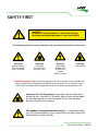
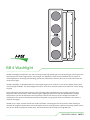
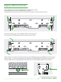
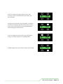
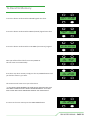
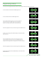
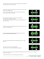
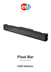
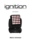
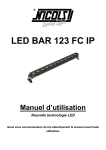
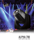
User Manual
BB4
i-PIX
BB4 washlight
BB4
contents
INTRO, RIGGING, SET UP & MODES
SAFETY FIRST
THE BB4
RIGGING
SET UP
MODES
MODES A GRAPHICAL OVERVIEW
page 3
page 5
page 6
page 9
page 12
page 15
OPERATING INSTRUCTIONS
STAND ALONE FUNCTIONS
STORING A DMX INPUT AS A MEMORY
CREATING A MEMORY
RECALLING A MEMORY
CREATING A CHASE
page 16
page 16
page 17
page 19
page 21
THE TECHNICAL STUFF
TECHNICAL SPECIFICATIONS
UNIT DIMENSIONS DRAWING
TROUBLE SHOOTING
QUICK RESET
page 23
page 25
page 26
page 28
APPENDICES
APPENDIX 1
APPENDIX 2
ROHS COMPLIANCE
AND WEEE DIRECTIVE INSTRUCTIONS
SERVICE CONTACT DETAILS
page 29
page 30
BB4 USERS MANUAL - PAGE 2
SAFETY FIRST
WARNING!
Read the safety precautions in this section before
installing, powering, operating or servicing the BB4
The following symbols are used to identify important safety information in this manual:
Warning!
Safety hazard.
Risk of severe
injury or death
Warning!
LED light
emission. Risk
of eye injury
Warning!
Hazardous
voltage. Risk
of lethal or
severe
electric shock
Warning!
Fire hazard
! Read this manual before installing, powering or servicing the fixture, follow the
safety precautions listed below and observe all warnings in this manual. If you
have questions about how to operate the fixture safely, please contact I-Pix.
Warning! Class 2M LED product. Do not look into the beam from a
distance of less than 40 cm (16 inches). Do not stare into the beam
for extended periods at a short distance. Do not view the beam
directly with optical instruments.
This product is for professional use only. It is not for household
use. This product presents risks of severe injury or death due to fire
hazards, electric shock and falls.
BB4 USERS MANUAL - PAGE 3
PROTECTION FROM ELECTRIC SHOCK
Shut down power to the entire installation at the building’s main power distribution board and lock
out power (by removing the fuse for example) before carrying out any installation or
maintenance work.
Disconnect the fixture from AC power before removing or installing any cover or part
and when not in use.
Disconnect the fixture from AC power before removing or changing the fuse.
Always ground (earth) the fixture electrically.
Use only a source of AC power that complies with local building and electrical codes and has both
overload and ground-fault (earth-fault) protection.
Connect this fixture to AC power either using the supplied power cable or via 3- conductor cable
that is rated minimum 20 amp, hard usage. Suitable cable types include
ST, SJT, STW, SEO, SEOW and STO.
The voltage and frequency at the power outlet are the same as the voltage and frequency applied
to the power inlet. Only connect devices to the power outlet that accept this voltage & frequency.
Before using the fixture, check that all power distribution equipment and cables are in perfect
condition and rated for the current requirements of all connected devices.
Do not use the fixture if the power cable or power plug are in any way damaged, defective or wet,
or if they show signs of overheating.
PROTECTION FROM FIRE
Do not attempt to bypass thermostatic switches or fuses. Replace defective fuses with ones of
the specified type and rating only.
Provide a minimum clearance of 0.1 m (4 in.) around fans and air vents.
Do not modify the fixture
Apart from I-PIX accessories do not stick filters, masks or other materials directly onto the light.
PROTECTION FROM INJURY
Do not hang fixtures from each other. Use two OMEGA clamps per fixture or I-PIX
SINGLE or DOUBLE YOLKS when suspending.
When suspending the fixture, ensure that the structure and all hardware used can hold at least
10 times the weight of all devices suspended from them.
Use two secondary attachments (such as a safety cable) to secure each fixture.
Secondary attachments must be able to hold at least 10 times the weight of all devices
suspended from them and must be installed as described in this manual.
Check that all external covers and rigging hardware are securely fastened.
Block access below the work area and work from a stable platform whenever installing,
servicing or moving the fixture.
The LED emission presents a hazard to eyesight at a distance of 4 - 40 cm (1.6 -16 inches)
when the eye is exposed to the beam for longer than 0.25 seconds.
Do not look at LEDs from a distance of less than 40 cm (1 ft. 4 in.) without suitable
protective eye wear.
Do not look at LEDs with magnifiers or similar optical instruments that may concentrate the
light output.
BB4 USERS MANUAL - PAGE 4
BB4 washlight
i-PIX
BB 4 Washlight
The BB 4 washlight provides the user with an energy saving high power light. Four powerful light sources gives the
feel and look of a modern light fixture. LED in origin, the appearance from the four blended sources shows no
visible appearance of existing led technology yet has the performance we have all come to understand from this
novel form of light.
The BB 4 washlight, is equipped with four custom Light Engines from Lamina. It's one of the highest power point
source led light available. It is the homogenized source of the three saturate colours that makes our colour mixing
so good.
The performance of these light engines to i-pix's exacting colour specifications gives a tighter tolerance and
improved colour performance, which makes tungsten lighting performance from the BB 4 possible. Daylight
temperatures can also be found with ease and finally a fixture that does not need a nudge from amber to
compensate. The whites are believable and full of low power energy, which makes one wonder if the source is
really an led engine.
The BB 4 has a super smooth control with 16 bit resolution, enhancing the feel of the fixture when wishing to
emulate the tungsten performance you would expect from pre existing fixtures. Different operating modes ensure
ease of use. With consumption of 120 watts, the fixture draws half and amp on full @ 240 volts.
BB4 USERS MANUAL - PAGE 5
Rigging a BB4 horizontally
To rig a BB4 horizontally use the OMEGA brackets supplied with the lamp.
These would have your clamp of choice bolted on to them.
The OMEGA brackets can be attached to each end & the middle of the lamp using the camlocs.
First place the camloc pins in the receptacles with the levers facing out
then to secure the brackets give the levers a quarter turn clock wise.
Make absolutely sure all four attachment points are secure BEFORE rigging the light ALWAYS secure the lamp to
the truss, pipe e.t.c. with two safety bonds. One attached to the lamp through the safety point shown in fig 1
the other attached to the yolk through the safety point shown in fig 2 NEVER through or to the brackets.
fig 1
fig 2
BB4 USERS MANUAL - PAGE 6
Rigging a BB4 vertically
To rig a BB4 vertically use the SINGLE or DOUBLE YOLK hanging brackets. The brackets can be supplied as
accessories for the lamp. You would obviously have your clamp of choice bolted on to them.
The YOLK brackets can be attached to the top, middle or the lamp using the camlocs.
First place the camloc pins in the receptacles with the
levers facing out the correct way.
Then to secure the brackets turn the levers a quarter
turn clock wise.
WRONG
BB4 USERS MANUAL - PAGE 7
So after a quarter clockwise both levers should
face each other in the centre.
WRONG
ALWAYS secure the lamp to the truss, pipe e.t.c. with two safety bonds.
One attached to the lamp through the safety point shown in fig 1 the other attached to the
LAMP yolk through the safety point shown in fig 2. NEVER through or to the RIGGING yoke.
fig 1
fig 2
BB4 USERS MANUAL - PAGE 8
SET UP
1. Select appropriate dimmer curve
The BB4 offers a choice of two dimmer curves.
1 LINEAR - the output increases directly with dmx input.
2 ENHANCED - the first 10% of the output is controlled over the first 50% of the DMX input.
First press the button under the MORE legend.
4INVRT1 ADDR 001
MODE 3 5CH MORE
PRESS
PRESS
Then press the PROFILE button.
Then select the appropriate dimmer curve.
linear LIN.
PROFILE
MAN
CHASE
STORE
PRESS
CURV-LIN BACK ON
PRESS
Or enhanced ENH.
2 Disable or enable user interface backlight
Whilst in PROFILE you may choose to switch off the user
interface backlight. When you press the button above BACK
ON the legend will change to BACK OF and the backlight will
go out 5 seconds after the interface is last used, though the
backlight will come back on whenever any button is pressed.
When you press the button above BACK OF the legend will
change to BACK ON and the backlight will remain lit
constantly.
CURV-ENH BACK ON
BACK ON shows the current status
of the backlight
PRESS
CURV-LIN BACK ON
PRESS
CURV-LIN BACK OF
BB4 USERS MANUAL - PAGE 9
3 Select appropriate operating mode
The BB4 will gives you a choice of ten operating modes. These modes
will enable you to set up the lamp in the most appropriate way for the
many different jobs the lamp will be used for. The nuts and bolts of the
modes are described in detail in pages 12 to 15.
To select a mode
Keep the button below the MODE legend depressed go
through the modes, just before the one you desire stop,
then press once.
4INVRT1 ADDR 001
MODE 1 3CH MORE
PRESS
4 Select appropriate DMX address
PRESS
First press the button above the ADDR legend.
Then change the address using the 100s,10s & 1s buttons.
4INVRT1 ADDR 111
MODE 1 3CH MORE
PRESS
100s
10s
ADDR 011
1s
BB4 USERS MANUAL - PAGE 10
5 inverting the cells
Should you wish to change the running order of the cells so that instead of running.
1234
they run
4321
Press the button above 1NORM4
1NORM4 shows the current
orientation of the cells.
PRESS
1NORM4 ADDR 002
MODE 9 20CH MORE
THIS IS AN EXTREMELY USEFUL FUNCTION IF SOMEONE HAS RIGGED THE LAMP THE WRONG WAY ROUND!
To return them to
1234
PRESS
4INVRT1 ADDR 002
MODE 9 20CH MORE
press the button above 4INVRT1.
6 locking off the interface
When you are satisfied that you have set up all the lamp’s parameters to your liking it is possible to lock off
the interface so that you dont inadvertently change anything when focusing etc.
PRESS
To lock off the interface depress the MORE and ADDR
buttons simultaneously and the MORE will change to LOCK.
1NORM4 ADDR 002
MODE 9 20CH MORE
PRESS
PRESS
To unlock the interface depress the LOCK and ADDR buttons
simultaneously and the LOCK will change to MORE.
1NORM4 ADDR 002
MODE 9 20CH LOCK
PRESS
BB4 USERS MANUAL - PAGE 11
THE OPERATING MODES
The BB4 has 10 different operating modes to suit different
uses, programming styles and dmx configurations.
MODE 1 - 3 channels 8 bit
The most simple, ideal for fast programming or limited
dmx line space and as a node on a media server. All 4 cells
are treated as 1 with the 3 channels red, green & blue
affecting the whole lamp
ch1 - red all cells
ch2 - green all cells
ch3 – blue all cells
MODE 2 - 6 channels 16 bit
Ideal for fast programming or limited dmx line space and
as a node on a media server, with a greater resolution
over the colours. All 4 cells are treated as 1 with the 6
channels red, green & blue affecting the whole lamp.
Ideal for fast programming or limited dmx line
space with overall dimming & strobe control
and a greater resolution in control over the
dimming and colours.
All 4 cells are treated as 1 with the 5 channels
dim, strobe, red, green & blue affecting the
whole lamp.
ch1 - master intensity high byte all cells
ch2 - master intensity low byte all cells
ch3 – strobe all cells
ch4 – red high byte all cells
ch5 - red low byte all cells
ch6 – green high byte all cells
ch7 - green low byte all cells
ch8 – blue high byte all cells
ch9 - blue low byte all cells
MODE 5 - 12 channel 8 bit
ch1 - red high byte all cells
ch2 - red low byte all cells
ch3 - green high byte all cells
ch4 - green low byte all cells
ch5 - blue high byte all cells
ch6 - blue low byte all cells
Ideal for use with media servers where dmx
line space may be a consideration.
Each cell can be individually coloured with its
own red green blue channels. (most useful
when each cell is patched individually -3ch)
MODE 3 - 5 channels 8 bit
Ideal for fast programming or limited dmx line space with
overall dimming & strobe control.
All 4 cells are treated as 1 with the 5 channels dim, strobe,
red, green & blue affecting the whole lamp
ch1 - master intensity all cells
ch2 - strobe all cells
ch3 - red all cells
ch4 - green all cells
ch5 - blue all cells
Mode 1 - 3 ch 8 bit
MODE 4 - 9 channels 16 bit
Mode 2 - 6 ch 16 bit
ch1 - red cell 1
ch2 - green cell 1
ch3 - blue cell 1
ch4 - red cell 2
ch5 - green cell 2
ch6 - blue cell 2
ch7 - red cell 3
ch8 - green cell 3
ch9 - blue cell 3
ch10 - red cell 4
ch11 - green cell 4
ch12 - blue cell 4
Mode 3 - 5 ch 8 bit
Mode 4 - 9 ch 16 bit
Mode 5 - 12 ch 8 bit
r g
b
r g
b
r g
b
r g
b
r
R
r
R
g
G
g
G
b
B
b
B
BB4 USERS MANUAL - PAGE 12
MODE 6 - 24 channel 16 bit
MODE 8 - 27 channel 16 bit
Ideal for use with media servers, with a greater
resolution over the colours.
Each cell can be individually coloured with its own red
green blue channel. (most useful when each cell is
patched individually -6ch)
ch1 - red high byte cell 1
ch2 - red low byte cell 1
ch3 - green high byte cell 1
ch4 - green low byte cell 1
ch5 - blue high byte cell 1
ch6 - blue low byte cell 2
ch7 - red high byte cell 2
ch8 - red low byte cell 2
ch9 - green high byte cell 2
ch10 - green low byte cell 2
ch11 - blue high byte cell 2
ch12 - blue low byte cell 2
ch13 - red high byte cell 3
ch14 - red low byte cell 3
ch15 - green high byte cell 3
ch16 - green low byte cell 3
ch17 - blue high byte cell 3
ch18 - blue low byte cell 3
ch19 - red high byte cell 4
ch20 - red low byte cell 4
ch21 - green high byte cell 4
ch22 - green low byte cell 4
ch23 - blue high byte cell 4
ch24 - blue low byte cell 4
High resolution colour control over each individual
cell with a strobe and a high resolution master
intensity having overall control over all 4 cells.
ch1 - master intensity high byte all cells
ch2 - master intensity low byte all cells
ch3 - strobe all cells
ch4 - red high byte cell 1
ch5 - red low byte cell 1
ch6 - green high byte cell 1
ch7 - green low byte cell 1
ch8 - blue high byte cell 1
ch9 - blue low byte cell 1
ch10 - red high byte cell 2
ch11 - red low byte cell 2
ch12 - green high byte cell 2
ch13 - green low byte cell 2
ch14 - blue high byte cell 2
ch15 - blue low byte cell 2
ch16 - red high byte cell 3
ch17 - red low byte cell 3
ch18 - green high byte cell 3
ch19 - green low byte cell 3
ch20 - blue high byte cell 3
ch21 - blue low byte cell 3
ch22 - red high byte cell 4
ch23 - red low byte cell 4
ch24 - green high byte cell 4
ch25 - green low byte cell 4
ch26 - blue high byte cell 4
ch27 - blue low byte cell 4
MODE 7 - 14 channel 8 bit
Colour control over each individual cell with a master
intensity and strobe having overall control over all 4 cells.
ch1- master intensity all cells
ch2 - strobe all cells
ch3 - red cell 1
ch4 - green cell 1
ch5 - blue cell 1
ch6 - red cell 2
ch7 - green cell 2
ch8 - blue cell 2
ch9 - red cell 3
ch10 - green cell 3
ch11 - blue cell 3
ch12 - red cell 4
ch13 - green cell 4
ch14 - blue cell 4
Mode 6 - 24 ch 16 bit
Mode 7 - 14 ch 8 bit
Mode 8 - 27 ch 16 bit
R G
B
r g
b
r g
b
r g
b
r g
b
R G
B
R G
B
R G
B
R G
B
R G
B
R G
B
R G
B
BB4 USERS MANUAL - PAGE 13
MODE 10 36 channel 16 bit
MODE 9 20 channel 8 bit
Ideal for control over all aspects of programming
where dmx line space may be a consideration.
For each cell there is individual control over master
intensity, strobe and red green colour mixing. (most
useful when each cell is patched individually -5ch).
ch1- master intensity all cells 1
ch2 - strobe all cells 1
ch3 - red cell 1
ch4 - green cell 1
ch5 - blue cell 1
ch6- master intensity all cells 2
ch7 - strobe all cells 2
ch8 - red cell 2
ch9 - green cell 2
ch10 - blue cell 2
ch11- master intensity all cells 3
ch12 - strobe all cells 3
ch13 - red cell 3
ch14 - green cell 3
ch15 - blue cell 3
ch16- master intensity all cells 4
ch17 - strobe all cells 4
ch18 - red cell 4
ch19 - green cell 4
ch20 - blue cell 4
Mode 9 - 20 ch 8 bit
Mode 10 - 36 ch 16 bit
r g
b
r g
b
r g
b
r g
b
R G
B
R G
B
R G
B
R G
B
Ideal for control over all aspects of programming
with high resolution master intensity, high
resolution colour control and a strobe control over
each individual cell. (most useful when each cell is
patched individually - 9ch).
ch1 - master intensity high byte cell 1
ch2 – strobe cell 1 low byte cell 1
ch2 – strobe cell 1
ch4 - red high byte cell 1
ch5 - red low byte cell 1
ch6 - green high byte cell 1
ch7 - green low byte cell 1
ch8 - blue high byte cell 1
ch9 - blue low byte cell 1
ch10 - master intensity high byte cell 2
ch11 - master intensity low byte cell 2
ch12 – strobe cell 2
ch13 - red high byte cell 2
ch14 - red low byte cell 2
ch15 - green high byte cell 2
ch16 - green low byte cell 2
ch17 - blue high byte cell 2
ch18 - blue low byte cell 2
ch19 - master intensity high byte cell 3
ch20 - master intensity low byte cell 3
ch21 – strobe cell 3 cell
ch22 - red high byte cell 3
ch23 - red low byte cell 3
ch24 - green high byte cell 3
ch25 - green low byte cell 3
ch26 - blue high byte cell 3
ch27 - blue low byte cell 3
ch28 - master intensity high byte cell 4
ch29 - master intensity low byte cell 4
ch30 – strobe cell 4
ch31 - red high byte cell 4
ch32 - red low byte cell 4
ch33 - green high byte cell 4
ch34 - green low byte cell 4
ch35 - blue high byte cell 4
ch36 - blue low byte cell 4
BB4 USERS MANUAL - PAGE 14
MODES A GRAPHICAL OVERVIEW
MASTER
INTENSITY
STROBE
CHANNEL
Mode 1
Mode 2
Mode 3
Mode 4
Mode 5
3 ch 8 bit
6 ch 16 bit
5 ch 8 bit
9 ch 16 bit
12 ch 8 bit
r
R
r
R
g
G
g
G
b
B
b
B
r g
b
r g
b
r g
b
r g
b
Mode 6
Mode 7
Mode 8
Mode 9
Mode 10
24 ch 16 bit
14 ch 8 bit
27 ch 16 bit
20 ch 8 bit
36 ch 16 bit
R G
B
r g
b
r g
b
r g
b
r g
b
R G
B
r g
b
r g
b
r g
b
r g
b
R G
B
R G
B
R G
B
R G
B
R G
B
R G
B
R G
B
R G
B
R G
B
R G
B
Stand alone functions
The BB4 is able to run in a stand alone mode without any need of data from a lighting desk. The light is
capable of outputting up to 20 programmable memories and 1 chase that steps through these memories.
“The light must be in MODE 3 (5ch) for all the stand alone functions to work.”
Storing a DMX Input as a Memory
However if you have access to a lighting desk a quick and easy way to create multiple or complex
memories is to give the light the desired colour information using a lighting desk or similar DMX
generating device and use the STORE function.
1 Connect the light to the desk in the usual way making sure the address is correct and the lamp is in MODE 3.
2 Create the desired colour on the lighting desk.
3 Press the button underneath the MORE legend once.
4INURT1 ADDR 001
MODE 3 5CH MORE
PRESS
4 Press the button underneath the STORE legend once.
PROFILE
MAN
CHASE
STORE
PRESS
PRESS
5 You should then assign this memory a number using the
UP, DOWN buttons.
6 When you are happy this memory has been numbered
correctly press the STORE button wait 3 seconds and the
display will return to the main menu.
UP
DOWN
MEN 04
STORE
UP
DOWN
MEN 04
STORE
PRESS
BB4 USERS MANUAL - PAGE 16
Creating a memory
1 press the button underneath the MORE legend once.
4INURT1 ADDR 001
MODE 3 5CH MORE
PRESS
2 press the button underneath the MAN (manual)
legend once.
PROFILE
MAN
CHASE
STORE
PRESS
3 press the button underneath the PROG MEM
(program memory) legend once.
USE MEM PROG MEM
PRESS
You are now presented with the first variable of your
memory which is the Master Intensity (MINT).
The default value for the MINT is 100% - intensity full.
If you wish to alter this value use the buttons above and
below the UP & DOWN legends until you have the
desired % value.
UP MINT 100%
DOWN
UP MINT 080%
DOWN
PRESS
PRESS
4 When happy with the MINT value press the button
above MINT once.
UP MINT 080%
DOWN
Next you are presented with STRB (strobe) the second
variable of your memory which has a default value of
0% - no strobe.
UP
DOWN
STRB 080%
In the same way if you wish to alter this value use the
UP & DOWN buttons to give you the desired % value.
BB4 USERS MANUAL - PAGE 17
PRESS
5 When happy with the STRB value press the button above STRB once.
UP
DOWN
STRB
Now you are presented with the first colour RED (default 0%).
UP
DOWN
RED
000%
In the same way if you wish to alter this value use the UP, DOWN
buttons to give you the desired %. If you require 100% press the
DOWN button.
UP
DOWN
RED
100%
000%
PRESS
PRESS
6 When happy with the RED value press the button above RED once.
UP
DOWN
RED
100%
Next you are presented with the second colour GREEN (default 0%)
In the same way if you wish to alter this value use the UP, DOWN buttons to give you the desired %
If you require 100% press the DOWN button.
PRESS
7 When happy with the GREEN value press the button above
GREEN once.
UP
DOWN
GREEN000%
Finally you are presented with the third colour BLUE (default 0%).
In the same way if you wish to alter this value use the UP, DOWN buttons to give you the desired %.
If you require 100% press the DOWN button.
PRESS
8 When happy with the BLUE value press the button above
BLUE once.
UP
DOWN
BLUE 000%
BB4 USERS MANUAL - PAGE 18
Now you are given the opportunity to store your
memory If you are satisfied with all the values you
have inputted.
If however you think you may have made a mistake or
you have just changed your mind then you can return
to the start of the memory by pressing MEM button
and repeating the above process.
If you are happy with you memory you should then
assign it a number using the UP, DOWN buttons.
9 When happy with your memory number press STORE.
UP
DOWN
MEM 01
STORE
PRESS
UP
DOWN
MEM 01
STORE
PRESS
UP
DOWN
MEM 04
STORE
UP
DOWN
MEM 04
STORE
PRESS
BB4 USERS MANUAL - PAGE 19
To Recall A Memory
1 Press the button underneath the MORE legend once then.
4INURT1 ADDR 001
MODE 3 5CH MORE
PRESS
2 Press the button underneath the MAN (manual) legend once then.
PROFILE
MAN
CHASE
STORE
PRESS
3 Press the button underneath the USE MEM (use memory) legend.
USE MEM PROG MEM
PRESS
Now you will be offered the first memory MEM 01.
This will come on automatically.
UP
DOWN
MEM 01
STORE
PRESS
4 To select any other memory simply use the UP, DOWN buttons until
you find the memory you want.
UP
MEM 01
DOWN DMX MODE
The memories will come on as you select them.
“ IF YOU WISH YOUR MEMORY TO COME ON AS SOON AS YOU GIVE
THE LAMP POWER YOU WILL NEED TO PROGRAMME IT AS A TWO
STEP CHASE WITH BOTH MEMORIES HAVING THE SAME VALUE”
To return to the main menu press the DMX MODE button
UP
MEM 02
DOWN DMX MODE
PRESS
BB4 USERS MANUAL - PAGE 20
Programming a Chase
1 Ensure you have programmed all the memories that will go to make up the steps of your chase.
2 Press the button underneath the MORE legend once..
4INURT1 ADDR 001
MODE 3 5CH MORE
PRESS
PRESS
3 Press the button above the CHASE legend once.
Now the WAIT TIME will appear this is the first variable of
the chase to be set. The WAIT TIME is the time period
between cross fades that the colour is held constant for.
PROFILE
MAN
CHASE
STORE
UP WAIT TIME
DOWN
001s
PRESS
Select the appropriate time (in seconds) using the UP, DOWN buttons.
UP WAIT TIME
DOWN
002s
PRESS
4 When you are happy with the WAIT TIME press the button above
WAIT TIME once.
Now the XFADE TIME (cross fade time) will appear this is the
second variable of the chase to be set. The XFADE TIME is the
length of time the light takes to change from one colour to another.
UP WAIT TIME
DOWN
002s
UP XFADE TIME
DOWN
002s
PRESS
Select the appropriate time (in seconds) using the UP, DOWN buttons.
UP XFADE TIME
DOWN
003s
PRESS
5 Once you are happy with the XFADE TIME press the button above
XFADE TIME once.
UP XFADE TIME
DOWN
003s
BB4 USERS MANUAL - PAGE 21
Now CHASE STRT (chase start) will appear along with the option MEM 1.
This will be the first step of your chase.
Choose which memory you would like to be the first step of your chase
using the UP, DOWN buttons.
6 Once you are happy with the memory that will be your first step
press the button above CHASE STRT.
Now CHASE END will appear along with the option MEM 1.
This will be the last step of your chase.
The chase will run through all the memories numbered between the
first and last step.
PRESS
UP CHASE STRT
DOWN MEM 01
UP CHASE END
DOWN MEM 01
PRESS
Choose which memory you would like to be the last step of your chase
using the UP, DOWN buttons.
UP CHASE END
DOWN MEM 02
PRESS
7 Once you are happy with the memory that will be your last step
press the button above CHASE END once.
Now you will be offered the option USE CHASE, if you wish to simply
press yes.
The Interface will now say CHASE RUNNING.
When you wish to end or change the chase press MENU.
UP CHASE END
DOWN MEM 03
USE CHASE
YES
NO
PRESS
CHASE RUNNING
MENU
PRESS
If you leave a chase running when the light is powered down the chase will resume as soon as the light is
powered back up again.
! If the chase does not run try rerecording the first step again
BB4 USERS MANUAL - PAGE 22
BB 4 Washlight tech spec
Dimensions
Length
Height
Width
Weight
Yoke:
Power Box:
BB4 batten:
600 mm
301 mm on rubber feet
147 mm
13.5Kg total
3 KG
4.5Kg
6Kg
Mechanical design/ materials used
Batten
Power box
Yoke
Finish
Rigging
Style
Number of positions
Accessory holder
Conventional mounts
Aluminium shrouded finned diagonal heatsink
Aluminium with steel base
Folded and welded steel
Electro static powder coated black satin
16 ¼ turn camloc fasteners
8 rigging locations on yoke
Fitted with sprung retention flap
2 of 12mm bolt holes fitted at each yoke end
Note: unit comes with three scaffold clamp adaptors to accept 12mm bolts, equipped with
two camloc ¼ turn bolts
Electrical connections for mains and data in/out
Combined power and data connection
Input
Chassis mounted male IP67 6 pin
Output
Chassis mounted female IP67 6 pin
Fixture feed
Chassis mounted female IP67 7 pin
Fixture feed
Trailing 7 pin male
Mains and data
Input inline female
6 pin Ceep
Output
6 pin Ceep
Electrical
120 watts total power on full.
Input
Power
Fuse
Output to fixture
90- 265 Volt 50/60 Hz
0.5 amps @ 240 volts
20mm x 5mm slow blow 24 amp
15 volts max
Data type
USITT DMX512-A
Note; units comes complete with 16 amp cee form plug and 5 pin xlr male. A 1
metre combined power cable link is also supplied.
Control RGB additive colour mixing
DMX channels
User interface
3 channels minimum 36 channels maximum
weatherproof backlit lcd display with
four membrane switches
BB4 USERS MANUAL - PAGE 23
Modes
8 bit
1
3
5
7
9
standard resolution
1 x RGB over 4 cells
1 x RGB over 4 cells with an overall master and strobe
4 x RGB
4 x RGB with an overall master and strobe
4 x RGB each with individual master and strobe
16 bit
2
4
6
8
10
high resolution (recommended)
1 x RGB over 4 cells
1 x RGB over 4 cells with an overall master and strobe
4 x RGB
4 x RGB with an overall master and strobe
4 x RGB each with individual master and strobe
note 16 bit for every channel bar strobe which runs as 8 bit
Note; please refer to power box or user instructions or website for channel allocation details. Most
popular lighting desks have personalities available for download from their respective websites or the
downloads section on our website.
Light Engine
Source
Wavelengths
Optics
Customised lamina Titan RGB LED
Red
625 Nm +/- 2.5 Nm
Green 517 Nm +/- 2.5 Nm
Blue 452.5 Nm +/- 2.5 Nm
4 x evenly spaced 20 degree optic
note: further photometric data and IES files are available for download from our website
Thermal characteristics
Fixture front
Power box
Passive convection cooled
Force air cooled via low airflow/ low noise fans, mounted to the base
Operating temperature
Minimum
Maximum
Weather protection
Fixture front
Power box
Humidity max
-20 degrees C
+ 46 degrees C
Hermetically sealed to IP67
Mounted horizontally facing upwards
Rated to IP65H
20% ~ 90% RH non-condensing
Approvals & Compliance
BS EN 55103-1 Harmonics
BS EN 55103-2 Immunity
USA / Canada ETL pending
Lead and mercury free return to manufacturer for recycling
IP Protection
BS EN 61000-3-2 Emissions
Patents filed in USA
Manufactured in the United Kingdom by
We reserve the right to improve this fixtures design.
BB4 USERS MANUAL - PAGE 24
BB4 USERS MANUAL - PAGE 25
TROUBLE SHOOTING
DISCLAIMER: Please note that the information contained in this trouble-shooting guide is generalized in nature & cannot
account for all possibilities. Any proposed remedies for specific situations should not be considered as absolute or all
encompassing. Please seek professional assistance if there is any doubt as to the efficacy of a remedy or of the exact nature of
any encountered problem. I-pix provides the information contained herein only as a guide.
No response from the light
Does the LCD
screen light up
No
Yes
Does the unit have
a good power supply
Yes
Is the LCD
screen flashing
Check the fuse
is it blown
No
Yes
Yes
There is no signal
check DMX input
Contact I-Pix for more specific help with
your problem, as it could be an
internal fault.
If you have the technical knowledge &
skills you could open up the unit & Yes
check for loose connections
Replace with the
appropriate fuse 4A
Mains supply keeps tripping out blowing fuses:
Does the mains
supply trip before
the light/s are
given power?
Yes
No
Contact I-Pix for more specific help with
your problem, as it could be an
internal fault.
If you have the technical knowledge &
skills you could open up the unit & check
for loose connections shorts & faults
Does the mains
supply trip when
the light/s are
given power?
Yes
No
Check all external
wiring for faults or
the supply overloaded.
If problem persists
contact a competent
electrician.
Is the mains supply
overloaded with the
addition of the
lamp?
Yes
Remove some of the
load from the supply
upgrade the supply
rating - split the load
across more circuits
No
When you try the
lamp on a different
supply does it work
Yes
Contact a competent
electrician to
check out the supply
that
could be faulty
BB4 USERS MANUAL - PAGE 26
TROUBLE SHOOTING
The fuse on a unit repeatedly blows
•
•
•
Are you fitting right rating/type of fuse into unit?
Contact I-pix for more specific help with your problem, there may be an internal fault in the unit.
If you have the technical knowledge/skills you could look inside the unit and check the internal wiring for a lose
connections/shorts and also the power supply is working with a 15v output when
there is no load connected to it.
Dmx trouble shooting
The obvious
•
It is good practice to connect data line and terminate before switching on device.
•
Is the dmx line fitted to a buffer and data is being received
•
Is the dmx data line fitted with a line termination?
•
Does the unit’s dmx mode set-up match the personality/ profile for the console provided?
•
Note: the LCD screen flashes intermittently when no data is present
BB4 USERS MANUAL - PAGE 27
QUICK RESET
An easy way of returning the light to its default settings.
PRESS
Before the light is given any power hold down both
both buttons on the left hand side of the interface.
PRESS
Keep the buttons held down as you give the light power.
When you see screen with the black boxes let go of
the buttons and the next screen will appear. If you
do not let go it will stay locked until you let go.
PRESS
PRESS
Then the light will return to MODE 10 ADDR 001
4INVRT1 ADDR 001
MODE10 36CH MORE
This is a fast way of readdressing a light, that will save you a few button presses
BB4 USERS MANUAL - PAGE 28
RoHS AND WARRANTIES
I-PIX BB4s COMPLY WITH RoHS RESTRICTIONS
I-PIX BB4s are compliant with all of the criteria proposed by the European
RoHS directive 2002/95/EC for hazardous material content in electronic and
electrical equipment as listed in Annex 1A and 1B of the WEEE Directive.
In addition to containing no mercury, the LED light engines have the
following environmental advantages over traditional light sources:
!
High energy efficiency
!
Long lifetime
!
Fully dim-able
!
Very low IR and UV radiation
For attachment of electrical connections I-Pix use lead free solder
R
C
US
RoHS
2002/95/EC
COMPLIANT
WARRANTY STATEMENT
I-Pix (seller) extends warranty on all the electronics in the BB4 produced by
the Seller for two (2) years from original date of shipment, that the goods
sold hereunder are new and free from substantive defects in workmanship
and materials. This warranty extends only to the Buyer and not to indirect
purchasers or users . Sellers liability under the foregoing warranty is limited
to replacement of goods or repair of defects or refund of the purchase price
at the Sellers sole option. The above warranty does not apply to defects
resulting from the improper or inadequate maintenance, unauthorized
modification, improper use or operation outside of Sellers specifications for
the product, abuse, neglect, or accident. THE ABOVE WARRANTY IS
EXCLUSIVE AND NO OTHER WARRANTY, WHETHER WRITTEN OR ORAL, IS
EXPRESSED OR IMPLIED. I-PIX SPECIFICALLY DISCLAIMS THE IMPLIED
WARRANTIES OF MERCHANTABILITY AND FITNESS FOR A PARTICULAR
PURPOSE - I-PIX Jan 01, 2009
WEEE
COMPLIANT
WARRANTY STATEMENT
I-Pix (seller) extends warranty on all the L.E.Ds in the BB4 produced by the
Seller for one (1) year from original date of shipment, that the goods sold
hereunder are new and free from substantive defects in workmanship and
materials. This warranty extends only to the Buyer and not to indirect
purchasers or users. Sellers liability under the foregoing warranty is limited
to replacement of goods or repair of defects or refund of the purchase price
at the Sellers sole option. The above warranty does not apply to defects
resulting from the improper or inadequate maintenance, unauthorized
modification, improper use or operation outside of Sellers specifications for
the product, abuse, neglect or accident. THE ABOVE WARRANTY IS
EXCLUSIVE AND NO OTHER WARRANTY, WHETHER WRITTEN OR ORAL, IS
EXPRESSED OR IMPLIED. I-PIX SPECIFICALLY DISCLAIMS THE IMPLIED
WARRANTIES OF MERCHANTABILITY AND FITNESS FOR A PARTICULAR
PURPOSE - I-PIX Jan 01, 2009
BB4 USERS MANUAL - PAGE 29
SERVICE CONTACT DETAILS
Broadstone Mill
Broadstone Road
Houldsworth Village
Cheshire
SK5 7DL
[Located 4 miles from Manchester airport and the city centre]
Tel: 44 (0)161 443 4140
E-mail: [email protected]
www.i-pix.com
BB4 USERS MANUAL - PAGE 30