1
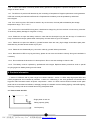
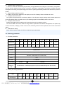
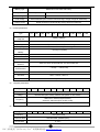
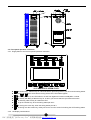
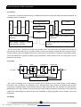
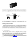
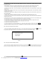
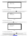
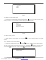
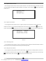
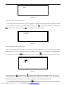
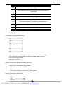
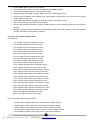
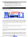
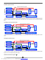
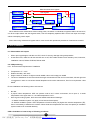
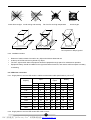
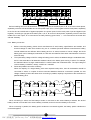
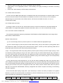
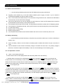
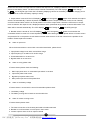
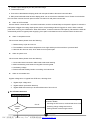
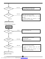
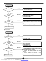
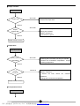
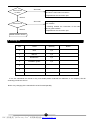
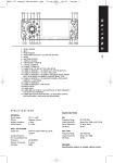
L series 1/1 online UPS (1KVA~20KVA)
User ’s Manual
1
PDF 文件使用 "pdfFactory Pro" 试用版本创建 www.fineprint.cn
Table of contents
1. Importance indication ----------------------------------------------------------------------------------------------------------------------3
1.1. Applied condition------------------ ----------------------------------------------------------------------------------------------------3
1.2. Working entironment-- ------------ ---------------------------------------------------------- ----------------------------------------3
1.3. Safety notice------------------------- ---------------------------------------------------------------------------------------------------3
2. Product information-------------------------------------------------------------------------------------------------------------------------4
2.1. How to name the UPS------------- ---------------------------------------------------------------------------------------------------4
2.2. Main features----------------------------------------------------------------------------------------------------------------------------5
2.3. Technology parameters---------------------------------------------------------------------------------------------------------------6
3. UPS appearance introduction------------------------------------------------------------------------------------------------------------8
3.1. 1~3KVA UPS---------------------------------------------------------------------------------------------------------------------------8
3.2. 4~20KVA UPS, 6~20KVA UPS--------- -----------------------------------------------------------------------------------------8
3.3. Front panel operation instruction---------------------------------------------------------------------------------------------------9
4. Brief introduction of UPS configuration-----------------------------------------------------------------------------------------------11
4.1. Rectifier---------------------------------------------------------------------------------------------------------------------------------11
4.2. Inverter----------------------------------------------------------------------------------------------------------------------------------11
4.3. Battery-----------------------------------------------------------------------------------------------------------------------------------12
4.4. Switch-----------------------------------------------------------------------------------------------------------------------------------12
4.5. Dispalying and touching screen operation--------------------------------------------------------------------------------------12
4.6. L series 1/1 large screen LCD display and operation------------------------------------------------------------------------13
4.7. RS232 intelligent communication-------------------------------------------------------------------------------------------------23
4.8. RS485 intelligent communication-------------------------------------------------------------------------------------------------24
4.9. Communication of SNMP and distant web-------------------------------------------------------------------------------------24
4.10. Dry connect state communication----------------------------------------------------------------------------------------------25
5. UPS Working principle -------------------------------------------------------------------------------------------------------------------26
5.1. Working principle of complete machine ----------------------------------------------------------------------------------------26
5.2. Mains operational mode ------------------------------------------------------------------------------------------------------------28
5.3. Battery inverter operational mode -----------------------------------------------------------------------------------------------28
5.4. Bypass operational mode ----------------------------------------------------------------------------------------------------------28
5.5. Manual maintenance bypass mode ---------------------------------------------------------------------------------------------28
6. UPS installation ----------------------------------------------------------------------------------------------------------------------------29
6.1. Disassemble and inspect ----------------------------------------------------------------------------------------------------------29
6.2. UPS positioning ----------------------------------------------------------------------------------------------------------------------30
6.3. UPS wires connection --------------------------------------------------------------------------------------------------------------30
6.4. Connection inspection-------------------------------------------------------------------------------------------------------------33
7. Operation and management ------------------------------------------------------------------------------------------------------------33
7.1. Preparations before turning on the machine ----------------------------------------------------------------------------------33
7.2. The first time turn on the UPS-----------------------------------------------------------------------------------------------------34
7.3. Test in AC mode operation------------------------------------------------------ ---------------------------------------------------34
7.4. Test in battery mode operation -----------------------------------------------------------------------------------------------34
7.5. Daily operation management -----------------------------------------------------------------------------------------------------34
8. Daily maintaining --------------------------------------------------------------------------------------------------------------------------35
8.1. Defance maintenance --------------------------------------------------------------------------------------------------------------35
8.2. Battery maintaining ------------------------------------------------------------------------------------------------------------------35
8.3. The explanation of alarm----- ------------------------------------------------------------------------------------------------------35
9. Packing list ----------------------------------------------------------------------------------------------------------------------------------42
2
PDF 文件使用 "pdfFactory Pro" 试用版本创建 www.fineprint.cn
1. Importance indication
This manual contains the guidance of UPS and accumulator when installation and application, also includes the
guidance of problem setting and maintenance.
Ø
Please read this user manual carefully before using or installing the machine.
Ø
This manual must be read to and conserved by a professional person.
Ø
This manual does not introduce the specified technologies.
Ø
This manual applies to the L series 1/1 online UPS.
This manual provides the reference when using and guidance when alarming and working.
1.1. Applied condition
This UPS provides AC power supply, which is the basic power of your equipment. Please carefully check whether
the input and output pressure and frequency can meet the using requirements.
UPS input AC capacitor must be as requested. Otherwise the UPS will work improperly or even occur security
accident (when the UPS input is generator, generator capacity should be 3 multiple more than UPS).
1.2. Working environment
The working environment and maintain methods also influent the using age and failure rate of the UPS. Therefore,
please avoid the following working environment in long term.
Places over demand of specifications (temperature 0℃~40℃, relative humidity 30%~95%).
Places with bare sunshine.
Places near by the heat sources. Over heat will speed up the external battery self-discharge.
Places liable to shaking and shoving.
Places have powder, corrosive substances and combustible gas.
1.3. Safety notice
1.3.1. Generally the UPS is in connection with batteries. So that there might still be voltage in the output end even
without AC input.
1.3.2. When UPS need to be moved or re-wiring, you must ensure that all UPS stop working, electricity input and
batteries input is off. Otherwise, there may still be risk of electric shock in the output end.
1.3.3. To ensure the person’s safety, this series UPS must be of good grounding protection and of reliable grounding
before the using.
1.3.4. Please keep the air intake and exhaust open. Poor ventilation will increase the internal temperature of the UPS
and therefore short the lifetime of UPS spare parts.
1.3.5. Liquid and other objects should not be leaked into the inside UPS inside box.
3
PDF 文件使用 "pdfFactory Pro" 试用版本创建 www.fineprint.cn
1.3.6. In case of fire broken out around, please use dry powder fire extinguisher. Liquid fire extinguisher will be
danger of electric shock.
1.3.7. The life time of product will decrease by the increasing of temperature. Regular replacement could guarantee
UPS work normally and maintain sufficient time. Replacement the battery must be operated by authorized
technologists.
1.3.8. If no use it long time, UPS must be stored in dry environment, the host (without batteries) the storage
temperature range: -40 ℃~+70 ℃.
1.3.9. In term of no use the UPS for long time, it is advised to charge it by AV for more than 12 hours every 3 months.
To avoid any battery damage for long time no using.
1.3.10. Please do not open the battery cabinet in case that the electrolyte injury the skin and eye. If incaution the
body contact the electrolyte, please wash it with plenty of water and then go to the hospital.
1.3.11. Please do not open the cabinet by yourself because there are many high voltage accumulator spare parts.
Otherwise any accident arisen should at your peril.
1.3.12. Please do not disassembly any connection cable by yourself without permission.
1.3.13. Because this UPS is very big and heavy, please do not move and shake it violently. Also good ventilation is
necessary.
1.3.14. Do not exhaust the dust when it is electrophorus. Do not use wet washrag to clean the dirt.
1.3.15. The battery must be replaced by professional technologist. Replaced battery should be send to special
recycling agencies. Battery belongs to toxic waste.
2. Products information
L series 1/1 UPSs are with a power range from 1KVA to 20KVA. L series 1/1 UPSs adopt high-speed MCU and
CPLD programmed and controlled by software. L series 1/1 UPSs bring in the sixth generation low-exhaust and
big-power IGBT and static switch as power components. L series 1/1 UPSs combine world’s newest control spare
parts and the most advanced software, and apply broadly to industrials such as building lighting, road traffic lighting,
electricity, industry and other industrial and mining enterprises fields.
2.1. How to name the UPS
L
xxx ----------------- 1/1
Single phase in and out
Rating capacity (KVA)
Low frequency
4
PDF 文件使用 "pdfFactory Pro" 试用版本创建 www.fineprint.cn
UNINTERRUPTIBLE POWER SUPPLY
Nam e: UPS
Type:
L**K
I nput v ol tage:
220VAC± 20% , 5 0Hz
O ut put v ol tage: 220VAC±2% , 50 Hz
Bat t ery v ol tage: 192VDC
Product i on dat e:
Product i on num ber: PCUPST T 400K0 605 080 0 1
PC1215400K9H060508
Name——UPS;
Type——it means the UPS’s rating capacity; please refer to the product naming regulation.
Input pressure——rating input pressure and frequency
Output pressure——rating output pressure and frequency
Battery pressure——rating battery pressure
Production date——leave factory date
Production number——production serial number
Code number——CODE-39 standard
2.2. Main features
l
Online working pattern and prompt static switch
l
Intelligent digital control technology
It adopts 3 high-speed microprocessor controlling system and operation parameters which make its operation &
management more perfect and its self-diagnosis and self-detect function stronger. You can also fully trust the sine
wave which was converted by figure voltage to operate perfectly and meet your demand.
l
Efficient IGBT inverter AB technology
l
High-speed switch feature of IGBT; high voltage and large current; adopt voltage drives, only needs little control
power. With lower saturation voltage of the fifth IGBT, the inverter AB works more efficiency and reliable.
l
Superior load
It is completely capable to load from 0-100% while no need to change to bypass, which make sure the output
reliable.
l
Intuitive view of the LED working state and work flow
l
Humanized big touch screen LCD in both Chinese and English
It provides intuitive view of intelligent icon status of the flow chat, tabular data, events records and menu operation
in both Chinese and English.
l
Perfect protection
It has output over/low load protection, input surge protection, phase sequence protection; battery over
charge/discharge protection; short circuit protection; over-temperature protection and so on, as well as alarming
function.
l
High dynamic performance
Adopting kinds of feedback control such as instantaneous control method and valid date, it achieves high dynamic
adjustment and reduces the output THD.
l
Adopt 6 pulse rectifier (option 12 pulse and input harmonic filter)
Effectively restrain the input THD; raise UPS input power factor, reduce the input THD current.
5
PDF 文件使用 "pdfFactory Pro" 试用版本创建 www.fineprint.cn
l
Intelligent battery management
L series 1/1 UPSs can automatically adjust battery charge parameters according the user’s battery configuration,
and can achieve battery float and boost conversion, temperature compensation and battery charge& discharge
management according to the power supply environment. It prolongs the battery’s lifetime and reduces the operator’s
burden.
l
Optional battery detecting module
It is able to test the single parameter, and display on the LCD. If battery failure it will alarm to runner.
l
Intelligent detection function
The system microprocessor will continuously detect on line all power’s supply working status, breaker status, and
all circuits working status. Any failure occurs, the detecting system will immediately alarm to the runner.
l
Intelligent communication
RS232 and RS485 interface realizes multi-communication and long distance monitor.
The choice SNMP card 100% carries out long distance supervision and network management; the optional dry
contact connection, adopting no have no the source, efficiently carries out the supervision and control of the UPS
status.
l
Characteristic setting
As per different power supply, the UPS can adjust the input parameters.
2.3. Technology parameters
(1)Rectifier parameters
Type
L1K
L2K
L3K
L4K
L6K
L8K
L10K
L15K
L20K
L30K
Range(KVA)
1
2
3
4
6
8
10
15
20
30
6
12
18
24
35
45
57
86
114
172
Input
capacity(A)
Working
Pure sine wave
Phase
1 phase+N+G
Voltage
220VAC±25%(UPS mode), 220VAC±10%(ECO or UPS mode)
50Hz±10%, 60Hz±10%(UPS mode)
Frequency
50Hz±5%, 60Hz±5%(ECO or UPS mode)
THDi
<5%
Soft start
0~100% 5s
Output voltage
55 VDC
220VDC
Set the DC
voltage by
42-60VDC/200~232VDC(change them by the professional engineer with the soft)
soft
(2)Battery and charge parameters
Type
Max current
discharge(A)
L1K
L2K
L3K
L4K
L6K
L8K
L10K
L15K
L20K
L30K
24
48
71
24
36
48
60
90
120
179
6
PDF 文件使用 "pdfFactory Pro" 试用版本创建 www.fineprint.cn
Battery type
Maintenance-free lead acid battery
Battery numbers
4pcs
16pcs
DC voltage
48VDC
192VDC
Float voltage
55VDC/220VDC(once of three months charge, charge votage 56.8/232VDC)
Charge power
Rated powerX20%(automatically change follow the batteries)
(3)Inverter parameters
Type
L1K
L2K
L3K
L4K
L6K
Rated power
L8K
L10K
L15K
L20K
L30K
Capacity ×0.8(KW)
Cosφ=0.8
Phase
Single phase(L+N+G)
Voltage
220±1%(state load, 220±5%(fluctuate load))
Frequency
50Hz±0.5%, 60Hz±0.5%(with battery)
Output frequency
<±0.5%(no in phase)
stability
Input frequency
50Hz±5%
Crest factor
3:1
Wave
Pure sine wave
Output waveform
Pure sine wave, linear load<3%; non-linear load<5%
distortion
Dynamic
<±5%(0←→100% load)
characteristics
Recover time
<10ms
Overload
125% 1 minute, 150% 1s
Inverter efficiency
≥95% (load 100%)
(4) Baypass parameters
Type
L1K
L2K
L3K
L4K
L6K
L8K
L10K
L15K
L20K
Phase
Single phase
Voltage
220VAC±25%(UPS mode), 220VAC±10%(ECO or UPS mode)
L30K
50Hz±10%, 60Hz±10%(UPS mode)
Frequency
50Hz±5%, 60Hz±5%(ECO orUPS mode)
Transfer time
<1ms (inverter←→bypass)
(5)Systerm parameters
Type
L1K
L2K
L3K
L4K
L6K
L8K
L10K
Efficiency
>80%(100% load)
Communication
RS232/RS485, (SNMP option)
Temperature
0~40℃
7
PDF 文件使用 "pdfFactory Pro" 试用版本创建 www.fineprint.cn
L15K
L20K
L30K
Relative
humidit(no
30%~90%
coagulation)
<1000M(a 1% decrease against 100 meters’ rise; altitude 4000M Max)
Height(Max)
Cooling down
Compulsive ventilation(with temperature control)
method
Noise dB
40~50
50~55
55~60
Cabinet colors
Grey(option other colours)
Input place
Under/back
Easy to
Top/left or right side open
maintain
Cabinet size
W×D×H(mm3)
Weight(Kg)
210×495×500
38
45
210×580×540
60
105
138
380×680×900
155
185
Input mode
With the line connection
Output mode
With the line connection
430×750×1050
215
All the above parameters are reference only, any difference please refer to the actual UPS.
3. UPS appearance introduaction
3.1. 1~3KVA UPS
LED display
RS232 port
cooling fan
RS485 port
LCD display
SNMP card
control switch
switch mark
power swtich
cooling holes
connections
wheel
3.2. 4~20KVA UPS, 6~20KVA UPS
8
PDF 文件使用 "pdfFactory Pro" 试用版本创建 www.fineprint.cn
245
318
LCD
3.3. Front panel operation instruction
3.3.1. Single phase in and out front panel operation instruction
旁路 输入
l
旁 路运 行
主电 输入
整流 正常
温度 故障
工作 指示
电 池正 常
逆 变正 常
输出 指示
电池 低压
输出 过载
is function key,take the key for 5 seconds as the ups turning off then you can enter the seting status.
l Take the
+
at the same time is turning off the UPS, UPS will be bypass.
l
is ON key, take it for 2s, UPS will turn on and from bypass to inverter normallyafter 1 minute.
l
is ON key with BAT, pls take the key for 1s when you want to start the ups without the mains.
l
is reset key, take the key for restart the UPS.
l
is up the number key, when the seting status pls use it.
l
is moving the cursor key, when the seting status pls use it
l
is turning over the screen key, mainly use to turn over the screen for looking the UPS working status.
3.3.2. Led display introducations
9
PDF 文件使用 "pdfFactory Pro" 试用版本创建 www.fineprint.cn
A.
B.
C.
Working status lamp -- indicate each part of the circuit working status when it works.
Ø
Bypass input -- lightens when bypass input power’s voltage and frequency are within normal range.
Ø
Bypass operation -- lightens when static switch is bypass working status.
Ø
Main power input -- lightens when main input power’s voltage and frequency are within normal range.
Ø
Rectifier normal -- lightens when rectifier works normally.
Ø
Inverter normal -- lightens when inverter works normally.
Ø
Input indication -- lightens when UPS inputs.
Ø
Wrong phase order -- lighten when input AC’s phase order has error.
Ø
Working status -- lightens when controlling circuit of the whole machine works normally.
Ø
Battery normal -- lightens when battery’s voltage works normally.
Ø
Low voltage -- lightens when the voltage of the battery is low.
Ø
Overloaded input -- lightens when the input is overloaded.
Screen plus LCD
Ø
Touch screen -- you can touch directly on the screen board and enter into the corresponding menu.
Ø
LCD -- show the status and figures.
Detailes please refer to the part of display and communication.
Ø
Rectifier switch -- the breaker controls the rectifier’s input. Meanwhile it protect the rectifier: the breaker cuts
when the rectifier is over current。
Ø
Bypass switch -- the breaker controls the bypass’s input and protect the bypass meanwhile. The breaker
cuts when bypass circuit is over current.
Ø
Battery’s switch -- the breaker controls the battery’s input and protects the battery group meanwhile. The
breaker cuts when battery group is over current.
Ø
Input switch -- the breaker controls the UPS’s AC output and protects the output meanwhile. The breaker
cuts when input over current or short circuit.
Ø
Maintain switch -- it is used for maintain UPS with uninterruptible power, it will turn off when working
normally. Please refer to correct flow when using this swift, otherwise it will cause the failure of UPS or
output cut.
The process of cut off the maintainence switch: turn on the bypass switch, meanwhile turn off the inverter by
manual, then turn off the output switch, the cut off the maintainence switch, and then turn off the rectifier switch and
battery switch.
D.
Connection end -- cables connect the input, output and battery.
E.
Dry connection point connections
F.
RSS232 communication meet end -- connect the RS232 meet end in the computer. It will monitor the UPS in
background through monitor software.
G.
RS485 communication meet end -- connect the RS485 meet end in the computer. It will monitor the UPS in
background through monitor software.
H.
SNMP card -- connect the Intel website and operate the web long-distance monitor.
I.
Boarding -- open it and screw and connect lines
J.
Idler wheel -- to move the UPS when installing. Should be fixed after installation.
10
PDF 文件使用 "pdfFactory Pro" 试用版本创建 www.fineprint.cn
4. Brief introduction of UPS configuration
4.1. Rectifier
Convert the 1 phase’s input AC electricity into stable DC through the rectifier and charge the battery meanwhile. Its
consisted parts are as following:
Rectifier circuit
MCU
DC bus filter
BUS FILTER
Harmonic filter
1phase mains
Rectifier switch
Inverter
6 or 12 pulse rectifier
Batteries
Input voltage and frequency
Battery voltage and charging circuit
inspection
inspecbtion
Input
voltage
frequency
default
Charging voltage and circuit controlling, BUS
phase Rectifier controlling
protection
As the above chart, controlled by input through rectifier switch, the main power was rectified to DC firstly by
harmonic filter and secondly the 6 or 12 pulse rectifier. At last it was rectified to stable DC bus by harmonic again.
Though measuring the input voltage and frequency and DC bus and controlling the rectifier, the commutating control
circuit input stable DC to inverter and battery group. Meanwhile it starts protection when I/P wrong phase, be lack
phase and over limited.
4.2. Inverter
Filter
¸Transformer
IGBT
Output filter
DC input
Load
Sampling
Sampling
Reactive circuit
Sampling
CPU
Reactive circuit
Be consist of sampling circuit, single-chip controlling circuit, IGB driving circuit, IGBT module, inverter isolating
transformer, filter inductance and protecting circuit. Microprocessor firstly produce the SPWM signal through
computing the sampling signals, and meanwhile drive the IGBT module bas AC and change it into high frequency
SPWM waves. Secondly it output pure sine AC through inverter isolating transformer, inverter filter. At the same time
it adjust the output voltage and waves’ shape via the feedback of sampling signals such as voltage, current and
temperature.
4.3. Battery
11
PDF 文件使用 "pdfFactory Pro" 试用版本创建 www.fineprint.cn
Battery is consisted of the power slot (plastic crust), the cathode plate, the negative electrode, separator,
electrolyte, inter-unit bridge, terminations, safety valves and other components. It is a power and chemical energy
conversion devices. The working principle is, when AC is normal the charger will charge and the battery will convert
the power to chemical energy which will be stored in the battery; when the AC works abnormally the battery will
convert the chemical energy to power to UPS.
4.4. Switch
Static bypass switch
Bypass switch
Output switch
Inverter
Static inverter switch
The UPS pattern is dual-mode transformation. When the inverter does not start it is bypass mode; after turning on
the inverter it will high-speedily switch from static bypass switch to static inverter output switch. As static switch is
electronic switch so there is no mechanical switching time.
4.5. Displaying and touching screen operation
4.5.1. Touching screen information
Touch-screen LCD monitors is our company’s latest invention of the UPS modules, using today's most popular and
intuitive graphical operation interface. Comparing with the traditional button-LCD display modules, the touch-screen
display module shows a more rich content which avoids frequent page turning. At the same time because the user
can get corresponding information by directly press the button on the display screen. It is easy to use easy to get.
Meanwhile touch-screen display module comes with real-time clock and memory and can be recorded 256 incidents
and other information, which is more humanize.
4.5.2. Operation and introducation
Stand by screen shown in chart 1. UPS will start up in the show this standby screen. When the touch-screen
interval of about four minutes not to touch, shows CPU will automatically cut off power ----- touch screen backlight
can be extended so the backlight life, and return to the standby interface (if UPS is in the police state, the touch
screen will be Priority information shows that the police box, police information to repeal or abolish manual alarm will
not be cut off before the show CPU touch screen backlight back to standby power supply interface).
12
PDF 文件使用 "pdfFactory Pro" 试用版本创建 www.fineprint.cn
4.6. L series 1/1 large screen LCD display and opteration
4.6.1 Standby interface
Standby interface see chart one. When turn on the UPS it will display the standby interface. When the LCD around
1 minute no one operation, the display CPU will automatically cut off the display back light….so as to enlarge the
lifetime of back light, meanwhile back to the standby interface (if the UPS in alarm statuts, the display will prior to
display the alarm information, before the alarm information withdraw or manual withdraw the alarm the display CPU
will not cut off the LCD back light and back to the standby interface).
Green
Power
Chart 1
4.6.2. Flow chart display interface
enter into flow chart
Flow chart display interface see chart 2. In standby interface press the scroll key
display interface. In this interface will see the UPS working working and operation statues display. The meaning for
each part of the interface as following
2
4
6
5
7
8
9
10
3
13
11
1
12
Chart 2
13
PDF 文件使用 "pdfFactory Pro" 试用版本创建 www.fineprint.cn
1. Subordinative unit mark: when the screen displays this mark, it shows that in parallel system this UPS in
subordinative status.
2. Thin real line: connect the no working module with thin real line shows this module already stop working.
3. Thick real line: connect the working module with thick real line shows this module in working mode.
4. Rectifier and input mark: in flow chart interface, it means rectifier module. If this mark flickers, it means input
switch cut off.
5. Battery batch and battery switch mark: in flow chart interface it means battery batch, if this mark flicker it means
the battery switch cut off.
6. Maintainence bypass switch: display the maintainence bypass switch status, if this mark flicker it means turn on
the manual bypass.
7. Bypass switch: display the bypass switch status, if this mark flicker it means bypass switch cut off.
8. Inverter and DC fuse mark: in flow chart interface it means inverter module, if at the same time this mark flicker, it
means DC fuse cut off.
9. Count down turn on mark: when the LCD display S mark, it means the system enter into turn turn off status; when
the LCD display R mark, it means the system enter into count down turn on status.
10. Output switch: display the output switch status, when this mark flicker, it means the output switch cut off.
11. Count down time: display the remaining time of count down to turn on/off.
12. System time: display real system time
13. Current working mode: if this mark displays eco, it means the system working in ECO mode; if display UPS,
it means the system working in UPS mode, if no display then it means the system working in UPS mode.
4.6.3. UPS current operation status interface
UPS current operation status display likes chart 3. In flow chart interface press the the scroll key
into operation status display interface. In this interface can see the UPS current operation status.
and enter
On-Off status abnormal;
Phase sequence failure;
Input abnormal;
Inverter output:
Chart 3
4.6.4. UPS input information display interface
When the UPS in operation status press the scroll key on the front panel
on the front panel then enter into
UPS input information display interface, see chart 4. In this interface you can see the UPS current input information.
14
PDF 文件使用 "pdfFactory Pro" 试用版本创建 www.fineprint.cn
UPS Input:
Voltage:
220V
Frequency:
50.0Hz
Chart 4
4.6.5. Inverter information display interface
In UPS input information display interface press the scroll key
on the front panel then enter into the inverter
information display interface, see chart 5. In this interface you can see the inverter mode current information.
INV status:
Voltage:
220V
Frequency: 50.0Hz
Chart 5
4.6.6 UPS output information display interface
enter into the UPS output information display interface, see
In inverter display interface press the scroll key
chart 6. In this interface you can see the UPS current output information.
UPS Output:
Voltage:
220V
Frequency: 50.0Hz
Current: 00.0A
Chart 6
4.6.7. Temperature information display interface
In UPS output information display interface press the scroll key
then enter into the temperature information
display interface, see chart 7. In this interface you can see the UPS current temperature information.
15
PDF 文件使用 "pdfFactory Pro" 试用版本创建 www.fineprint.cn
Temperature:
1: 00℃
2: 00℃
Chart 7
4.6.8. Battery information display interface
enter into the battery information display
In the temperature information display interface press the scroll key
interface, see chart 8. In this interface you can see the battery batch current information.
Battery:
Voltage: 000V
Current: 00.0A
Backup time: 00h 00m
Chart 8
4.6.9. Back to standby interface
In battery information display interface press the scroll key
interface.
on the front panel then back to the standby
4.6.10. Management setting optional interface
In the above any interface press the up key
or left key
enter into management setting optional interface,
see chart 9. In this interface the selected content reverse video, use the up key
use the left key
finish the selec. Use the scroll key
change the selectable content,
exit this interface back to the flow interface 4.6.2.
1. System management
2. System setting
16
PDF 文件使用 "pdfFactory Pro" 试用版本创建 www.fineprint.cn
Chart 9
4.6.11. Management select interface
In the management setting interface select 1. system management .Then the LCD enter into management select
interface, see chart 10. In this interface the selected content reverse video, use the up key
content, use the left key
finish the select, use the scroll key
change the select
exit back to the previous interface 4.6.10.
1. Shut down UPS
2. System information
3. System record
4. LED testing
Chart 10
When UPS in working status, the first option is: 1. turn off UPS: When UPS in turn off status the first option is 1.
start UPS.
4.6.12. Input password interface
In management select interface select 1. turn off UPS and enter into. This operation need input password. So the
LCD enter into the password interface, see chart 11. In this interface the select content reverse video, use left key
remove cursor; use up key
increase the value or finish the select; use the scroll key
back to the
previous interface 4.6.11.
Password:
0000
OK
Chart 11
When move the cursor to OK,press up key
finish input password. If the password correctness will turn
off/start, meanwhile back to the previous interface 4.6.11; if the password failure, the LCD will not alarm, and also
clear the wrong password and reposition the cursor, UPS will in execution any operation. The nominal password of
the system is: 1234.
17
PDF 文件使用 "pdfFactory Pro" 试用版本创建 www.fineprint.cn
4.6.13. System information interface
When manage the select interface choose 2. system information. The LCD will enter system information, see chart
12. In this interface will display the rated information of the system, use the scroll key
interface 4.6.12.
back to the previous
UPS capacity: 000KVA
BAT No: 00 pcs
BAT capacity: 000AH
Chart 12
4.6.14. System record interface
In the management select interface choose 3. system record then the LCD will enter into the system record
interface, see chart 13. In this interface will display all the record of the events. Use the up key
record, use the left key
read the next nine records; use the scroll key
Serier No : 001
Code :002
Time: 2007-01-01
00:00:00
read the next
back to the previous interface 4.6.11.
Description: Battery low voltage
Chart 13
4.6.15. LED testing function
In the management select interface, choose 4. LED testing and enter. Testing the LED and the beeper for 6 mS on
the front panel, during the testing period the LED light and the beeper beep.
4.6.16. Setting the select interface
In the management setting interface choose 2 system setting. The LCD enters into setting interface, see chart 14.
In this interface the selected content reverse video, use the up key
finish the select; use the scroll key
change the optional content; use the left key
back to the previous interface 4.6.10.
18
PDF 文件使用 "pdfFactory Pro" 试用版本创建 www.fineprint.cn
1. Time setting
2. Change password
3. Clean record
4. System language
Chart 14
4.6.17 Clock setting interface
In the setting interface, choose 1 time setting. The LCD enters into clock setting, see chart 15, use the up key
change the select content, use the left key
Finish select, use the scroll key
Back to the previous interface 4.6.16.
2000-00-00
00:00:00
OK
Chart 15
Use the cursor to OK.
Press the up key
finish the clock setting, input the correct time format, the LCD will update the time, also back
to the previous interface 4.6.16.; if the time format not correct, the LCD will not display but clean all the input numbers
and the cursor will reposition. LCD is inexecution any operation.
4.6.18. Change password interface
In the setting select interface 2, change password. The LCD enter into input password interface, the LCD enter into
input password interface. The detailed operations see 4.6.12.
4.6.19. Leaning record interface
In the setting select interface choose 3.cleaning record. The LCD enters into input password interface. The
detailed operations process reference to 4.6.12. After input correct password the system will clean all the records of
the events, see chart 16. And the record is beyond retrieve, so the user should be more careful. When finish the
delete, the LCD will automatically back to the management setting interface 4.6.16.
19
PDF 文件使用 "pdfFactory Pro" 试用版本创建 www.fineprint.cn
Cleaning out the record...
050%
Chart 16
4.6.20. The interface of language setting
In the setting select interface choose 4. system language. The LCD enters into language select interface, see chart
17. In this interface the select content reverse video. Use the up key
finish the select; use the scroll key
change the select content; use the left key
back to the previous interface 4.6.16.
1. Chinese
2. English
Chart 17
4.6.21. The interface of BAT code setting
When UPS in bypass mode press after 5 ms will enter into battery setting status, once the UPS enter into battery
setting status, the LCD will automatically skip to this interface, see chart 18. In this interface the selected content
reverse video. Use the let kept
removes the cursor. Use the up key
increase the value or finish the select.
Code:
0000
OK
Chart 18
When the cursor on OK, press the up key
finish input the password. If the password correct, the LCD will
automatically ship to the next previous 4.6.22. If the password is wrong, the LCD not displays, but cleans all the input
password and reposition the cursor. LCD is inexact any operation. The nominal password is: 6666.
20
PDF 文件使用 "pdfFactory Pro" 试用版本创建 www.fineprint.cn
4.6.22. The interface of BAT capacity setting
The battery capacity setting interface, see chart 19. In this interface the select content reverse video, use the left key
move the cursor, use the up key
finish the select.
BAT capacity:
000
OK
Chart 19
The user move the cursor to OK, press the up key
finish input the battery capacity. LCD will skip to the next
interface 4.6.23.
4.6.23. The interface of working mode setting
Working mode setting interface, see chart 20. In this interface the selected content reverse video, use the up key
to move the cursor, use the left key
to finish the select.
Working mode
1. UPS
2. ECO
3. UPS
Chart 20
When the user move the cursor to the needed option, press the left key
working mode.
to make sure the input setting
4.6.24. The interface of alarm
No matter what interface,once the UPS alarm, the LCD will prior to display alarm content, unless alarm withdraw
or the user eliminate the beeper. The alar m interface display, see chart 21. Use the scroll key
alarm.
21
PDF 文件使用 "pdfFactory Pro" 试用版本创建 www.fineprint.cn
to eliminate UPS
BAT voltage is low
OK
Chart 21
Code
Detail incident description
000
Blank, no record
001
Mains error
002
Battery voltage Low
003
UPS overloaded
004
Temperature error means temp high
005
Phase order error
Phase order error: wrong input phase order
006
Inverter error
007
System error
008
Bypass output incident, means the UPS switch to bypass output
009
Inverter output incident means the UPS switch to inverter output
010
Rectifier error
011
Maintaining bypass switch is turning on
012
DC fuse is off
013
Rectifier switch is cut down
014
Bypass switch is turning on
015
Output switch is turning off
016
Battery switch is cut down
020
Batter switch is turning on
021
AC returns to normal
022
Battery voltage returns to normal
023
Load returns to normal
024
UPS temperature recover normal
025
UPS phase order returns to normal
026
Maintaining bypass switch is turning off
027
AC insurance returns to normal
028
Rectifier switch turning on
029
Battery switch turning on
030
Output switch turning on
031
Transmission error
032
Transmission returns to normal
041
Turning off automatically, means the machine is automatically shut down
because of low UPS voltage or other error, and switch to bypass output
042
UPS restart
043
UPS enter battery testing status
044
Cancel buzzer alarming manually
22
PDF 文件使用 "pdfFactory Pro" 试用版本创建 www.fineprint.cn
045
Turn off UPS manually
User sends distant count down UPS turning off command from the
051
monitor end
User sends distant count down UPS turning on command from the
052
monitor end
053
Count down time till turning off the UPS
054
Count down time till turning on the UPS
User sends distant count down UPS turning on canceling command from
055
the monitor end
056
Send battery testing command from the display panel
057
Send alarming canceling command from the display panel
058
Send turning on command from the display panel
059
Send turning off command from the display panel
061
Rectifier re-works
062
Rectifier stops working
other
Unknown error or wrong error record
4.7. RS232 intelligent communication
End definition adopts DB9 standard port
NC-------------------------------1
RXD-----------------------------2
TXD-----------------------------3
NC-------------------------------4
Signal GND-------------------5
NC-------------------------------6
NC-------------------------------7
NC-------------------------------8
NC-------------------------------9
2 pin: receiving end, receive computer RS-232 communication data in the UPS.
3 pin: sending end, send computer RS-232 communication data in the UPS.
5 pin: communication “GND”;
Other pins: no connect.
RS-232 communication provides the following functions
Monitor UPS current power supplying status.
Monitor UPS current alarming status.
Monitor UPS current running parameters.
To control the UPS time turning on/ff and set the system.
RS-232 communication data format
Baud rate ---------------------- 2400bps
Byte
-------------------------- 8bit
Over No ------------------------ 1bit
23
PDF 文件使用 "pdfFactory Pro" 试用版本创建 www.fineprint.cn
Parity check -------------------- NO
Connection of computer RS-232 and UPS RS232
Computer ----------------------------------------------------------
UPS
RXD (2 pin) --------------------------------------------------------
TX (3 pin)
TXD (3 pin) ----------------------------------------------- ----------
RX (2 pin)
GND (5 pin) --------------------------------------------------------
GND (5 pin)
4.8. RS485 intelligent communication
Port definition (from left to right)
1 pin: RS-485 communication port A(DATA+) port;
2 pin: RS-485 communication port B(DATA-) port;
3 pin: RS-485 Communication GND
4 pin: RS-485 communication port A(DATA+) port
5 pin: RS-485 communication port B(DATA-) port
6 pin: communication GND;
RS-485 communication method provides the same function with RS-232
RS-485 communication data format provides the same function with RS-232
How to connect UPS with RS-485
How to connect ------------------------------------------------- UPS
DATA+ port ----------------------------------------------------- A port(1 pin)
DATA- port ----------------------------------------------------- B port(2 pin)
GND port -------------------------------------------------------- Communication source(3 pin)
How to connect UPS with UPS RS485
How to connect -------------------------------------------------- UPS
DATA+ port ------------------------------------------------------- A port (1 pin)
DATA- port -------------------------------------------------------- B port (2 pin)
GND por t --------------------------------------------------------- Communication source (3 pin)
4.9. Communication of SNMP and distant web
Port definition
T568A standard and T568B standard
Ø
T568A standard description order from left to right is: 1-white & green, 2-green, 3-white&orange, 4-blue,
5-white&blue, 6-orange, 7-white&brown, 8-brown
Ø
T568B standard description order from left to right is: 1-white and brown, 2-orange, 3-white&green, 4-blue,
5-white&blue, 6-green, 7-white&brown, 8-brown
SNMP card has the following function
24
PDF 文件使用 "pdfFactory Pro" 试用版本创建 www.fineprint.cn
Ø
Provide SNMP MIB to monitor the UPS status.
Ø
Automatically detect and transform the 10/100M fast ETHERNET SPEED
Ø
Set the functions through internet, web browser or NMS
Ø
Support TCP/IP, UDP, SNMP, TELNET, SNTP, PPP, HTTP, SMTP agreements.
Ø
Provide facility installation and updating tools which applied to MS-windows. No need the time-costing
RS232 traditional way to set.
Ø
Send SNMP TRAP, EMAIL and pager to inform the operator when battery errors.
Ø
Can be set of sending daily history record via email.
Ø
Able to match shutdown software to protect computer system to save documents safely and turning off the
machine.
Ø
Net Agent-3 ports generation: able to link out NETFEELER LITE environment detecting system and external
modems. Also able to use the dial-up methods
4.10. Dry connect state communication
Port definition
1 pin: Rectifier signal is the COM port of relay
2 pin: Rectifier signal is the NC port of relay
3 pin: Bypass signal is the COM port of relay
4 pin: Rectifier signal is the NC port of relay
5 pin: Inverter signal is the COM port of relay
6 pin: Inverter signal is the NC port of relay
7 pin: DC input signal is the COM port of relay
8 pin: DC input signal is the NC port of relay
9 pin: BAT low signal is the COM port of relay
10 pin: BAT low signal is the NC port of relay
11 pin: System fault signal is the COM port of relay
12 pin: System fault signal is the NC port of relay
13 pin: Rectifier switch signal is the COM port of relay
14 pin: Rectifier switch signal is the NC port of relay
15 pin: Bypass switch signal is the COM port of relay
16 pin: Rectifier switch signal is the NC port of relay
17 pin: Inverter switch signal is the COM port of relay
18 pin: Inverter switch signal is the NC port of relay
19 pin: DC input switch signal is the COM port of relay
20 pin: DC input switch signal is the NC port of relay
21 pin: Maintain switch signal is the COM port of relay
22 pin: Maintain switch signal is the NC port of relay
23 pin: Fuse signal is the COM port of relay
24 pin: Fuse signal is the NC port of relay
Dry connect state communication function
Rectifier status—signal relay turns on at the rectifier working normally
Bypass status—signal relay turns on at the bypass working normally
Inverter status—signal relay turns on at the inverter working normally
DC input status—signal relay turns on at the DC inverter working normally
BAT voltage low status—signal relay turns on at the BAT voltage low
25
PDF 文件使用 "pdfFactory Pro" 试用版本创建 www.fineprint.cn
System fault status—signal relay turns on at the system fault
Rectifier switch status—signal relay turns on when the rectifier switch is turned on
Bypass switch status—signal relay turns on when the bypass switch is turned on
Output switch status—signal relay turns on when the output switch is turned on
DC input switch status—signal relay turns on when the DC input switch is turned on
Maintain switch status—signal relay turns on when the maintain switch is turned on
Fuse status—signal relay turns on when the fuse is broken
5. UPS working principle
5.1. Working principle of complete machine
l
Diagram of complete machine working principle
Manual maintenance bypass
Bypass input
Auto bypass
Load
Battery input
Static switch
Main power input
Communication unit
l
Rectifier
Inverter
Display unit
MCU control center
Working principle of complete machine
UPS is multi-lay protected alternating current supply equipment. When the main power is normal, firstly, to rectify
the main current and transfer it into pure direct current and filter the disturbance in main power; then charge up the
accumulator and output the main power. When the main power is abnormal, to invert the direct current stocked in
accumulator into alternating current and output it to ensure the high quality power supply of user load. The Manual
Maintenance Bypass ensures the maintenance, examination and repair of UPS on the condition of no power cut.
l
MCU control center
MCU high-speed operates such data as input, output, battery and environment; then control the running and
protection of rectifier, inverter and static switch to respond the external operation instruction.
l
Rectify and charge unit
Main power input examines the circuit and send the voltage, frequency and phase of main power input to MCU for
operating. When the voltage, frequency and phase of main power input are within the normal range, MCU delivers
the rectified control signal; rectified voltage slowly raised to rated voltage from 0V so as to minus the strike on the
input surge current.
As battery pack and DC(direct current) bus is operating in parallel, rectifier is charging the battery at the same time,
therefore, when battery’s voltage is lower than floating battery’s voltage, rectifier will operate in constant current
mode. At this time, MCU will calculate and control the feedback of charge current from battery and the information of
battery capacity set by user; when battery is charged into floating voltage, then rectifier will change into constant
26
PDF 文件使用 "pdfFactory Pro" 试用版本创建 www.fineprint.cn
voltage charging mode. Meanwhile, basing on the temperature of battery, MCU will charge battery in a temperature
compensation style, maintain and manage battery in a regular time on the basis of its using situation (when battery
hasn’t been charged or discharged for a very long time, MCU will automatically transfer into an equalized charging
mode in order to activate the activity of battery), thus it will extend battery’s lifetime and reduce user’s burden of
management.
l
IGBT inverter unit
When DC bus is normal, if MCU issues inverter control signal, inverter circuit will drive IGBT Inverter Bridge by
SPWM driving signal, through inverter’s isolation, voltage transformation and wave filtration, produce out pure sine
AC (altering current). Through adjusting driving signal’s pulse width, Inverter can raise output voltage from 0V to
rated degree, and control stability of output through its feedback. Meanwhile, check voltage and current of output in
order to protect inverter.
l
Automatic and manual bypass unit
Bypass circuit can directly convert input electricity into output electricity through switch circuit. If inverter is closed
or fell, MCU-controlled high-speed static switch will automatically switch into bypass electricity, without interrupt
loaded power supply.
Bypass and main power can be a same group of power supply; it also can be a different AC (altering current).
l
Display communication unit
Display unit is to show operational status and data of entire machine through LCD and LED, and through RS232,
RS485, dry contact signal, SNMP card, etc., realize long-distance monitor with background software.
L series 1/1 adopts large-screen LCD (320×240) and touch-screen design, graphical manipulative interface,
tabular data display. With 256 long records of incident, L series 1/1 can provide great help to your power supply
status’s analysis and management.
POCASA-styled UPS highly integrates digital technology, improves MTBF and reliability, its independent main control
board controls the whole system’s work. Meanwhile, it is controlled by a high-speed microprocessor, which ensures
the stability of equipment and the reliability of operation.
Output sampling
Rectifier sampling
Temperature
Rectifier
Charger Inverter
Static
LED display
switch
LCD display
Display
Battery sampling
Power& sampling board
Input sampling
CPU
Touch screen
Communication board
Switch sampling
Fuse sampling
Fuse sampling
Dry contact
Protec Alarm Battery
signal
tion
SPWM
signal
RS
232
RS
485
SNMP
card
Besides the above chart, other components of UPS include: inverter transformer, input inductance, IGBT, SCR,
switches, etc.
27
PDF 文件使用 "pdfFactory Pro" 试用版本创建 www.fineprint.cn
5.2. Mains operational mode
Manual maintenance bypass
Bypass input
Auto bypass
Load
Static
Battery input
switch
Main power input
Rectifier
Communication unit
Display unit
Inverter
MCU control center
The input AC will be transformed into DC through rectification and filtering, and then through SPWM Inverter, DC
outputs AC supply, through static inverter switch, AC reaches user. At the same time, DC can charge the battery
pack.
5.3. Battery inverter operational mode
Manual maintenance bypass
Bypass input
Auto bypass
Static
Main power input
switch
Battery input
Communication unit
Rectifier
Load
Inverter
Display unit
MCU control center
When mains become abnormal, battery will supply AC through SPWM Inverter; put it out through static inverter
switch.
5.4. Bypass operational mode
Manual maintenance bypass
Bypass input
Auto bypass
Static
Main power input
switch
Battery input
Rectifier
Communication unit
Display unit
Load
Inverter
MCU control center
When inverter is not open or abnormal, then system will convert into bypass operational mode, AC inputs through
bypass circuit, and outputs through static switch.
5.5 Manual maintenance bypass mode
28
PDF 文件使用 "pdfFactory Pro" 试用版本创建 www.fineprint.cn
Manual maintenance bypass
Bypass input
Auto bypass
Static
Main power input
switch
Battery input
Rectifier
Communication unit
Display unit
Load
Inverter
MCU control center
When asked on-wire maintenance without cutting power, the switch on maintenance bypass needs to be turned on,
cut off the output switch and auto bypass switch, this will completely separate UPS's circuit from input and output,
without interrupting users’ output.
Note: when using maintenance bypass switch, must accord with operational procedures of maintenance switch!
6. UPS installation
6.1. Disassemble and inspect
Ø
When open up packages, and take out UPS, check if it has any damage during transportation
Ø
At the same time, make sure all the switches are cut off, UPS inside should include: warranty card, instruction,
installation manual, RS232 CD-ROM, RS232 cable
6.2. UPS positioning
6.2.1. Environmental requirements of installation
Ø
Temperature: 0℃~+40℃
Ø
Relative humidity: 30%~90%
Ø
Height: less than 1000 M, if height exceeds 1000M, reduce 10% usage per 1000M
Ø
The size of installation environment should be larger at least 800 mm than the front and back, left and right size
of equipment in order to convenient thermal dispersion and routine maintenance; floor force requirement: 1500
KG/M2.
Ensure installation has following indoor environment.
Ø
No dust
Ø
A proper indoor temperature: UPS can operate under 0~40℃ indoor environment, but to open it, it needs
temperature to be higher than 0℃, the ideal temperature is 25℃.
Ø
Have a good cooling system, there are some feasible methods as followings:
A. Natural ventilation system: only apply to low heat and broad space.
B. Artificial ventilation system: when temperature of machine shell (TA) higher than exterior temperature (TE),
then it is necessary to install an air condition. When these two temperatures are close, the capacity of ventilation
system needs to be increased relatively.
UPS is forbidden to locate at any of following conditions
29
PDF 文件使用 "pdfFactory Pro" 试用版本创建 www.fineprint.cn
Avoid direct sunlight
Avoid raining and humidity
Level off
Far from fire and high temperature
Do not place on unsmooth ground
Avoid rot-gas
Do not place on oblique ground
6.2.2. Installation location
Ø
Distance of machine back from wall or any object should be at least 800 mm
Ø
At the top of UPS should not be placed any object
Ø
The front, right and left sides of Equipment should be prepared enough space for maintenance operation
Ø
Equipment battery should be installed in the right-hand side of machine, and reserve sufficient space for battery
overhauling
6.3. UPS wires connection
6.3.1. Single phase in and out UPS series 1-30KVA recommended cable specifications: (unit: mm2)
Bypass,
Input
Capacity
Battery
output
L
N
E
L
N
+
-
L1K
1.5
1.5
1
1.5
1.5
8
8
L2K
4
4
2.5
4
4
16
16
L3K
6
6
4
6
6
25
25
L4K
6
6
4
6
6
8
8
L6K
10
10
6
10
10
10
10
L8K
12
12
8
12
12
16
16
L10K
16
16
10
16
16
20
20
L15K
25
25
16
25
25
30
30
L20K
35
35
16
35
35
35
35
L30K
50
50
16
50
50
50
50
6.3.2. Single phase in and out UPS series UPS cable connect
30
PDF 文件使用 "pdfFactory Pro" 试用版本创建 www.fineprint.cn
E
g
L
N
Input
L
N
L
N
Output
Bypass
+
-
E
Battery
g
Before installing UPS, turn off all switches. According to left part of the above plan, A, B, C, N connect three-phase,
separately to the fire wire and middle wire of main power input; A, B, C, N on bypass connect three-phase, separately
to the fire wire and middle wire of bypass input(when one power inputs, link the main power input and bypass input
together); According to right part of the above plan, A, B, C, N connect to three-phase, separately to the fire wire and
middle wire of AC output.; E is connected to the safe protecting ground wire; +, - are connected to the anode and
cathode of battery.
6.3.3. Battery connection
1. Before connecting battery, please check manufacturers of each battery, specifications and models, and
terminal voltage to make sure whether they are in consistent (because different manufacturers’ battery
internal resistances are different. When battery pack run in series, because of uneven voltage, the whole
battery pack can be damaged; meanwhile, the old and new batteries from same manufacturers cannot be
mixed as well).
2. The input battery voltage of UPS is voltage of battery pack in series, the labeled voltage is a standard value,
and it is the summation of all batteries’ standard values in the battery pack running in series. For example,
the standard value of a single 100AH/12VDC is 12VDC rather than measured value. The input voltage of
L10K1/1 battery is 384VDC, namely, 12VDC×32 = 384VDC.
3. Series and parallel connection of battery:
When the capacity of a single battery pack meet required backup time, then all the batteries should be
connected in series; or couples of series connected batteries should be connected in parallel, the bus
voltage of battery must be the same when connecting in parallel, capacity is equivalent to the summation of
parallel battery pack.
Input
Input
UPS
Connection
UPS
Connection
Anode
Cathode
When connecting in series, the first battery’s anode is connected to the second battery’s cathode, the second
battery’s anode is connected to the second battery’s cathode, and so is the other battery’s connection.
When connecting in parallel, the battery pack’s anodes are connected together; the battery pack’s cathodes are
connected together.
31
PDF 文件使用 "pdfFactory Pro" 试用版本创建 www.fineprint.cn
Ø
Open the chassis of battery box connect according the above methods.
Ø
Install battery on the appropriate position; connect battery wire rightly according to the above connecting
methods.
Ø
Connect the cable of battery to UPS’s battery terminal board.
6.3.4. RS232 cable connections
Connect one end of DB9 signal cable which is distributed from UPS to the serial port of computer’s DB9, connect
the other end to the interface of UPS’s RS232. If the distance is too far to connect, then you can increase the
standard length of communication wire of D89, however, it should not exceeded 30 meters, or it can not
communicate normally.
6.3.5. RS485 cable connection
According to UPS’s A, B and G, use communication wires to connect the interfaces of computer's RS485 and
UPS’s RS485. The longest linking distance should be less than 4,000 m, or it can not communicate normally.
6.3.6. Connection method of SNMP card
The international standard of producing twisted-pair: EIA/TIA568A and EIA/TIA568B. Both ends of plug should
follow 568 A or 568 B standard.
Network cable production:
(1) Cut: use knife-edge scissor of press line pliers to cut network cables with appropriate length.
(2) Peel: use knife-edge of press line pliers to shear cables orderly, then put wire heads on peeling blade, make
wire heads touch baffle, then slightly clench pliers and slowly rotate it, let knife rip off the protecting rubber skin of
twisted pair, peel off the skin (note: strip as long as thumb’s length).
【Tip】: The length between baffle and peeling blade of press line pliers usually is just same length as plug’s, which
can effectively avoiding peeling too long or too short. If peel too long, the network cable will look ugly, meanwhile, it
can not be stuck by plug, the connection point can easily get to loose; if peel too short, because of the existing of
protecting skin, cables become too thick to plug into the bottom of plug, which results in plug can not contact perfectly
with cable cores. Production can not be success as well.
(3) Sort: after removing outer protecting skin, you can see four pairs of twisted-pair’s eight cores, and each pair’s
color is different. Each pair of two allied core wires consists by one core wire stained with a corresponding color and
one core wire stained with white and little corresponding color. The colors of four panchromatic core wires are: brown,
orange, green and blue. Each pair is entangled with each other. When produce network cable, these four pairs of
eight thin cores should be disassembled, tidied up, straightened and sorted in sequence according to the following
wire order regulation.
Put the side with plastic spring of plug down, up the side with pin, make the end with pin towards to the opposite
direction of yourself, the end with square hole towards to yourself, simultaneously, the far left is the first wire, the far
right is the eighth wire, followed by the remaining order.
(Standard)
1
2
3
4
5
32
PDF 文件使用 "pdfFactory Pro" 试用版本创建 www.fineprint.cn
6
7
8
T568A
T568B
Alignment
White
green
White
orange
Green
White orange
Blue
Orange
White green
Blue
Same alignment
Same alignment
with 6
White
blue
White
blue
Same alignment
Orange
Green
Same alignment
with 3
White
brown
White
brown
Brown
Brown
Same alignment
T568A standard and T568B standard wire order table
(4) Cut: straighten wires as right as possible (do not wrap), press to flat (do not overlap), tighten and tidy up (lean
against each other in one direction), and then use press line pliers to cut flush. In this way, after inserting twisted pair
into plug, each wire can well contact plug’s pin, which avoids bad connection. If the former skin is peeled too long,
then it can be cut shorter at this stage. Except outer insulation skin, the remained part is about 14 mm, which length
can rightly insert each thin wire into corresponding trucking. If this part is too long, for one hand it can increase
mutual crosstalk, because allied wires ate no longer twist together, for the other hand, owing to the plug can not pin
the sheathes, cables derail from plug, which can cause bad connection or even Interruption.
(5) Insert: use one hand’s thumb and middle finger to nip plug, the plastic shrapnel of plug faces downside, its pin
towards the opposite direction of yourself, using your forefinger to hold it. Other hand nips the rubber skin which is
outside of twisted pair, slowly inserts eight wires along RJ-45’s eight trunkings with proper force until reaching the top
of trucking.
(6) Press: when all wires are in place, and all wires’ sequence is correct after thoroughly checking over through
connectors, then you can use press line pliers to make RJ-45 plug. Push one head of RJ-45, from the side without
teeth, into the trough of press line pliers, then clench pliers at full tilt (if your strength is not enough, you can use both
hands to press), press pins which are prominent outside into plug.
Network cable connection:
One end of a well pressed network cable connects to UPS’s SNMP card, the other one connects to the switch or
hub of LAN (local area network).
6.4. Connection inspection
After connecting all the wires and cables, check the following items:
Whether all of battery cables are connected correctly and in a good contacting status, whether all of input, output,
grounding wires have been properly connected to corresponding connation field on equipment, whether UPS's input
voltage, frequency, and phase sequence are consistent with UPS’s bypass voltage, frequency, and phase sequence.
7. Operation and management
7.1. Preparations before turning on the machine
Test tool
Millimeter
Ammeter
Computer for communication test
33
PDF 文件使用 "pdfFactory Pro" 试用版本创建 www.fineprint.cn
Load (actual load)
7.2. The first time turn on the UPS
Wiring inspections
Check the input line to make sure all of them meet the requirements.
Input supply test
Use millimeter to test input voltage and frequency, to make sure whether they are in the input range.
Load test
Check the output load by millimeter to make sure if there is short circuit. And calculate the loads.
Battery polarity test
Check whether the polar is right or not by millimeter and the voltage of battery belongs to the input range of UPS.
7.3. Testing in AC mode operation
Procedures of turning on the machine
Turn off the bypass switch and output switch and check whether the machine bypass is in the normal condition.
Turn off the rectification switch; the rectification will be done automatically. After that low-voltage battery indicator
light will extinguish and inverter indicator will lighten, automation will become inverter running.
Turn off the battery switch, and battery will be tested by UPS. After that battery will be rectified again, when it
becomes normal, use the concurrent ammeter to test charging current.
7.4. Testing in battery mode operation
Turn off the rectifier switch to simulate the inversion of battery and check whether the supply is normal.
Close the rectifier switch to change the inverter of city electricity and charge the battery.
7.5. Daily operation management
7.5.1. The opening procedures of UPS
Although the battery switch is equipped in UPS, it still must follow the following steps to open UPS:
If the commutate switch does not be turned on with 10 seconds after UPS got the power, it will alarm for wrong
phase order. Please press F1 to cancel the alarm and meanwhile operate the UPS starting program as above.
7.5.2. No AC input, the battery is in inverter mode
Turn on the battery switch and press the BAT button on the panel. The panel lamp will light and UPS will be in
inverter running mode. Turn on the output switch after normal inverter then it can be add load.
7.5.3. Urgency turning off program
This program only suggested to be started when fire, electricity attaching and electricity is arcing.
Cut down all the switches.
34
PDF 文件使用 "pdfFactory Pro" 试用版本创建 www.fineprint.cn
8. Daily maintaining
8.1. Defence and maintenance
--------the preventing maintaining will protect the UPS liability and long term performance.
l
Regularly check whether any of the UPS cables insulation parts is aging or broken. If yes it should be
maintained immediately to avoid any safety accident.
l
UPS;Check whether the intakes are jam. There should be enough heat sink room, otherwise the UPS lifetime
will be shorten even the UPS will be damaged.
l
Use the dry dishcloth (do not use wet dishcloth or liquid cleaner) to clean the UPS external dust. Should be
processed without wires nearby to avoid electrical shock.
l
Check whether all the lamps work normally. The lamps status should be accordant with LCD displaying status.
l
Check whether LCD displays normally, enquiry UPS incidents records and analysis the power supply status.
l
AC work status testing
l
Battery inverter running testing
l
Battery charging testing
l
Check whether all the fasteners are fixed and whether the wires are over hot with the power cut off.
8.2. Battery maintaining
--------good maintaining towards the battery could prevent any loss when electricity is cut down accidentally or
battery is low.
l
Open the battery cabinet to check whether the battery liquid is leaked and whether the port connection is
loose.
l
Use the millimeter to test whether each battery voltage is accordant with each other. If any battery voltage is
abnormal, it should be replaced immediately in order to avoid the damage of whole battery group.
8.3. The explanation of alarm
l
Alarm 1: switch status abnormal
If buzzer alarms and the LCD displays switch are abnormal, please check the following:
1. Rectifier switch is turned off: the LCD displays
and if changed to
please check whether the
rectifier’s switch is off automatically. If switch off please check whether there is output overloaded or short circuit.
Switch the LCD screen to output menu to examine the output circuit, if displayed data are within prescribed range
please re-start rectifier switch. The alarm will be cleaned automatically. The LCD displays
to
and if change
, the UPS gets right.
2. Bypass switch is turned off: the LCD displays
and if changed to
please check whether the bypass
is switched off automatically. If switch off please check whether there is output overloaded or short circuit. Switch the
LCD screen to output menu to examine the output circuit, if displayed data are within prescribed range please re-start
bypass switch. The alarm will be cleaned automatically. The LCD displays bypass status change from
to
, the UPS gets right.
3. Battery switch is turned off: the LCD displays
and if changed to
please check whether the
battery’s switch is off automatically. If switch off please check whether there is output overloaded or short circuit.
35
PDF 文件使用 "pdfFactory Pro" 试用版本创建 www.fineprint.cn
Switch the LCD screen to output menu to examine the output circuit, if displayed data are within prescribed range
please re-start battery switch. The alarm will be cleaned automatically. The LCD displays
to
and if change
, the UPS gets right. Check the LCD battery displaying column for the battery voltage and charging circuit.
They should be accord with battery capacity’s setting.
4. Output switch is turned off: the LCD displays
and if changed to
please check whether the output’s
switch is off automatically. If switch off please check whether there is output overloaded or short circuit. Carefully
check the load and after confirm it is normal please re-turn off the output switch. Switch the LCD screen to output
menu to examine the output circuit, if displayed data are within prescribed range please re-start rectifier switch. The
alarm will be cleaned automatically. The LCD displays
and if change to
5. Breaker switch is turned off: the LCD displays
and if changed to
, the UPS gets right.
please check whether the
commutate switch is normal. If it is normal please press F1. After cleaning the alarm please switch to inverter column
and press the F2 on the panel to check whether inverter works normal. If it is also normal it is the problem of the
breaker. Please replace the breaker.
l
Alarm 2: input error
When the buzzer alarms 1 second with 3 seconds intermission, please check:
1. Input phase voltage is not within 165-275VAC range
2. Input frequency is not within 47.5-52.5Hz range
3. Commutate switch is not turned on.
4. Bypass switch is not turned on
l
Alarm 3: wrong phase order
If buzzer alarms please check the following:
1. Main input power error or commutate input switch is cut down
2. Input main phase order errors
3. Bypass input phase order errors
4. Main power input some of the phase fault
l
Alarm 4: low battery voltage
If buzzer alarms 1 second with 1 second’s intermission please check:
1. Low battery voltage
2. The battery running time is less than set schedule time
l
Alarm 5: inverter running errors
If buzzer alarms please check:
1. The loose connection of the inverter part leads to its abnormal work
2. Breaker is cut off and there is no AC input in the inverter
3. Inverter output is short circuit or output overload
36
PDF 文件使用 "pdfFactory Pro" 试用版本创建 www.fineprint.cn
4. Inverter output voltage beyond the prescribed range
5. Transmission errors
a. Connection cable between display panel and main panel leads to abnormal communication.
b. Main panel works abnormal and the display panel can not receive the data back from it. Please check whether
the connection wires of the main panel is loose or the MCU of mail panel connect bad.
l
Alarm 6: UPS overload
Buzzer alarms 3 seconds with 1 second’s intermission, and the overload lamp on the panel is lighted. It means the
load power is bigger than rating output power, that is, the percentage value is bigger than 100%. When overload
peak value is too big, the UPS alarms. When UPS alarms, it need to lessen the load capacity. Otherwise the UPS will
automatically switch to bypass power supplying, time span is calculated accord to overload value’s inverse ratio.
l
Alarm 7: temperature error
When buzzer alarms please check the following:
1. Cabinet airway is jam and can not
2. The installation environment’s temperature is too high and beyond the machines. It protects itself.
3. Heat sink fan does not work, which leads to too hot power part.
l
Alarm 8: system error
When buzzer alarms please check the following:
1. Loose main board connection cable leads to abnormal working
2. Main board setting error leads to wrong MCU receiving data.
3. Low battery voltage
4. Power board abnormality leads to controlling circuit abnormal.
l
Alarm 9: commutate error
Bypass voltage error or bypass fuse SCR error, alarming when:
1.
Bypass input voltage error
2.
Bypass switch input switch break up
3.
Bypass SCR fuse break up or be burned because of short circuit
* On-off status abnormal
On-off status abnormal
1、Checking whether the rectifier switch damage & the
connection reliable
Cut off
2、Checking the O/P current, overload and short circuit
Rectifier
3、Checking charge voltage and current
switch
4、Testing whether contact single normal
37
PDF 文件使用 "pdfFactory Pro" 试用版本创建 www.fineprint.cn
Turn on
1. Checking whether the bypass switch damage & the
connect reliable
Rectifier
2. Testing output current, overload and short circuit
switch
Cut off
3. Testing whether the contact normal
Turn on
1. Checking whether the output switch damage & the
connect reliable
Rectifier
2. Testing output current, overload and short circuit
switch
Cut off
3. Testing whether the contact normal
1. Checking whether the battery switch damage & the
connect reliable
2. Checking the output current, overload and short
Rectifier
switch
Cut off
circuit
3. Checking whether the battery normal
4. Checking whether the contact normal
Turn on
1. Checking whether the inverter damage & the
Rectifier
switch
connect reliable
Cut off
2. Checking the output current, overload and short
circuit
3. Checking whether the battery normal
4. Checking whether the contact normal
Turn on the switch,
restart the UPS
*Input abnormal
Input abnormal
1. Checking whether the input wires reliable and
Input phase
sequence
reasonable
Abnormal
2. Checking whether the input phase and the phase
sequence correct
Turn on
1. Input frequency within the rated range
Input
frequency
Abnormal
2. Change or replace the input power
38
PDF 文件使用 "pdfFactory Pro" 试用版本创建 www.fineprint.cn
Input voltage
Abnormal
1. Input voltage within the rated range
2. Change or replace the input power
Abnormal
Input current
1. Checking whether the sampling single connection
reliable. Also checking the insulation
date
2. Checking the adjusting whether the varistor
excursion
3.
Normal
Checking
whether
the
connector
of
insert
components on the circuit reliable
Restart function recover
* Phase sequence not correct
Wrong phase
sequence
Rectifier
Cut off
1. Checking the O/P current, over load and short circuit
2. Turn on the rectifier witch
switch
Turn on
1. Input phase sequence not correct
Input phase
Abnormal
sequence
2. Input lack phase
3. Replace phase sequence
Normal
1. Checking whether the sampling single connection
Abnormal
Input display
reliable. Also checking the insulation
2. Checking the adjusting whether the varistor
date
excursion
Normal
3.
Checking
whether
the
connector
components on the circuit reliable
Restart function recover
*Battery low voltage
39
PDF 文件使用 "pdfFactory Pro" 试用版本创建 www.fineprint.cn
of
insert
Battery low voltage
The wires connection in
Cut off
1. Cut off battery, fasten all fasteners
2. Turn on the battery switch
good condition
Turn on
Abnormal
Battery
1. Battery damage or leakage
2. Battery failure or low capacity
3. Replacement battery
Normal
Abnormal
Charger
1. Frequently AC failure, battery not completely charge
2. Battery capacity not setting right, charge current not
right
3. Charger failure, battery not charge
Normal
Restart function recover
*Inverter failure
Inverter failure
Cut off
Output load
1. Checking the output current, overload and short
circuit
2. Turn on the rectifier
Turn on
Abnormal
Connection
1. Cut whether all the power connection reliable; also
checking the insulation
wires
2. Fasten all fasteners
Normal
3. Connection the power
Abnormal
Inverter display
1. Checking whether the sampling single connection
reliable. Also checking the insulation
date
2. Checking the adjusting whether the varistor
Normal
Restart function recover
excursion
3.
Checking
whether
the
connector
components on the circuit reliable
40
PDF 文件使用 "pdfFactory Pro" 试用版本创建 www.fineprint.cn
of
insert
*Output overload
Output overload
Output load
Abnormal
1. Checking output current or short circuit
2. Reduce the output load
Normal
Abnormal
Output
1. Cut whether all the power connection reliable; also
checking the insulation
display date
2. Fasten all fasteners
3. Connection the power
Normal
Restart function recover
*Temperature
Temperature failure
Environment
Abnormal
temperature
1. Checking the hot fountain, far away hot fountain
2. Reduce the circumstance temperature,change
the working temperature
Normal
Inverter
connector
Abnormal
1. Checking the heat sink intake, make sure good
ventilation conditions
2.
Normal
Reduce
the
load,
reduce
the
temperature
3. Change the environment temperature
Restart function recover
*Transportation failure
Transportation failure
41
PDF 文件使用 "pdfFactory Pro" 试用版本创建 www.fineprint.cn
contactor
Communicati
Abnormal
on wires
1. Checking the connection wires between display
board and he main board connection
2. Replacement the connection port
Normal
Abnormal
Control circuit
1. Checking whether the connection of the MCU in
good condition
2. Checking whether the connection of the main
board in good condition
Normal
3. Replacement the connection port
Restart function recover
9. Packing list
S/N
Name
Quantity
1
UPS
1 pc
2
Manual
1 pc
3
Qualification
1 pc
4
Installation guider
1 pc
Notice
5
6
If can not understand the manual or any more detail please contacted the distributor or our company. We will
zealously provide our service.
Notice: Any changing of the manual will not be informed specially.
42
PDF 文件使用 "pdfFactory Pro" 试用版本创建 www.fineprint.cn