1
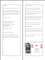
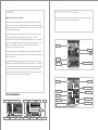
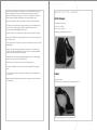
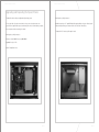
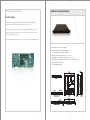
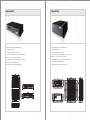
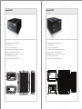
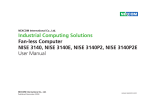
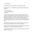
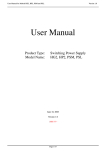
Amplicon Computer user manual
Amplicon Computer user manual
Safety Instructions
Operation of your PC
Before you unpack your PC system, ensure you carefully read through this manual and
Before operating your computer please: -
follow any related safety or operational instructions.
Read the equipment ratings plate and ensure that the mains circuit is suitably rated to
Only suitably qualified and experienced personnel should work inside the computer.
power the equipment, to avoid risk of overloading. Do not use mains adaptors, or
extenders.
Before commencing work within the PC ensure that the mains is disconnected from the
PC and any attached peripherals.
Ensure that any cables connecting to the equipment are made safe and do not present a
tripping hazard.
To avoid risk of electric shock ensure that equipment is plugged into a suitably grounded
mains outlet. Only use the power cord supplied with your PC. Do not continue to use the
cable if it is cut or damaged
---Ensure the chassis is kept away from heat sources, such as radiators and heating vents.
Chassis ventilation slots must be kept clear and not blocked. Failure to do so is likely to
cause the unit to overheat and become unstable.
Avoid connecting the PC to an electrical supply which may have unacceptable
interruptions, surges, spikes or noise. We recommend the use of an uninterruptible power
supply (UPS), surge protector or mains conditioner to address the problem.
Page 02
Page 03
Amplicon Computer user manual
Amplicon Computer user manual
Rack Mounted Equipment
Please read this section carefully before assembling your industrial computer as part of an
Consideration must be given to overall mechanical stability. Please ensure adherence to the
enclosure or multi-rack assembly. It is highly recommended that any work of this nature
user instructions of your chosen enclosure or rack.
only be undertaken by competent, trained personnel. These guidelines must be read in
Typical weights of our Ventrix and Impact systems are: -
conjunction with the user guide of the enclosure and any other equipment to be fitted.
Ventrix / Impact 1xxx (1U)
Ventrix / Impact 2xxx (2U)
Ventrix / Impact 3xxx (3U)
Ventrix / Impact 4xxx (4U)
Ventrix / Impact 6xxx (6U)
· The maximum ambient operating temperature should not typically exceed 40°C. The
operating ambient temperature of the rack environment may be greater than room
temperature. The direct ambient environment must not exceed the maximum rating.
>8kg
>20kg
>20kg
>20kg
>30kg
The weight of a system will increase when it is expanded. The weight of additional drives
and plug-in cards must be considered.
· Allow free airflow around the chassis for safe operation. Place any fans or blowers
close to the heat generating devices. If using a fan, ensure that outside air is not
brought inside the enclosure unless a fabric or other reliable filter is used. This
filtration prevents conductive particles or other harmful contaminants from entering
the enclosure.
· Ensure the rating of the mains power outlet is not overloaded. The total power taken
by all the electrical devices must not exceed the maximum outlet rating. The total
maximum rating can be ascertained by the cumulative maximum ratings of all the
Warning
electrical devices running from the outlet. If the rating of any devices is in doubt,
When heavy equipment is extended on it’s slide rails there
please contact the respective manufacturer.
is a danger that the rack could topple over. We recommend
that the rack is secured to the floor or a suitable stabilising
· Care must be taken to ensure that all devices requiring a protective earth have a
plinth is used.
reliable earth connection, especially when the power is distributed by means of a
power- strip. It is recommended that after assembly and prior to the application of `
power, an earth-bonding test be carried out. Earth requirements may vary depending
upon your location, refer to any relevant local electric codes that provide data such as
the size and types of conductors, colour codes and connections necessary for safe
grounding of electrical components.
· Account for the unit's depth when choosing the depth of the enclosure.
· Consider accessibility, locations of accessories such as AC power outlets for
installation and maintenance convenience.
Page 04
Page 05
Amplicon Computer user manual
Amplicon Computer user manual
Electrostatic Discharge Damage
When working on the inside of a PC system, you must be aware that many of the
components are electrostatic discharge sensitive (ESD). These components can easily be
damaged if suitable precautions are not taken. ESD damage is not always immediately
apparent and may result in a failure many weeks later. When working on equipment we
recommend the use of an ESD mat and wrist strap.
Caution
Components inside of the case can be damaged by
electrostatic discharge (ESD). You must take suitable
precautions to prevent likely ESD damage.
This page has been intentionally kept blank
Page 06
Page 07
Amplicon Computer user manual
Amplicon Computer user manual
Introduction
Unpacking the system
Thank you for purchasing your industrial computer from Amplicon Liveline Limited.
Your system has been supplied in a custom designed heavy-duty cardboard box. It is
recommended that you retain all packaging material for future shipping purposes.
Your system has been assembled from quality components selected by our engineering
team. For increased reliability, all our systems undergo an over night diagnostic test and a
We take great care when shipping our systems, but recommend that you take a moment
copy of the diagnostic report will be included with your system. If you have specified an
to inspect your new system. If you have concerns that the unit has sustained transit
operating system, this will be installed together with any additional plug-in cards, or
damage. Contact our Support Department immediately.
software.
If your system features a single board computer (SBC), it will come with internal transit
When you unpack your system you will find:
packing foam. Systems fitted with internal packing foam have an additional caution label
across the power inlet. The packing foam safeguards against internal damage during
· This user guide
transit.
· A manual for the industrial single board computer, or motherboard
· Any specified plug-in card driver disks and manuals
Before you start using your new system, any internal packing foam must be removed.
· Any specified device software such as Nero, or Easy CD Creator
Anti-static precautions must be observed whilst removing the transit packing foam.
· Additional screws and fixings pack
· Any specified keyboard and mouse "Y" splitter
Removing transit packing foam
· Power cord
· Any specified keyboard, mouse or trackball
Locate and remove the screws securing the chassis top cover. Slide the top cover back and
· Keys
then lift it clear of the chassis. Carefully remove the pink packing foam, taking care not to
disturb the internals of your system, ensuring cables are not snagged whilst removing the
Contents may vary, depending on specified configuration.
foam.
The intention of this user guide is to get you acquainted with your new system and
Retain the packing foam with the other packing materials. The chassis top cover can now
provide general end-user information for the whole system. If you require more specific
be replaced and secured with the original screws.
technical information, please refer to the component manuals that are included with your
system.
Caution
Powering the system
without removing the
internal transit packing
foam will result in damage
Page 08
Page 09
Amplicon Computer user manual
Amplicon Computer user manual
Installation
Fitting ISA, PCI and PCI express
l
The following instructions describe the physical installation of ISA, PCI or PCI express plug-
Making connections to your computer
in cards. Please refer to the internal view photographs below.
Our range of industrial computers utilise either single board computers or conventional
ATX form factor motherboards. The exact positioning of each connector may vary slightly
from your specific machine. For detailed information, please refer to the processor board
manual supplied with your system.
Ensure that the mains power outlet is switched off and connect the mains power cord.
Connect the external devices whilst referring to the connections shown in the
photographs below. Some single board computer based systems use a "Y" splitter cable
to breakout the keyboard and mouse PS/2 connections from the single connector on the
system. Connect this cable to the rear PS/2 connector. The mouse and keyboard
Drive bay
connections are clearly marked on the cable.
CPU cooler
USB devices are designed to be hot-plugged, and may be connected when the system is
CPU
running. Once all the devices are connected, the mains power outlet can be switched on
and the unit turned on.
Card clamp
We supply both AT and ATX powered systems. AT systems have latching power switches
Power supply
and need to be manually switched off. The ON position is denoted by a "I", and OFF by a
Single board computer
"O". ATX systems have a momentary push button and can be automatically shut down by
most modern operating systems. To turn the unit off manually, depress and hold the
power switch for four seconds. If your computer has a rear PSU power switch, this must
also be switched to ON before the system can be powered.
Drive bay
Drive bay
Environmental monitor
CPU / cooler
ATX motherboard
Rear Connections
Power switch
Card clamp
PS/2 Mouse & PS/2 Keyboard
Power switch
Serial COM ports
VGA output
LAN
Power supply
ISA Expansion slots
32 Bit PCI expansion
PCI express x16 expansion slots
IEC Mains inlet
Onboard VGA
USB ports
Audio
IEC Mains inlet
Rear DIN Keyboard
Parallel port
USB ports
Page 10
Page 11
Amplicon Computer user manual
Amplicon Computer user manual
· Disconnect the mains power from your system. It is recommended that you leave the
power cord attached, but isolate the live mains feed from the power outlet. This
method will retain a protective earth to the chassis. Use an anti-static wrist strap to
avoid electrostatic discharge (ESD) damage to the system and plug-in card.
Impact-E 40 / 41 / 50 - Accesories
AC/DC Adapter
· When selecting a plug-in card, ensure that there is sufficient mechanical clearance.
Model Number: FSP120-AAB
· The system resource requirements for plug-in cards vary. It is recommended that you
check the resources required by your card(s) are available. Please refer to the
processor board manual supplied with your system.
AC input: 100 ~ 240VAC
DC output: 19V 6.32A (max)
Packaged gross weight: Approximately 6.8kg
· Remove the chassis cover retaining screws to gain access to the inside of the system.
· If your system is fitted with a card-retaining clamp, remove the screws securing it and
lift it from the chassis.
· Locate the position where you wish to insert your new card and remove the screw and
blanking plate.
· Insert you new card, ensuring you apply firm even pressure to the top edge of the
card. Once you have ensured that the connector is fully in the respective PCI/ISA/PCI
express socket, insert the bracket securing screw.
· If applicable, refit the card-retaining clamp and adjust the arm of the clamp to apply
firm pressure to the top of the newly inserted card.
· Refit the chassis cover and secure in place with the retaining screws.
· For software installation, please refer to the instructions supplied with your plug-in
card.
· You must check that there is sufficient power available to meet the requirements of
your new card.
Cables
· Additional cards could decrease airflow within the chassis and result in raised internal
case temperature.
Serial breakout cable
PS/2 splitted - must be used when attaching a keyboard and mouse
Page 12
Page 13
Amplicon Computer user manual
Amplicon Computer user manual
Upgrading and Expanding the Impact-E Series
The Impact-E series are sold pre-configured as fully working systems.
Removing the top will give access to: -
To access the inside of the unit remove either the six top cover or base plate screws. Your
Hard drive mounting:- A 2.5” parallel IDE hard drive may be added to the system. Ensure that the
system will come supplied with a processor and memory. We do not recommend that you replace
heat transfer plate makes good contact with the side of the chassis when fitting.
these components without contacting us for advice.
The Impact-E 40 / 50 can accept PCI expansion cards
Removing the top will give access to: Memory: 2 x 184-pin DIMM slots, accept DDR SDRAM
Upgradeable to: Up to 2 GB
Internal CompactFlash socket
Page 14
Page 15
Amplicon Computer user manual
Amplicon Computer user manual
Regulatory Compliance
Specifications
CE Marking
Electrical Ratings
We have run our own fully equipped EMC Pre-compliance facility for over 10 years. This facility is
Always check the ratings plate of your system for the correct specifications.
used to ensure the ongoing conformance of our products to the EMC Directive (2004/108/EC).
Our systems incorporate Zippy industrial power supplies (PSUs). The following models are
As standard our systems meet or exceed the requirements of IT Equipment as defined in the
standard for many of our systems.
Harmonised Product Standards for Information Technology Equipment. As the majority of our
customers work within industry, most of our products meet Class A Emissions.
Standard 460W (HP2-6460P)
We can also taylor testing packages to ensure equipment meets the requirements of many other
Voltage:
90 ~264 VAC Full Range
standards such as Railways or London Underground.
Frequency:
47 ~ 63 Hz
Input Current:
If you require a CE Declaration a member of our support team will be happy to provide you with
a copy.
7.0A for 115 VAC
3.5A for 230 VAC
Inrush Current
65A Max for 115 VAC
125A Max for 230 VAC
If you require additional testing or have any questions concerning product conformance, please
contact our Engineering Manager.
Standard 600W (PSM-6600P)
Voltage:
90 ~264 VAC Full Range
Frequency:
47 ~ 63 Hz
Input Current:
10.0A for 115 VAC
5.0A for 230 VAC
Inrush Current
65A Max for 115 VAC
125A Max for 230 VAC
Standard 400W+400W Redundant (MRW-6400P)
Voltage:
90 ~264 VAC Full Range
Frequency:
47 ~ 63 Hz
Input Current:
8.0A for 115 VAC
6.4A for 230 VAC
Inrush Current
60A Max for 115 VAC
80A Max for 230 VAC
Page 16
Page 17
Amplicon Computer user manual
Amplicon Computer user manual
Mechanical Specifications
Ventrix 1xxx Series Chassis
Ventrix Range
The Ventrix series utilise single board computer (SBC) and complementary backplane
technology. All our Ventrix products have a typical life cycle of 5 years.
This series provides a wide performance range to meet different application needs. In
addition, each model is offered with a choice of PCI/ISA/PCI express expansion options.
Systems can be specially customised.
All of our Ventrix products use Intel processors supported by the Intel Embedded Roadmap
Design: EIA RS-310C 19" Rackmount Standard
Construction: Heavy duty cold rolled electroplated steel
Colour: Black (custom colours available for large orders)
Dimensions: 483 (W) x 44 (H) x 450 (D) mm (19" x 1.7" x 17.7")
Packaging size: 615 (W) x 179 (H) x 600 (D) mm (24.2" x 7.0" x 23.6")
Total drive capacity: 1 x slim CDROM, 2 x 3.5" HDD, 1 x slim 3.5" floppy disk drive
Cooling: 3 x 40mm fan, 7 CFM each
Gross weight: approximately 8kg
18.00
430.00
AIR
FLOW
AIR
FLOW
I
O
Slim FDD
92.00
120.00
92.00
450.00
(Left Side)
Full Card * 1
92.00
Rear view
Slim CD-ROM
AIR
FLOW
*&&
Front view - door removed
Top View
Right View
Left View
482.60
2x3.5" HDD
466.60
219'4
Page 18
43.40
Front view - door removed
Front view - door closed
31.80
*&&
*&&
Page 19
Amplicon Computer user manual
Amplicon Computer user manual
Ventrix 2xxx Series Chassis
Ventrix 4xxx Series Chassis
Design: EIA RS-310C 19" Rackmount Standard
Design: EIA RS-310C 19" Rackmount Standard
Construction: Heavy duty cold rolled electroplated steel
Construction: Heavy duty cold rolled electroplated steel
Colour: Black (custom colours available for large orders)
Colour: Black (custom colours available for large orders)
Dimensions: 483 (W) x 88 (H) x 450 (D) mm (19" x 3.5" x 17.7")
Dimensions: 480 (W) x 177 (H) x 510 (D) mm (19" x 7" x 20.1")
Packaging size: 630 (W) x 248 (H) x 574 (D) mm (24.8" x 9.8" x 22.6")
Packaging size: 600 (W) x 345 (H) x 690 (D) mm (23.6" x 13.6" x 27.2")
Total drive capacity: 1 x 5.25" + 1 x 3.5" FDD, or 1 x Slim CDROM, 1 x 3.5" HDD, 1 x 3.5" FDD
Total drive capacity: 4 x 5.25" + 1 x 3.5" FDD
Cooling: 3 x 80mm fan, 42.5 CFM each
Cooling: 1 x 120mm fan, 108 CFM
Air filter: removable (washable)
Air filter: removable (washable)
Gross weight: approximately 20kg
Gross weight: approximately 20kg
Page 20
Page 21
Amplicon Computer user manual
Amplicon Computer user manual
Ventrix 6xxx Series Chassis
Ventrix-W 4xxx Series Chassis
Design: EIA RS-310C 19" Rackmount Standard
Design: EIA RS-310C 19" Rackmount Standard
Construction: Heavy duty cold rolled electroplated steel
Construction: Heavy duty cold rolled electroplated steel
Colour: Black (custom colours available for large orders)
Colour: Black (custom colours available for large orders)
Dimensions: 483 (W) x 267 (H) x 463 (D) mm (19" x 10.5" x 18.2")
Dimensions: 483 (W) x 177 (H) x 510 (D) mm (19" x 7" x 20.1")
Packaging size: 610 (W) x 418 (H) x 647 (D) mm (24.0" x 16.5" x 25.5")
Packaging size: 591 (W) x 340 (H) x 688 (D) mm (23.3" x 13.4" x 27.1")
Total drive capacity: 4 x 5.25" + 1 x 3.5" HDD + 1 x 3.5" floppy disk drive
Total drive capacity: 1 x 5.25" + 3 x 3.5" HDD Caddy (SATA, SAS & SCSI320 available)
Cooling: 4 x 90mm fan, 90 CFM each
Cooling: 3 x 92mm fan, 51 CFM each
Air filter: removable (washable)
Gross weight: approximately 20kg
Gross weight: approximately 28kg
101.60
177.00
482.60
Keyboard & Mousepad drawer
Front out-side view
Rear out-side view
427.00
AIR
OUT
177.00
92.10
92.10
FAN
AIR
FLOW
AIR
FLOW
AIR
FLOW
FAN
FAN
FAN
92.10
92.10
Hold Down Bar
120.00
3.5"HDD
5.25” CD-ROM
I
O
POWER
R ESET
Alarm
Left-side View
Page 22
Top View
Right-side View
Page 23
Amplicon Computer user manual
Amplicon Computer user manual
Ventrix 5xx Series Chassis
Impact / Impact-R Range
The Impact-R series incorporates DFI industrial motherboards to achieve hardware life cycles
of up to five years. These models provide a wide performance range to meet different
application needs.
The Impact range is designed and built by Amplicon under ISO9001:2000 quality
management procedures. They offer premium value and provide a bridge between business
and top-end industrial systems. Every Impact is constructed in heavy-duty steel chassis, built
to industrial standards.
All of our Impact-R and Impact products use Intel processors supported by the Intel
Embedded Roadmap.
Design: Desktop or wall mount
Construction: Heavy duty cold rolled electroplated steel
Colour: Black (custom colours available for large orders)
Dimensions: 177 (W) x 350 (H) x 411 (D) mm (13.8" x 7.0" x 16.2")
Packaging size: 490 (W) x 324 (H) x 558 (D) mm (19.3" x 12.8" x 22.0")
Total drive capacity: 2 x 5.25", 1 x 3.5" HDD, 1 x 3.5" floppy disk drive
Cooling: 1 x 120mm fan, 90 CFM
Air filter: removable (washable)
411.20
Gross weight: approximately 17kg
Rear View
Top View
350.00
177.00
Side View
Front View
Page 24
Page 25
Amplicon Computer user manual
Amplicon Computer user manual
Impact / Impact-R 1xxx Series Chassis
Impact / Impact-R 2xxx Series Chassis
Design: EIA RS-310C 19" Rackmount Standard
Design: EIA RS-310C 19" Rackmount Standard
Construction: Heavy duty cold rolled electroplated steel
Construction: Heavy duty cold rolled electroplated steel
Colour: Black (custom colours available for large orders)
Colour: Black (custom colours available for large orders)
Dimensions: 483 (W) x 44 (H) x 543 (D) mm (19” x 1.7” x 21.4”)
Dimensions: 483 (W) x 88 (H) x 450 (D) mm (19.0” x 3.5” x 17.7”)
Packaging size: 560 (W) x 185 (H) x 671 (D) mm (22.1" x 7.3" x 26.4")
Packaging size: 615 (W) x 224 (H) x 600 (D) mm (24.2" x 8.8" x 23.6")
Total drive capacity: 1 x Slim CD-ROM, 1 x Slim FDD external, 1 x 3.5” internal
Total drive capacity: 1 x Slim 5.25” external, 1 x 3.5” external, 4 x 3.5” internal
or 1 x 5.25” external, 1 x 3.5” external, 3 x 3.5” internal
Cooling : 6 x 40mm dual ball bearing fans (15.3CFM each)
Cooling : 3 x 80mm ball bearing fans (42.5 CFM each)
Gross weight: approximately 12kg
Air filter: removable (washable)
Gross weight: approximately 17kg
430.00
AIR
AIR
FLOW
FLOW
92.10
21.70
Rear view
ATX M/B
.#0
540.00
92.10
92.10
4'5'6
*&&
.#0
219'4
92.10
Front in-side view
POWER
12"x13"
AIR
AIR
AIR
AIR
FLOW
FLOW
FLOW
FLOW
CON2
G
120.00
CON1
465.60
31.80
43.60
482.60
FAN1
FAN2
FAN4
FAN5
FAN3
5.25"Slim CD-Rom x 1
FAN6
- +
- +
+
3.5"Slim FDD x 1
3.5"HDD x 1
CN1
USB
*&&
219'4
.#0
.#0
Front out-side view
Left View
Top View
Page 26
Page 27
Amplicon Computer user manual
Amplicon Computer user manual
Impact / Impact-R 3xxx Series Chassis
Impact / Impact-R 4xxx Series Chassis
Design: EIA RS-310C 19" Rackmount Standard
Design: EIA RS-310C 19" Rackmount Standard
Construction: 1.2mm SECC Zinc-Coated Steel
Construction: 1.2mm SECC Zinc-Coated Steel
Colour: Black (custom colours available for large orders)
Colour: Black (custom colours available for large orders)
Dimensions: 483 (W) x 133 (H) x 526 (D) mm (19” x 5.2” x 20.7”)
Dimensions: 485 (W) x 176.8 (H) x 480 (D) mm (19.1” x 7.0” x 18.9”)
Packaging size: 588 (W) x 285 (H) x 703 (D) mm (23.1" x 11.2" x 27.7")
Packaging size: 541 (W) x 280 (H) x 660 (D) mm (21.3" x 11.0" x 26.0")
Total drive capacity: 2 x 5.25”, 1 x 3.5” external, 4 x 3.5” internal
Total drive capacity: 4 x 5.25” external, 1 x 3.5” external, 2 x 3.5” internal
Cooling : 1 x 80mm, 2 x 92mm ball bearing fan
Cooling: 1 x 120mm ball bearing fan
Air filter: removable (washable)
Air filter: removable (washable)
Gross weight: approximately 18kg
Gross weight: approximately 20kg
528.00
176.80
480.00
427.00
465.00
485.00
Page 28
Page 29
Amplicon Computer user manual
Amplicon Computer user manual
Impact-R 15x Series Chassis
Impact-R 2xx Series Chassis
Design: Compact desktop / wallmount (brackets supplied)
Design: Compact desktop / wallmount (brackets supplied)
Construction: Heavy duty cold rolled electroplated steel
Construction: Heavy duty cold rolled electroplated steel
Colour: Black / Silver (custom colours available for large orders)
Colour: Black / Silver (custom colours available for large orders)
Dimensions: 280 (W) x 77 (H) x 268 (D) mm (11.0" x 3.0" x 10.6")
Dimensions: 350 (W) x 90 (H) x 268 (D) mm (13.8" x 3.5" x 10.6")
Packaging size: 373 (W) x 363 (H) x 175 (D) mm (14.7" x 14.3" x 6.9")
Packaging size: 470 (W) x 390 (H) x 235 (D) mm (18.5" x 15.4" x 9.3")
Total drive capacity: 1 x Slim 5.25” external, 2 x 2.5” internal
Total drive capacity: 1 x Slim 5.25” external, 2 x 2.5” internal
Cooling : 1 x 60mm ball bearing fan (23.5 CFM each)
or 1 x 3.5” internal, 1 x 2.5” internal
Gross weight: approximately 4kg
Cooling : 2 x 60mm ball bearing fan (23.5 CFM each)
Gross weight: approximately 6kg
267.3 mm
269.0 mm
73.8 mm
350.0mm
90.0 mm
76.60 mm
279.4 mm
Page 30
Page 31
Amplicon Computer user manual
Amplicon Computer user manual
Impact-E 20
Impact-E 40
Design: Rugged compact embedded design
Design: Rugged compact embedded design
Cooling: Fanless design
Cooling: Fanless design
Construction: Heavy duty aluminium
Construction: Heavy duty aluminium
Colour: Black (custom colours available for large orders)
Colour: Black (custom colours available for large orders)
Dimensions: 260 (W) x 55 (H) x176 (D) mm
Dimensions: 195 (W) x 80 (H) x 268 (D) mm
Packaging dimensions: 290 (W) x 180 (H) x 380 (D) mm
Packaging dimensions: 310 (W) x 240 (H) x 360 (D) mm
Gross weight: Approximately 2.5kg
Gross weight: Approximately 4.4kg
Packaged gross weight: Approximately 3.4kg
Packaged gross weight: Approximately 6.5kg
Page 32
Page 33
Amplicon Computer user manual
Amplicon Computer user manual
Impact-E 41
Impact-E 50
Design: Rugged compact embedded design
Design: Rugged compact embedded design
Cooling: Fanless design
Cooling: Fanless design
Construction: Heavy duty aluminium
Construction: Heavy duty aluminium
Colour: Black (custom colours available for large orders)
Colour: Black (custom colours available for large orders)
Dimensions: 195 (W) x 80 (H) x 268 (D) mm
Dimensions: 195 (W) x 107 (H) x 268 (D) mm
Packaging dimensions: 310 (W) x 240 (H) x 360 (D) mm
Packaging dimensions: 310 (W) x 240 (H) x 360 (D) mm
Gross weight: Approximately 4.4kg
Gross weight: Approximately 4.7kg
Packaged gross weight: Approximately 6.5kg
Packaged gross weight: Approximately 6.8kg
195.00
107.00
101.00
PWR
LNK1
LNK2
HDD
ACT1
ACT2
268.00
264.00
224.00
184.00
268.00
219.00
207.00
195.00
195.00
207.00
219.00
207.00
219.00
195.00
2
LVDS
ON
OFF
DC IN
12V 30V
8
6
5
3
2
1
COM1 COM4
184.00
224.00
264.00
268.00
Page 34
Page 35
Amplicon Computer user manual
Amplicon Computer user manual
Maintenance
Product Repair / Returning a Unit to Amplicon
Modern computer systems can generate a large amount of heat within the chassis.
If you are encountering technical difficulties with your system, please contact our Technical
The internal temperature of the chassis is kept within operating limits by forced air
Support Team. Free technical support is provided throughout the warranty period of the
cooling. Most systems have a number of fans, which must be maintained to allow free
product. You can reach our Technical Support Team during the hours of 08:30 to 17:30
airflow. Some of our chassis have air intake fan filters, which prevent contaminants
GMT via:
from entering the inside of your system.
· Telephone: +44 (0) 1273 608331
Preventative Maintenance
· Fax: +44 (0) 1273 570 215
· Web: www.amplicon.co.uk
· Email: [email protected]
Caution
An online support request form is available form our website.
Blocked fan filters may result in your system
overheating and being damaged
When calling please ensure that you have your company details and purchase order details
to hand.
· Clean the fan filters periodically to ensure that the air circulating in the unit is clean.
No goods should be sent back to Amplicon Liveline Limited without obtaining a Returns
Wash the filter with warm soapy water and let it dry naturally. Do not scrub the filter
Materials Authorisation (RMA) number prior to shipment.
and do not install it into the unit until it is completely dry.
· Base your maintenance schedule on the operating environment of the system. If the
area is dusty, you should schedule maintenance more often than if it is a dry, clean
area. Check the filter often to determine if it needs to be changed ahead of schedule.
· Remove dust and dirt from system components. If dust builds up on heat sinks and
circuitry, an obstruction of heat dissipation could cause the unit to malfunction. If dust
reaches the electronic boards, a short circuit could occur.
· Check the connections to input/output modules, especially in environments where
vibration could loosen the connections, and see that all plugs, sockets, terminal
strips and module connections are secure.
· Ensure that air intake and exhaust points are free from obstructions.
· Stock spare parts to minimise down time resulting from part failure. Whether it is a
custom or off-the-shelf spares package, we can provide a solution.
Page 36
Page 37
Amplicon Computer user manual
Amplicon Computer user manual
Terms and Conditions
End of Life Processing
Our Terms and Conditions are available to view or download at the following link : -
The requirements of WEEE (Waste Electrical and Electronic Equipment) apply to this product.
http://www.amplicon.co.uk/terms.pdf
You, the customer, are the final user as defined by this Regulation. If you purchase replacement
equipment from Amplicon, we shall bear the cost of removal and proper disposal of this product.
Onsite maintenance
Amplicon's WEEE Producer Registration Number is available on our website:
http://www.amplicon.co.uk/weee.cfm
This chapter is only applicable to systems supplied with one of our onsite maintenance
contracts.
Required Tools For Dismantling
Before requesting an onsite visit, you must discuss your problem with a member of our
No. 1 Phillips screwdriver
Technical Support Team. If we are unable to resolve your problem over the phone, we will
Nut spinner 5mm
arrange an onsite visit in line with our Maintenance Service Terms and Conditions of
Light gauge wire cutters
Service.
Dismantling Procedure
When wishing to arrange a visit, please ensure you have the correct and full address
Our systems can easily be dismantled using the tools listed. All mechanical fixings are made by
details to hand.
M2, M3 and M4 screws or threaded posts. Wire cutters are required to cut the plastic cable ties
and any other plastic cable management.
Please ensure you read our Terms and Conditions which cover our Onsite Maintenance.
Locate the top cover and remove the securing screws. Once the cover is removed you will be able
to see within the unit.
The system can easily be broken down into the following components: Metal chassis parts (electron galvanised steel)
Printed circuit board assemblies (fibreglass PCB material)
Chassis fans (Plastic resin and electronic components)
Some systems are fitted with batteries such as lithium used for system CMOS backup. Make sure
these are removed in the first instance and disposed of in an appropriate manner. Batteries will
be either retained by a quick release clip, or soldered in place. If they are soldered, they should be
removed by cutting the component legs.
Page 38
Page 39
The information contained has been reviewed and is believed to be accurate and
reliable, however Amplicon Liveline Limited accepts no responsibility for any problems caused by errors or omissions.
Specifications and instructions are subject to change without notice.
Computer User Guide Part No 85040046 Issue D. Amplicon Liveline Limited
Prepared by R Cobden, Engineering Manager