1
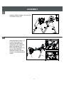
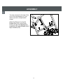
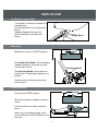
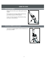
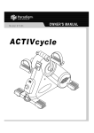
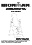
OWNER’S MANUAL
AB TRAINING INVERSION SYSTEM
LXT 850
Model # 5906
The specifications of this product may vary from this photo and are subject to change without notice.
IRONMAN, IRONMAN TRIATHLON AND M-DOT are registered trademarks of World Triathlon Corporation.
This product is licensed by the IRONMAN TRIATHLON.
TABLE OF CONTENTS
Page #
Warning label placement
3
Service
4
Safety precautions
5
Included hardware & tools
6
Overview drawing
7
Part list
8
Assembly
10
How to use
15
Maintenance instructions
17
Warm-up
18
Warranty
19
Part request fax foam
20
2
WARNING LABEL PLACEMENT
3
SERVICE
To request for product service and order replacement parts, please call our
customer service department at
1-866-924-1688
Monday through Friday, 8:00 am-5:00 pm Pacific Standard Time,
or email at: [email protected]
Please have the following information ready when requesting for service:
Your name
Model number
Date of Purchase
Phone number
Serial number
Owner’s manual
Part number
*If the product has major defects which prevent it from functioning
properly, please return it to the store of purchase within the period
allowed by the store.
Paradigm Health & Wellness, Inc.
1189 Jellick Ave.
City of Industry, CA 91748
4
SAFETY PRECAUTIONS
This inversion table was designed and built for optimum safety. However, certain precautions
apply whenever you operate the exercise equipment. Be sure to read the entire manual before
assembling and operating this equipment. Also, please note the following safety instructions:
1. Consult your physician or other health care professionals before using the inversion table.
2. Always wear proper exercise apparel when using the equipment.
3. If any time you feel faint, light-headed or dizziness while operating the equipment, stop
exercise immediately. You should also stop exercising if you are experiencing pain or
pressure.
4. Keep children and pets away from the equipment while in use.
5. Only one person should use the equipment at a time.
6. Make sure your equipment is correctly assembled before you use it. Be sure all screws,
nuts, and bolts are tightened prior to use.
7. Do not operate this or any exercise equipment if it is damaged.
8. Watch your body: come up slowly, dizziness after a session means you came up too fast.
Wait a while after eating before using the inversion table. If you get nauseous, come up as
soon as you feel queasy.
9. Always use this equipment on a clear and level surface. Do not use outdoors or near water.
10. Keep hands and feet away from any moving parts. Do not insert any object into any openings.
11. Keep loose clothes, jewelry away from moving parts.
12. WARNING: ALWAYS HOLD ON TO THE SAFETY HANDLES AND GO BACK SLOWLY
WHEN INVERTING. FAILURE TO COMPLY COULD RESULT IN SERIOUS BODILY INJURY.
13. Children under the age of 12 should not use the following fitness equipment.
WARNING: Consult with your personal physician to see if inversion equipment is appropriate for
you. This is especially important for people with pre-existing health problems. Do not use this
equipment without your physician's approval.
Do not use this equipment if you have any of the following conditions or ailments:
.Extreme obesity
.Glaucoma, retinal detachment or conjunctivitis
.Pregnancy
.Spinal injury, Cerebral Sclerosis, or acutely swollen joints
.Middle ear infection
.High blood pressure, Hypertension, Recent stroke or Transient Ischemic attack
.Heart or circulatory disorders for which you are being treated
.Hiatus hernia or Ventral hernia
.Bone weaknesses including Osteoporosis, Unhealed fractures, Modularly pins, or
Surgically implanted orthopedic supports.
.Use of anti-coagulants including Aspirin in high doses.
Maximum Weight Capacity is 300 lbs/ 136 kgs.
5
INCLUDED HARDWARE & TOOLS
(31) Knob
(52) Nylon Washer
Ø45xØ3/8"x19L Ø25xØ8.5xt2.5
1 PC
1 PC
(55) Allen Head Bolt (56) Allen Head Bolt
M10x55
M10x40
2 PCS
2 PCS
(58) Allen Head Bolt (62) Allen Head Bolt (63) Allen Head Bolt (64) Allen Head Bolt
M8x20
M10x45
M6x15
M8x40
2 PCS
2 PCS
2 PCS
5 PCS
(66) Hex Head Bolt
M6x40
1 PC
(67) Hex Head Bolt
M8x45
1 PC
(77) Lock Nut M10 (79) Lock Nut M8
1 PC
(black)
2 PCS
(83) Washer
Ø11xØ20xt2
4 PCS
(68) Phillips Bolt
M6x20
4 PCS
(73) Screw
ST4.8x20mm
1 PC
(80) Lock Nut M6
(82) Washer
1 PC
Ø11xØ20xt2 (black)
6 PCS
(84) Washer
(85) Washer
(86) Washer
Ø8.5xØ20xt1.5 Ø8.5xØ20xt1.5 (black) Ø6.5xØ16xt1.0
1 PC
7 PCS
4 PCS
(87) Curve Washer (89) Allen Head Bolt (90) Lock Nut M10
2 PCS
Ø6.5xØ16xt1.0
M8x60
2 PCS
1 PC
Phillips Screwdriver
1 PC
Allen wrench
1 PC
Allen wrench
1 PC
6
Wrench
2 PCS
OVERVIEW DRAWING
7
PART LIST
Part#
Description
001 Right Rear Frame
002
003
004
005
006
007
008
009
010
011
012
013
014
015
016
017
018
019
020
021
022
023
024
025
026
027
028
029
030
031
032
033
034
Quan. Part#
Description
Quan.
1 035 Front Foot Stabilizer
2
108x98xt34.5
Front Frame
1 036 Rear Foot Stabilizer
2
108x98xt34.5
Pivot Frame
1 037 In-Step Frame End Cap
2
Boom
1 038 Spring
Knob Ø32xØ9.3xt161x53
1
20x60xt1.5
Rear Rod
1 039 ABS Cover Ø105xØ22.5x10
1
In-Step Frame
1 040R Right Protective Cover 750x250
1
Pivot Arm
1 040L Left Protective Cover 750x250
1
Adjustable Locking Rod
1 041 Inner Cover Ø89xt18
1
Support
1 042 Gear Cover I 190x101xt16
1
Left Rear Frame
1 043 Gear Cover II 190x145xt32
1
Inversion Handle
1 044 Pivot Arm Cover I
1
Heel Holder Frame
1 045 Pivot
Arm Cover II
1
158.5x132.5xt20
Headrest
1 046 Bottle
Holder 159x93x102
1
158.5x132.5xt20
Foam Bed
1 047 Outer Cover Ø89xt18
1
Handlebar
2 048 Heel Holder
4
Round Plate
1 049 Spring Ø16x50xØ1.5
1
Bed Frame
1 050 Plastic Handle 124x80x32
1
Folding Arm
2 051 Height Scale
1
Long Shaft
1 052 Nylon Washer Ø25xØ8.5xt2.5
1
Short Shaft
1 053 Oval End Cap 25x50xt1.5
5
Gear Disk
1 054 Bearing 6203
2
Angle Adjustable Handle
1 055 Allen Head Bolt M10x55
2
Lumbar Pad
1 056 Allen Head Bolt M10x40
2
Rubber Pad 68x38xt28
1 057 Allen Head Bolt M10x15
1
Square End Cap □38x38xt2.0
1 058 Allen Head Bolt M8x20
2
Square End Cap □33.4x33.4xt2.0 2 059 Allen Head Bolt M8x15
1
Rod Cap Ø22xt1.5
4 060 Allen Head Bolt M8x22
2
Lower Bed Frame Bushing
2 061 Allen Head Bolt M6x10
1
Upper
Boom Bushing
1 062 Allen Head Bolt M10x45
2
50x38x205
□50x50xt2.0
Plastic Bushing □38x38xt25
1 063 Allen Head Bolt M6x15
2
Knob Ø45xØ3/8"x19L
1 064 Allen Head Bolt M8x40
9
Round End Cap Ø25
2 065 Hex Head Bolt M6x48
1
Spring Ø8x40xØ1.2
1 066 Hex Head Bolt M6x40
1
Foam Grip Ø24xØ32x(935)
2 067 Hex Head Bolt M8x45
1
8
PART LIST
Part#
068
069
070
071
072
073
074
075
076
077
078
079
Description
Phillips Bolt M6x20
Phillips Bolt M6x35
Bolt M6x12
Screw M3.5x15mm
Screw M3.5x12mm
Screw ST4.8x20mm
Screw M4x20mm
Screw M4x10mm
Lock Nut M12
Lock Nut M10 (black)
Lock Nut M8 (black)
Lock Nut M8
Quan. Part#
4 080
4 081
4 082
3 083
3 084
1 085
4 086
2 087
2 088
2 089
4 090
3 091
9
Description
Lock Nut M6
Washer Ø13.5xØ24xt2.5
Washer Ø11xØ20xt2 (black)
Washer Ø11xØ20xt2
Washer Ø8.5xØ20xt1.5
Washer Ø8.5xØ20xt1.5 (black)
Washer Ø6.5xØ16xt1.0
Curve Washer Ø6.5xØ16xt1.0
Spring Washer Ø6.1xØ7.8xt1.6
Allen Head Bolt M8x60
Lock Nut M10
Washer Ø17.5xØ30xt3.0
Quan.
6
2
6
5
6
15
10
2
4
1
2
2
ASSEMBLY
1
Install the Rubber Pad (24) onto the
Front Frame (2).
Stand up the base of the machine
by separating the frames. Pull the
Front, Left and Right Rear Frames
(2, 10, 1) as far apart from each
others as possible. Then push
down on the middle of the two
Folding Arms (18) until they are
fully locked down.
Attach the Front Foot Stabilizers
(35) to the Front Frame (2) each
with one M6x20 Phillips Bolt (68)
and Ø6.5xØ16xt1.0 Washer (86).
Attach the Rear Foot Stabilizers (36)
to the Left and Right Rear Frames
(10, 1) each with one M6x20
Phillips Bolt (68) and Ø6.5xØ16xt1.0 Washer (86).
Attach both Left and Right Protective Covers (40L, 40R) onto the Front, Left and
Right Rear Frames (2, 10, 1) with the velcro straps on the side of the Left and Right
Protective Covers (40L, 40R) to secure the covers to the Front, Left and Right Rear
Frames (2, 10, 1). Pull down on the Left and Right Protective Covers (40L, 40R)
until the bottom of the covers are slightly lower than the Folding Arms (18). When
the covers are assembled correctly, the Folding Arms (18) should be fully covered by
the Left and Right Protective Covers (40L, 40R).
2
Attach the Handlebars (15) onto the
Left and Right Rear Frames (10, 1)
with two M10x45 Allen Head Bolts
(62), M6x15 Allen Head Bolts (63),
Ø6.5xØ16xt1.0 Curve Washers
(87), M10 Lock Nuts (90), and four
Ø11xØ20xt2 Washers (black) (83).
10
ASSEMBLY
3
Install the Bottle Holder (46) onto the
Left Rear Frame (10).
4
A
Attach the Bed Frame (17)
to the Pivot Frame (3)
with two M10x40 Allen
Head Bolts (56), M10x55
Allen Head Bolts (55),
M10 Lock Nut (black) (77),
and six Ø11xØ20xt2
Washers (black) (82) as
shown in small drawings A
and B.
B
11
ASSEMBLY
5
Attach the Foam Bed (14) onto the
Bed Frame (17) with four M8x40
Allen Head Bolts (64) and
Ø8.5xØ20xt1.5 Washers (black)
(85).
6
Pull out the Spring Knob (38) and
slide the Boom (4) into the square
bracket on the bottom of the Bed
Frame (17) as shown. Slide the
Boom (4) upward until the desired
height on the height scale is just
below the bracket on the Bed
Frame (17). Lock the Boom (4)
in place by releasing the Spring
Knob (38) and sliding the Boom
(4) up or down slightly until the
Spring Knob (38) "pops" down
into the locked position. For
added safety, secured the Knob
(31) into the back side of the
bracket on the Bed Frame (17) as
shown.
12
ASSEMBLY
7
Remove four M4x20 Screws (74) from
both Rear Rod (5) and Heel Holder
Frame (12).
Attach one Heel Holder (48) to one end
of the Rear Rod (5). Slide the Rear
Rod (5) through the large round hole
on the side of Boom (4) as shown, and
attach the other Heel Holder (48) to the
other end of the Rear Rod (5).
Secure both Heel Holders (48) on the
Rear Rod (5) with two M4x20 Screws
(74) that were removed.
Slide the In-Step Frame (6) into the
bottom of the Boom (4) and align one
of the holes on the In-Step Frame (6)
with one hole on the bottom of the
Boom (4). Secure the In-Step Frame (6) in place using one M8x45 Hex Head Bolt
(67), Ø8.5xØ20xt1.5 Washer (84), and M8 Lock Nut (79).
Attach the Heel Holder Frame (12) to the Boom (4) by inserting the Heel Holder
Frame (12) into the square bracket on the boom. Slide the Heel Holder Frame (12)
completely into the square bracket and secure it with a M6x40 Hex Head Bolt (66)
and M6 Lock Nut (80). Finally, secure both Heel Holders (48) on the Heel Holder
Frame (12) with two M4x20 Screws (74) that were removed.
8
Attach the Headrest (13) onto the Bed
Frame (17) with one M8x40 Allen Head
Bolt (64), two M8x20 Allen Head Bolts
(58), and three Ø8.5xØ20xt1.5
Washers (black) (85).
Insert the Velcro strap from the Foam
Bed (14) to the underneath of Lumbar
Pad (23) and secure the Lumbar Pad
(23) onto the Foam Bed (14).
13
ASSEMBLY
9
You can proceed to this step if the
unit is for retail display or if you
wish to prevent unsupervised
usage.
Attach the Boom (4) onto the
Rubber Pad (24) on the Front
Frame (2) with one M8x60 Allen
Head Bolt (89) and Ø25xØ8.5xt2.5
Nylon Washer (52).
14
HOW TO USE
Set Boom to your height
Turn Knob in a counter-clockwise to
loosen Boom.
Pull Spring Knob as you adjust the
Boom.
Release Spring Knob and turn
Knob clockwise to de-rattle the
Boom.
Spring Knob
Boom
Knob
Mounting
Make Sure Lever is at STOP position.
To unlock Heel Holder: Press Release
Handle forward to unlock as you pull
Heel Holder Frame.
Release Handle
To lock Heel Holder: Press down on
Heel Holder Frame tightly against your
ankles.
Wearing shoes will help angles stay
more secure.
Pull Lever to FREE at vertical an
Get to inversion
Pull Lever to FREE position.
With both hands on handles, slowly lie
down.
If the bed does not rotate, raise the
Boom.
When you’re at desired angle, push
Lever forward to STOP position to lock
the bed.
15
HOW TO USE
Get to vertical angles
Raise both arms above your head, grad Inversion
Handle.
Push against the Inversion Handle with left arm,
push Lever forward to STOP position.
If you can’t reach Inversion Handle after raising
both arms, raise the Boom.
Pull Lever to FREE at vertical angles
Use left arm to push against Inversion Handle as you
pull Lever to FREE.
16
MAINTENANCE INSTRUCTIONS
You should check your inversion table for any kind of wear and tear before each use.
1.
2.
3.
Check the pivot arms, bed, heel holders for wear and tear.
Replace damaged and worn components immediately.
Keep all damaged equipment out of use until it is repaired.
17
WARM-UP
The WARM-UP is an important part of any workout. It should begin every session
to prepare your body for more strenuous exercise by heating up and stretching your
muscles, increasing your circulation and pulse rate, and delivering more oxygen to
your muscles.
HEAD ROLLS
Rotate your head to the
right for one count, feeling
the stretch up the left side
of your neck, then rotate
your head back for one
count, stretching your
chin to the ceiling and
letting your mouth open.
Rotate your head to the
left for one count, then
drop your head to your
chest for one count.
INNER THIGH STRETCH
Sit with the soles of your
feet together and your
knees pointing outward.
Pull your feet as close to
your groin as possible.
Gently push your knees
toward the floor. Hold for
15 counts.
SHOULDER LIFTS
Lift your right shoulder
toward your ear for one
count. Then lift your left
shoulder up for one count
as you lower your right
shoulder.
TOE TOUCHES
Slowly bend forward from
your waist, letting your
back and shoulders relax
as you stretch toward
your toes. Reach as far
as you can and hold for
15 counts.
SIDE STRETCHES
Open your arms to the
side and lift them until
they are over your head.
Reach your right arm as
far toward the ceiling as
you can for one count.
Repeat this action with
your left arm.
QUADRICEPS STRETCH
With one hand against a
wall for balance, reach
behind you and pull your
right foot up. Bring your
heel as close to your
buttocks as possible. Hold
for 15 counts and repeat
with left foot.
HAMSTRING
STRETCHES
Extend your right leg.
Rest the sole of your
left foot against your
right inner thigh.
Stretch toward your
toe as far as possible.
Hold for 15 counts.
Relax and then repeat
with left leg.
CALF/ACHILLES
STRETCH
Lean against a wall with
your left leg in front of the
right and your arms
forward. Keep your right
leg straight and the left
foot on the floor; then
bend the left leg and lean
forward by moving your
hips toward the wall.
Hold, then repeat on the
other side for 15 counts.
18
WARRANTY
Paradigm Inc. warrants to the original purchaser that this product is free from defects
in material and workmanship when used for the purpose intended, under the
conditions that it has been installed and operated in according to Paradigm’s Owner’s
Manual. Paradigm’s obligation under this warranty is limited to replacing free of
charge, any parts which may prove to be defective under normal home use. This
warranty does not include any damage caused by improper operation, misuse or
commercial application. From the date of purchase, the frame is warranted to be
free from defects for 1 (one) year. All parts and workmanship, including electronics
and its console cases, upholstery, foam, ball bearings, pulleys, cables, shocks, all
tension mechanisms, wheels, pedals and hardware are to be free from defects for 90
days. This warranty is offered only to the original owner and is not transferable.
Proof of purchase is required.
19
PART REQUEST FAX FORM
IRONMAN
PARTS REQUEST FAX FORM
Please fax this form to (1-626-810-2166)
OR YOU CAN EMAIL CUSTOMER SERVICE REQUESTS TO
[email protected]
NAME: ___________________________________________________________
ADDRESS: ________________________________________________________
CITY ___________ STATE _______________ ZIP _______________
TELEPHONE: (Day) _________________________________________________
(Night) ________________________________________________
(Email Address) ________________________________________
SERIAL#: _____________________________________________
MODEL#: _____________________________________________
PURCHASE DATE: _________________________________________________
PURCHASE FROM: _________________________________________________
PART #
DESCRIPTION
“YOUR ORDER WILL BE PROCESSED WITHIN 3 BUSINESS DAYS”
OFFICIAL USE ONLY
SHIP DATE: ___________________________________________
TRK #: _______________________________________________
BACK ORDER: ________________________________________
20
QTY